EP3704371B1 - Gdi pumpe mit direkteinspritzung und saugrohreinspritzung - Google Patents
Gdi pumpe mit direkteinspritzung und saugrohreinspritzung Download PDFInfo
- Publication number
- EP3704371B1 EP3704371B1 EP18807163.3A EP18807163A EP3704371B1 EP 3704371 B1 EP3704371 B1 EP 3704371B1 EP 18807163 A EP18807163 A EP 18807163A EP 3704371 B1 EP3704371 B1 EP 3704371B1
- Authority
- EP
- European Patent Office
- Prior art keywords
- fuel
- check valve
- outlet check
- control valve
- passage
- Prior art date
- Legal status (The legal status is an assumption and is not a legal conclusion. Google has not performed a legal analysis and makes no representation as to the accuracy of the status listed.)
- Active
Links
- 238000002347 injection Methods 0.000 title claims description 29
- 239000007924 injection Substances 0.000 title claims description 29
- 239000000446 fuel Substances 0.000 claims description 74
- 238000005086 pumping Methods 0.000 claims description 62
- 239000012530 fluid Substances 0.000 claims description 17
- 238000004891 communication Methods 0.000 claims description 5
- 238000011144 upstream manufacturing Methods 0.000 claims description 3
- 230000009977 dual effect Effects 0.000 description 4
- 230000001105 regulatory effect Effects 0.000 description 4
- 230000033228 biological regulation Effects 0.000 description 3
- 238000002485 combustion reaction Methods 0.000 description 3
- 230000001419 dependent effect Effects 0.000 description 2
- 239000003502 gasoline Substances 0.000 description 2
- 238000013507 mapping Methods 0.000 description 2
- 238000000034 method Methods 0.000 description 2
- 206010011906 Death Diseases 0.000 description 1
- 230000015572 biosynthetic process Effects 0.000 description 1
- 238000013461 design Methods 0.000 description 1
- 239000002828 fuel tank Substances 0.000 description 1
- 230000014759 maintenance of location Effects 0.000 description 1
- 238000005457 optimization Methods 0.000 description 1
- 238000012545 processing Methods 0.000 description 1
- 230000001360 synchronised effect Effects 0.000 description 1
Images


Classifications
-
- F—MECHANICAL ENGINEERING; LIGHTING; HEATING; WEAPONS; BLASTING
- F02—COMBUSTION ENGINES; HOT-GAS OR COMBUSTION-PRODUCT ENGINE PLANTS
- F02D—CONTROLLING COMBUSTION ENGINES
- F02D41/00—Electrical control of supply of combustible mixture or its constituents
- F02D41/30—Controlling fuel injection
- F02D41/3094—Controlling fuel injection the fuel injection being effected by at least two different injectors, e.g. one in the intake manifold and one in the cylinder
-
- F—MECHANICAL ENGINEERING; LIGHTING; HEATING; WEAPONS; BLASTING
- F02—COMBUSTION ENGINES; HOT-GAS OR COMBUSTION-PRODUCT ENGINE PLANTS
- F02D—CONTROLLING COMBUSTION ENGINES
- F02D41/00—Electrical control of supply of combustible mixture or its constituents
- F02D41/30—Controlling fuel injection
- F02D41/38—Controlling fuel injection of the high pressure type
- F02D41/3809—Common rail control systems
- F02D41/3836—Controlling the fuel pressure
- F02D41/3845—Controlling the fuel pressure by controlling the flow into the common rail, e.g. the amount of fuel pumped
-
- F—MECHANICAL ENGINEERING; LIGHTING; HEATING; WEAPONS; BLASTING
- F02—COMBUSTION ENGINES; HOT-GAS OR COMBUSTION-PRODUCT ENGINE PLANTS
- F02M—SUPPLYING COMBUSTION ENGINES IN GENERAL WITH COMBUSTIBLE MIXTURES OR CONSTITUENTS THEREOF
- F02M55/00—Fuel-injection apparatus characterised by their fuel conduits or their venting means; Arrangements of conduits between fuel tank and pump F02M37/00
- F02M55/02—Conduits between injection pumps and injectors, e.g. conduits between pump and common-rail or conduits between common-rail and injectors
- F02M55/025—Common rails
-
- F—MECHANICAL ENGINEERING; LIGHTING; HEATING; WEAPONS; BLASTING
- F02—COMBUSTION ENGINES; HOT-GAS OR COMBUSTION-PRODUCT ENGINE PLANTS
- F02M—SUPPLYING COMBUSTION ENGINES IN GENERAL WITH COMBUSTIBLE MIXTURES OR CONSTITUENTS THEREOF
- F02M59/00—Pumps specially adapted for fuel-injection and not provided for in groups F02M39/00 -F02M57/00, e.g. rotary cylinder-block type of pumps
- F02M59/02—Pumps specially adapted for fuel-injection and not provided for in groups F02M39/00 -F02M57/00, e.g. rotary cylinder-block type of pumps of reciprocating-piston or reciprocating-cylinder type
- F02M59/022—Pumps specially adapted for fuel-injection and not provided for in groups F02M39/00 -F02M57/00, e.g. rotary cylinder-block type of pumps of reciprocating-piston or reciprocating-cylinder type having an accumulator storing pressurised fuel during pumping stroke of the piston for subsequent delivery to the injector
-
- F—MECHANICAL ENGINEERING; LIGHTING; HEATING; WEAPONS; BLASTING
- F02—COMBUSTION ENGINES; HOT-GAS OR COMBUSTION-PRODUCT ENGINE PLANTS
- F02M—SUPPLYING COMBUSTION ENGINES IN GENERAL WITH COMBUSTIBLE MIXTURES OR CONSTITUENTS THEREOF
- F02M59/00—Pumps specially adapted for fuel-injection and not provided for in groups F02M39/00 -F02M57/00, e.g. rotary cylinder-block type of pumps
- F02M59/44—Details, components parts, or accessories not provided for in, or of interest apart from, the apparatus of groups F02M59/02 - F02M59/42; Pumps having transducers, e.g. to measure displacement of pump rack or piston
- F02M59/46—Valves
- F02M59/462—Delivery valves
-
- F—MECHANICAL ENGINEERING; LIGHTING; HEATING; WEAPONS; BLASTING
- F02—COMBUSTION ENGINES; HOT-GAS OR COMBUSTION-PRODUCT ENGINE PLANTS
- F02M—SUPPLYING COMBUSTION ENGINES IN GENERAL WITH COMBUSTIBLE MIXTURES OR CONSTITUENTS THEREOF
- F02M63/00—Other fuel-injection apparatus having pertinent characteristics not provided for in groups F02M39/00 - F02M57/00 or F02M67/00; Details, component parts, or accessories of fuel-injection apparatus, not provided for in, or of interest apart from, the apparatus of groups F02M39/00 - F02M61/00 or F02M67/00; Combination of fuel pump with other devices, e.g. lubricating oil pump
- F02M63/02—Fuel-injection apparatus having several injectors fed by a common pumping element, or having several pumping elements feeding a common injector; Fuel-injection apparatus having provisions for cutting-out pumps, pumping elements, or injectors; Fuel-injection apparatus having provisions for variably interconnecting pumping elements and injectors alternatively
- F02M63/0225—Fuel-injection apparatus having a common rail feeding several injectors ; Means for varying pressure in common rails; Pumps feeding common rails
- F02M63/0275—Arrangement of common rails
- F02M63/0285—Arrangement of common rails having more than one common rail
- F02M63/029—Arrangement of common rails having more than one common rail per cylinder bank, e.g. storing different fuels or fuels at different pressure levels per cylinder bank
-
- F—MECHANICAL ENGINEERING; LIGHTING; HEATING; WEAPONS; BLASTING
- F02—COMBUSTION ENGINES; HOT-GAS OR COMBUSTION-PRODUCT ENGINE PLANTS
- F02M—SUPPLYING COMBUSTION ENGINES IN GENERAL WITH COMBUSTIBLE MIXTURES OR CONSTITUENTS THEREOF
- F02M69/00—Low-pressure fuel-injection apparatus ; Apparatus with both continuous and intermittent injection; Apparatus injecting different types of fuel
- F02M69/04—Injectors peculiar thereto
- F02M69/042—Positioning of injectors with respect to engine, e.g. in the air intake conduit
- F02M69/046—Positioning of injectors with respect to engine, e.g. in the air intake conduit for injecting into both the combustion chamber and the intake conduit
-
- F—MECHANICAL ENGINEERING; LIGHTING; HEATING; WEAPONS; BLASTING
- F02—COMBUSTION ENGINES; HOT-GAS OR COMBUSTION-PRODUCT ENGINE PLANTS
- F02M—SUPPLYING COMBUSTION ENGINES IN GENERAL WITH COMBUSTIBLE MIXTURES OR CONSTITUENTS THEREOF
- F02M2200/00—Details of fuel-injection apparatus, not otherwise provided for
- F02M2200/40—Fuel-injection apparatus with fuel accumulators, e.g. a fuel injector having an integrated fuel accumulator
-
- F—MECHANICAL ENGINEERING; LIGHTING; HEATING; WEAPONS; BLASTING
- F02—COMBUSTION ENGINES; HOT-GAS OR COMBUSTION-PRODUCT ENGINE PLANTS
- F02M—SUPPLYING COMBUSTION ENGINES IN GENERAL WITH COMBUSTIBLE MIXTURES OR CONSTITUENTS THEREOF
- F02M2700/00—Supplying, feeding or preparing air, fuel, fuel air mixtures or auxiliary fluids for a combustion engine; Use of exhaust gas; Compressors for piston engines
- F02M2700/13—Special devices for making an explosive mixture; Fuel pumps
- F02M2700/1317—Fuel pumpo for internal combustion engines
- F02M2700/1376—Fuel pump with control of the pump piston stroke
-
- Y—GENERAL TAGGING OF NEW TECHNOLOGICAL DEVELOPMENTS; GENERAL TAGGING OF CROSS-SECTIONAL TECHNOLOGIES SPANNING OVER SEVERAL SECTIONS OF THE IPC; TECHNICAL SUBJECTS COVERED BY FORMER USPC CROSS-REFERENCE ART COLLECTIONS [XRACs] AND DIGESTS
- Y02—TECHNOLOGIES OR APPLICATIONS FOR MITIGATION OR ADAPTATION AGAINST CLIMATE CHANGE
- Y02T—CLIMATE CHANGE MITIGATION TECHNOLOGIES RELATED TO TRANSPORTATION
- Y02T10/00—Road transport of goods or passengers
- Y02T10/10—Internal combustion engine [ICE] based vehicles
- Y02T10/30—Use of alternative fuels, e.g. biofuels
Definitions
- the present invention relates to fuel pumps for gasoline direct injection (GDI) engines.
- GDI gasoline direct injection
- PI port injection
- DI direct injection
- the PI system relies on the pressure of the low-pressure feed pump (LPP), typically installed in the fuel tank.
- LPP low-pressure feed pump
- HPP high pressure pump
- the LPP's are known for efficiency and durability, but over time suffer reduction in maximum delivery pressure.
- US 2016/0377019 A1 discloses methods and systems for reducing hot fuel vapor formation in a port injection fuel rail.
- US 2013/233284 A1 discloses a high-pressure fuel pump for an internal combustion engine with direct injection of fuel into at least one combustion chamber of the internal combustion engine.
- US 2015/337753 A1 discloses systems and methods for a high-pressure fuel pump to mitigate audible ticking noise associated with opening and closing of a digital inlet valve of the high-pressure pump.
- the same high pressure supply pump used for GDI direct injection is also used simultaneously as a supplier of the DI and the PI systems.
- the PI maximum pressure capability can be higher than available with LLP feed pumps, with a better maximum pressure retention until end-of-life.
- PI pressure modulation can be achieved by incorporating a separate pressure regulation device.
- Optimization of the fuel supply system can produce lower power requirements if the added power demand on the dual function pump is lower than the power required for PI supply with an LPP pump.
- an accumulator in the PI injection system can maintain the desired PI inlet pressure.
- fuel can be delivered only to the DI system, only to the PI system, or a first portion can be delivered to the DI system and a second portion delivered to the PI system.
- the quantity delivered to the DI system common rail and/or the PI system accumulator can be controlled.
- Fuel metering for DI is via a "fill and spill" analog whereby the quantity control is set by a control valve, which when closed delivers fuel into the DI system and when opened “spills” pumped fuel into the PI system. Any "spill” at high pressure opens a pressure regulating valve in the PI system that dumps fuel at excess pressure to a low pressure region to maintain the PI system at a constant target pressure.
- the quantity delivered to the common rail of the DI system could be all or a portion of the maximum pumped volume, depending on whether any fuel is delivered to the PI system.
- the quantity delivered to the PI system could be all or a portion of the maximum pumped volume, depending on whether any fuel is delivered to the DI system. Fuel quantity is metered to the common rail via "spill" to the PI system, whereas PI system pressure is regulated without quantity metering.
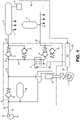
- FIG. 1 is a schematic of the preferred hydraulic circuit for implementing the present invention.
- a dual function pump is shown within the dark, dashed lines, whereby the engine cam 1 reciprocates a plunger 2 within a pumping chamber 3.
- a low pressure feed pump 23 delivers low pressure feed fuel via line 4 through inlet port 22 of the pump into feed passage 19, which is stabilized by accumulator 29.
- Inlet check valve 5 is fluidly connected to the pumping chamber 3 whereby low pressure feed fuel fills the pumping chamber during the retracted or charging stroke of the plunger 2.
- the highly pressurized fuel flows into the discharge passage 15, which has two branches.
- a direct injection passage 16 with associated downstream outlet check valve 7 is in fluid connection with a first pumped fuel outlet 20, for delivery to the common rail 11 in a direct injection mode of operation, supplying the direct injectors 12.
- a second, auxiliary branch line or passage 17 is also fluidly connected to the discharge passage 15 upstream of the first outlet check valve 7.
- a control valve 6 has an inlet side in fluid communication with the auxiliary passage 17 and an outlet side connected to a port injection passage 18 extending through second outlet check valve 9 to a second pumped fuel outlet 21 leading to the port injectors 14.
- the control valve 6 is a directly operated two-way, two position, normally open solenoid valve, which is energized to close.
- a first pressure relief valve 8 is connected between the direct injection passage 16 downstream of the first outlet check valve 7, and the auxiliary passage 17 (or otherwise to the pressure prevailing at the pumping chamber 3).
- a second pressure relief valve 10 is connected between the injection passage 18 downstream of the second outlet check valve 9 and the feed passage 19 or equivalent low inlet or feed pressure region.
- An accumulator 13 is situated in downstream fluid communication with the second outlet check valve 9, to maintain a stable pressure for the port injectors 14 during switching between the PI and DI systems, as will be described in greater detail below.
- the dual function of the GDI pump supports numerous distinct operating conditions or states, providing: (1) low-pressure flow from the feed pump to the PI system and to the DI common rail in the event the HPP pump is inoperable (bypass, or "limp-home” mode); (2) zero flow to the DI common rail or to the PI system; (3) a metered amount of flow at high pressure to the DI common rail; and (4) regulated pressure to the PI system.
- the system is based on the concept that the amount of fuel consumed by the engine is constant for a given operating condition, regardless of the balance of injection through the PI and the DI systems.
- the total amount of fuel consumed for a given generated power is the same regardless of which system, or systems, is being used.
- the preferred strategy is to maintain the desired DI system pressure by metering the pumping volume transferred to the DI system. All remaining pumping volume not transferred to the DI system is transferred to the PI system.
- the PI system target pressure is generally about 10 bar whereas the DI system pressure target is generally about 350 bar.
- the maximum pressure of the PI system is maintained by a pressure regulating scheme of accumulator 13 and second pressure relief valve 10 whereby all excess flow is delivered to the inlet feed passage (4 or 19), and it is fixed for all operating conditions.
- the pump is assumed operable, and all or partial pumping volume is transferred to the PI system.
- control valve 6 is de-energized. Fluid downstream from inlet check valve 5 enters the pumping chamber 3 during the charging cycle. At the end of the charging cycle inlet check valve 5 is closed by the valve bias spring.
- fluid flows through control valve 6, the pressure rises to open the second outlet check valve 9, and fluid is transferred to the PI circuit. Because the DI system operating pressure is higher than the PI system operating pressure, the pumping pressure cannot open the first outlet check valve 7.
- the volume transferred to the PI circuit is limited by the closing of control valve 6. Upon energizing and closing of the control valve 6 the pumping pressure will increase above the opening pressure of the first outlet check valve 7 and all remaining pumping volume is then transferred to the DI circuit.
- the pump is operable and the fuel transferred to the PI system is determined by the closing of control valve 6.
- the valve opens, flowing excess volume from the PI system to the low feed pressure passage 19 or region.
- the configuration is such that the excess flow may occur concurrently with the pumping cycle. Therefore, the amount of fluid transferred to the PI system is dependent only on the PI system pressure, with no metering of transferred volume.
- the pump is assumed operable and all or partial pumping volume is transferred to the DI system.
- control valve 6 is deenergized. Fluid downstream from inlet check valve 5 enters the pumping chamber 3 during the charging cycle. At the end of the charging cycle the inlet check valve 5 is closed by the valve bias spring. During the pumping cycle, control valve 6 is closed. Pumping pressure increases and opens outlet check valve 7 transferring volume to the DI circuit.
- Actuation of control valve 6 is synchronized with the position of the pumping piston. This is achieved by sensing the cam rotational position 24 and processing of that input in the electronic control unit (ECU) 25, which transmits a control signal 26 to the control valve 6.
- ECU electronice control unit
- the only volume transferred is the remaining fluid in the pumping chamber 3 at the time control valve 6 is energized (ignoring losses due to leakage and fluid compressibility).
- the volume transferred to the PI system is limited by the closing of control valve 6.
- the pumping pressure Upon energizing and closing of control valve 6, the pumping pressure will increase above the opening pressure of the first outlet check valve 7. All remaining pumping volume is then transferred to the DI system.
- control valve 6 remains shut, even if the solenoid is de-energized, until the pumping event is complete and the pumping chamber pressure drops to near zero, whereupon the valve opens.
- the pump is assumed operable and the fuel transferred to the PI system is the fuel metered by the closing of control valve 6. As shown in FIG. 6 , when the DI system pressure is above the opening pressure of the pressure relief valve 8, the valve opens draining volume from the DI system to the pumping chamber 3.
- the present invention can provide variable quantity and mode of fuel delivery to one or both of the DI and PI systems. If only a DI system is to be employed, the quantity control or metering of fuel is achieved by the pumping chamber 3 filling with the maximum volume of fuel while the control valve 6 is closed and during the pumping stroke, a quantity of fuel corresponding to a first portion of the pumping stroke is delivered to the common rail 11, until the control valve opens in response to a preselected algorithm or mapping, dependent on the position of the pumping plunger during the pumping stroke.
- the mapping is based in part on sensing 27 of pressure in the common rail 11, with a signal 28 delivered to the ECU 25.
- all or a partial quantity of fuel corresponding to the maximum volume of the pumping chamber can be delivered to the common rail.
- control valve 6 remains open and all of the maximum volume in the pumping chamber is delivered through the control valve 6 and second outlet check valve 9, to the accumulator 13, but as soon as the pressure reaches the set point of the pressure relief valve 10, the quantity of fuel in excess of that corresponding to delivery to the accumulator 13 is passed through the second outlet check valve 10 to a low pressure region.
- the PI system operates at a steady pressure associated with the opening pressure of pressure relief valve 10.
- Both the PI and DI systems can operate concurrently. Usually, the PI system would be pressurized first, followed by the DI system, but the order can be reversed. Although the maximum volume of the pumping chamber is pumped out of the pumping chamber into the discharge line 15, and all of that volume is allocated between the DI system 7, 8, and 16, and the PI system 9, 10, and 18, the respective quantities of fuel delivered to the common rail 11 and accumulator 13, respectively, can total less than the maximum volume of the pumping chamber 3, due to the operation of one or both of the relief valves 8 and 10.
- the pumping chamber 3 fills with fuel to a maximum volume.
- the control valve 6 is open and a first quantity of fuel is pumped through the second outlet check valve 9, corresponding to a first portion of the maximum volume.
- the control valve 6 is closed and a second quantity of fuel is pumped through the first outlet check valve 7, corresponding to a second portion of fuel consisting of all the fuel remaining in the pumping chamber.
- the pumping chamber 3 fills with fuel to a maximum volume.
- the control valve 6 is closed and a first quantity of fuel is pumped through the first outlet check valve 7, corresponding to a first portion of the maximum volume.
- the control valve 6 is open and a second quantity of fuel is pumped through the second outlet check valve 9, corresponding to a second portion of fuel consisting of all the fuel remaining in the pumping chamber.
Landscapes
- Engineering & Computer Science (AREA)
- Chemical & Material Sciences (AREA)
- Combustion & Propulsion (AREA)
- Mechanical Engineering (AREA)
- General Engineering & Computer Science (AREA)
- Fuel-Injection Apparatus (AREA)
Claims (7)
- Kraftstoffpumpe für ein Kraftstoffzufuhrsystem mit einigen Einspritzventilen, die von einer druckbeaufschlagten Verteilerleitung versorgt werden, und anderen Einspritzventilen, die durch Einlasskanäle versorgt werden, und einem elektronischen Steuergerät, wobei die Kraftstoffpumpe Folgendes umfasst:einen Zufuhrdurchgang (19) mit einem Einlassrückschlagventil (5);einen Pumpstempel (2), der in einer Pumpkammer (3), die mit dem Zufuhrdurchgang stromabwärts des Einlassrückschlagventils strömungsverbunden ist, zur Druckbeaufschlagung der Kraftstoffzufuhr hin- und herbewegbar ist;einen Auslassdurchgang (15) von der Pumpkammer zum Zuführen von druckbeaufschlagtem Kraftstoff zu einem ersten Auslassrückschlagventil (7);einen Direkteinspritzungsdurchgang (16), der sich durch das erste Auslassrückschlagventil zur Strömungsverbindung der Pumpe mit der Verteilerleitung (11) erstreckt;einen zusätzlichen Durchgang (17) in Strömungsverbindung mit dem Auslassdurchgang (15) stromaufwärts des ersten Auslassrückschlagventils;ein Steuerventil (6) mit einer Einlassseite in Strömungsverbindung mit dem zusätzlichen Durchgang (17) und einer Auslassseite, wobei das Steuerventil selektiv gegen Strömen durch das Steuerventil schließt oder öffnet, um Strömen durch die Auslassseite des Steuerventils zu gestatten; undeinen Kanaleinspritzungsdurchgang (18) von der Auslassseite des Steuerventils zur Strömungsverbindung der Pumpe mit einem Einlasskanal an einzelnen Einspritzventilen (14) durch ein zweites Auslassrückschlagventil (9), dadurch gekennzeichnet, dassder Pumpstempel einen Ladehub und einen Pumphub aufweist und das Öffnen oder Schließen des Steuerventils als Reaktion auf ein Signal von dem elektronischen Steuergerät (25) entsprechend der Stellung des Stempels während des Pumphubs erfolgt, sich die Pumpkammer (3) während des Ladehubs mit Kraftstoff auf ein maximales Volumen füllt;während eines ersten Teils des Pumphubs das Steuerventil (6) geschlossen ist und eine erste Menge an Kraftstoff, die einem ersten Teil des maximalen Volumens entspricht, durch das erste Auslassrückschlagventil (7) gepumpt wird; undwährend eines zweiten Teils des Pumphubs das Steuerventil (6) geöffnet ist und eine zweite Menge an Kraftstoff, die einem zweiten Teil des Kraftstoffs, der aus dem gesamten in der Pumpkammer verbleibenden Kraftstoff besteht, entspricht, durch das zweite Auslassrückschlagventil (9) gepumpt wird; oderwährend eines ersten Teils des Pumphubs das Steuerventil (6) geöffnet ist und eine erste Menge an Kraftstoff, die einem ersten Teil des maximalen Volumens entspricht, durch das zweite Auslassrückschlagventil (9) gepumpt wird; undwährend eines zweiten Teils des Pumphubs das Steuerventil (6) geschlossen ist und eine zweite Menge an Kraftstoff, die einem zweiten Teil des Kraftstoffs, der aus dem gesamten in der Pumpkammer verbleibenden Kraftstoff besteht, entspricht, durch das erste Auslassrückschlagventil (7) gepumpt wird.
- Kraftstoffpumpe nach Anspruch 1, die Folgendes umfasst:ein erstes Druckablassventil (8), das zwischen dem Direkteinspritzungsdurchgang (16) stromabwärts des ersten Auslassrückschlagventils (7) und einem Strömungspfad in Strömungsverbindung mit der Pumpkammer (3) angeschlossen ist; undein zweites Druckablassventil (10), das zwischen dem Kanaleinspritzungsdurchgang (18) stromabwärts des zweiten Auslassrückschlagventils (9) und dem Zufuhrdurchgang (19) angeschlossen ist.
- Kraftstoffpumpe nach Anspruch 1, wobei in einem Bypassbetriebsmodus:sich der Stempel nicht hin- und herbewegt;Kraftstoff in dem Zufuhrdurchgang (19) mit Zufuhrdruck durch die Pumpkammer (3), den Auslassdurchgang (15), den zusätzlichen Durchgang (17), das Steuerventil (6) und das zweite Auslassrückschlagventil (9) strömt.
- Kraftstoffpumpe nach Anspruch 1, wobei in einem Kanaleinspritzungsbetriebsmodus:der Stempel Kraftstoff aus dem Zufuhrdurchgang mit Druck beaufschlagt;das Steuerventil (6) geöffnet ist; undKraftstoff durch die zusätzliche Leitung (17), das Steuerventil und das zweite Auslassrückschlagventil (9) strömt, während das erste Auslassrückschlagventil (7) geschlossen ist.
- Kraftstoffpumpe nach Anspruch 4, wobei in einem Direkteinspritzungsbetriebsmodus:der Stempel Kraftstoff aus dem Zufuhrkanal mit Druck beaufschlagt;das Steuerventil (6) geschlossen ist, wodurch Strömen von dem zusätzlichen Durchgang (17) zu dem zweiten Auslassrückschlagventil (9) verhindert wird; undmindestens ein Teil des gepumpten Kraftstoffs durch das erste Auslassrückschlagventil (7) strömt.
- Kraftstoffpumpe nach Anspruch 3, wobei in einem Kanaleinspritzungsbetriebsmodus:der Stempel Kraftstoff aus dem Zufuhrdurchgang mit Druck beaufschlagt;das Steuerventil (6) geöffnet ist; undKraftstoff durch die zusätzliche Leitung (17), das Steuerventil und das zweite Auslassrückschlagventil (9) strömt, während das erste Auslassrückschlagventil (7) geschlossen ist; undin einem Direkteinspritzungsbetriebsmodus:der Stempel Kraftstoff aus dem Zufuhrkanal mit Druck beaufschlagt;das Steuerventil (6) geschlossen ist, wodurch Strömen von dem zusätzlichen Durchgang (17) zu dem zweiten Auslassrückschlagventil (9) verhindert wird; undmindestens ein Teil des gepumpten Kraftstoffs durch das erste Auslassrückschlagventil (7) strömt.
- Kraftstoffpumpe nach Anspruch 2, die ferner Folgendes umfasst:
einen Druckspeicher (13), der mit dem zweiten Auslassrückschlagventil (9) in stromabwärtiger Strömungsverbindung steht.
Applications Claiming Priority (2)
| Application Number | Priority Date | Filing Date | Title |
|---|---|---|---|
| US15/797,201 US10450992B2 (en) | 2017-10-30 | 2017-10-30 | GDI pump with direct injection and port injection |
| PCT/US2018/058270 WO2019089637A1 (en) | 2017-10-30 | 2018-10-30 | Gdi pump with direct injection and port injection |
Publications (3)
| Publication Number | Publication Date |
|---|---|
| EP3704371A1 EP3704371A1 (de) | 2020-09-09 |
| EP3704371B1 true EP3704371B1 (de) | 2022-08-31 |
| EP3704371B8 EP3704371B8 (de) | 2022-10-05 |
Family
ID=64402265
Family Applications (1)
| Application Number | Title | Priority Date | Filing Date |
|---|---|---|---|
| EP18807163.3A Active EP3704371B8 (de) | 2017-10-30 | 2018-10-30 | Gdi pumpe mit direkteinspritzung und saugrohreinspritzung |
Country Status (6)
| Country | Link |
|---|---|
| US (1) | US10450992B2 (de) |
| EP (1) | EP3704371B8 (de) |
| JP (1) | JP7244507B2 (de) |
| CN (1) | CN111295508B (de) |
| ES (1) | ES2927083T3 (de) |
| WO (1) | WO2019089637A1 (de) |
Families Citing this family (1)
| Publication number | Priority date | Publication date | Assignee | Title |
|---|---|---|---|---|
| CN116194665A (zh) * | 2020-08-04 | 2023-05-30 | 斯坦蒂内有限责任公司 | 具有低压旁路的高压gdi泵 |
Family Cites Families (15)
| Publication number | Priority date | Publication date | Assignee | Title |
|---|---|---|---|---|
| US7517200B2 (en) | 2004-06-24 | 2009-04-14 | Caterpillar Inc. | Variable discharge fuel pump |
| JP2006017059A (ja) * | 2004-07-02 | 2006-01-19 | Toyota Motor Corp | エンジンの燃料供給装置 |
| JP4466340B2 (ja) * | 2004-11-18 | 2010-05-26 | トヨタ自動車株式会社 | 燃料供給装置 |
| JP4169046B2 (ja) * | 2006-05-23 | 2008-10-22 | トヨタ自動車株式会社 | 内燃機関の制御装置 |
| JP4297160B2 (ja) * | 2006-12-22 | 2009-07-15 | トヨタ自動車株式会社 | 内燃機関 |
| JP5401360B2 (ja) * | 2010-02-26 | 2014-01-29 | 日立オートモティブシステムズ株式会社 | 高圧燃料供給ポンプ |
| DE102010050560A1 (de) | 2010-11-05 | 2012-05-10 | Volkswagen Ag | Kraftstoffhochdruckpumpe für eine Brennkraftmaschine mit Direkteinspritzung |
| DK177456B1 (en) | 2011-06-27 | 2013-06-17 | Man Diesel & Turbo Deutschland | A fuel valve for large turbocharged two stroke diesel engines |
| US9303583B2 (en) * | 2014-01-14 | 2016-04-05 | Ford Global Technologies, Llc | Robust direct injection fuel pump system |
| US9316161B2 (en) * | 2014-04-02 | 2016-04-19 | Ford Global Technologies, Llc | High pressure fuel pumps with mechanical pressure regulation |
| US9683512B2 (en) | 2014-05-23 | 2017-06-20 | Ford Global Technologies, Llc | Pressure device to reduce ticking noise during engine idling |
| BR112017003521B1 (pt) * | 2014-08-21 | 2022-04-05 | Nissan Motor Co., Ltd | Dispositivo de controle de injeção de combustível e método de controle de injeção de combustível para motor de combustão interna |
| US9611801B2 (en) * | 2014-12-15 | 2017-04-04 | Ford Global Technologies, Llc | Methods and systems for fixed and variable pressure fuel injection |
| US9726106B2 (en) * | 2014-12-15 | 2017-08-08 | Ford Global Technologies, Llc | Methods and systems for high pressure port fuel injection |
| US11454189B2 (en) | 2015-06-29 | 2022-09-27 | Ford Global Technologies, Llc | Methods and systems for port fuel injection control |
-
2017
- 2017-10-30 US US15/797,201 patent/US10450992B2/en active Active
-
2018
- 2018-10-30 JP JP2020522920A patent/JP7244507B2/ja active Active
- 2018-10-30 ES ES18807163T patent/ES2927083T3/es active Active
- 2018-10-30 CN CN201880070831.2A patent/CN111295508B/zh active Active
- 2018-10-30 EP EP18807163.3A patent/EP3704371B8/de active Active
- 2018-10-30 WO PCT/US2018/058270 patent/WO2019089637A1/en not_active Ceased
Also Published As
| Publication number | Publication date |
|---|---|
| CN111295508A (zh) | 2020-06-16 |
| CN111295508B (zh) | 2022-05-24 |
| JP7244507B2 (ja) | 2023-03-22 |
| ES2927083T3 (es) | 2022-11-02 |
| EP3704371A1 (de) | 2020-09-09 |
| EP3704371B8 (de) | 2022-10-05 |
| US10450992B2 (en) | 2019-10-22 |
| WO2019089637A1 (en) | 2019-05-09 |
| US20190128208A1 (en) | 2019-05-02 |
| JP2021501282A (ja) | 2021-01-14 |
Similar Documents
| Publication | Publication Date | Title |
|---|---|---|
| EP2964949B1 (de) | Dosierte einzelkolben-kraftstoffpumpe mit elektronisch gesteuertem einlass | |
| US6619263B1 (en) | Fuel injection system for an internal combustion engine | |
| US6253735B1 (en) | Fuel feeding device | |
| US9175650B2 (en) | High-pressure fuel pump for an internal combustion engine with direct injection | |
| US9556836B2 (en) | Pressure relief valve for single plunger fuel pump | |
| US6889657B2 (en) | Fuel injection device for an internal combustion engine | |
| JP2002526716A (ja) | 燃料高圧を生ぜしめるポンプ装置 | |
| JP4437092B2 (ja) | 圧力増幅装置と搬送量を減じられた低圧回路とを備えた燃料噴射装置 | |
| US7527035B2 (en) | Fuel supply system, especially for an internal combustion engine | |
| EP3704371B1 (de) | Gdi pumpe mit direkteinspritzung und saugrohreinspritzung | |
| US20150252768A1 (en) | Constant Pressure Self-Regulating Common Rail Single Piston Pump | |
| US8511414B2 (en) | Fuel system | |
| US7275524B2 (en) | Non-return fuel supply system | |
| CN101517224A (zh) | 发动机的燃料供给装置 | |
| CN103270289B (zh) | 燃料喷射系统的具有设置在泵压力侧的阀的压力调节装置 | |
| CN101631951B (zh) | 用于喷射系统的体积流调节的方法和装置 | |
| CN107288787B (zh) | 燃油喷射系统 | |
| CN111219279B (zh) | 一种具有自保护功能的燃料喷射系统及压力控制方法 | |
| WO1999043941A2 (en) | Diesel pump fuel inlet metering using proportional control valve | |
| JP2021501282A5 (de) | ||
| JP4589039B2 (ja) | 内燃機関の燃料供給装置 | |
| US20190085805A1 (en) | Three stage proportional control valve | |
| JP2007327424A (ja) | 内燃機関の燃料供給装置 |
Legal Events
| Date | Code | Title | Description |
|---|---|---|---|
| STAA | Information on the status of an ep patent application or granted ep patent |
Free format text: STATUS: UNKNOWN |
|
| STAA | Information on the status of an ep patent application or granted ep patent |
Free format text: STATUS: THE INTERNATIONAL PUBLICATION HAS BEEN MADE |
|
| PUAI | Public reference made under article 153(3) epc to a published international application that has entered the european phase |
Free format text: ORIGINAL CODE: 0009012 |
|
| STAA | Information on the status of an ep patent application or granted ep patent |
Free format text: STATUS: REQUEST FOR EXAMINATION WAS MADE |
|
| 17P | Request for examination filed |
Effective date: 20200525 |
|
| AK | Designated contracting states |
Kind code of ref document: A1 Designated state(s): AL AT BE BG CH CY CZ DE DK EE ES FI FR GB GR HR HU IE IS IT LI LT LU LV MC MK MT NL NO PL PT RO RS SE SI SK SM TR |
|
| AX | Request for extension of the european patent |
Extension state: BA ME |
|
| DAV | Request for validation of the european patent (deleted) | ||
| DAX | Request for extension of the european patent (deleted) | ||
| STAA | Information on the status of an ep patent application or granted ep patent |
Free format text: STATUS: EXAMINATION IS IN PROGRESS |
|
| 17Q | First examination report despatched |
Effective date: 20210329 |
|
| GRAP | Despatch of communication of intention to grant a patent |
Free format text: ORIGINAL CODE: EPIDOSNIGR1 |
|
| STAA | Information on the status of an ep patent application or granted ep patent |
Free format text: STATUS: GRANT OF PATENT IS INTENDED |
|
| INTG | Intention to grant announced |
Effective date: 20220413 |
|
| GRAS | Grant fee paid |
Free format text: ORIGINAL CODE: EPIDOSNIGR3 |
|
| GRAA | (expected) grant |
Free format text: ORIGINAL CODE: 0009210 |
|
| STAA | Information on the status of an ep patent application or granted ep patent |
Free format text: STATUS: THE PATENT HAS BEEN GRANTED |
|
| REG | Reference to a national code |
Ref country code: DE Ref legal event code: R081 Ref document number: 602018040079 Country of ref document: DE Owner name: STANADYNE LLC, JACKSONVILLE, US Free format text: FORMER OWNER: STANADYNE LLC, WINDSOR, CT, US |
|
| AK | Designated contracting states |
Kind code of ref document: B1 Designated state(s): AL AT BE BG CH CY CZ DE DK EE ES FI FR GB GR HR HU IE IS IT LI LT LU LV MC MK MT NL NO PL PT RO RS SE SI SK SM TR |
|
| REG | Reference to a national code |
Ref country code: CH Ref legal event code: EP Ref country code: GB Ref legal event code: FG4D |
|
| REG | Reference to a national code |
Ref country code: CH Ref legal event code: PK Free format text: BERICHTIGUNG B8 Ref country code: AT Ref legal event code: REF Ref document number: 1515455 Country of ref document: AT Kind code of ref document: T Effective date: 20220915 |
|
| REG | Reference to a national code |
Ref country code: DE Ref legal event code: R096 Ref document number: 602018040079 Country of ref document: DE |
|
| REG | Reference to a national code |
Ref country code: IE Ref legal event code: FG4D |
|
| RAP4 | Party data changed (patent owner data changed or rights of a patent transferred) |
Owner name: STANADYNE LLC |
|
| REG | Reference to a national code |
Ref country code: ES Ref legal event code: FG2A Ref document number: 2927083 Country of ref document: ES Kind code of ref document: T3 Effective date: 20221102 |
|
| REG | Reference to a national code |
Ref country code: LT Ref legal event code: MG9D |
|
| REG | Reference to a national code |
Ref country code: NL Ref legal event code: MP Effective date: 20220831 |
|
| PG25 | Lapsed in a contracting state [announced via postgrant information from national office to epo] |
Ref country code: SE Free format text: LAPSE BECAUSE OF FAILURE TO SUBMIT A TRANSLATION OF THE DESCRIPTION OR TO PAY THE FEE WITHIN THE PRESCRIBED TIME-LIMIT Effective date: 20220831 Ref country code: RS Free format text: LAPSE BECAUSE OF FAILURE TO SUBMIT A TRANSLATION OF THE DESCRIPTION OR TO PAY THE FEE WITHIN THE PRESCRIBED TIME-LIMIT Effective date: 20220831 Ref country code: NO Free format text: LAPSE BECAUSE OF FAILURE TO SUBMIT A TRANSLATION OF THE DESCRIPTION OR TO PAY THE FEE WITHIN THE PRESCRIBED TIME-LIMIT Effective date: 20221130 Ref country code: LV Free format text: LAPSE BECAUSE OF FAILURE TO SUBMIT A TRANSLATION OF THE DESCRIPTION OR TO PAY THE FEE WITHIN THE PRESCRIBED TIME-LIMIT Effective date: 20220831 Ref country code: LT Free format text: LAPSE BECAUSE OF FAILURE TO SUBMIT A TRANSLATION OF THE DESCRIPTION OR TO PAY THE FEE WITHIN THE PRESCRIBED TIME-LIMIT Effective date: 20220831 Ref country code: FI Free format text: LAPSE BECAUSE OF FAILURE TO SUBMIT A TRANSLATION OF THE DESCRIPTION OR TO PAY THE FEE WITHIN THE PRESCRIBED TIME-LIMIT Effective date: 20220831 |
|
| REG | Reference to a national code |
Ref country code: AT Ref legal event code: MK05 Ref document number: 1515455 Country of ref document: AT Kind code of ref document: T Effective date: 20220831 |
|
| PG25 | Lapsed in a contracting state [announced via postgrant information from national office to epo] |
Ref country code: PL Free format text: LAPSE BECAUSE OF FAILURE TO SUBMIT A TRANSLATION OF THE DESCRIPTION OR TO PAY THE FEE WITHIN THE PRESCRIBED TIME-LIMIT Effective date: 20220831 Ref country code: IS Free format text: LAPSE BECAUSE OF FAILURE TO SUBMIT A TRANSLATION OF THE DESCRIPTION OR TO PAY THE FEE WITHIN THE PRESCRIBED TIME-LIMIT Effective date: 20221231 Ref country code: HR Free format text: LAPSE BECAUSE OF FAILURE TO SUBMIT A TRANSLATION OF THE DESCRIPTION OR TO PAY THE FEE WITHIN THE PRESCRIBED TIME-LIMIT Effective date: 20220831 Ref country code: GR Free format text: LAPSE BECAUSE OF FAILURE TO SUBMIT A TRANSLATION OF THE DESCRIPTION OR TO PAY THE FEE WITHIN THE PRESCRIBED TIME-LIMIT Effective date: 20221201 |
|
| PG25 | Lapsed in a contracting state [announced via postgrant information from national office to epo] |
Ref country code: SM Free format text: LAPSE BECAUSE OF FAILURE TO SUBMIT A TRANSLATION OF THE DESCRIPTION OR TO PAY THE FEE WITHIN THE PRESCRIBED TIME-LIMIT Effective date: 20220831 Ref country code: RO Free format text: LAPSE BECAUSE OF FAILURE TO SUBMIT A TRANSLATION OF THE DESCRIPTION OR TO PAY THE FEE WITHIN THE PRESCRIBED TIME-LIMIT Effective date: 20220831 Ref country code: PT Free format text: LAPSE BECAUSE OF FAILURE TO SUBMIT A TRANSLATION OF THE DESCRIPTION OR TO PAY THE FEE WITHIN THE PRESCRIBED TIME-LIMIT Effective date: 20230102 Ref country code: DK Free format text: LAPSE BECAUSE OF FAILURE TO SUBMIT A TRANSLATION OF THE DESCRIPTION OR TO PAY THE FEE WITHIN THE PRESCRIBED TIME-LIMIT Effective date: 20220831 Ref country code: CZ Free format text: LAPSE BECAUSE OF FAILURE TO SUBMIT A TRANSLATION OF THE DESCRIPTION OR TO PAY THE FEE WITHIN THE PRESCRIBED TIME-LIMIT Effective date: 20220831 Ref country code: AT Free format text: LAPSE BECAUSE OF FAILURE TO SUBMIT A TRANSLATION OF THE DESCRIPTION OR TO PAY THE FEE WITHIN THE PRESCRIBED TIME-LIMIT Effective date: 20220831 |
|
| PG25 | Lapsed in a contracting state [announced via postgrant information from national office to epo] |
Ref country code: SK Free format text: LAPSE BECAUSE OF FAILURE TO SUBMIT A TRANSLATION OF THE DESCRIPTION OR TO PAY THE FEE WITHIN THE PRESCRIBED TIME-LIMIT Effective date: 20220831 Ref country code: MC Free format text: LAPSE BECAUSE OF FAILURE TO SUBMIT A TRANSLATION OF THE DESCRIPTION OR TO PAY THE FEE WITHIN THE PRESCRIBED TIME-LIMIT Effective date: 20220831 Ref country code: EE Free format text: LAPSE BECAUSE OF FAILURE TO SUBMIT A TRANSLATION OF THE DESCRIPTION OR TO PAY THE FEE WITHIN THE PRESCRIBED TIME-LIMIT Effective date: 20220831 |
|
| REG | Reference to a national code |
Ref country code: CH Ref legal event code: PL |
|
| REG | Reference to a national code |
Ref country code: DE Ref legal event code: R097 Ref document number: 602018040079 Country of ref document: DE |
|
| REG | Reference to a national code |
Ref country code: BE Ref legal event code: MM Effective date: 20221031 |
|
| PG25 | Lapsed in a contracting state [announced via postgrant information from national office to epo] |
Ref country code: NL Free format text: LAPSE BECAUSE OF FAILURE TO SUBMIT A TRANSLATION OF THE DESCRIPTION OR TO PAY THE FEE WITHIN THE PRESCRIBED TIME-LIMIT Effective date: 20220831 Ref country code: LU Free format text: LAPSE BECAUSE OF NON-PAYMENT OF DUE FEES Effective date: 20221030 Ref country code: AL Free format text: LAPSE BECAUSE OF FAILURE TO SUBMIT A TRANSLATION OF THE DESCRIPTION OR TO PAY THE FEE WITHIN THE PRESCRIBED TIME-LIMIT Effective date: 20220831 |
|
| P01 | Opt-out of the competence of the unified patent court (upc) registered |
Effective date: 20230525 |
|
| PLBE | No opposition filed within time limit |
Free format text: ORIGINAL CODE: 0009261 |
|
| STAA | Information on the status of an ep patent application or granted ep patent |
Free format text: STATUS: NO OPPOSITION FILED WITHIN TIME LIMIT |
|
| PG25 | Lapsed in a contracting state [announced via postgrant information from national office to epo] |
Ref country code: LI Free format text: LAPSE BECAUSE OF NON-PAYMENT OF DUE FEES Effective date: 20221031 Ref country code: CH Free format text: LAPSE BECAUSE OF NON-PAYMENT OF DUE FEES Effective date: 20221031 |
|
| 26N | No opposition filed |
Effective date: 20230601 |
|
| PG25 | Lapsed in a contracting state [announced via postgrant information from national office to epo] |
Ref country code: SI Free format text: LAPSE BECAUSE OF FAILURE TO SUBMIT A TRANSLATION OF THE DESCRIPTION OR TO PAY THE FEE WITHIN THE PRESCRIBED TIME-LIMIT Effective date: 20220831 |
|
| PG25 | Lapsed in a contracting state [announced via postgrant information from national office to epo] |
Ref country code: BE Free format text: LAPSE BECAUSE OF NON-PAYMENT OF DUE FEES Effective date: 20221031 |
|
| PG25 | Lapsed in a contracting state [announced via postgrant information from national office to epo] |
Ref country code: IE Free format text: LAPSE BECAUSE OF NON-PAYMENT OF DUE FEES Effective date: 20221030 |
|
| PG25 | Lapsed in a contracting state [announced via postgrant information from national office to epo] |
Ref country code: CY Free format text: LAPSE BECAUSE OF FAILURE TO SUBMIT A TRANSLATION OF THE DESCRIPTION OR TO PAY THE FEE WITHIN THE PRESCRIBED TIME-LIMIT Effective date: 20220831 |
|
| PG25 | Lapsed in a contracting state [announced via postgrant information from national office to epo] |
Ref country code: MK Free format text: LAPSE BECAUSE OF FAILURE TO SUBMIT A TRANSLATION OF THE DESCRIPTION OR TO PAY THE FEE WITHIN THE PRESCRIBED TIME-LIMIT Effective date: 20220831 Ref country code: HU Free format text: LAPSE BECAUSE OF FAILURE TO SUBMIT A TRANSLATION OF THE DESCRIPTION OR TO PAY THE FEE WITHIN THE PRESCRIBED TIME-LIMIT; INVALID AB INITIO Effective date: 20181030 |
|
| PG25 | Lapsed in a contracting state [announced via postgrant information from national office to epo] |
Ref country code: BG Free format text: LAPSE BECAUSE OF FAILURE TO SUBMIT A TRANSLATION OF THE DESCRIPTION OR TO PAY THE FEE WITHIN THE PRESCRIBED TIME-LIMIT Effective date: 20220831 |
|
| PG25 | Lapsed in a contracting state [announced via postgrant information from national office to epo] |
Ref country code: MT Free format text: LAPSE BECAUSE OF FAILURE TO SUBMIT A TRANSLATION OF THE DESCRIPTION OR TO PAY THE FEE WITHIN THE PRESCRIBED TIME-LIMIT Effective date: 20220831 |
|
| PGFP | Annual fee paid to national office [announced via postgrant information from national office to epo] |
Ref country code: DE Payment date: 20241029 Year of fee payment: 7 |
|
| PGFP | Annual fee paid to national office [announced via postgrant information from national office to epo] |
Ref country code: GB Payment date: 20241028 Year of fee payment: 7 |
|
| PGFP | Annual fee paid to national office [announced via postgrant information from national office to epo] |
Ref country code: FR Payment date: 20241025 Year of fee payment: 7 |
|
| PGFP | Annual fee paid to national office [announced via postgrant information from national office to epo] |
Ref country code: IT Payment date: 20241021 Year of fee payment: 7 Ref country code: ES Payment date: 20241104 Year of fee payment: 7 |