EP3703891B1 - Cutting head and rotary cutting tool having same releasably clamped to a shank via a locating pin - Google Patents
Cutting head and rotary cutting tool having same releasably clamped to a shank via a locating pin Download PDFInfo
- Publication number
- EP3703891B1 EP3703891B1 EP18797164.3A EP18797164A EP3703891B1 EP 3703891 B1 EP3703891 B1 EP 3703891B1 EP 18797164 A EP18797164 A EP 18797164A EP 3703891 B1 EP3703891 B1 EP 3703891B1
- Authority
- EP
- European Patent Office
- Prior art keywords
- head
- shank
- tool
- rotary cutting
- clamping
- Prior art date
- Legal status (The legal status is an assumption and is not a legal conclusion. Google has not performed a legal analysis and makes no representation as to the accuracy of the status listed.)
- Active
Links
Images


Classifications
-
- B—PERFORMING OPERATIONS; TRANSPORTING
- B23—MACHINE TOOLS; METAL-WORKING NOT OTHERWISE PROVIDED FOR
- B23B—TURNING; BORING
- B23B31/00—Chucks; Expansion mandrels; Adaptations thereof for remote control
- B23B31/02—Chucks
- B23B31/10—Chucks characterised by the retaining or gripping devices or their immediate operating means
- B23B31/107—Retention by laterally-acting detents, e.g. pins, screws, wedges; Retention by loose elements, e.g. balls
- B23B31/1075—Retention by screws
- B23B31/1076—Retention by screws with conical ends
-
- B—PERFORMING OPERATIONS; TRANSPORTING
- B23—MACHINE TOOLS; METAL-WORKING NOT OTHERWISE PROVIDED FOR
- B23B—TURNING; BORING
- B23B51/00—Tools for drilling machines
-
- B—PERFORMING OPERATIONS; TRANSPORTING
- B23—MACHINE TOOLS; METAL-WORKING NOT OTHERWISE PROVIDED FOR
- B23B—TURNING; BORING
- B23B51/00—Tools for drilling machines
- B23B51/06—Drills with lubricating or cooling equipment
-
- B—PERFORMING OPERATIONS; TRANSPORTING
- B23—MACHINE TOOLS; METAL-WORKING NOT OTHERWISE PROVIDED FOR
- B23B—TURNING; BORING
- B23B2250/00—Compensating adverse effects during turning, boring or drilling
- B23B2250/12—Cooling and lubrication
-
- B—PERFORMING OPERATIONS; TRANSPORTING
- B23—MACHINE TOOLS; METAL-WORKING NOT OTHERWISE PROVIDED FOR
- B23B—TURNING; BORING
- B23B2251/00—Details of tools for drilling machines
- B23B2251/02—Connections between shanks and removable cutting heads
-
- Y—GENERAL TAGGING OF NEW TECHNOLOGICAL DEVELOPMENTS; GENERAL TAGGING OF CROSS-SECTIONAL TECHNOLOGIES SPANNING OVER SEVERAL SECTIONS OF THE IPC; TECHNICAL SUBJECTS COVERED BY FORMER USPC CROSS-REFERENCE ART COLLECTIONS [XRACs] AND DIGESTS
- Y10—TECHNICAL SUBJECTS COVERED BY FORMER USPC
- Y10T—TECHNICAL SUBJECTS COVERED BY FORMER US CLASSIFICATION
- Y10T408/00—Cutting by use of rotating axially moving tool
- Y10T408/44—Cutting by use of rotating axially moving tool with means to apply transient, fluent medium to work or product
- Y10T408/45—Cutting by use of rotating axially moving tool with means to apply transient, fluent medium to work or product including Tool with duct
- Y10T408/455—Conducting channel extending to end of Tool
-
- Y—GENERAL TAGGING OF NEW TECHNOLOGICAL DEVELOPMENTS; GENERAL TAGGING OF CROSS-SECTIONAL TECHNOLOGIES SPANNING OVER SEVERAL SECTIONS OF THE IPC; TECHNICAL SUBJECTS COVERED BY FORMER USPC CROSS-REFERENCE ART COLLECTIONS [XRACs] AND DIGESTS
- Y10—TECHNICAL SUBJECTS COVERED BY FORMER USPC
- Y10T—TECHNICAL SUBJECTS COVERED BY FORMER US CLASSIFICATION
- Y10T408/00—Cutting by use of rotating axially moving tool
- Y10T408/89—Tool or Tool with support
- Y10T408/909—Having peripherally spaced cutting edges
- Y10T408/9098—Having peripherally spaced cutting edges with means to retain Tool to support
- Y10T408/90993—Screw driven means
Definitions
- the female and male members may not be in radial abutment with each other, in the locked position.
- the locating pin projects from the first head end surface.
- the plurality of head flutes may not continue onto the locating pin.
- the head and shank axial abutment surfaces can be planar, and can extend perpendicularly to the tool central axis.
- the cutting head and the tool shank can have the same hardness.
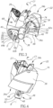
- a rotary cutting tool 20 of the type used for drilling operations, in accordance with embodiments of the subject matter of the present application.
- the rotary cutting tool 20 is a drilling tool for drilling holes.
- the rotary cutting tool 20 has a tool central axis A that defines opposite forward and rearward directions D F , D R .
- the rotary cutting tool 20 is rotatable about the tool central axis A in a rotational direction R.
- the rotary cutting tool 20 can exhibit rotational symmetry about the tool central axis A.
- the rotary cutting tool 20 exhibits 180° rotational symmetry about the tool central axis A.
- the rotary cutting tool 20 includes two parts, namely, a cutting head 22 and a complementary tool shank 24 releasably clampable thereto. Both said parts can typically be made from the same material, e.g. steel. Thus, both parts can have the same hardness. At least one cutting insert 26 is releasably attached to the cutting head 22 in an insert pocket 27 located on the tool shank 24.
- the rotary cutting tool 20 is thus modular. In this non-limiting example shown in the drawings, the rotary cutting tool 20 includes three cutting inserts 26 where one of the cutting insert 26 is centrally disposed and the other cutting inserts 26 are peripherally disposed.
- the rotary cutting tool 20 can have a single cutting insert having a single, continuous cutting edge that extends over the full diametric extent of the rotary cutting tool 20.
- Each cutting insert 26 can be typically made from cemented carbide and is attached in the pocket 27 that is located at a forward end of the cutting head 22.
- the rotary cutting tool 20 is adjustable between a released and locked position. In the locked position of the rotary cutting tool 20, the cutting head is releasably clamped to the tool shank 24, by at least one clamping member 28.
- the cutting head 22 includes opposite first and second head end surfaces 34a, 34b and a head peripheral surface 36 that extends therebetween.
- the head peripheral surface 36 extends circumferentially about the tool central axis A, and forms a boundary of the first and second head end surfaces 34a, 34b.
- the tool central axis A intersects the first and second head end surfaces 34a, 34b.
- the cutting head 22 has its own head central axis B, that is co-incident with the tool central axis A when the rotary cutting tool 20 is in the locked position.
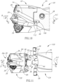
- the tool shank 24 includes opposite first and second shank end surfaces 76a, 76b and a shank peripheral surface 78 that extends therebetween.
- the shank peripheral surface 78 extends circumferentially about the tool central axis A, and forms a boundary of the first and second shank end surfaces 76a, 76b.
- the tool central axis A intersects the first and second shank end surfaces 76a, 76b.
- the tool shank 24 has its own shank central axis C, that is co-incident with the tool central axis A when the rotary cutting tool 20 is in the locked position.
- the locating pin 38 can project from the first shank end surface 76a.
- the purpose of the locating pin 38 is two-fold. Firstly, to position the cutting head 22 in a precise predetermined position relative to the tool shank 24.
- the pin peripheral surface 44 includes at least one clamping recess 46.
- the at least one clamping recess 46 is peripherally disposed on the locating pin 38.
- the at least one clamping recess 46 is designed for receiving a portion of a respective clamping member 28.
- the number of clamping recesses 46 matches the number of clamping members 28.
- the locating pin 38 can include exactly two clamping recess 46 that can be arranged diametrically opposite each other.
- Each clamping recess 46 can be spaced apart from the pin rear surface 42.
- each clamping recess 46 can be spaced apart from the first head end surface 34a.
- Each clamping recess 46 can include a clamping recess inner peripheral surface 48 that extends from the pin peripheral surface 44.
- the clamping recess inner peripheral surface 48 can have a generally frusto-conical shape.
- Each clamping recess inner peripheral surface 48 can include a clamping recess abutment surface 50 for contact with the clamping member 28.
- the clamping recess abutment surface 50 can be planar.
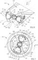
- the cutting head 22 includes a plurality of head driven surfaces 52 which are circumferentially spaced apart from each other and radially inwardly spaced apart from the head peripheral surface 36.
- Each head driven surface 52 is arranged eccentrically with respect to the tool central axis A.
- Each head driven surface 52 faces generally in a first circumferential direction C1 that corresponds to a direction opposite the rotational direction R.
- each head driven surface 52 can be planar and extend parallel to the tool central axis A.
- the first head end surface 34a can include a plurality of circumferentially spaced apart female members 54 recessed therein.
- the first head end surface 34a can include exactly two female members 54 that can be arranged diametrically opposite each other.
- Each head driven surface 52 can be located in a respective one of the plurality of female members 54.
- Each female member 54 can open out to the first head end surface 34a at a female member opening surface 56.
- the female member opening surface 56 can be chamfered.
- each female member 54 can include a female member inner peripheral surface 58 that extends circumferentially about a female member axis D and that forms a boundary of a female member bottom surface 60 disposed axially opposite the female member opening surface 56.
- the female member axis D can be parallel to the tool central axis A.
- Each female member 54 can have a non-circular radial cross-section in a plane perpendicular to the female member axis D.
- the female member inner peripheral surface 58 can include rotationally opposite female member side surfaces 62a, 62b and radially opposite female member inner and outer surfaces 64a, 64b connecting the female member side surfaces 62a, 62b.
- the female member inner surface 64a can be convexly curved and the female member outer surface 64b can be concavely curved in a circumferential direction C1, C2.
- the female members 54 can have a basic kidney-shaped profile in an end view (i.e. Fig. 5 ).
- the cutting head 22 includes a head axial abutment surface 66 located on the first head end surface 34a.
- the head axial abutment surface 66 is for abutting a corresponding surface on the tool shank 24.
- the head axial abutment surface 66 can be disposed axially between the plurality of head driven surfaces 52 and the locating pin 38, respectively.
- the head axial abutment surface 66 can extend radially outwardly to the head peripheral surface 36.
- the locating pin base surface 40 can be completely bounded by the head axial abutment surface 66.
- each female member opening surface 56 can be completely bounded by the head axial abutment surface 66.
- the female members 54 are radially inwardly spaced apart from the head peripheral surface 36 by a narrow head strip portion 35 of the first head end surface 34a.
- the plurality of female members 54 can be spaced apart from the locating pin 38 and the head peripheral surface 36.
- the head axial abutment surface 66 can be planar and extend perpendicularly to the tool central axis A.
- the head peripheral surface 36 can include a plurality of head flutes 68 that extend helically about the tool central axis A.
- the head flutes 68 are designed for chip evacuation.
- the plurality of head flutes 68 can extend from the second head send surface 34b to the first head end surface 34a.
- the plurality of head flutes 68 generally do not continue onto the locating pin 38.
- the plurality of head flutes 68 can form a plurality of cutting arms 70 that can extend radially outwardly.
- Each cutting arm 70 is formed between two adjacent head flutes 68 and includes rotationally opposite cutting leading and trailing surfaces 72a, 72b.
- Each of the cutting inserts 26 can be releasably attached at a respective one of the plurality of cutting arms 70.
- each female member 54 can be located at a cutting arm 70. As see in Fig.
- the rotary cutting tool 20 includes at least one clamping through bore 84 formed in whichever one of the head peripheral surface 36 and the shank peripheral surface 78 the pin receptacle 80 is recessed, so that the clamping through bore 84 opens out to the pin receptacle 80 (i.e. the at least one clamping through bore 84 is formed on the same part as the pin receptacle 80 ).
- the clamping through bore 84 is designed to receive the clamping member 28 as discussed later in the description.
- the number of clamping through bores 84 matches the number of clamping members 28.
- the rotary cutting tool 20 can include exactly two clamping through bores 84 that can be arranged diametrically opposite each other.
- Each clamping through bore 84 can include an internal threaded portion 86.
- the first shank end surface 76a can include a plurality of circumferentially spaced apart male members 90 projecting therefrom.
- the male members 90 are radially inwardly spaced apart from the shank peripheral surface 78 by a narrow shank strip portion 77 of the first shank end surface 76a.
- no surface formed of the male members 90 can be considered an axial extension of the shank peripheral surface 78.
- the first shank end surface 76a can include exactly two male members 90 arranged diametrically opposite each other.
- Each male member 90 is integrally formed with the tool shank 24 to have unitary one-piece construction therewith.
- Each shank driving surface 88 can be located on a respective one of the plurality of male members 90.
- Each male member 90 can project from the first shank end surface 76a at a male member base surface 92.
- the male member base surface 92 can have a radius.
- each male member 90 can include a male member outer peripheral surface 94 that extends circumferentially about a male member axis E and that forms a boundary of a male member top surface 96 disposed axially opposite the male member base surface 92.
- the male member axis E can be parallel to the tool central axis A.
- Each male member 90 can have a non-circular radial cross-section in a plane perpendicular to male member axis E.
- the male member outer peripheral surface 94 can include rotationally opposite male member side surfaces 98a, 98b and radially opposite male member inner and outer surfaces 100a, 100b connecting the male member side surfaces 98a, 98b.
- the male member inner surface 100a can be concavely curved and the male member outer surface 100b can be convexly curved, both in a circumferential direction C1, C2.
- the male members 90 can have a basic kidney-shaped profile in an end view (i.e. Fig. 7 ).
- the cutting head 122 formed with the pin receptacle 80 and the plurality of male members 90 has a minimum length defined by the length of the pin receptacle 80.
- the tool shank 24 can be formed of multiple parts coupled together via a coupling mechanism of the type described above.
Landscapes
- Engineering & Computer Science (AREA)
- Mechanical Engineering (AREA)
- Milling Processes (AREA)
- Drilling Tools (AREA)
- Gripping On Spindles (AREA)
Applications Claiming Priority (2)
| Application Number | Priority Date | Filing Date | Title |
|---|---|---|---|
| US15/801,619 US10569346B2 (en) | 2017-11-02 | 2017-11-02 | Cutting head and rotary cutting tool having same releasably clamped to a shank via a locating pin |
| PCT/IL2018/051095 WO2019087177A1 (en) | 2017-11-02 | 2018-10-10 | Cutting head and rotary cutting tool having same releasably clamped to a shank via a locating pin |
Publications (2)
| Publication Number | Publication Date |
|---|---|
| EP3703891A1 EP3703891A1 (en) | 2020-09-09 |
| EP3703891B1 true EP3703891B1 (en) | 2024-07-10 |
Family
ID=64109980
Family Applications (1)
| Application Number | Title | Priority Date | Filing Date |
|---|---|---|---|
| EP18797164.3A Active EP3703891B1 (en) | 2017-11-02 | 2018-10-10 | Cutting head and rotary cutting tool having same releasably clamped to a shank via a locating pin |
Country Status (13)
| Country | Link |
|---|---|
| US (1) | US10569346B2 (pl) |
| EP (1) | EP3703891B1 (pl) |
| JP (1) | JP7203841B2 (pl) |
| KR (1) | KR102531284B1 (pl) |
| CN (1) | CN111278591B (pl) |
| BR (1) | BR112020008491B1 (pl) |
| CA (1) | CA3079146A1 (pl) |
| ES (1) | ES2992903T3 (pl) |
| IL (1) | IL273880B2 (pl) |
| PL (1) | PL3703891T3 (pl) |
| PT (1) | PT3703891T (pl) |
| TW (1) | TWI761574B (pl) |
| WO (1) | WO2019087177A1 (pl) |
Families Citing this family (10)
| Publication number | Priority date | Publication date | Assignee | Title |
|---|---|---|---|---|
| US11235397B2 (en) | 2016-12-16 | 2022-02-01 | Kennametal Inc. | Side-activated modular drill |
| DE102019116160A1 (de) | 2018-06-20 | 2019-12-24 | Kennametal Inc. | Seitlich geschlossener modularer Bohrer mit federunterstütztem Auswurf |
| US11471952B2 (en) | 2020-03-19 | 2022-10-18 | Kennametal Inc. | Cutting tool having replaceable cutting head and method of securing a replaceable cutting head |
| USD1009108S1 (en) | 2020-09-21 | 2023-12-26 | Kyocera Unimerco Tooling A/S | Drill |
| CN112705759A (zh) * | 2020-12-21 | 2021-04-27 | 绵阳市绵工工具有限公司 | 分体式钻具 |
| US11883888B2 (en) | 2021-06-28 | 2024-01-30 | Kennametal Inc. | Modular drill with enhanced bump-off capability |
| US11839920B2 (en) | 2021-06-28 | 2023-12-12 | Kennametal Inc. | Modular drill and method for using a modular drill |
| US11919094B2 (en) | 2021-07-20 | 2024-03-05 | Kennametal Inc. | Modular drill apparatus with cutting tip in situ insert assembly |
| US12128484B2 (en) | 2022-07-20 | 2024-10-29 | Kennametal Inc. | Cutting tool with modular pocket wall |
| KR102906002B1 (ko) * | 2025-03-13 | 2025-12-30 | (주)제이디테크 | 캘리퍼 하우징 가공용 3단 보링 홀더 |
Citations (1)
| Publication number | Priority date | Publication date | Assignee | Title |
|---|---|---|---|---|
| US6109841A (en) * | 1995-11-07 | 2000-08-29 | Johne & Co., Prazisionswerkzeuge GmbH | Drilling tool with replaceable bit |
Family Cites Families (36)
| Publication number | Priority date | Publication date | Assignee | Title |
|---|---|---|---|---|
| US2259611A (en) | 1941-03-19 | 1941-10-21 | George M Burger | Drill |
| FR2495978A1 (fr) * | 1980-12-12 | 1982-06-18 | Renault | Dispositif de montage de porte-outil sur un element de machine |
| US4971491A (en) * | 1985-10-15 | 1990-11-20 | Cook Harold D | Tool holder system and method of use |
| SE500251C2 (sv) * | 1991-11-08 | 1994-05-24 | Seco Tools Ab | Skaft för olika typer av kopplingar samt koppling för anslutning av detta till en fräs. |
| US6012881A (en) | 1995-03-03 | 2000-01-11 | Komet Praezisionswerkzeuge Robert Breuning Gmbh | Drilling tool |
| IL120948A0 (en) * | 1997-05-29 | 1997-09-30 | Iscar Ltd | Cutting tool assembly |
| IL127895A (en) | 1998-12-31 | 2001-08-26 | Iscar Ltd | Tool assembly |
| US6604894B1 (en) * | 2002-03-08 | 2003-08-12 | Valenite Inc. | Rotatable cutting tool |
| JP2003291015A (ja) * | 2002-03-29 | 2003-10-14 | Mitsubishi Materials Corp | スローアウェイ式ドリル |
| DE10314889A1 (de) | 2003-04-01 | 2004-10-14 | Komet Group Holding Gmbh | Werkzeug für Werkzeugmaschinen |
| KR20050011352A (ko) * | 2003-07-23 | 2005-01-29 | 한국야금 주식회사 | 보링바아의 선단 헤드부 결합장치 |
| EP1533061A1 (en) * | 2003-11-11 | 2005-05-25 | Yestool Co., Ltd. | Structure for securing insert to insert drill |
| US7244081B2 (en) | 2004-09-09 | 2007-07-17 | Ingersoll Cutting Tool Company | Drill adapter for drill having central and lateral cutting inserts |
| DE502007000132D1 (de) * | 2006-02-13 | 2008-11-13 | Kaiser Heinz Ag | Werkzeug für die spahnabhebende Bearbeitung |
| DE102006012382A1 (de) * | 2006-03-17 | 2007-09-20 | Kennametal Inc. | Drehwerkzeug, insbesondere Bohrwerkzeug sowie Werkzeugkopf für ein Drehwerkzeug |
| KR100888041B1 (ko) * | 2007-05-09 | 2009-03-09 | 대구텍 주식회사 | 툴 조립체 |
| JP5061775B2 (ja) * | 2007-08-03 | 2012-10-31 | 株式会社タンガロイ | 切削工具 |
| AU2009231230A1 (en) | 2008-04-03 | 2009-10-08 | Kennametal Inc. | Lathe tool, in particular boring tool |
| SE533652C2 (sv) | 2008-04-14 | 2010-11-23 | Seco Tools Ab | Verktyg för roterande skärande bearbetning med utbytbart skärhuvud |
| DE102009013580A1 (de) | 2009-03-19 | 2010-09-23 | EMUGE-Werk Richard Glimpel GmbH & Co. KG Fabrik für Präzisionswerkzeuge | Modularer Bohrer |
| KR101021963B1 (ko) | 2009-04-14 | 2011-03-16 | 윤성덕 | 교체형 볼커터헤드가 구비된 인덱서블 커터 |
| SE534645C2 (sv) * | 2009-11-10 | 2011-11-01 | Sandvik Intellectual Property | Roterbart verktyg för spånavskiljande bearbetning samt löstopp och grundkropp härför |
| IL204009A (en) * | 2010-02-17 | 2013-11-28 | Iscar Ltd | Cutting and cutting tools |
| DE102010044273B4 (de) | 2010-09-02 | 2012-10-11 | Jürgen Mettchen | Universalschnittstelle für die maschinelle spanabhebende Materialbearbeitung |
| CN103118823B (zh) * | 2010-09-30 | 2016-03-02 | 株式会社钨钛合金 | 刀尖更换式切削工具 |
| IL210893A (en) * | 2011-01-26 | 2015-01-29 | Iscar Ltd | Cutting Tools |
| JP5845816B2 (ja) * | 2011-10-31 | 2016-01-20 | 三菱マテリアル株式会社 | 先端部交換式切削工具 |
| US9498829B2 (en) | 2013-03-06 | 2016-11-22 | Allied Machine & Engineering Corp. | Drilling system for deep holes |
| DE102013205889B3 (de) * | 2013-04-03 | 2014-05-28 | Kennametal Inc. | Kupplungsteil, insbesondere Schneidkopf für ein Rotationswerkzeug sowie ein derartiges Rotationswerkzeug |
| EP2883640B1 (en) * | 2013-12-13 | 2017-05-17 | Sandvik Intellectual Property AB | Cutting tool with abutment members and toolholder and cutting insert therefor |
| DE102014206796B4 (de) * | 2014-04-08 | 2020-10-15 | Kennametal Inc. | Rotationswerkzeug, insbesondere Bohrer sowie Schneidkopf für ein solches Rotationswerkzeug |
| DE102014209135B3 (de) * | 2014-05-14 | 2015-11-05 | Kennametal Inc. | Werkzeugkopf und Rotationswerkzeug mit einem solchen |
| DE102014108219B4 (de) * | 2014-06-12 | 2020-12-17 | Kennametal Inc. | Rotationswerkzeug sowie Verfahren zur Herstellung eines Rotationswerkzeugs |
| US9468979B2 (en) * | 2014-06-17 | 2016-10-18 | Iscar, Ltd. | Rotary cutting tool including cutting head having coupling pin with guiding and fastening recesses |
| US10766077B2 (en) * | 2016-03-04 | 2020-09-08 | Sumitomo Electric Hardmetal Corp. | Cutting tool |
| US10799958B2 (en) * | 2017-08-21 | 2020-10-13 | Kennametal Inc. | Modular rotary cutting tool |
-
2017
- 2017-11-02 US US15/801,619 patent/US10569346B2/en active Active
-
2018
- 2018-08-16 TW TW107128555A patent/TWI761574B/zh active
- 2018-10-10 PT PT187971643T patent/PT3703891T/pt unknown
- 2018-10-10 CN CN201880071005.XA patent/CN111278591B/zh active Active
- 2018-10-10 CA CA3079146A patent/CA3079146A1/en active Pending
- 2018-10-10 EP EP18797164.3A patent/EP3703891B1/en active Active
- 2018-10-10 JP JP2020522829A patent/JP7203841B2/ja active Active
- 2018-10-10 PL PL18797164.3T patent/PL3703891T3/pl unknown
- 2018-10-10 KR KR1020207011782A patent/KR102531284B1/ko active Active
- 2018-10-10 ES ES18797164T patent/ES2992903T3/es active Active
- 2018-10-10 WO PCT/IL2018/051095 patent/WO2019087177A1/en not_active Ceased
- 2018-10-10 IL IL273880A patent/IL273880B2/en unknown
- 2018-10-10 BR BR112020008491-3A patent/BR112020008491B1/pt active IP Right Grant
Patent Citations (1)
| Publication number | Priority date | Publication date | Assignee | Title |
|---|---|---|---|---|
| US6109841A (en) * | 1995-11-07 | 2000-08-29 | Johne & Co., Prazisionswerkzeuge GmbH | Drilling tool with replaceable bit |
Also Published As
| Publication number | Publication date |
|---|---|
| BR112020008491A2 (pt) | 2020-10-20 |
| US20190126361A1 (en) | 2019-05-02 |
| IL273880B1 (en) | 2023-11-01 |
| CA3079146A1 (en) | 2019-05-09 |
| JP7203841B2 (ja) | 2023-01-13 |
| KR20200072487A (ko) | 2020-06-22 |
| EP3703891A1 (en) | 2020-09-09 |
| RU2020113893A3 (pl) | 2022-02-08 |
| TW201934227A (zh) | 2019-09-01 |
| CN111278591A (zh) | 2020-06-12 |
| WO2019087177A1 (en) | 2019-05-09 |
| KR102531284B1 (ko) | 2023-05-12 |
| ES2992903T3 (en) | 2024-12-19 |
| IL273880B2 (en) | 2024-03-01 |
| IL273880A (en) | 2020-05-31 |
| BR112020008491B1 (pt) | 2023-12-05 |
| JP2021501698A (ja) | 2021-01-21 |
| TWI761574B (zh) | 2022-04-21 |
| PT3703891T (pt) | 2024-08-05 |
| PL3703891T3 (pl) | 2024-09-16 |
| RU2020113893A (ru) | 2021-12-02 |
| CN111278591B (zh) | 2023-09-15 |
| US10569346B2 (en) | 2020-02-25 |
Similar Documents
| Publication | Publication Date | Title |
|---|---|---|
| EP3703891B1 (en) | Cutting head and rotary cutting tool having same releasably clamped to a shank via a locating pin | |
| EP1013367B1 (en) | Two-piece rotary metal-cutting tool and method for interconnecting the pieces | |
| US7972094B2 (en) | Rotary cutting tool having releasably mounted self-clamping cutting head with locking member | |
| CN109689260B (zh) | 包括设置有可弹性位移抵接部分的中央凹部的刀柄 | |
| CN102438782B (zh) | 旋转式切割工具 | |
| CN103249511B (zh) | 带槽钻和用于其的带槽钻切削头 | |
| US20030002932A1 (en) | Rotatable tool having a replaceable cutting head at the chip removing, free end of the tool | |
| EP3762169B1 (en) | Rotary cutting head having a rigid mounting protuberance and rotary cutting tool | |
| KR102543565B1 (ko) | 내측을 향하여 오프셋된 인서트 수용 슬롯을 갖는 슬로팅 공구 몸체, 이를 갖는 회전식 슬롯 절삭 공구 및 절삭 인서트 | |
| CN102686345A (zh) | 用于连接刀架组件与机床的联接机构 | |
| RU2775614C2 (ru) | Режущая головка и вращающийся режущий инструмент, имеющий режущую головку, прикрепленную рассоединяемым способом к хвостовику посредством установочного штифта | |
| HK40079924A (en) | Rotationally asymmetric cutting insert having a single radially extending cutting-edge portion and rotary cutting tool |
Legal Events
| Date | Code | Title | Description |
|---|---|---|---|
| STAA | Information on the status of an ep patent application or granted ep patent |
Free format text: STATUS: UNKNOWN |
|
| STAA | Information on the status of an ep patent application or granted ep patent |
Free format text: STATUS: THE INTERNATIONAL PUBLICATION HAS BEEN MADE |
|
| PUAI | Public reference made under article 153(3) epc to a published international application that has entered the european phase |
Free format text: ORIGINAL CODE: 0009012 |
|
| STAA | Information on the status of an ep patent application or granted ep patent |
Free format text: STATUS: REQUEST FOR EXAMINATION WAS MADE |
|
| 17P | Request for examination filed |
Effective date: 20200618 |
|
| AK | Designated contracting states |
Kind code of ref document: A1 Designated state(s): AL AT BE BG CH CY CZ DE DK EE ES FI FR GB GR HR HU IE IS IT LI LT LU LV MC MK MT NL NO PL PT RO RS SE SI SK SM TR |
|
| AX | Request for extension of the european patent |
Extension state: BA ME |
|
| DAV | Request for validation of the european patent (deleted) | ||
| DAX | Request for extension of the european patent (deleted) | ||
| STAA | Information on the status of an ep patent application or granted ep patent |
Free format text: STATUS: EXAMINATION IS IN PROGRESS |
|
| 17Q | First examination report despatched |
Effective date: 20230421 |
|
| GRAP | Despatch of communication of intention to grant a patent |
Free format text: ORIGINAL CODE: EPIDOSNIGR1 |
|
| STAA | Information on the status of an ep patent application or granted ep patent |
Free format text: STATUS: GRANT OF PATENT IS INTENDED |
|
| INTG | Intention to grant announced |
Effective date: 20240202 |
|
| GRAS | Grant fee paid |
Free format text: ORIGINAL CODE: EPIDOSNIGR3 |
|
| GRAA | (expected) grant |
Free format text: ORIGINAL CODE: 0009210 |
|
| STAA | Information on the status of an ep patent application or granted ep patent |
Free format text: STATUS: THE PATENT HAS BEEN GRANTED |
|
| P01 | Opt-out of the competence of the unified patent court (upc) registered |
Effective date: 20240528 |
|
| AK | Designated contracting states |
Kind code of ref document: B1 Designated state(s): AL AT BE BG CH CY CZ DE DK EE ES FI FR GB GR HR HU IE IS IT LI LT LU LV MC MK MT NL NO PL PT RO RS SE SI SK SM TR |
|
| REG | Reference to a national code |
Ref country code: CH Ref legal event code: EP |
|
| REG | Reference to a national code |
Ref country code: DE Ref legal event code: R096 Ref document number: 602018071618 Country of ref document: DE |
|
| REG | Reference to a national code |
Ref country code: PT Ref legal event code: SC4A Ref document number: 3703891 Country of ref document: PT Date of ref document: 20240805 Kind code of ref document: T Free format text: AVAILABILITY OF NATIONAL TRANSLATION Effective date: 20240730 |
|
| REG | Reference to a national code |
Ref country code: SE Ref legal event code: TRGR |
|
| REG | Reference to a national code |
Ref country code: LT Ref legal event code: MG9D |
|
| REG | Reference to a national code |
Ref country code: NL Ref legal event code: MP Effective date: 20240710 |
|
| REG | Reference to a national code |
Ref country code: AT Ref legal event code: UEP Ref document number: 1701626 Country of ref document: AT Kind code of ref document: T Effective date: 20240710 |
|
| PG25 | Lapsed in a contracting state [announced via postgrant information from national office to epo] |
Ref country code: NL Free format text: LAPSE BECAUSE OF FAILURE TO SUBMIT A TRANSLATION OF THE DESCRIPTION OR TO PAY THE FEE WITHIN THE PRESCRIBED TIME-LIMIT Effective date: 20240710 |
|
| REG | Reference to a national code |
Ref country code: ES Ref legal event code: FG2A Ref document number: 2992903 Country of ref document: ES Kind code of ref document: T3 Effective date: 20241219 |
|
| PG25 | Lapsed in a contracting state [announced via postgrant information from national office to epo] |
Ref country code: NL Free format text: LAPSE BECAUSE OF FAILURE TO SUBMIT A TRANSLATION OF THE DESCRIPTION OR TO PAY THE FEE WITHIN THE PRESCRIBED TIME-LIMIT Effective date: 20240710 |
|
| PG25 | Lapsed in a contracting state [announced via postgrant information from national office to epo] |
Ref country code: NO Free format text: LAPSE BECAUSE OF FAILURE TO SUBMIT A TRANSLATION OF THE DESCRIPTION OR TO PAY THE FEE WITHIN THE PRESCRIBED TIME-LIMIT Effective date: 20241010 |
|
| PG25 | Lapsed in a contracting state [announced via postgrant information from national office to epo] |
Ref country code: FI Free format text: LAPSE BECAUSE OF FAILURE TO SUBMIT A TRANSLATION OF THE DESCRIPTION OR TO PAY THE FEE WITHIN THE PRESCRIBED TIME-LIMIT Effective date: 20240710 Ref country code: GR Free format text: LAPSE BECAUSE OF FAILURE TO SUBMIT A TRANSLATION OF THE DESCRIPTION OR TO PAY THE FEE WITHIN THE PRESCRIBED TIME-LIMIT Effective date: 20241011 |
|
| PG25 | Lapsed in a contracting state [announced via postgrant information from national office to epo] |
Ref country code: BG Free format text: LAPSE BECAUSE OF FAILURE TO SUBMIT A TRANSLATION OF THE DESCRIPTION OR TO PAY THE FEE WITHIN THE PRESCRIBED TIME-LIMIT Effective date: 20240710 |
|
| PG25 | Lapsed in a contracting state [announced via postgrant information from national office to epo] |
Ref country code: LV Free format text: LAPSE BECAUSE OF FAILURE TO SUBMIT A TRANSLATION OF THE DESCRIPTION OR TO PAY THE FEE WITHIN THE PRESCRIBED TIME-LIMIT Effective date: 20240710 |
|
| PG25 | Lapsed in a contracting state [announced via postgrant information from national office to epo] |
Ref country code: IS Free format text: LAPSE BECAUSE OF FAILURE TO SUBMIT A TRANSLATION OF THE DESCRIPTION OR TO PAY THE FEE WITHIN THE PRESCRIBED TIME-LIMIT Effective date: 20241110 |
|
| PG25 | Lapsed in a contracting state [announced via postgrant information from national office to epo] |
Ref country code: HR Free format text: LAPSE BECAUSE OF FAILURE TO SUBMIT A TRANSLATION OF THE DESCRIPTION OR TO PAY THE FEE WITHIN THE PRESCRIBED TIME-LIMIT Effective date: 20240710 |
|
| PG25 | Lapsed in a contracting state [announced via postgrant information from national office to epo] |
Ref country code: RS Free format text: LAPSE BECAUSE OF FAILURE TO SUBMIT A TRANSLATION OF THE DESCRIPTION OR TO PAY THE FEE WITHIN THE PRESCRIBED TIME-LIMIT Effective date: 20241010 |
|
| PG25 | Lapsed in a contracting state [announced via postgrant information from national office to epo] |
Ref country code: RS Free format text: LAPSE BECAUSE OF FAILURE TO SUBMIT A TRANSLATION OF THE DESCRIPTION OR TO PAY THE FEE WITHIN THE PRESCRIBED TIME-LIMIT Effective date: 20241010 Ref country code: NO Free format text: LAPSE BECAUSE OF FAILURE TO SUBMIT A TRANSLATION OF THE DESCRIPTION OR TO PAY THE FEE WITHIN THE PRESCRIBED TIME-LIMIT Effective date: 20241010 Ref country code: LV Free format text: LAPSE BECAUSE OF FAILURE TO SUBMIT A TRANSLATION OF THE DESCRIPTION OR TO PAY THE FEE WITHIN THE PRESCRIBED TIME-LIMIT Effective date: 20240710 Ref country code: IS Free format text: LAPSE BECAUSE OF FAILURE TO SUBMIT A TRANSLATION OF THE DESCRIPTION OR TO PAY THE FEE WITHIN THE PRESCRIBED TIME-LIMIT Effective date: 20241110 Ref country code: HR Free format text: LAPSE BECAUSE OF FAILURE TO SUBMIT A TRANSLATION OF THE DESCRIPTION OR TO PAY THE FEE WITHIN THE PRESCRIBED TIME-LIMIT Effective date: 20240710 Ref country code: GR Free format text: LAPSE BECAUSE OF FAILURE TO SUBMIT A TRANSLATION OF THE DESCRIPTION OR TO PAY THE FEE WITHIN THE PRESCRIBED TIME-LIMIT Effective date: 20241011 Ref country code: FI Free format text: LAPSE BECAUSE OF FAILURE TO SUBMIT A TRANSLATION OF THE DESCRIPTION OR TO PAY THE FEE WITHIN THE PRESCRIBED TIME-LIMIT Effective date: 20240710 Ref country code: BG Free format text: LAPSE BECAUSE OF FAILURE TO SUBMIT A TRANSLATION OF THE DESCRIPTION OR TO PAY THE FEE WITHIN THE PRESCRIBED TIME-LIMIT Effective date: 20240710 |
|
| REG | Reference to a national code |
Ref country code: DE Ref legal event code: R097 Ref document number: 602018071618 Country of ref document: DE |
|
| PG25 | Lapsed in a contracting state [announced via postgrant information from national office to epo] |
Ref country code: SM Free format text: LAPSE BECAUSE OF FAILURE TO SUBMIT A TRANSLATION OF THE DESCRIPTION OR TO PAY THE FEE WITHIN THE PRESCRIBED TIME-LIMIT Effective date: 20240710 Ref country code: DK Free format text: LAPSE BECAUSE OF FAILURE TO SUBMIT A TRANSLATION OF THE DESCRIPTION OR TO PAY THE FEE WITHIN THE PRESCRIBED TIME-LIMIT Effective date: 20240710 Ref country code: RO Free format text: LAPSE BECAUSE OF FAILURE TO SUBMIT A TRANSLATION OF THE DESCRIPTION OR TO PAY THE FEE WITHIN THE PRESCRIBED TIME-LIMIT Effective date: 20240710 |
|
| PG25 | Lapsed in a contracting state [announced via postgrant information from national office to epo] |
Ref country code: EE Free format text: LAPSE BECAUSE OF FAILURE TO SUBMIT A TRANSLATION OF THE DESCRIPTION OR TO PAY THE FEE WITHIN THE PRESCRIBED TIME-LIMIT Effective date: 20240710 |
|
| PG25 | Lapsed in a contracting state [announced via postgrant information from national office to epo] |
Ref country code: SK Free format text: LAPSE BECAUSE OF FAILURE TO SUBMIT A TRANSLATION OF THE DESCRIPTION OR TO PAY THE FEE WITHIN THE PRESCRIBED TIME-LIMIT Effective date: 20240710 |
|
| PLBE | No opposition filed within time limit |
Free format text: ORIGINAL CODE: 0009261 |
|
| STAA | Information on the status of an ep patent application or granted ep patent |
Free format text: STATUS: NO OPPOSITION FILED WITHIN TIME LIMIT |
|
| REG | Reference to a national code |
Ref country code: CH Ref legal event code: PL |
|
| 26N | No opposition filed |
Effective date: 20250411 |
|
| PG25 | Lapsed in a contracting state [announced via postgrant information from national office to epo] |
Ref country code: MC Free format text: LAPSE BECAUSE OF FAILURE TO SUBMIT A TRANSLATION OF THE DESCRIPTION OR TO PAY THE FEE WITHIN THE PRESCRIBED TIME-LIMIT Effective date: 20240710 |
|
| PG25 | Lapsed in a contracting state [announced via postgrant information from national office to epo] |
Ref country code: BE Free format text: LAPSE BECAUSE OF NON-PAYMENT OF DUE FEES Effective date: 20241031 Ref country code: LU Free format text: LAPSE BECAUSE OF NON-PAYMENT OF DUE FEES Effective date: 20241010 |
|
| PG25 | Lapsed in a contracting state [announced via postgrant information from national office to epo] |
Ref country code: CH Free format text: LAPSE BECAUSE OF NON-PAYMENT OF DUE FEES Effective date: 20241031 |
|
| REG | Reference to a national code |
Ref country code: BE Ref legal event code: MM Effective date: 20241031 |
|
| PGFP | Annual fee paid to national office [announced via postgrant information from national office to epo] |
Ref country code: PT Payment date: 20250908 Year of fee payment: 8 |
|
| PGFP | Annual fee paid to national office [announced via postgrant information from national office to epo] |
Ref country code: TR Payment date: 20250901 Year of fee payment: 8 Ref country code: IT Payment date: 20250903 Year of fee payment: 8 Ref country code: PL Payment date: 20250829 Year of fee payment: 8 |
|
| PG25 | Lapsed in a contracting state [announced via postgrant information from national office to epo] |
Ref country code: IE Free format text: LAPSE BECAUSE OF NON-PAYMENT OF DUE FEES Effective date: 20241010 |
|
| PGFP | Annual fee paid to national office [announced via postgrant information from national office to epo] |
Ref country code: CZ Payment date: 20250818 Year of fee payment: 8 |
|
| PGFP | Annual fee paid to national office [announced via postgrant information from national office to epo] |
Ref country code: DE Payment date: 20251010 Year of fee payment: 8 |
|
| PGFP | Annual fee paid to national office [announced via postgrant information from national office to epo] |
Ref country code: GB Payment date: 20251013 Year of fee payment: 8 |
|
| PGFP | Annual fee paid to national office [announced via postgrant information from national office to epo] |
Ref country code: AT Payment date: 20251013 Year of fee payment: 8 |
|
| PGFP | Annual fee paid to national office [announced via postgrant information from national office to epo] |
Ref country code: FR Payment date: 20251014 Year of fee payment: 8 |
|
| PGFP | Annual fee paid to national office [announced via postgrant information from national office to epo] |
Ref country code: SE Payment date: 20251014 Year of fee payment: 8 |
|
| PG25 | Lapsed in a contracting state [announced via postgrant information from national office to epo] |
Ref country code: CY Free format text: LAPSE BECAUSE OF FAILURE TO SUBMIT A TRANSLATION OF THE DESCRIPTION OR TO PAY THE FEE WITHIN THE PRESCRIBED TIME-LIMIT; INVALID AB INITIO Effective date: 20181010 |
|
| PGFP | Annual fee paid to national office [announced via postgrant information from national office to epo] |
Ref country code: ES Payment date: 20251112 Year of fee payment: 8 |