EP3703882B1 - Shaft diameter enlargement condition setting method, shaft diameter enlargement method and shaft diameter enlargement apparatus - Google Patents
Shaft diameter enlargement condition setting method, shaft diameter enlargement method and shaft diameter enlargement apparatus Download PDFInfo
- Publication number
- EP3703882B1 EP3703882B1 EP18804427.5A EP18804427A EP3703882B1 EP 3703882 B1 EP3703882 B1 EP 3703882B1 EP 18804427 A EP18804427 A EP 18804427A EP 3703882 B1 EP3703882 B1 EP 3703882B1
- Authority
- EP
- European Patent Office
- Prior art keywords
- shaft
- intermediate portion
- shaft workpiece
- workpiece
- enlargement
- Prior art date
- Legal status (The legal status is an assumption and is not a legal conclusion. Google has not performed a legal analysis and makes no representation as to the accuracy of the status listed.)
- Active
Links
Images



Classifications
-
- B—PERFORMING OPERATIONS; TRANSPORTING
- B21—MECHANICAL METAL-WORKING WITHOUT ESSENTIALLY REMOVING MATERIAL; PUNCHING METAL
- B21J—FORGING; HAMMERING; PRESSING METAL; RIVETING; FORGE FURNACES
- B21J5/00—Methods for forging, hammering, or pressing; Special equipment or accessories therefor
- B21J5/06—Methods for forging, hammering, or pressing; Special equipment or accessories therefor for performing particular operations
- B21J5/08—Upsetting
-
- B—PERFORMING OPERATIONS; TRANSPORTING
- B21—MECHANICAL METAL-WORKING WITHOUT ESSENTIALLY REMOVING MATERIAL; PUNCHING METAL
- B21K—MAKING FORGED OR PRESSED METAL PRODUCTS, e.g. HORSE-SHOES, RIVETS, BOLTS OR WHEELS
- B21K1/00—Making machine elements
- B21K1/06—Making machine elements axles or shafts
- B21K1/12—Making machine elements axles or shafts of specially-shaped cross-section
-
- B—PERFORMING OPERATIONS; TRANSPORTING
- B21—MECHANICAL METAL-WORKING WITHOUT ESSENTIALLY REMOVING MATERIAL; PUNCHING METAL
- B21K—MAKING FORGED OR PRESSED METAL PRODUCTS, e.g. HORSE-SHOES, RIVETS, BOLTS OR WHEELS
- B21K23/00—Making other articles
- B21K23/04—Making other articles flanged articles
Definitions
- the present invention relates to a method for setting conditions for a shaft diameter enlargement, and a method and an apparatus for the shaft diameter enlargement.
- a shaft diameter enlargement is a method for forming a large diameter portion on a portion of a shaft workpiece.
- an intermediate portion of a shaft workpiece is enlarged by rotating the shaft workpiece while applying a compressive force and a bending angle to the intermediate portion of the shaft workpiece.
- a shaft workpiece is held by a pair of holders disposed at a distance from each other in an axial direction of the shaft workpiece, the distance between the pair of holders is reduced to apply a compressive force to an intermediate portion of the shaft workpiece, one of the holders is inclined against the other of the holders to apply a bending angle to the intermediate portion, and in this state, the pair of holders are rotated to rotate the shaft workpiece, and thus, the intermediate portion of the shaft workpiece is enlarged.
- the process for enlarging the intermediate portion of the shaft workpiece is ended when the distance between the pair of holders is reduced to a prescribed distance (see, for example, JP2008-212937A ), or when an outer diameter of the intermediate portion reaches a predetermined outer diameter (see, for example, JP2008-212936A ).
- Document JP 2016 055292 A describes a method for setting conditions for a shaft diameter enlargement and a shaft enlargement apparatus, and forms the basis for the preamble of claims 1, 3, 9 and 10.
- the shaft diameter enlargement can sometimes cause a crack at a boundary between the enlarged intermediate portion and a shaft portion other than the intermediate portion or at an outer periphery of the enlarged intermediate portion.
- a crack can be detected by, for example, visual inspection, magnetic particle inspection, eddy current inspection or the like, but it requires time and cost to check all mass-produced shaft products.
- Illustrative aspects of the present invention provide a method for setting conditions for a shaft diameter enlargement, a shaft diameter enlargement method and a shaft diameter enlargement apparatus in which time and cost necessary for checking presence of a crack can be reduced.
- a method for setting conditions for a shaft diameter enlargement is provided.
- an axially intermediate portion of a shaft workpiece is enlarged in a radial direction by rotating the shaft workpiece about an axis of the shaft workpiece with axial compressive force being applied to the intermediate portion and with a bending angle being applied to the intermediate portion.
- the method includes setting an allowable number of rotations based on test data.
- the test data is obtained by performing the shaft diameter enlargement on test shafts, each of the test shafts being made of a same material and having a same shape as the shaft workpiece.
- the test data is indicative of a relationship between, for each of the test shafts, a number of rotations of the test shaft required for enlarging an axially intermediate portion of the test shaft to a predetermined outer diameter and a crack occurrence probability at a boundary between the intermediate portion of the test shaft and a shaft portion of the test shaft other than the intermediate portion.
- the allowable number of rotations is set such that the crack occurrence probability at the boundary is equal to or lower than a threshold value.
- the method further includes setting that a number of rotations of the shaft workpiece in enlarging the intermediate portion of the shaft workpiece to have the predetermined diameter by performing the shaft diameter enlargement on the shaft workpiece be equal to or less than the allowable number of rotations.
- another method for setting conditions for the shaft diameter enlargement is provided.
- an axially intermediate portion of a shaft workpiece is enlarged in a radial direction by rotating the shaft workpiece about an axis of the shaft workpiece with axial compressive force being applied to the intermediate portion and with a bending angle being applied to the intermediate portion.
- the method includes setting an allowable enlargement ratio based on test data.
- the test data is obtained by performing the shaft diameter enlargement on test shafts, each of the test shafts having a same material and a same shape as the shaft workpiece.
- the test data is indicative of a relationship between, for each of the test shafts, an enlargement ratio and a crack occurrence probability at an outer periphery of an axially intermediate portion of the test shaft, the enlargement ratio being a ratio of an outer diameter of the intermediate portion of the test shaft after the shaft diameter enlargement to an outer diameter of the test shaft before the shaft diameter enlargement.
- the allowable enlargement ratio is set such that the crack occurrence probability at the outer periphery is equal to or lower than a threshold value.
- the method further includes setting that an enlargement ratio of the intermediate portion of the shaft workpiece in enlarging the intermediate portion of the shaft workpiece to have a predetermined outer diameter by performing the shaft diameter enlargement on the shaft workpiece be equal to or smaller than the allowable enlargement ratio.
- a shaft diameter enlargement method for enlarging an axially intermediate portion a shaft workpiece in a radial direction is provided.
- the method for setting conditions according to the first aspect is used.
- the shaft diameter enlargement method includes rotating the shaft workpiece about an axis of the shaft workpiece with axial compressive force being applied to the intermediate portion and with a bending angle being applied to the intermediate portion, and determining whether the shaft workpiece is acceptable based on a number of rotations of the shaft workpiece required for enlarging the intermediate portion of the shaft workpiece to have a predetermined outer diameter, the acceptable shaft workpiece being defined as no occurrence of a crack at a boundary between the enlarged intermediate portion and a shaft portion other than the intermediate portion or at an outer periphery of the enlarged intermediate portion.
- another shaft diameter enlargement method for enlarging an axially intermediate portion a shaft workpiece in a radial direction is provided.
- the method for setting conditions according to the second aspect is used.
- the shaft diameter enlargement method includes rotating the shaft workpiece about an axis of the shaft workpiece with an axial compressive force being applied to the intermediate portion and with a bending angle applied to the intermediate portion, and determining whether the shaft workpiece is acceptable based on an enlargement ratio, the enlargement ratio being a ratio of an outer diameter of the intermediate portion of the shaft workpiece after being enlarged to an outer diameter of the intermediate portion before being enlarged, the acceptable shaft workpiece being defined as no occurrence of a crack at a boundary between the enlarged intermediate portion and a shaft portion other than the intermediate portion or at an outer periphery of the enlarged intermediate portion.
- a shaft diameter enlargement apparatus includes a pair of holders disposed at a distance from each other in an axial direction of a shaft workpiece and configured to hold the shaft workpiece, a compressing section configured to apply an axial compressive force to an intermediate portion of the shaft workpiece disposed between the pair of holders by reducing the distance between the pair of holders, a bending section configured to apply a bending angle to the intermediate portion of the shaft workpiece by inclining one of the pair of holders with respect to the other holder, a rotating section configured to rotate the pair of holders and the shaft workpiece about an axis of the shaft workpiece, a rotation detector configured to detect a number of rotations of the shaft workpiece, and a controller configured to control the compressing section, the bending section, and the rotating section, so as to enlarge the intermediate portion of the shaft workpiece to have a predetermined outer diameter by rotating the shaft workpiece about the axis of the shaft workpiece with the axial compressive force being applied to the intermediate portion of
- the controller is configured to determine whether the shaft workpiece is acceptable based on the number of rotations required for enlarging the intermediate portion of the shaft workpiece to have the predetermined outer diameter, the acceptable shaft workpiece being defined as no occurrence of a crack at a boundary between the enlarged intermediate portion and a shaft portion other than the intermediate portion or at an outer periphery of the enlarged intermediate portion.
- the number of rotations is an allowable number of rotations set such that a crack occurrence probability at the boundary is equal to or lower than a threshold value.
- a shaft diameter enlargement apparatus includes a pair of holders disposed at a distance from each other in an axial direction of a shaft workpiece and configured to hold the shaft workpiece, a compressing section configured to apply an axial compressive force to an intermediate portion of the shaft workpiece disposed between the pair of holders by reducing the distance between the pair of holders, a bending section configured to apply a bending angle to the intermediate portion of the shaft workpiece by inclining one of the pair of holders with respect to the other holder, a rotating section configured rotate the pair of holders and the shaft workpiece about an axis of the shaft workpiece, an axial displacement detector configured to detect an amount of change in the distance between the pair of holders, a radial displacement detector configured to detect an amount of change in an outer diameter of the intermediate portion of the shaft workpiece, and a controller configured to control the compressing section, the bending section, and the rotating section, so as to enlarge the intermediate portion of the shaft workpiece by rotating the shaft workpiece about the
- the controller is configured to obtain, based on the amount of the change in the outer diameter of the intermediate portion of the shaft workpiece, an enlargement ratio by using the radial displacement detector and to determine whether the shaft workpiece is acceptable based on the obtained enlargement ratio, the enlargement ratio being a ratio of the outer diameter of the intermediate portion of the shaft workpiece after being enlarged to the outer diameter before being enlarged, the acceptable shaft workpiece being defined as no occurrence of a crack at a boundary between the enlarged intermediate portion and a shaft portion other than the intermediate portion or at an outer periphery of the enlarged intermediate portion.
- the enlargement ratio is an allowable enlargement ratio set such that a crack occurrence probability at the outer periphery is equal to or lower than a threshold value
- Fig. 1 illustrates a shaft diameter enlargement apparatus according to an embodiment of the present invention.
- the shaft diameter enlargement apparatus 1 of Fig. 1 includes a pair of holders 2, 3 for holding a shaft workpiece W, a compressing section 4, a bending section 5, a rotating section 6, a rotation detector 7 and a control panel 8.
- the holder 2 is configured to be fitted on an axial end of the shaft workpiece W, and the holder 3 is configured to be fitted on the other axial end of the shaft workpiece W, so that the shaft workpiece W can be held by the pair of holders 2, 3.
- the pair of holders 2, 3 are disposed on a reference line A to be spaced from each other along the reference line A, and are supported by a support table not shown.
- the shaft workpiece W held by the pair of holders 2, 3 is also disposed on the reference line A.
- the holder 2 is movable along the reference line A, i.e., movable along the axial direction of the shaft workpiece W, and the other holder 3 is movable along a direction intersecting the reference line A.
- the compressing section 4 includes, for example, a fluid pressure cylinder or the like, and moves the holder 2 along the reference line A to reduce a distance between the pair of holders 2, 3. As the distance between the pair of holders 2, 3 is reduced, axial compressive force is applied to an axially intermediate portion Wa of the shaft workpiece W disposed between the pair of holders 2, 3.
- the bending section 5 includes, for example, a fluid pressure cylinder or the like, and moves the holder 3 in the direction crossing the reference line A to incline the holder 3 against the holder 2 disposed on the reference line A. As the holder 3 is inclined against the holder 2, a bending angle ⁇ is applied to the intermediate portion Wa of the shaft workpiece W.
- the rotating section 6 includes, for example, an electric motor or the like, and rotates the holder 3 about a central axis of the holder 3. As the holder 3 is rotated, the shaft workpiece W whose one end is fit in the holder 3 is also rotated about its axis, and the holder 2 in which the other end of the shaft workpiece W is fit is also rotated.
- the rotation detector 7 includes, for example, a rotary encoder or the like, and is configured to detect the number of rotations of the holder 3 as the number of rotations of the shaft workpiece W.
- the rotation detector 7 may detect the number of rotations of the holder 2 instead of that of the holder 3, or may detect the number of rotations of the shaft workpiece W.
- the control panel 8 has hardware keys such as switches, includes an operating section 11 to be used for inputting processing conditions and the like, and a display device such as a liquid crystal display (LCD), and includes a display section 12 displaying an operatio screen and the like and a controller 13.
- a display device such as a liquid crystal display (LCD)
- LCD liquid crystal display
- the controller 13 is, for example, a computer such as a programmable logic controller (PLC).
- the controller 13 includes one or more processors, and a memory device such as a read only memory (ROM) or a random access memory (RAM) for storing a program to be executed by the one or more processors and the processing conditions input through the operating section 11.
- the controller 13 is configured to control, when the one or more processors executes the program, the compressing section 4, the bending section 5 and the rotating section 6.
- the shaft workpiece W is rotated about its axis by the rotating section 6 with the axial compressive force being applied to the intermediate portion Wa of the shaft workpiece W by the compressing section 4, and with the bending angle ⁇ being applied to the intermediate portion Wa of the shaft workpiece W by the bending section 5. In this manner, the intermediate portion Wa of the shaft workpiece W is compressed in the axial direction and enlarged in a radial direction.
- the number of rotations detected by the rotation detector 7 is input to the controller 13.
- the compressing section 4 includes a sensor configured to detect the compressive force.
- the bending section 5 includes a sensor configured to detect the bending angle ⁇ based on, for example, an amount of displacement of the holder 3.
- the rotating section 6 includes a sensor configured to detect a rotational speed of the holder 3.
- the compressive force, the bending angle ⁇ and the rotational speed detected by these sensors are also input to the controller 13.
- the rotational speed may be calculated by the controller 13 based on the number of rotations detected by the rotation detector 7.
- the shaft diameter enlargement apparatus 1 further includes an axial displacement detector 9.
- the axial displacement detector 9 includes, for example, a linear encoder or the like, and is configured to detect an amount of displacement of the holder 2 moved by the compressing section 4.
- the amount of displacement of the holder 2 detected by the axial displacement detector 9 is input to the controller 13.
- the controller 13 detects an amount of compression of the intermediate portion Wa of the shaft workpiece W (i.e., an amount of reduction of the length along the axial direction of the intermediate portion Wa) based on the amount of displacement of the holder 2 caused after starting increase of the compressive force, and detects, based on the amount of compression, that the intermediate portion Wa has been enlarged to a predetermined outer diameter.
- the shaft diameter enlargement apparatus 1 may include a radial displacement detector 10 configured to detect an amount of change in the outer diameter of the intermediate portion Wa of the shaft workpiece W as illustrated in Fig. 2 , so that the controller 13 may detect that the intermediate portion Wa has been enlarged to the predetermined outer diameter based on the amount of change, from the outer diameter before the enlargement, in the outer diameter of the intermediate portion Wa detected by the radial displacement detector 10.
- the shaft workpiece W is held by the pair of holders 2, 3.
- An axial length Lo of the intermediate portion Wa of the shaft workpiece W before the enlargement is appropriately determined, in relation to an outer diameter Do of the intermediate portion Wa before the enlargement, in accordance with an axial length L and an outer diameter D of the intermediate portion Wa after the enlargement.
- L/L 0 is referred to as the compression ratio
- D/Do is referred to as the enlargement ratio.
- the holder 2 is moved by the compressing section 4 (see Fig. 1 ) along the reference line A, and thus, axial compressive force is applied to the intermediate portion Wa of the shaft workpiece W.
- the holder 3 is inclined by the bending section 5 (see Fig. 1 ) with respect to the holder 2, and thus, a bending angle ⁇ is applied to the intermediate portion Wa.
- the bending angle ⁇ is set to an angle at which the bent of the shaft workpiece W can be within deformation of elastic limit of the shaft workpiece W, and is typically about 2°to 4°although varied depending on the elastic limit of a material of the shaft workpiece W.
- Occurrence of a crack at a boundary between the intermediate portion Wa of the shaft workpiece W thus subjected to the shaft diameter enlargement and a shaft portion excluding the intermediate portion Wa (a part fit in the holder 2 or 3) is derived from fatigue of the material due to the repeated application of the alternate load, and is in association with the number of rotations of the shaft workpiece W required for enlarging the intermediate portion Wa to the predetermined outer diameter. Therefore, as a processing condition, an allowable number of rotations is set on the number of rotations of the shaft workpiece W required for enlarging the intermediate portion Wa to the predetermined outer diameter.
- the occurrence of a crack at an outer periphery of the intermediate portion Wa of the shaft workpiece W subjected to the shaft diameter enlargement is derived from the enlargement of the intermediate portion Wa beyond the limit of malleability of the material, and is in association with the enlargement ratio D/Do of the intermediate portion Wa. Therefore, as a processing condition, an allowable enlargement ratio is set on the enlargement ratio D/Do of the intermediate portion Wa.
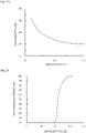
- Figs. 4A and 4B illustrate examples of test data used for setting the allowable number of rotations.
- the test data illustrated in Figs. 4A and 4B is test data obtained through the shaft diameter enlargement performed on a test shaft of the same material and the same shape as the shaft workpiece W.
- the test data illustrated in Fig. 4A illustrates a relationship between the compressive force and the number of rotations obtained by changing the number of rotations of the test shaft necessary for enlarging an intermediate portion of the test shaft to a predetermined outer diameter by changing the compressive force applied to the intermediate portion of the test shaft.
- the test data illustrated in Fig. 4B illustrates a crack occurrence probability, in relation to the number of rotations corresponding to each compressive force, at a boundary of the test shaft obtained by subjecting a plurality of test shafts to the shaft diameter enlargement with each of set compressive forces.
- the crack occurrence probability at the boundary is 0% when the number of rotations is 40 or less, the crack occurrence probability is increased as the number of rotations is increased beyond 40, and when the number of rotations is 70 or more, the crack occurrence probability is 100%. It can be said that as the number of rotations is increased, the number of times of repeated application of the alternate load is increased, and as the number of times of repeated application of the alternate load is increased, the material becomes fatigued, and hence the crack occurrence probability is increased.
- the allowable number of rotations can be set to the number of rotations at which the crack occurrence probability is equal to or lower than a threshold value, and the threshold value of the crack occurrence probability can be set in consideration of yield and the like to, for example, 0%. Therefore, according to the test data of Fig.
- the allowable number of rotations can be set to 40, which is the upper limit of the number of rotations at which the crack occurrence probability is 0%, and preferably, can be set to the number of rotations with a margin, set in consideration of variation in material characteristics of the shaft workpiece, from the number of rotations of 40 corresponding to the upper limit at which the crack occurrence probability is 0%, and the allowable number of rotations can be set to, for example, 32 (with a margin of 20%).
- the test data to be used for setting the allowable number of rotations is preferably test data obtained by subjecting a test shaft of the same material and the same shape as the shaft workpiece W to the shaft diameter enlargement performed at the same bending angle as the shaft workpiece W.
- Figs. 5A and 5B illustrate examples of test data to be used for setting the allowable enlargement ratio.
- the test data illustrated in Figs. 5A and 5B is test data obtained through the shaft diameter enlargement performed on a test shaft of the same material and the same shape as the shaft workpiece W.
- the test data illustrated in Fig. 5A illustrates a relationship between the compressive ratio L/Lo and the enlargement ratio D/Do obtained by changing the enlargement ratio D/Do of an intermediate portion of the test shaft by changing the compression ratio L/Lo of the intermediate portion of the test shaft.
- the test data illustrated in Fig. 5B illustrates a crack occurrence probability, in relation to the enlargement ratio, at an outer periphery of the intermediate portion of the test shaft obtained by subjecting a plurality of test shafts to the shaft diameter enlargement at each of set enlargement ratios.
- the crack occurrence probability at the outer periphery is 0% when the enlargement ratio is 1.8 or less, the crack occurrence probability is increased as the enlargement ratio is increased beyond 1.8, and when the enlargement ratio is 3.0 or more, the crack occurrence probability is 100%. It can be said that as the enlargement ratio is increased, a probability of exceeding the malleability limit of the material is increased, and hence the crack occurrence probability is increased.
- the allowable enlargement ratio can be set to an enlargement ratio at which the crack occurrence probability is equal to or lower than a threshold value, and the threshold value of the crack occurrence probability can be set in consideration of yield and the like to, for example, 0%. Therefore, according to the test data of Fig.
- the allowable enlargement ratio can be set to 1.8, which is the upper limit of the enlargement ratio at which the crack occurrence probability is 0%, and preferably, can be set to an enlargement ratio with a margin, set in consideration of variation in material characteristics of the shaft workpiece, from the enlargement ratio of 40 corresponding to the upper limit at which the crack occurrence probability is 0%, and the allowable enlargement ratio can be set to, for example, 1.6 (with a margin of 10%).
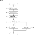
- Fig. 6 illustrates the steps performed by the controller 13 in the shaft diameter enlargement of the shaft workpiece W according to an embodiment of the invention.
- processing conditions are input to the operating section 11, and the controller 13 stores the input processing conditions (step S1).
- the input processing conditions include the compressive force, the rotational speed, the bending angle ⁇ , an enlargement terminating condition, and the allowable number of rotations N.
- the compressive force and the rotational speed can be appropriately set, and for example, from the viewpoint of shortening a cycle time, can be set to the maximum values that can be output by the compressing section 4 and the rotating section 6.
- the enlargement terminating condition is a condition for detecting that the intermediate portion Wa of the shaft workpiece W has been enlarged to the predetermined outer diameter, and when the shaft diameter enlargement apparatus 1 includes the axial displacement detector 9 configured to detect the amount of displacement of the holder 2, the amount of displacement of the holder 2 (the amount of compression of the intermediate portion Wa) caused after start of increase of the compressive force is set. Alternatively, when the shaft diameter enlargement apparatus 1 includes the radial displacement detector 10 configured to detect the amount of change in the outer diameter of the intermediate portion Wa, the amount of change in the outer diameter from the outer diameter of the intermediate portion Wa before the enlargement is set.
- the amount of displacement of the holder 2 or the amount of change in the outer diameter of the intermediate portion Wa is set in relation to the allowable enlargement ratio.
- a shaft workpiece W in which an enlargement ratio D/Do, Do being an outer diameter Do of an intermediate portion Wa before the enlargement and D being an outer diameter of the intermediate portion Wa required after the enlargement, is equal to or smaller than the allowable enlargement ratio is selected, from a plurality of shaft workpieces having different outer diameters Do, in accordance with the outer diameter D required after the enlargement.
- the amount of change in the outer diameter of the intermediate portion Wa corresponds to a difference between the outer diameter Do of the intermediate portion Wa of the selected shaft workpiece W before the enlargement and the outer diameter D required after the enlargement.
- the volume of the intermediate portion Wa does not change through the shaft diameter enlargement.
- An axial length L of the intermediate portion Wa after the enlargement is obtained based on an axial length Lo of the intermediate portion Wa before the enlargement and the enlargement ratio D/Do which is equal to or smaller than the allowable enlargement ratio.
- the amount of displacement of the holder 2 corresponds to a difference between the axial length Lo of the intermediate portion Wa before the enlargement and the axial length L after the enlargement.
- the allowable number of rotations N corresponds to the allowable number of rotations of the selected shaft workpiece W.
- the bending angle ⁇ can be set to the same bending angle employed in the shaft diameter enlargement performed, on a test shaft of the same material and the same shape as the selected shaft workpiece W, for obtaining the test data to be used for setting the allowable number of rotations N.
- step S2 when a processing start instruction is input to the operating section 11, the controller 13 controls the compressing section 4, the bending section 5 and the rotating section 6 in accordance with the processing conditions input in step S1 to perform the shaft diameter enlargement on the shaft workpiece W as illustrated in Figs. 3A to 3D (step S2).
- step S3 the controller 13 terminates the shaft diameter enlargement on the shaft workpiece W (step S3).
- the controller 13 obtains the number of rotations of the shaft workpiece W detected by the rotation detector 7, that is, a number of rotations n required for enlarging the intermediate portion Wa to the predetermined outer diameter D, and determines, based on the obtained number of rotations n, whether the shaft workpiece W is acceptable (step S4). In this determination for acceptability, the controller 13 uses the allowable number of rotations N input in step S1, so as to determine the shaft workpiece as acceptable when n ⁇ N (step S5) and as unacceptable when n > N (step S6).
- a case where the number of rotations n exceeds the allowable number of rotations N is, for example, a case where the shaft workpiece W is specifically hard due to variation in the material characteristics of the shaft workpiece.
- n > N a crack is expected to occur at the boundary of the shaft workpiece W at a probability corresponding to the number of rotations n on the interpolation curve of the test data illustrated in Fig. 4B . Therefore, the controller 13 determines that the shaft workpiece is unacceptable when n > N.
- the determination result is, for example, displayed in the display section 12 under control of the controller 13 to inform an operator.
- the determination can be made immediately after completing the shaft diameter enlargement, and the time and cost required for checking the presence of a crack can be reduced.
- the amount of displacement of the holder 2 or the amount of change in the outer diameter of the intermediate portion Wa used as the enlargement terminating condition is set in relation to the allowable enlargement ratio, and hence the occurrence of a crack at the outer periphery of the shaft workpiece W can be also suppressed.
- the time and cost required for checking the presence of a crack can be further reduced.
- Fig. 7 illustrates the steps performed by the controller 13 in the shaft diameter enlargement of the shaft workpiece W according to another embodiment of the invention.
- the shaft diameter enlargement apparatus 1 includes the axial displacement detector 9 configured to detect the amount of displacement of the holder 2, and the radial displacement detector 10 configured to detect the amount of change in the outer diameter of the intermediate portion Wa of the shaft workpiece W.
- the enlargement terminating condition is set based on the amount of displacement of the holder 2.
- the radial displacement detector 10 detects the amount of change in the outer diameter of the intermediate portion Wa at which the shaft diameter enlargement is to be terminated.
- the processing conditions are input to the operating section 11, and the controller 13 stores the input processing conditions (step S11).
- the controller 13 controls, in accordance with the processing conditions input in step S11, the compressing section 4, the bending section 5 and the rotating section 6 to perform the shaft diameter enlargement on the shaft workpiece W as illustrated in Figs. 3A to 3D (step S12).
- the controller 13 terminates the shaft diameter enlargement of the shaft workpiece W (step S13).
- the controller 13 obtains the amount of change in the outer diameter of the intermediate portion Wa detected by the radial displacement detector 10, and obtains an enlargement ratio of the intermediate portion Wa at which the shaft diameter enlargement is to be terminated (step S14).
- the enlargement ratio of the intermediate portion Wa can be obtained as (D 0 + ⁇ D)/D 0 using the outer diameter Do before the enlargement of the intermediate portion Wa and the amount ⁇ D of change in the outer diameter of the intermediate portion Wa detected by the radial displacement detector 10.
- the controller 13 determines acceptability of the shaft workpiece W based on the enlargement ratio (D 0 + ⁇ D)/D 0 obtained in step S14 (step S15). In this determination for acceptability, the controller 13 uses the allowable enlargement ratio D/Do input in step S11 to determine the shaft workpiece as acceptable when (D 0 + ⁇ D)/D 0 ⁇ D/Do (step S16) and as unacceptable when (D 0 + ⁇ D)/D 0 > D/Do (step S17).
- a case where the enlargement ratio (D 0 + ⁇ D)/D 0 exceeds the allowable enlargement ratio D/Do is, for example, a case where the axial length Lo of the intermediate portion Wa of the shaft workpiece W to be enlarged is specifically large due to dimensional error of the shaft workpiece and hence the amount ⁇ D of change in the outer diameter after the enlargement is specifically large.
- the amount of displacement of the holder 2 is constant, as the axial length Lo before the enlargement is larger, the amount ⁇ D of change in the outer diameter of the intermediate portion Wa is larger.
- the controller 13 determines the shaft workpiece as unacceptable when (D 0 + ⁇ D)/D 0 > D/Do.
- the determination result is, for example, displayed in the display section 12 under control of the controller 13 to inform an operator.
- the determination can be made immediately after completing the shaft diameter enlargement, and the time and cost required for checking the presence of a crack can be reduced.
- the determination for the acceptability on the occurrence of a crack at the outer periphery based on the enlargement ratio and the allowable enlargement ratio of the intermediate portion Wa illustrated in Fig. 7 can be performed in combination with the determination for the acceptability on the occurrence of a crack at the boundary based on the number of rotations and the allowable number of rotations of the shaft workpiece W illustrated in Fig. 6 .
Landscapes
- Engineering & Computer Science (AREA)
- Mechanical Engineering (AREA)
- Forging (AREA)
- Investigating Strength Of Materials By Application Of Mechanical Stress (AREA)
Description
- The present invention relates to a method for setting conditions for a shaft diameter enlargement, and a method and an apparatus for the shaft diameter enlargement.
- A shaft diameter enlargement is a method for forming a large diameter portion on a portion of a shaft workpiece. With the shaft diameter enlargement method, an intermediate portion of a shaft workpiece is enlarged by rotating the shaft workpiece while applying a compressive force and a bending angle to the intermediate portion of the shaft workpiece.
- In general, in a shaft diameter enlargement apparatus used in the shaft diameter enlargement, a shaft workpiece is held by a pair of holders disposed at a distance from each other in an axial direction of the shaft workpiece, the distance between the pair of holders is reduced to apply a compressive force to an intermediate portion of the shaft workpiece, one of the holders is inclined against the other of the holders to apply a bending angle to the intermediate portion, and in this state, the pair of holders are rotated to rotate the shaft workpiece, and thus, the intermediate portion of the shaft workpiece is enlarged. The process for enlarging the intermediate portion of the shaft workpiece is ended when the distance between the pair of holders is reduced to a prescribed distance (see, for example,
JP2008-212937A JP2008-212936A - Document
JP 2016 055292 A claims - The shaft diameter enlargement can sometimes cause a crack at a boundary between the enlarged intermediate portion and a shaft portion other than the intermediate portion or at an outer periphery of the enlarged intermediate portion. A crack can be detected by, for example, visual inspection, magnetic particle inspection, eddy current inspection or the like, but it requires time and cost to check all mass-produced shaft products.
- Illustrative aspects of the present invention provide a method for setting conditions for a shaft diameter enlargement, a shaft diameter enlargement method and a shaft diameter enlargement apparatus in which time and cost necessary for checking presence of a crack can be reduced.
- According to a first aspect of the present invention, a method for setting conditions for a shaft diameter enlargement is provided. In the shaft diameter enlargement, an axially intermediate portion of a shaft workpiece is enlarged in a radial direction by rotating the shaft workpiece about an axis of the shaft workpiece with axial compressive force being applied to the intermediate portion and with a bending angle being applied to the intermediate portion. The method includes setting an allowable number of rotations based on test data. The test data is obtained by performing the shaft diameter enlargement on test shafts, each of the test shafts being made of a same material and having a same shape as the shaft workpiece. The test data is indicative of a relationship between, for each of the test shafts, a number of rotations of the test shaft required for enlarging an axially intermediate portion of the test shaft to a predetermined outer diameter and a crack occurrence probability at a boundary between the intermediate portion of the test shaft and a shaft portion of the test shaft other than the intermediate portion. The allowable number of rotations is set such that the crack occurrence probability at the boundary is equal to or lower than a threshold value. The method further includes setting that a number of rotations of the shaft workpiece in enlarging the intermediate portion of the shaft workpiece to have the predetermined diameter by performing the shaft diameter enlargement on the shaft workpiece be equal to or less than the allowable number of rotations.
- According to a second aspect of the present invention, another method for setting conditions for the shaft diameter enlargement is provided. In the shaft diameter enlargement, an axially intermediate portion of a shaft workpiece is enlarged in a radial direction by rotating the shaft workpiece about an axis of the shaft workpiece with axial compressive force being applied to the intermediate portion and with a bending angle being applied to the intermediate portion. The method includes setting an allowable enlargement ratio based on test data. The test data is obtained by performing the shaft diameter enlargement on test shafts, each of the test shafts having a same material and a same shape as the shaft workpiece. The test data is indicative of a relationship between, for each of the test shafts, an enlargement ratio and a crack occurrence probability at an outer periphery of an axially intermediate portion of the test shaft, the enlargement ratio being a ratio of an outer diameter of the intermediate portion of the test shaft after the shaft diameter enlargement to an outer diameter of the test shaft before the shaft diameter enlargement. The allowable enlargement ratio is set such that the crack occurrence probability at the outer periphery is equal to or lower than a threshold value. The method further includes setting that an enlargement ratio of the intermediate portion of the shaft workpiece in enlarging the intermediate portion of the shaft workpiece to have a predetermined outer diameter by performing the shaft diameter enlargement on the shaft workpiece be equal to or smaller than the allowable enlargement ratio.
- According to a third aspect of the present invention, a shaft diameter enlargement method for enlarging an axially intermediate portion a shaft workpiece in a radial direction is provided. The method for setting conditions according to the first aspect is used. The shaft diameter enlargement method includes rotating the shaft workpiece about an axis of the shaft workpiece with axial compressive force being applied to the intermediate portion and with a bending angle being applied to the intermediate portion, and determining whether the shaft workpiece is acceptable based on a number of rotations of the shaft workpiece required for enlarging the intermediate portion of the shaft workpiece to have a predetermined outer diameter, the acceptable shaft workpiece being defined as no occurrence of a crack at a boundary between the enlarged intermediate portion and a shaft portion other than the intermediate portion or at an outer periphery of the enlarged intermediate portion.
- According to a fourth aspect of the present invention, another shaft diameter enlargement method for enlarging an axially intermediate portion a shaft workpiece in a radial direction is provided. The method for setting conditions according to the second aspect is used. The shaft diameter enlargement method includes rotating the shaft workpiece about an axis of the shaft workpiece with an axial compressive force being applied to the intermediate portion and with a bending angle applied to the intermediate portion, and determining whether the shaft workpiece is acceptable based on an enlargement ratio, the enlargement ratio being a ratio of an outer diameter of the intermediate portion of the shaft workpiece after being enlarged to an outer diameter of the intermediate portion before being enlarged, the acceptable shaft workpiece being defined as no occurrence of a crack at a boundary between the enlarged intermediate portion and a shaft portion other than the intermediate portion or at an outer periphery of the enlarged intermediate portion.
- According to a fifth aspect of the present invention, a shaft diameter enlargement apparatus includes a pair of holders disposed at a distance from each other in an axial direction of a shaft workpiece and configured to hold the shaft workpiece, a compressing section configured to apply an axial compressive force to an intermediate portion of the shaft workpiece disposed between the pair of holders by reducing the distance between the pair of holders, a bending section configured to apply a bending angle to the intermediate portion of the shaft workpiece by inclining one of the pair of holders with respect to the other holder, a rotating section configured to rotate the pair of holders and the shaft workpiece about an axis of the shaft workpiece, a rotation detector configured to detect a number of rotations of the shaft workpiece, and a controller configured to control the compressing section, the bending section, and the rotating section, so as to enlarge the intermediate portion of the shaft workpiece to have a predetermined outer diameter by rotating the shaft workpiece about the axis of the shaft workpiece with the axial compressive force being applied to the intermediate portion of the shaft workpiece and with the bending angle being applied to the intermediate portion of the shaft workpiece. The controller is configured to determine whether the shaft workpiece is acceptable based on the number of rotations required for enlarging the intermediate portion of the shaft workpiece to have the predetermined outer diameter, the acceptable shaft workpiece being defined as no occurrence of a crack at a boundary between the enlarged intermediate portion and a shaft portion other than the intermediate portion or at an outer periphery of the enlarged intermediate portion. The number of rotations is an allowable number of rotations set such that a crack occurrence probability at the boundary is equal to or lower than a threshold value.
- According to a sixth aspect of the present invention, a shaft diameter enlargement apparatus includes a pair of holders disposed at a distance from each other in an axial direction of a shaft workpiece and configured to hold the shaft workpiece, a compressing section configured to apply an axial compressive force to an intermediate portion of the shaft workpiece disposed between the pair of holders by reducing the distance between the pair of holders, a bending section configured to apply a bending angle to the intermediate portion of the shaft workpiece by inclining one of the pair of holders with respect to the other holder, a rotating section configured rotate the pair of holders and the shaft workpiece about an axis of the shaft workpiece, an axial displacement detector configured to detect an amount of change in the distance between the pair of holders, a radial displacement detector configured to detect an amount of change in an outer diameter of the intermediate portion of the shaft workpiece, and a controller configured to control the compressing section, the bending section, and the rotating section, so as to enlarge the intermediate portion of the shaft workpiece by rotating the shaft workpiece about the axis of the shaft workpiece and reducing, by a predetermined amount, the distance between the pair of holders with the axial compressive force being applied to the intermediate portion of the shaft workpiece and with the bending angle applied to the intermediate portion of the shaft workpiece. The controller is configured to obtain, based on the amount of the change in the outer diameter of the intermediate portion of the shaft workpiece, an enlargement ratio by using the radial displacement detector and to determine whether the shaft workpiece is acceptable based on the obtained enlargement ratio, the enlargement ratio being a ratio of the outer diameter of the intermediate portion of the shaft workpiece after being enlarged to the outer diameter before being enlarged, the acceptable shaft workpiece being defined as no occurrence of a crack at a boundary between the enlarged intermediate portion and a shaft portion other than the intermediate portion or at an outer periphery of the enlarged intermediate portion. The enlargement ratio is an allowable enlargement ratio set such that a crack occurrence probability at the outer periphery is equal to or lower than a threshold value
- Preferred embodiments are defined in the appended dependent claims.
-
- [
Fig. 1 ]
Fig. 1 is a block diagram illustrating a shaft diameter enlargement apparatus according to an embodiment of the present invention. - [
Fig. 2 ]
Fig. 2 is a block diagram illustrating a modification of the shaft diameter enlargement apparatus ofFig. 1 . - [
Fig. 3A ]
Fig. 3A is a schematic diagram illustrating a shaft diameter enlargement method using the shaft diameter enlargement apparatus. - [
Fig. 3B ]
Fig. 3B is another schematic diagram illustrating the shaft diameter enlargement method. - [
Fig. 3C ]
Fig. 3C is another schematic diagram illustrating the shaft diameter enlargement method. - [
Fig. 3D ]
Fig. 3D is another schematic diagram illustrating the shaft diameter enlargement method. - [
Fig. 4A ]
Fig. 4A is a graph illustrating an example of test data indicative of a relationship between a compressive force and a number of rotations with test shafts. - [
Fig. 4B ]
Fig. 4B is a graph illustrating an example of test data indicative of a relationship between the number of rotations and a crack occurrence probability with the test shafts. - [
Fig. 5A ]
Fig. 5A is a graph illustrating an example of test data indicative of a relationship between a compression ratio and an enlargement ratio with test shafts. - [
Fig. 5B ]
Fig. 5B is a graph illustrating an example of test data indicative of a relationship between the enlargement ratio and the crack occurrence probability with the test shafts. - [
Fig. 6 ]
Fig. 6 is a flowchart illustrating steps performed by a controller of the shaft diameter enlargement apparatus according to an embodiment of the present invention. - [
Fig. 7 ]
Fig. 7 is a flowchart illustrating steps performed by the controller of the shaft diameter enlargement apparatus according to another embodiment of the present invention. -
Fig. 1 illustrates a shaft diameter enlargement apparatus according to an embodiment of the present invention. - The shaft
diameter enlargement apparatus 1 ofFig. 1 includes a pair ofholders compressing section 4, abending section 5, arotating section 6, arotation detector 7 and acontrol panel 8. - The
holder 2 is configured to be fitted on an axial end of the shaft workpiece W, and theholder 3 is configured to be fitted on the other axial end of the shaft workpiece W, so that the shaft workpiece W can be held by the pair ofholders holders holders holder 2 is movable along the reference line A, i.e., movable along the axial direction of the shaft workpiece W, and theother holder 3 is movable along a direction intersecting the reference line A. - The
compressing section 4 includes, for example, a fluid pressure cylinder or the like, and moves theholder 2 along the reference line A to reduce a distance between the pair ofholders holders holders - The
bending section 5 includes, for example, a fluid pressure cylinder or the like, and moves theholder 3 in the direction crossing the reference line A to incline theholder 3 against theholder 2 disposed on the reference line A. As theholder 3 is inclined against theholder 2, a bending angle θ is applied to the intermediate portion Wa of the shaft workpiece W. - The
rotating section 6 includes, for example, an electric motor or the like, and rotates theholder 3 about a central axis of theholder 3. As theholder 3 is rotated, the shaft workpiece W whose one end is fit in theholder 3 is also rotated about its axis, and theholder 2 in which the other end of the shaft workpiece W is fit is also rotated. - The
rotation detector 7 includes, for example, a rotary encoder or the like, and is configured to detect the number of rotations of theholder 3 as the number of rotations of the shaft workpiece W. Therotation detector 7 may detect the number of rotations of theholder 2 instead of that of theholder 3, or may detect the number of rotations of the shaft workpiece W. - The
control panel 8 has hardware keys such as switches, includes anoperating section 11 to be used for inputting processing conditions and the like, and a display device such as a liquid crystal display (LCD), and includes adisplay section 12 displaying an operatio screen and the like and acontroller 13. - The
controller 13 is, for example, a computer such as a programmable logic controller (PLC). Thecontroller 13 includes one or more processors, and a memory device such as a read only memory (ROM) or a random access memory (RAM) for storing a program to be executed by the one or more processors and the processing conditions input through the operatingsection 11. Thecontroller 13 is configured to control, when the one or more processors executes the program, thecompressing section 4, thebending section 5 and therotating section 6. - Under the control of the
controller 13, the shaft workpiece W is rotated about its axis by therotating section 6 with the axial compressive force being applied to the intermediate portion Wa of the shaft workpiece W by thecompressing section 4, and with the bending angle θ being applied to the intermediate portion Wa of the shaft workpiece W by thebending section 5. In this manner, the intermediate portion Wa of the shaft workpiece W is compressed in the axial direction and enlarged in a radial direction. - The number of rotations detected by the
rotation detector 7 is input to thecontroller 13. Thecompressing section 4 includes a sensor configured to detect the compressive force. Thebending section 5 includes a sensor configured to detect the bending angle θ based on, for example, an amount of displacement of theholder 3. Therotating section 6 includes a sensor configured to detect a rotational speed of theholder 3. The compressive force, the bending angle θ and the rotational speed detected by these sensors are also input to thecontroller 13. The rotational speed may be calculated by thecontroller 13 based on the number of rotations detected by therotation detector 7. - The shaft
diameter enlargement apparatus 1 further includes anaxial displacement detector 9. Theaxial displacement detector 9 includes, for example, a linear encoder or the like, and is configured to detect an amount of displacement of theholder 2 moved by thecompressing section 4. - The amount of displacement of the
holder 2 detected by theaxial displacement detector 9 is input to thecontroller 13. Thecontroller 13 detects an amount of compression of the intermediate portion Wa of the shaft workpiece W (i.e., an amount of reduction of the length along the axial direction of the intermediate portion Wa) based on the amount of displacement of theholder 2 caused after starting increase of the compressive force, and detects, based on the amount of compression, that the intermediate portion Wa has been enlarged to a predetermined outer diameter. - The shaft
diameter enlargement apparatus 1 may include aradial displacement detector 10 configured to detect an amount of change in the outer diameter of the intermediate portion Wa of the shaft workpiece W as illustrated inFig. 2 , so that thecontroller 13 may detect that the intermediate portion Wa has been enlarged to the predetermined outer diameter based on the amount of change, from the outer diameter before the enlargement, in the outer diameter of the intermediate portion Wa detected by theradial displacement detector 10. - Now, a shaft diameter enlargement method using the shaft
diameter enlargement apparatus 1 will be described with reference toFigs. 3A to 3E. - First, as illustrated in
Fig. 3A , the shaft workpiece W is held by the pair ofholders - Next, as illustrated in
Fig. 3B , theholder 2 is moved by the compressing section 4 (seeFig. 1 ) along the reference line A, and thus, axial compressive force is applied to the intermediate portion Wa of the shaft workpiece W. In addition, theholder 3 is inclined by the bending section 5 (seeFig. 1 ) with respect to theholder 2, and thus, a bending angle θ is applied to the intermediate portion Wa. The bending angle θ is set to an angle at which the bent of the shaft workpiece W can be within deformation of elastic limit of the shaft workpiece W, and is typically about 2°to 4°although varied depending on the elastic limit of a material of the shaft workpiece W. With the compressive force and the bending angle θ thus being applied to the intermediate portion Wa of the shaft workpiece W, theholder 3 is rotated by the rotating section 6 (seeFig. 1 ), so as to rotate the shaft workpiece W about its axis. - As illustrated in
Fig. 3C , in accordance with the compression, bent and rotation of the intermediate portion Wa of the shaft workpiece W, alternate load in the radial direction is applied to each portion in the circumferential direction of the intermediate portion Wa, and when the alternate load is repeatedly applied, the intermediate portion Wa is gradually enlarged in the radial direction. Specifically, through the compression and the bent of the intermediate portion Wa, the material positioned inside of the bent swells out through plastic flow. Then, as the shaft workpiece W is rotated, the swell of the material positioned inside of the bent of the intermediate portion Wa through the plastic flow grows over the whole circumference, and thus, the intermediate portion Wa is gradually enlarged in the radial direction. - As illustrated in
Fig. 3D , when the controller 13 (seeFig. 1 ) detects, based on the amount of compression of the intermediate portion Wa of the shaft workpiece W, or based on the amount of change in the outer diameter of the intermediate portion Wa, that the intermediate portion Wa has been enlarged to the predetermined outer diameter, the compression of the intermediate portion Wa is stopped. Then, theholder 3 is disposed again along the reference line A to unbend the intermediate portion Wa of the shaft workpiece W, and thus, the enlarged thickness of the intermediate portion Wa is made uniform over the entire circumference. Through this process, the shaft diameter enlargement of the shaft workpiece W is completed, and the rotation of the shaft workpiece W is stopped. - Occurrence of a crack at a boundary between the intermediate portion Wa of the shaft workpiece W thus subjected to the shaft diameter enlargement and a shaft portion excluding the intermediate portion Wa (a part fit in the
holder 2 or 3) is derived from fatigue of the material due to the repeated application of the alternate load, and is in association with the number of rotations of the shaft workpiece W required for enlarging the intermediate portion Wa to the predetermined outer diameter. Therefore, as a processing condition, an allowable number of rotations is set on the number of rotations of the shaft workpiece W required for enlarging the intermediate portion Wa to the predetermined outer diameter. - Besides, the occurrence of a crack at an outer periphery of the intermediate portion Wa of the shaft workpiece W subjected to the shaft diameter enlargement is derived from the enlargement of the intermediate portion Wa beyond the limit of malleability of the material, and is in association with the enlargement ratio D/Do of the intermediate portion Wa. Therefore, as a processing condition, an allowable enlargement ratio is set on the enlargement ratio D/Do of the intermediate portion Wa.
-
Figs. 4A and 4B illustrate examples of test data used for setting the allowable number of rotations. - The test data illustrated in
Figs. 4A and 4B is test data obtained through the shaft diameter enlargement performed on a test shaft of the same material and the same shape as the shaft workpiece W. The test data illustrated inFig. 4A illustrates a relationship between the compressive force and the number of rotations obtained by changing the number of rotations of the test shaft necessary for enlarging an intermediate portion of the test shaft to a predetermined outer diameter by changing the compressive force applied to the intermediate portion of the test shaft. Besides, the test data illustrated inFig. 4B illustrates a crack occurrence probability, in relation to the number of rotations corresponding to each compressive force, at a boundary of the test shaft obtained by subjecting a plurality of test shafts to the shaft diameter enlargement with each of set compressive forces. - According to an interpolation curve of the test data of
Fig. 4B , the crack occurrence probability at the boundary is 0% when the number of rotations is 40 or less, the crack occurrence probability is increased as the number of rotations is increased beyond 40, and when the number of rotations is 70 or more, the crack occurrence probability is 100%. It can be said that as the number of rotations is increased, the number of times of repeated application of the alternate load is increased, and as the number of times of repeated application of the alternate load is increased, the material becomes fatigued, and hence the crack occurrence probability is increased. - The allowable number of rotations can be set to the number of rotations at which the crack occurrence probability is equal to or lower than a threshold value, and the threshold value of the crack occurrence probability can be set in consideration of yield and the like to, for example, 0%. Therefore, according to the test data of
Fig. 4B , the allowable number of rotations can be set to 40, which is the upper limit of the number of rotations at which the crack occurrence probability is 0%, and preferably, can be set to the number of rotations with a margin, set in consideration of variation in material characteristics of the shaft workpiece, from the number of rotations of 40 corresponding to the upper limit at which the crack occurrence probability is 0%, and the allowable number of rotations can be set to, for example, 32 (with a margin of 20%). - When the bending angle θ to be applied to the intermediate portion Wa of the shaft workpiece W is relatively small, the fatigue of the material caused by each application of the alternate load is relatively small, and when the bending angle θ to be applied to the intermediate portion Wa of the shaft workpiece W is relatively large, the fatigue of the material caused by each application of the alternate load is relatively large. In other words, the bending angle θ to be applied to the intermediate portion Wa is also involved in the crack occurrence at the boundary of the shaft workpiece W. Therefore, the test data to be used for setting the allowable number of rotations is preferably test data obtained by subjecting a test shaft of the same material and the same shape as the shaft workpiece W to the shaft diameter enlargement performed at the same bending angle as the shaft workpiece W.
-
Figs. 5A and 5B illustrate examples of test data to be used for setting the allowable enlargement ratio. - The test data illustrated in
Figs. 5A and 5B is test data obtained through the shaft diameter enlargement performed on a test shaft of the same material and the same shape as the shaft workpiece W. The test data illustrated inFig. 5A illustrates a relationship between the compressive ratio L/Lo and the enlargement ratio D/Do obtained by changing the enlargement ratio D/Do of an intermediate portion of the test shaft by changing the compression ratio L/Lo of the intermediate portion of the test shaft. Besides, the test data illustrated inFig. 5B illustrates a crack occurrence probability, in relation to the enlargement ratio, at an outer periphery of the intermediate portion of the test shaft obtained by subjecting a plurality of test shafts to the shaft diameter enlargement at each of set enlargement ratios. - According to an interpolation curve of the test data of
Fig. 5B , the crack occurrence probability at the outer periphery is 0% when the enlargement ratio is 1.8 or less, the crack occurrence probability is increased as the enlargement ratio is increased beyond 1.8, and when the enlargement ratio is 3.0 or more, the crack occurrence probability is 100%. It can be said that as the enlargement ratio is increased, a probability of exceeding the malleability limit of the material is increased, and hence the crack occurrence probability is increased. - The allowable enlargement ratio can be set to an enlargement ratio at which the crack occurrence probability is equal to or lower than a threshold value, and the threshold value of the crack occurrence probability can be set in consideration of yield and the like to, for example, 0%. Therefore, according to the test data of
Fig. 5B , the allowable enlargement ratio can be set to 1.8, which is the upper limit of the enlargement ratio at which the crack occurrence probability is 0%, and preferably, can be set to an enlargement ratio with a margin, set in consideration of variation in material characteristics of the shaft workpiece, from the enlargement ratio of 40 corresponding to the upper limit at which the crack occurrence probability is 0%, and the allowable enlargement ratio can be set to, for example, 1.6 (with a margin of 10%). -
Fig. 6 illustrates the steps performed by thecontroller 13 in the shaft diameter enlargement of the shaft workpiece W according to an embodiment of the invention. - First, processing conditions are input to the
operating section 11, and thecontroller 13 stores the input processing conditions (step S1). The input processing conditions include the compressive force, the rotational speed, the bending angle θ, an enlargement terminating condition, and the allowable number of rotations N. The compressive force and the rotational speed can be appropriately set, and for example, from the viewpoint of shortening a cycle time, can be set to the maximum values that can be output by thecompressing section 4 and therotating section 6. - The enlargement terminating condition is a condition for detecting that the intermediate portion Wa of the shaft workpiece W has been enlarged to the predetermined outer diameter, and when the shaft
diameter enlargement apparatus 1 includes theaxial displacement detector 9 configured to detect the amount of displacement of theholder 2, the amount of displacement of the holder 2 (the amount of compression of the intermediate portion Wa) caused after start of increase of the compressive force is set. Alternatively, when the shaftdiameter enlargement apparatus 1 includes theradial displacement detector 10 configured to detect the amount of change in the outer diameter of the intermediate portion Wa, the amount of change in the outer diameter from the outer diameter of the intermediate portion Wa before the enlargement is set. - The amount of displacement of the
holder 2 or the amount of change in the outer diameter of the intermediate portion Wa is set in relation to the allowable enlargement ratio. First, a shaft workpiece W in which an enlargement ratio D/Do, Do being an outer diameter Do of an intermediate portion Wa before the enlargement and D being an outer diameter of the intermediate portion Wa required after the enlargement, is equal to or smaller than the allowable enlargement ratio is selected, from a plurality of shaft workpieces having different outer diameters Do, in accordance with the outer diameter D required after the enlargement. The amount of change in the outer diameter of the intermediate portion Wa corresponds to a difference between the outer diameter Do of the intermediate portion Wa of the selected shaft workpiece W before the enlargement and the outer diameter D required after the enlargement. The volume of the intermediate portion Wa does not change through the shaft diameter enlargement. An axial length L of the intermediate portion Wa after the enlargement is obtained based on an axial length Lo of the intermediate portion Wa before the enlargement and the enlargement ratio D/Do which is equal to or smaller than the allowable enlargement ratio. The amount of displacement of theholder 2 corresponds to a difference between the axial length Lo of the intermediate portion Wa before the enlargement and the axial length L after the enlargement. - The allowable number of rotations N corresponds to the allowable number of rotations of the selected shaft workpiece W. The bending angle θ can be set to the same bending angle employed in the shaft diameter enlargement performed, on a test shaft of the same material and the same shape as the selected shaft workpiece W, for obtaining the test data to be used for setting the allowable number of rotations N.
- Next, when a processing start instruction is input to the
operating section 11, thecontroller 13 controls thecompressing section 4, thebending section 5 and therotating section 6 in accordance with the processing conditions input in step S1 to perform the shaft diameter enlargement on the shaft workpiece W as illustrated inFigs. 3A to 3D (step S2). When the amount of displacement of theholder 2 detected by theaxial displacement detector 9 or the amount of change in the outer diameter of the intermediate portion Wa detected by the radialdisplacement detecting part 10 reaches the enlargement terminating condition, thecontroller 13 terminates the shaft diameter enlargement on the shaft workpiece W (step S3). - Next, the
controller 13 obtains the number of rotations of the shaft workpiece W detected by therotation detector 7, that is, a number of rotations n required for enlarging the intermediate portion Wa to the predetermined outer diameter D, and determines, based on the obtained number of rotations n, whether the shaft workpiece W is acceptable (step S4). In this determination for acceptability, thecontroller 13 uses the allowable number of rotations N input in step S1, so as to determine the shaft workpiece as acceptable when n ≦ N (step S5) and as unacceptable when n > N (step S6). - A case where the number of rotations n exceeds the allowable number of rotations N is, for example, a case where the shaft workpiece W is specifically hard due to variation in the material characteristics of the shaft workpiece. When n > N, a crack is expected to occur at the boundary of the shaft workpiece W at a probability corresponding to the number of rotations n on the interpolation curve of the test data illustrated in
Fig. 4B . Therefore, thecontroller 13 determines that the shaft workpiece is unacceptable when n > N. The determination result is, for example, displayed in thedisplay section 12 under control of thecontroller 13 to inform an operator. - When the acceptability on the crack occurrence at the boundary of the shaft workpiece W is thus determined based on the number of rotations n required for enlarging the intermediate portion Wa of the shaft workpiece W to the predetermined outer diameter D, the determination can be made immediately after completing the shaft diameter enlargement, and the time and cost required for checking the presence of a crack can be reduced.
- Furthermore, in this exemplified case, the amount of displacement of the
holder 2 or the amount of change in the outer diameter of the intermediate portion Wa used as the enlargement terminating condition is set in relation to the allowable enlargement ratio, and hence the occurrence of a crack at the outer periphery of the shaft workpiece W can be also suppressed. Thus, the time and cost required for checking the presence of a crack can be further reduced. -
Fig. 7 illustrates the steps performed by thecontroller 13 in the shaft diameter enlargement of the shaft workpiece W according to another embodiment of the invention. - As illustrated in
Fig. 7 , the compressive force, the rotational speed, the bending angle θ, the enlargement terminating condition and the allowable enlargement ratio D/Do are input as the processing conditions, and thecontroller 13 determines the acceptability by using the input allowable enlargement ratio D/Do. The shaftdiameter enlargement apparatus 1 includes theaxial displacement detector 9 configured to detect the amount of displacement of theholder 2, and theradial displacement detector 10 configured to detect the amount of change in the outer diameter of the intermediate portion Wa of the shaft workpiece W. The enlargement terminating condition is set based on the amount of displacement of theholder 2. Theradial displacement detector 10 detects the amount of change in the outer diameter of the intermediate portion Wa at which the shaft diameter enlargement is to be terminated. - First, the processing conditions are input to the
operating section 11, and thecontroller 13 stores the input processing conditions (step S11). Next, when a processing start instruction is input to theoperating section 11, thecontroller 13 controls, in accordance with the processing conditions input in step S11, thecompressing section 4, thebending section 5 and therotating section 6 to perform the shaft diameter enlargement on the shaft workpiece W as illustrated inFigs. 3A to 3D (step S12). When the amount of displacement of theholder 2 detected by theaxial displacement detector 9 reaches the enlargement terminating condition, thecontroller 13 terminates the shaft diameter enlargement of the shaft workpiece W (step S13). - Next, the
controller 13 obtains the amount of change in the outer diameter of the intermediate portion Wa detected by theradial displacement detector 10, and obtains an enlargement ratio of the intermediate portion Wa at which the shaft diameter enlargement is to be terminated (step S14). The enlargement ratio of the intermediate portion Wa can be obtained as (D0+ΔD)/D0 using the outer diameter Do before the enlargement of the intermediate portion Wa and the amount ΔD of change in the outer diameter of the intermediate portion Wa detected by theradial displacement detector 10. - Then, the
controller 13 determines acceptability of the shaft workpiece W based on the enlargement ratio (D0+ΔD)/D0 obtained in step S14 (step S15). In this determination for acceptability, thecontroller 13 uses the allowable enlargement ratio D/Do input in step S11 to determine the shaft workpiece as acceptable when (D0+ΔD)/D0 ≦ D/Do (step S16) and as unacceptable when (D0+ΔD)/D0 > D/Do (step S17). - A case where the enlargement ratio (D0+ΔD)/D0 exceeds the allowable enlargement ratio D/Do is, for example, a case where the axial length Lo of the intermediate portion Wa of the shaft workpiece W to be enlarged is specifically large due to dimensional error of the shaft workpiece and hence the amount ΔD of change in the outer diameter after the enlargement is specifically large. Assuming that the amount of displacement of the
holder 2 is constant, as the axial length Lo before the enlargement is larger, the amount ΔD of change in the outer diameter of the intermediate portion Wa is larger. When (D0+ΔD)/D0 > D/Do, a crack is expected to occur at the outer periphery of the shaft workpiece W at a probability corresponding to the enlargement ratio (D0+ΔD)/D0 on the interpolation curve of the test data illustrated inFig. 5B . Therefore, thecontroller 13 determines the shaft workpiece as unacceptable when (D0+ΔD)/D0 > D/Do. The determination result is, for example, displayed in thedisplay section 12 under control of thecontroller 13 to inform an operator. - When the acceptability on the crack occurrence at the outer periphery of the shaft workpiece W is thus determined based on the enlargement ratio of the intermediate portion Wa of the shaft workpiece W, the determination can be made immediately after completing the shaft diameter enlargement, and the time and cost required for checking the presence of a crack can be reduced.
- The determination for the acceptability on the occurrence of a crack at the outer periphery based on the enlargement ratio and the allowable enlargement ratio of the intermediate portion Wa illustrated in
Fig. 7 can be performed in combination with the determination for the acceptability on the occurrence of a crack at the boundary based on the number of rotations and the allowable number of rotations of the shaft workpiece W illustrated inFig. 6 .
Claims (10)
- A method for setting conditions for a shaft diameter enlargement in which an axially intermediate portion (Wa) of a shaft workpiece (W) is enlarged in a radial direction by rotating the shaft workpiece (W) about an axis of the shaft workpiece (W) with axial compressive force being applied to the intermediate portion (Wa) and with a bending angle being applied to the intermediate portion (Wa), the method being characterized in that it comprises:setting an allowable number of rotations (N) based on test data, wherein the test data is obtained by performing the shaft diameter enlargement on test shafts, each of the test shafts being made of a same material and having a same shape as the shaft workpiece (W), wherein the test data is indicative of a relationship between, for each of the test shafts, a number of rotations of the test shaft required for enlarging an axially intermediate portion of the test shaft to a predetermined outer diameter and a crack occurrence probability at a boundary between the intermediate portion of the test shaft and a shaft portion of the test shaft other than the intermediate portion, and wherein the allowable number of rotations (N) is set such that the crack occurrence probability at the boundary is equal to or lower than a threshold value; andsetting that a number of rotations (n) of the shaft workpiece (W) in enlarging the intermediate portion (Wa) of the shaft workpiece (W) to have the predetermined diameter by performing the shaft diameter enlargement on the shaft workpiece (W) be equal to or less than the allowable number of rotations (N).
- The method according to claim 1, wherein the test data is obtained by performing the shaft diameter enlargement on the test shafts with the same bending angle as in the shaft diameter enlargement to be performed on the shaft workpiece (W).
- A method for setting conditions for a shaft diameter enlargement in which an axially intermediate portion (Wa) of a shaft workpiece (W) is enlarged in a radial direction by rotating the shaft workpiece (W) about an axis of the shaft workpiece (W) with axial compressive force being applied to the intermediate portion (Wa) and with a bending angle being applied to the intermediate portion (Wa), the method being charcaterized in that it comprises:setting an allowable enlargement ratio based on test data, wherein the test data is obtained by performing the shaft diameter enlargement on test shafts, each of the test shafts having a same material and a same shape as the shaft workpiece (W), wherein the test data is indicative of a relationship between, for each of the test shafts, an enlargement ratio and a crack occurrence probability at an outer periphery of an axially intermediate portion (Wa) of the test shaft, the enlargement ratio being a ratio of an outer diameter of the intermediate portion of the test shaft after the shaft diameter enlargement to an outer diameter of the test shaft before the shaft diameter enlargement, and wherein the allowable enlargement ratio is set such that the crack occurrence probability at the outer periphery is equal to or lower than a threshold value; andsetting that an enlargement ratio (D/DO) of the intermediate portion (Wa) of the shaft workpiece (W) in enlarging the intermediate portion (Wa) of the shaft workpiece (W) to have a predetermined outer diameter by performing the shaft diameter enlargement on the shaft workpiece (W) be equal to or smaller than the allowable enlargement ratio.
- A shaft diameter enlargement method for enlarging an axially intermediate portion (Wa) of a shaft workpiece (W) in a radial direction by using the method for setting conditions defined in claim 1 or 2, the shaft diameter enlargement method comprising:rotating the shaft workpiece (W) about an axis of the shaft workpiece (W) with axial compressive force being applied to the intermediate portion (Wa) and with a bending angle being applied to the intermediate portion (Wa); anddetermining whether the shaft workpiece (W) is acceptable based on a number of rotations (n) of the shaft workpiece (W) required for enlarging the intermediate portion (Wa) of the shaft workpiece (W) to have a predetermined outer diameter, the acceptable shaft workpiece being defined as no occurrence of a crack at a boundary between the enlarged intermediate portion (Wa) and a shaft portion other than the intermediate portion (Wa) or at an outer periphery of the enlarged intermediate portion (Wa).
- The shaft diameter enlargement method according to claim 4, further comprising:setting an allowable enlargement ratio based on the test data, wherein the test data is obtained by performing the shaft diameter enlargement on the test shafts, wherein the test data is indicative of a relationship between, for each of the test shafts, an enlargement ratio and a crack occurrence probability at an outer periphery of an axially intermediate portion of the test shaft, the enlargement ratio being a ratio of an outer diameter of the intermediate portion of the test shaft after the shaft diameter enlargement to an outer diameter of the test shaft before the shaft diameter enlargement, and wherein the allowable enlargement ratio is set such that the crack occurrence probability at the outer periphery is equal to or lower than a threshold value; andsetting that an enlargement ratio (D/DO) of the intermediate portion (Wa) of the shaft workpiece (W) in enlarging the intermediate portion (Wa) of the shaft workpiece (W) to have the predetermined outer diameter be equal to or smaller than the allowable enlargement ratio.
- A shaft diameter enlargement method for enlarging an axially intermediate portion (Wa) of a shaft workpiece (W) in a radial direction by using the method for setting conditions defined in claim 3, the shaft diameter enlargement method comprising:rotating the shaft workpiece (W) about an axis of the shaft workpiece (W) with an axial compressive force being applied to the intermediate portion (Wa) and with a bending angle applied to the intermediate portion (Wa); anddetermining whether the shaft workpiece (W) is acceptable based on an enlargement ratio (D/D0), the enlargement ratio (D/DO) being a ratio of an outer diameter (D) of the intermediate portion (Wa) of the shaft workpiece (W) after being enlarged to an outer diameter (D0) of the intermediate portion (Wa) before being enlarged, the acceptable shaft workpiece being defined as no occurrence of a crack at a boundary between the enlarged intermediate portion (Wa) and a shaft portion other than the intermediate portion (Wa) or at an outer periphery of the enlarged intermediate portion (Wa).
- The shaft diameter enlargement method according to claim 6, further comprising:setting an allowable number of rotations (N) based on test data, wherein the test data is obtained by performing a shaft diameter enlargement on test shafts, each of the test shafts being made of a same material and having a same shape as the shaft workpiece (W), wherein the test data is indicative of a relationship between, for each of the test shafts, a number of rotations (n) of the test shaft required for enlarging an axially intermediate portion of the test shaft to a predetermined outer diameter and a crack occurrence probability at a boundary between the intermediate portion of the test shaft and a shaft portion of the test shaft other than the intermediate portion, and wherein the allowable number of rotations (N) is set such that the crack occurrence probability at the boundary is equal to or lower than a threshold value,wherein the shaft workpiece (W) is determined as being acceptable when the number of rotations (n) of the shaft workpiece (W) is equal to or less than the allowable number of rotations (N), and the shaft workpiece (W) is determined as being unacceptable when the number of rotations (n) of the shaft workpiece (W) exceeds the allowable number of rotations (N).
- The shaft diameter enlargement method according to claim 7, wherein the test data is obtained by performing the shaft diameter enlargement on the test shafts with the same bending angle as in the shaft diameter enlargement to be performed on the shaft workpiece (W).
- A shaft diameter enlargement apparatus, comprising:a pair of holders (2) disposed at a distance from each other in an axial direction of a shaft workpiece (W) and configured to hold the shaft workpiece (W);a compressing section (4) configured to apply an axial compressive force to an intermediate portion (Wa) of the shaft workpiece (W) disposed between the pair of holders (2) by reducing the distance between the pair of holders (2);a bending section (5) configured to apply a bending angle to the intermediate portion (Wa) of the shaft workpiece (W) by inclining one of the pair of holders (2) with respect to the other holder;a rotating section (6) configured to rotate the pair of holders (2) and the shaft workpiece (W)about an axis of the shaft workpiece (W);a rotation detector (7) configured to detect a number of rotations (n) of the shaft workpiece (W); anda controller (13) configured to control the compressing section (4), the bending section (5), and the rotating section (6), so as to enlarge the intermediate portion (Wa) of the shaft workpiece (W) to have a predetermined outer diameter by rotating the shaft workpiece (W) about the axis of the shaft workpiece (W) with the axial compressive force being applied to the intermediate portion (Wa) of the shaft workpiece (W) and with the bending angle being applied to the intermediate portion (Wa) of the shaft workpiece (W),characterized in that: the controller (13) is configured to determine whether the shaft workpiece (W) is acceptable based on the number of rotations (n) required for enlarging the intermediate portion (Wa) of the shaft workpiece (W) to have the predetermined outer diameter, the acceptable shaft workpiece being defined as no occurrence of a crack at a boundary between the enlarged intermediate portion (Wa) and a shaft portion other than the intermediate portion (Wa) or at an outer periphery of the enlarged intermediate portion (Wa), andwherein said number of rotations (n) is an allowable number of rotations (N) set such that a crack occurrence probability at the boundary is equal to or lower than a threshold value.
- A shaft diameter enlargement apparatus, comprising:a pair of holders (2) disposed at a distance from each other in an axial direction of a shaft workpiece (W) and configured to hold the shaft workpiece (W);a compressing section (4) configured to apply an axial compressive force to an intermediate portion (Wa) of the shaft workpiece (W) disposed between the pair of holders (2) by reducing the distance between the pair of holders (2);a bending section (5) configured to apply a bending angle to the intermediate portion (Wa) of the shaft workpiece (W) by inclining one of the pair of holders (2) with respect to the other holder;a rotating section (6) configured rotate the pair of holders (2) and the shaft workpiece (W) about an axis of the shaft workpiece (W);an axial displacement detector (9) configured to detect an amount of change in the distance between the pair of holders (2);a radial displacement detector (10) configured to detect an amount of change in an outer diameter of the intermediate portion (Wa) of the shaft workpiece (W); anda controller (13) configured to control the compressing section (4), the bending section (5), and the rotating section (6), so as to enlarge the intermediate portion (Wa) of the shaft workpiece (W) by rotating the shaft workpiece (W) about the axis of the shaft workpiece (W) and reducing, by a predetermined amount, the distance between the pair of holders (2) with the axial compressive force being applied to the intermediate portion (Wa) of the shaft workpiece (W) and with the bending angle applied to the intermediate portion (Wa) of the shaft workpiece (W),characterized in that: the controller (13) is configured to obtain, based on the amount of the change in the outer diameter of the intermediate portion (Wa) of the shaft workpiece (W), an enlargement ratio (D/DO) by using the radial displacement detector (10) and to determine whether the shaft workpiece (W) is acceptable based on the obtained enlargement ratio (D/D0), the enlargement ratio being a ratio of the outer diameter (D) of the intermediate portion (Wa) of the shaft workpiece (W) after being enlarged to the outer diameter (D0) before being enlarged, the acceptable shaft workpiece being defined as no occurrence of a crack at a boundary between the enlarged intermediate portion (Wa) and a shaft portion other than the intermediate portion (Wa) or at an outer periphery of the enlarged intermediate portion (Wa), andwherein said enlargement ratio (D/DO) is an allowable enlargement ratio set such that a crack occurrence probability at the outer periphery is equal to or lower than a threshold value.
Applications Claiming Priority (2)
| Application Number | Priority Date | Filing Date | Title |
|---|---|---|---|
| JP2017212187A JP2019084539A (en) | 2017-11-01 | 2017-11-01 | Processing condition setting method of shaft thickening processing, shaft thickening processing method and shaft thickening processing apparatus |
| PCT/JP2018/040459 WO2019088153A1 (en) | 2017-11-01 | 2018-10-31 | Shaft diameter enlargement condition setting method, shaft diameter enlargement method and shaft diameter enlargement apparatus |
Publications (2)
| Publication Number | Publication Date |
|---|---|
| EP3703882A1 EP3703882A1 (en) | 2020-09-09 |
| EP3703882B1 true EP3703882B1 (en) | 2022-12-28 |
Family
ID=64332364
Family Applications (1)
| Application Number | Title | Priority Date | Filing Date |
|---|---|---|---|
| EP18804427.5A Active EP3703882B1 (en) | 2017-11-01 | 2018-10-31 | Shaft diameter enlargement condition setting method, shaft diameter enlargement method and shaft diameter enlargement apparatus |
Country Status (6)
| Country | Link |
|---|---|
| US (1) | US11565307B2 (en) |
| EP (1) | EP3703882B1 (en) |
| JP (6) | JP2019084539A (en) |
| CN (1) | CN111315506B (en) |
| MX (1) | MX2020004550A (en) |
| WO (1) | WO2019088153A1 (en) |
Family Cites Families (16)
| Publication number | Priority date | Publication date | Assignee | Title |
|---|---|---|---|---|
| JP3809129B2 (en) * | 2002-04-25 | 2006-08-16 | 株式会社いうら | Method and apparatus for shaft enlargement processing of metal shaft |
| JP2007169684A (en) * | 2005-12-20 | 2007-07-05 | Iura Co Ltd | Pre-treatment for improving axial thickening workability |
| JP4832136B2 (en) | 2006-03-29 | 2011-12-07 | 株式会社いうら | Shaft enlargement processing method |
| JP2007268602A (en) * | 2006-03-31 | 2007-10-18 | Komatsu Ltd | Shaft enlargement molding apparatus and shaft enlargement molding method |
| JP4927599B2 (en) | 2007-02-28 | 2012-05-09 | 株式会社いうら | Axial hypertrophy processing machine and processing method thereof |
| JP4927600B2 (en) | 2007-02-28 | 2012-05-09 | 株式会社いうら | Shaft enlargement processing method |
| CN101185952A (en) * | 2007-11-05 | 2008-05-28 | 机械科学研究总院先进制造技术研究中心 | Two-sided roll milling forming method and two-sided roll milling forming equipment |
| JP5000465B2 (en) * | 2007-11-27 | 2012-08-15 | 高周波熱錬株式会社 | Axial enlargement processing apparatus and method |
| JP5302592B2 (en) | 2008-07-31 | 2013-10-02 | 高周波熱錬株式会社 | Workpiece enlargement processing method |
| KR101246705B1 (en) * | 2011-04-25 | 2013-04-04 | 주식회사 프론텍 | Nipple manufacturing method |
| JP5349563B2 (en) * | 2011-10-24 | 2013-11-20 | 株式会社いうら | Shaft enlargement processing method |
| JP5993581B2 (en) | 2012-02-21 | 2016-09-14 | 高周波熱錬株式会社 | Monitoring system for shaft enlargement processing machine |
| JP6076301B2 (en) * | 2014-09-05 | 2017-02-08 | ジヤトコ株式会社 | Shaft enlargement molding apparatus and shaft enlargement molding method |
| JP6463953B2 (en) * | 2014-11-20 | 2019-02-06 | 高周波熱錬株式会社 | Shaft enlargement processing machine and shaft enlargement processing method |
| JP6465214B2 (en) * | 2015-08-24 | 2019-02-06 | 新日鐵住金株式会社 | Rail axle |
| JP2017144471A (en) * | 2016-02-17 | 2017-08-24 | 高周波熱錬株式会社 | Shaft enlargement processing method |
-
2017
- 2017-11-01 JP JP2017212187A patent/JP2019084539A/en not_active Withdrawn
-
2018
- 2018-10-31 US US16/753,069 patent/US11565307B2/en active Active
- 2018-10-31 MX MX2020004550A patent/MX2020004550A/en unknown
- 2018-10-31 EP EP18804427.5A patent/EP3703882B1/en active Active
- 2018-10-31 WO PCT/JP2018/040459 patent/WO2019088153A1/en not_active Ceased
- 2018-10-31 CN CN201880071275.0A patent/CN111315506B/en active Active
-
2021
- 2021-09-27 JP JP2021157093A patent/JP7237123B2/en active Active
-
2023
- 2023-02-28 JP JP2023029746A patent/JP7576114B2/en active Active
-
2024
- 2024-03-06 JP JP2024033779A patent/JP7663734B2/en active Active
-
2025
- 2025-03-28 JP JP2025056250A patent/JP7847253B2/en active Active
-
2026
- 2026-01-13 JP JP2026003538A patent/JP2026053764A/en active Pending
Also Published As
| Publication number | Publication date |
|---|---|
| CN111315506B (en) | 2022-05-10 |
| JP2024059985A (en) | 2024-05-01 |
| US11565307B2 (en) | 2023-01-31 |
| JP2019084539A (en) | 2019-06-06 |
| JP2021191593A (en) | 2021-12-16 |
| JP2023065553A (en) | 2023-05-12 |
| JP2026053764A (en) | 2026-03-25 |
| MX2020004550A (en) | 2020-08-03 |
| WO2019088153A1 (en) | 2019-05-09 |
| EP3703882A1 (en) | 2020-09-09 |
| JP2025094267A (en) | 2025-06-24 |
| JP7576114B2 (en) | 2024-10-30 |
| CN111315506A (en) | 2020-06-19 |
| JP7847253B2 (en) | 2026-04-16 |
| JP7237123B2 (en) | 2023-03-10 |
| JP7663734B2 (en) | 2025-04-16 |
| US20200290114A1 (en) | 2020-09-17 |
Similar Documents
| Publication | Publication Date | Title |
|---|---|---|
| Quigley et al. | Metal forming: an analysis of spinning processes | |
| US8620598B2 (en) | Bushing press-fitting inspection device, method, and program, and bushing press-fitting apparatus | |
| US20140305176A1 (en) | Universal roller swaging machine with tool wear monitor | |
| Ahmed et al. | Deep spinning of sheet metals | |
| JP2012073182A (en) | Method for testing material | |
| EP3182089A1 (en) | Tire testing device | |
| KR20230041625A (en) | Spring back prediction method and deformed bar bending method | |
| US11565307B2 (en) | Shaft diameter enlargement condition setting method, shaft diameter enlargement method and shaft diameter enlargement apparatus | |
| JP6282814B2 (en) | Tire testing machine | |
| JP6729210B2 (en) | Material testing machine | |
| JP4927599B2 (en) | Axial hypertrophy processing machine and processing method thereof | |
| CN105127242B (en) | A kind of axial workpiece curvature correction method | |
| JP2017144471A (en) | Shaft enlargement processing method | |
| Pirling et al. | Residual stress distribution in seamless tubes determined experimentally and by FEM | |
| CN112540012B (en) | A circumferential pure shear loading method and device for pipes | |
| Qiao et al. | Torque strength and influencing factors analysis for assembled camshaft by knurling joining | |
| JP2017006934A (en) | Tube expansion device | |
| US7100411B2 (en) | Device for reshaping and/or folding bodies of cans | |
| WO2016079997A1 (en) | Shaft diameter enlarging apparatus and shaft diameter enlarging method | |
| Kajikawa et al. | Rotary tube flaring using a conical punch with grooves for high forming limit and productivity | |
| KR101903236B1 (en) | Localized torsional severe plastic deformation method for conical tube metals | |
| KR102325840B1 (en) | A system for manufacturing pipe | |
| JPS6411865B2 (en) | ||
| JPWO2017037792A1 (en) | Cylindrical member processing method and processing apparatus | |
| JP6375766B2 (en) | Elastic body moving device and component manufacturing method |
Legal Events
| Date | Code | Title | Description |
|---|---|---|---|
| STAA | Information on the status of an ep patent application or granted ep patent |
Free format text: STATUS: UNKNOWN |
|
| STAA | Information on the status of an ep patent application or granted ep patent |
Free format text: STATUS: THE INTERNATIONAL PUBLICATION HAS BEEN MADE |
|
| PUAI | Public reference made under article 153(3) epc to a published international application that has entered the european phase |
Free format text: ORIGINAL CODE: 0009012 |
|
| STAA | Information on the status of an ep patent application or granted ep patent |
Free format text: STATUS: REQUEST FOR EXAMINATION WAS MADE |
|
| 17P | Request for examination filed |
Effective date: 20200330 |
|
| AK | Designated contracting states |
Kind code of ref document: A1 Designated state(s): AL AT BE BG CH CY CZ DE DK EE ES FI FR GB GR HR HU IE IS IT LI LT LU LV MC MK MT NL NO PL PT RO RS SE SI SK SM TR |
|
| AX | Request for extension of the european patent |
Extension state: BA ME |
|
| DAV | Request for validation of the european patent (deleted) | ||
| DAX | Request for extension of the european patent (deleted) | ||
| STAA | Information on the status of an ep patent application or granted ep patent |
Free format text: STATUS: EXAMINATION IS IN PROGRESS |
|
| 17Q | First examination report despatched |
Effective date: 20210604 |
|
| GRAP | Despatch of communication of intention to grant a patent |
Free format text: ORIGINAL CODE: EPIDOSNIGR1 |
|
| STAA | Information on the status of an ep patent application or granted ep patent |
Free format text: STATUS: GRANT OF PATENT IS INTENDED |
|
| INTG | Intention to grant announced |
Effective date: 20220712 |
|
| RAP3 | Party data changed (applicant data changed or rights of an application transferred) |
Owner name: NETUREN CO., LTD. |
|
| RIN1 | Information on inventor provided before grant (corrected) |
Inventor name: IKEDA, TAKASHI Inventor name: MORI, KAZUKI Inventor name: KUWAHARA, YOSHITAKA Inventor name: IKUTA, FUMIAKI Inventor name: OKAMOTO, MITSUHIRO |
|
| GRAS | Grant fee paid |
Free format text: ORIGINAL CODE: EPIDOSNIGR3 |
|
| GRAA | (expected) grant |
Free format text: ORIGINAL CODE: 0009210 |
|
| STAA | Information on the status of an ep patent application or granted ep patent |
Free format text: STATUS: THE PATENT HAS BEEN GRANTED |
|
| AK | Designated contracting states |
Kind code of ref document: B1 Designated state(s): AL AT BE BG CH CY CZ DE DK EE ES FI FR GB GR HR HU IE IS IT LI LT LU LV MC MK MT NL NO PL PT RO RS SE SI SK SM TR |
|
| REG | Reference to a national code |
Ref country code: GB Ref legal event code: FG4D |
|
| REG | Reference to a national code |
Ref country code: CH Ref legal event code: EP |
|
| REG | Reference to a national code |
Ref country code: DE Ref legal event code: R096 Ref document number: 602018044817 Country of ref document: DE |
|
| REG | Reference to a national code |
Ref country code: AT Ref legal event code: REF Ref document number: 1540135 Country of ref document: AT Kind code of ref document: T Effective date: 20230115 |
|
| REG | Reference to a national code |
Ref country code: IE Ref legal event code: FG4D |
|
| REG | Reference to a national code |
Ref country code: LT Ref legal event code: MG9D |
|
| PG25 | Lapsed in a contracting state [announced via postgrant information from national office to epo] |
Ref country code: SE Free format text: LAPSE BECAUSE OF FAILURE TO SUBMIT A TRANSLATION OF THE DESCRIPTION OR TO PAY THE FEE WITHIN THE PRESCRIBED TIME-LIMIT Effective date: 20221228 Ref country code: NO Free format text: LAPSE BECAUSE OF FAILURE TO SUBMIT A TRANSLATION OF THE DESCRIPTION OR TO PAY THE FEE WITHIN THE PRESCRIBED TIME-LIMIT Effective date: 20230328 Ref country code: LT Free format text: LAPSE BECAUSE OF FAILURE TO SUBMIT A TRANSLATION OF THE DESCRIPTION OR TO PAY THE FEE WITHIN THE PRESCRIBED TIME-LIMIT Effective date: 20221228 Ref country code: FI Free format text: LAPSE BECAUSE OF FAILURE TO SUBMIT A TRANSLATION OF THE DESCRIPTION OR TO PAY THE FEE WITHIN THE PRESCRIBED TIME-LIMIT Effective date: 20221228 |
|
| REG | Reference to a national code |
Ref country code: NL Ref legal event code: MP Effective date: 20221228 |
|
| REG | Reference to a national code |
Ref country code: AT Ref legal event code: MK05 Ref document number: 1540135 Country of ref document: AT Kind code of ref document: T Effective date: 20221228 |
|
| PG25 | Lapsed in a contracting state [announced via postgrant information from national office to epo] |
Ref country code: RS Free format text: LAPSE BECAUSE OF FAILURE TO SUBMIT A TRANSLATION OF THE DESCRIPTION OR TO PAY THE FEE WITHIN THE PRESCRIBED TIME-LIMIT Effective date: 20221228 Ref country code: LV Free format text: LAPSE BECAUSE OF FAILURE TO SUBMIT A TRANSLATION OF THE DESCRIPTION OR TO PAY THE FEE WITHIN THE PRESCRIBED TIME-LIMIT Effective date: 20221228 Ref country code: HR Free format text: LAPSE BECAUSE OF FAILURE TO SUBMIT A TRANSLATION OF THE DESCRIPTION OR TO PAY THE FEE WITHIN THE PRESCRIBED TIME-LIMIT Effective date: 20221228 Ref country code: GR Free format text: LAPSE BECAUSE OF FAILURE TO SUBMIT A TRANSLATION OF THE DESCRIPTION OR TO PAY THE FEE WITHIN THE PRESCRIBED TIME-LIMIT Effective date: 20230329 |
|
| PG25 | Lapsed in a contracting state [announced via postgrant information from national office to epo] |
Ref country code: NL Free format text: LAPSE BECAUSE OF FAILURE TO SUBMIT A TRANSLATION OF THE DESCRIPTION OR TO PAY THE FEE WITHIN THE PRESCRIBED TIME-LIMIT Effective date: 20221228 |
|
| PG25 | Lapsed in a contracting state [announced via postgrant information from national office to epo] |
Ref country code: SM Free format text: LAPSE BECAUSE OF FAILURE TO SUBMIT A TRANSLATION OF THE DESCRIPTION OR TO PAY THE FEE WITHIN THE PRESCRIBED TIME-LIMIT Effective date: 20221228 Ref country code: RO Free format text: LAPSE BECAUSE OF FAILURE TO SUBMIT A TRANSLATION OF THE DESCRIPTION OR TO PAY THE FEE WITHIN THE PRESCRIBED TIME-LIMIT Effective date: 20221228 Ref country code: PT Free format text: LAPSE BECAUSE OF FAILURE TO SUBMIT A TRANSLATION OF THE DESCRIPTION OR TO PAY THE FEE WITHIN THE PRESCRIBED TIME-LIMIT Effective date: 20230428 Ref country code: ES Free format text: LAPSE BECAUSE OF FAILURE TO SUBMIT A TRANSLATION OF THE DESCRIPTION OR TO PAY THE FEE WITHIN THE PRESCRIBED TIME-LIMIT Effective date: 20221228 Ref country code: EE Free format text: LAPSE BECAUSE OF FAILURE TO SUBMIT A TRANSLATION OF THE DESCRIPTION OR TO PAY THE FEE WITHIN THE PRESCRIBED TIME-LIMIT Effective date: 20221228 Ref country code: CZ Free format text: LAPSE BECAUSE OF FAILURE TO SUBMIT A TRANSLATION OF THE DESCRIPTION OR TO PAY THE FEE WITHIN THE PRESCRIBED TIME-LIMIT Effective date: 20221228 Ref country code: AT Free format text: LAPSE BECAUSE OF FAILURE TO SUBMIT A TRANSLATION OF THE DESCRIPTION OR TO PAY THE FEE WITHIN THE PRESCRIBED TIME-LIMIT Effective date: 20221228 |
|
| PG25 | Lapsed in a contracting state [announced via postgrant information from national office to epo] |
Ref country code: SK Free format text: LAPSE BECAUSE OF FAILURE TO SUBMIT A TRANSLATION OF THE DESCRIPTION OR TO PAY THE FEE WITHIN THE PRESCRIBED TIME-LIMIT Effective date: 20221228 Ref country code: PL Free format text: LAPSE BECAUSE OF FAILURE TO SUBMIT A TRANSLATION OF THE DESCRIPTION OR TO PAY THE FEE WITHIN THE PRESCRIBED TIME-LIMIT Effective date: 20221228 Ref country code: IS Free format text: LAPSE BECAUSE OF FAILURE TO SUBMIT A TRANSLATION OF THE DESCRIPTION OR TO PAY THE FEE WITHIN THE PRESCRIBED TIME-LIMIT Effective date: 20230428 Ref country code: AL Free format text: LAPSE BECAUSE OF FAILURE TO SUBMIT A TRANSLATION OF THE DESCRIPTION OR TO PAY THE FEE WITHIN THE PRESCRIBED TIME-LIMIT Effective date: 20221228 |
|
| REG | Reference to a national code |
Ref country code: DE Ref legal event code: R097 Ref document number: 602018044817 Country of ref document: DE |
|
| PG25 | Lapsed in a contracting state [announced via postgrant information from national office to epo] |
Ref country code: DK Free format text: LAPSE BECAUSE OF FAILURE TO SUBMIT A TRANSLATION OF THE DESCRIPTION OR TO PAY THE FEE WITHIN THE PRESCRIBED TIME-LIMIT Effective date: 20221228 |
|
| PLBE | No opposition filed within time limit |
Free format text: ORIGINAL CODE: 0009261 |
|
| STAA | Information on the status of an ep patent application or granted ep patent |
Free format text: STATUS: NO OPPOSITION FILED WITHIN TIME LIMIT |
|
| 26N | No opposition filed |
Effective date: 20230929 |
|
| PG25 | Lapsed in a contracting state [announced via postgrant information from national office to epo] |
Ref country code: SI Free format text: LAPSE BECAUSE OF FAILURE TO SUBMIT A TRANSLATION OF THE DESCRIPTION OR TO PAY THE FEE WITHIN THE PRESCRIBED TIME-LIMIT Effective date: 20221228 |
|
| PG25 | Lapsed in a contracting state [announced via postgrant information from national office to epo] |
Ref country code: IT Free format text: LAPSE BECAUSE OF FAILURE TO SUBMIT A TRANSLATION OF THE DESCRIPTION OR TO PAY THE FEE WITHIN THE PRESCRIBED TIME-LIMIT Effective date: 20221228 Ref country code: MC Free format text: LAPSE BECAUSE OF FAILURE TO SUBMIT A TRANSLATION OF THE DESCRIPTION OR TO PAY THE FEE WITHIN THE PRESCRIBED TIME-LIMIT Effective date: 20221228 |
|
| REG | Reference to a national code |
Ref country code: CH Ref legal event code: PL |
|
| REG | Reference to a national code |
Ref country code: BE Ref legal event code: MM Effective date: 20231031 |
|
| PG25 | Lapsed in a contracting state [announced via postgrant information from national office to epo] |
Ref country code: LU Free format text: LAPSE BECAUSE OF NON-PAYMENT OF DUE FEES Effective date: 20231031 |
|
| GBPC | Gb: european patent ceased through non-payment of renewal fee |
Effective date: 20231031 |
|
| PG25 | Lapsed in a contracting state [announced via postgrant information from national office to epo] |
Ref country code: LU Free format text: LAPSE BECAUSE OF NON-PAYMENT OF DUE FEES Effective date: 20231031 |
|
| PG25 | Lapsed in a contracting state [announced via postgrant information from national office to epo] |
Ref country code: GB Free format text: LAPSE BECAUSE OF NON-PAYMENT OF DUE FEES Effective date: 20231031 |
|
| PG25 | Lapsed in a contracting state [announced via postgrant information from national office to epo] |
Ref country code: CH Free format text: LAPSE BECAUSE OF NON-PAYMENT OF DUE FEES Effective date: 20231031 |
|
| PG25 | Lapsed in a contracting state [announced via postgrant information from national office to epo] |
Ref country code: GB Free format text: LAPSE BECAUSE OF NON-PAYMENT OF DUE FEES Effective date: 20231031 Ref country code: FR Free format text: LAPSE BECAUSE OF NON-PAYMENT OF DUE FEES Effective date: 20231031 Ref country code: CH Free format text: LAPSE BECAUSE OF NON-PAYMENT OF DUE FEES Effective date: 20231031 |
|
| PG25 | Lapsed in a contracting state [announced via postgrant information from national office to epo] |
Ref country code: BE Free format text: LAPSE BECAUSE OF NON-PAYMENT OF DUE FEES Effective date: 20231031 |
|
| PG25 | Lapsed in a contracting state [announced via postgrant information from national office to epo] |
Ref country code: IE Free format text: LAPSE BECAUSE OF NON-PAYMENT OF DUE FEES Effective date: 20231031 |
|
| PG25 | Lapsed in a contracting state [announced via postgrant information from national office to epo] |
Ref country code: IE Free format text: LAPSE BECAUSE OF NON-PAYMENT OF DUE FEES Effective date: 20231031 |
|
| PG25 | Lapsed in a contracting state [announced via postgrant information from national office to epo] |
Ref country code: BG Free format text: LAPSE BECAUSE OF FAILURE TO SUBMIT A TRANSLATION OF THE DESCRIPTION OR TO PAY THE FEE WITHIN THE PRESCRIBED TIME-LIMIT Effective date: 20221228 |
|
| PG25 | Lapsed in a contracting state [announced via postgrant information from national office to epo] |
Ref country code: BG Free format text: LAPSE BECAUSE OF FAILURE TO SUBMIT A TRANSLATION OF THE DESCRIPTION OR TO PAY THE FEE WITHIN THE PRESCRIBED TIME-LIMIT Effective date: 20221228 |
|
| PG25 | Lapsed in a contracting state [announced via postgrant information from national office to epo] |
Ref country code: CY Free format text: LAPSE BECAUSE OF FAILURE TO SUBMIT A TRANSLATION OF THE DESCRIPTION OR TO PAY THE FEE WITHIN THE PRESCRIBED TIME-LIMIT; INVALID AB INITIO Effective date: 20181031 |
|
| PG25 | Lapsed in a contracting state [announced via postgrant information from national office to epo] |
Ref country code: HU Free format text: LAPSE BECAUSE OF FAILURE TO SUBMIT A TRANSLATION OF THE DESCRIPTION OR TO PAY THE FEE WITHIN THE PRESCRIBED TIME-LIMIT; INVALID AB INITIO Effective date: 20181031 |
|
| PG25 | Lapsed in a contracting state [announced via postgrant information from national office to epo] |
Ref country code: TR Free format text: LAPSE BECAUSE OF FAILURE TO SUBMIT A TRANSLATION OF THE DESCRIPTION OR TO PAY THE FEE WITHIN THE PRESCRIBED TIME-LIMIT Effective date: 20221228 |
|
| PGFP | Annual fee paid to national office [announced via postgrant information from national office to epo] |
Ref country code: DE Payment date: 20250902 Year of fee payment: 8 |