EP3703773B1 - Öffnungsanordnung, vorrichtung zur herstellung von gereinigtem wasser mit der öffnungsanordnung und verfahren zur öffnungsreinigung einer vorrichtung zur herstellung von gereinigtem wasser - Google Patents
Öffnungsanordnung, vorrichtung zur herstellung von gereinigtem wasser mit der öffnungsanordnung und verfahren zur öffnungsreinigung einer vorrichtung zur herstellung von gereinigtem wasser Download PDFInfo
- Publication number
- EP3703773B1 EP3703773B1 EP18795977.0A EP18795977A EP3703773B1 EP 3703773 B1 EP3703773 B1 EP 3703773B1 EP 18795977 A EP18795977 A EP 18795977A EP 3703773 B1 EP3703773 B1 EP 3703773B1
- Authority
- EP
- European Patent Office
- Prior art keywords
- port
- tube
- fluid
- door
- seal
- Prior art date
- Legal status (The legal status is an assumption and is not a legal conclusion. Google has not performed a legal analysis and makes no representation as to the accuracy of the status listed.)
- Active
Links
Images





Classifications
-
- A—HUMAN NECESSITIES
- A61—MEDICAL OR VETERINARY SCIENCE; HYGIENE
- A61M—DEVICES FOR INTRODUCING MEDIA INTO, OR ONTO, THE BODY; DEVICES FOR TRANSDUCING BODY MEDIA OR FOR TAKING MEDIA FROM THE BODY; DEVICES FOR PRODUCING OR ENDING SLEEP OR STUPOR
- A61M1/00—Suction or pumping devices for medical purposes; Devices for carrying-off, for treatment of, or for carrying-over, body-liquids; Drainage systems
- A61M1/14—Dialysis systems; Artificial kidneys; Blood oxygenators ; Reciprocating systems for treatment of body fluids, e.g. single needle systems for hemofiltration or pheresis
- A61M1/16—Dialysis systems; Artificial kidneys; Blood oxygenators ; Reciprocating systems for treatment of body fluids, e.g. single needle systems for hemofiltration or pheresis with membranes
- A61M1/168—Sterilisation or cleaning before or after use
-
- A—HUMAN NECESSITIES
- A61—MEDICAL OR VETERINARY SCIENCE; HYGIENE
- A61M—DEVICES FOR INTRODUCING MEDIA INTO, OR ONTO, THE BODY; DEVICES FOR TRANSDUCING BODY MEDIA OR FOR TAKING MEDIA FROM THE BODY; DEVICES FOR PRODUCING OR ENDING SLEEP OR STUPOR
- A61M39/00—Tubes, tube connectors, tube couplings, valves, access sites or the like, specially adapted for medical use
- A61M39/10—Tube connectors; Tube couplings
- A61M39/16—Tube connectors; Tube couplings having provision for disinfection or sterilisation
-
- C—CHEMISTRY; METALLURGY
- C02—TREATMENT OF WATER, WASTE WATER, SEWAGE, OR SLUDGE
- C02F—TREATMENT OF WATER, WASTE WATER, SEWAGE, OR SLUDGE
- C02F1/00—Treatment of water, waste water, or sewage
- C02F1/68—Treatment of water, waste water, or sewage by addition of specified substances, e.g. trace elements, for ameliorating potable water
- C02F1/685—Devices for dosing the additives
- C02F1/686—Devices for dosing liquid additives
-
- A—HUMAN NECESSITIES
- A61—MEDICAL OR VETERINARY SCIENCE; HYGIENE
- A61M—DEVICES FOR INTRODUCING MEDIA INTO, OR ONTO, THE BODY; DEVICES FOR TRANSDUCING BODY MEDIA OR FOR TAKING MEDIA FROM THE BODY; DEVICES FOR PRODUCING OR ENDING SLEEP OR STUPOR
- A61M39/00—Tubes, tube connectors, tube couplings, valves, access sites or the like, specially adapted for medical use
- A61M39/10—Tube connectors; Tube couplings
- A61M2039/1038—Union screw connectors, e.g. hollow screw or sleeve having external threads
-
- A—HUMAN NECESSITIES
- A61—MEDICAL OR VETERINARY SCIENCE; HYGIENE
- A61M—DEVICES FOR INTRODUCING MEDIA INTO, OR ONTO, THE BODY; DEVICES FOR TRANSDUCING BODY MEDIA OR FOR TAKING MEDIA FROM THE BODY; DEVICES FOR PRODUCING OR ENDING SLEEP OR STUPOR
- A61M39/00—Tubes, tube connectors, tube couplings, valves, access sites or the like, specially adapted for medical use
- A61M39/10—Tube connectors; Tube couplings
- A61M2039/1083—Tube connectors; Tube couplings having a plurality of female connectors, e.g. Luer connectors
-
- A—HUMAN NECESSITIES
- A61—MEDICAL OR VETERINARY SCIENCE; HYGIENE
- A61M—DEVICES FOR INTRODUCING MEDIA INTO, OR ONTO, THE BODY; DEVICES FOR TRANSDUCING BODY MEDIA OR FOR TAKING MEDIA FROM THE BODY; DEVICES FOR PRODUCING OR ENDING SLEEP OR STUPOR
- A61M39/00—Tubes, tube connectors, tube couplings, valves, access sites or the like, specially adapted for medical use
- A61M39/10—Tube connectors; Tube couplings
- A61M2039/1088—Tube connectors; Tube couplings having a plurality of male connectors, e.g. Luer connectors
-
- A—HUMAN NECESSITIES
- A61—MEDICAL OR VETERINARY SCIENCE; HYGIENE
- A61M—DEVICES FOR INTRODUCING MEDIA INTO, OR ONTO, THE BODY; DEVICES FOR TRANSDUCING BODY MEDIA OR FOR TAKING MEDIA FROM THE BODY; DEVICES FOR PRODUCING OR ENDING SLEEP OR STUPOR
- A61M2209/00—Ancillary equipment
- A61M2209/10—Equipment for cleaning
-
- C—CHEMISTRY; METALLURGY
- C02—TREATMENT OF WATER, WASTE WATER, SEWAGE, OR SLUDGE
- C02F—TREATMENT OF WATER, WASTE WATER, SEWAGE, OR SLUDGE
- C02F2303/00—Specific treatment goals
- C02F2303/14—Maintenance of water treatment installations
Definitions
- the present disclosure relates to the technical field of ports, and in particular to a port arrangement that regularly has to be cleaned to remove any contaminants.
- the disclosure further relates to a purified water producing apparatus comprising the port arrangement and a method for performing cleaning of the port arrangement when arranged to the purified water producing apparatus.
- PD peritoneal dialysis
- HD hemodialysis
- Such dialysis treatments require dialysis fluids that typically have been provided ready to use in sealed, sterilized containers.
- PD treatment requires between 8-20 litres of dialysis fluid per day, 7 days a week, 365 days a year for each patient.
- compounding of dialysis fluid at the point of care e.g. at the patient's home, has been implemented.
- Concentrates in liquid or dry form are then mixed with water to produce dialysis fluid at the point of care.
- the concentrates have to be provided to the point of care, but with a much smaller amount than the ready to use dialysis fluids.
- the concentrates are generally highly concentrated, 10-40x compared to ready to use fluids.
- a water purification apparatus is used to purify water accessible at the point of use, for example tap water.
- the water purification apparatus is connected to the tap water source and outputs purified water through a product port.
- a detachable fluid line connects the product port with the dialysis machine, e.g. a cycler or a HD machine, and provides purified water to be used e.g. for mixing with concentrates.
- the fluid circuits of the water purification apparatus has to be cleaned and disinfected periodically, to kill any bacteria and remove endotoxins.
- the port When manually attaching the line set to the port of the purified water producing apparatus, the port may become contaminated by bacteria from the user's hands.
- the disclosure relates to a port arrangement comprising a fluid module.
- the fluid module incorporates a first port arranged to receive a first connector, wherein the first port comprises a first tube and a first interior wall concentric with the first tube.
- the first interior wall provides a first circumferential space around the first tube.
- the first port further comprises a first seat extending from the first interior wall to form a front end of the first port.
- the fluid module further incorporates a second port arranged to receive a second connector, wherein the second port comprises a second tube and a second interior wall concentric with the second tube.
- the second interior wall provides a second circumferential space around the second tube.
- the second port further comprises a second seat extending from the second interior wall to form a front end of the second port.
- the fluid module further incorporates a bypass channel connecting the first circumferential space and the circumferential second space.
- the port arrangement further comprises a door comprising a first seal and a second seal arranged to an inner wall of the door. The door is arranged to be positioned in a closed position against the fluid module, wherein the first seal and the second seal are positioned to the inner wall such that in the closed position the first seal abut against the first seat and the second seal abut against the second seat to thereby seal the first circumferential space and the second circumferential space.
- the port arrangement makes it possible to perform a port cleaning that cleans not only the flow channels of the ports, but also the outer sides of the ports, thus an outer side of the first port and an outer side of the second port.
- the port arrangement enables both the ports to be cleaned in the same run. There is no need for cleaning the outsides of the ports by hand.
- the bypass channel resides within the fluid module, which enables efficient automatic cleaning of the ports, both inside and outside the connectors of the ports and any connector threads.
- the bypass channel connect to the first circumferential space at an inner bottom of the circumferential space, and the bypass channel connect to the second circumferential space at an inner bottom of the circumferential space.
- the bypass channel can be provided such that it connects the lower parts of the mentioned circumferential spaces. Thereby it is made sure that a cleaning solution flow across the entire outer sides of the tubes that are exposed to contaminants.
- the first seal is spaced from an end face of the first tube
- the second seal is spaced from an end face of the second tube. It is here more in detail described that, when the door is closed against the fluid module, the seals are distanced from the end faces of the tubes, such that a cleaning fluid may flow between the provided spaces outside the tubes and the interior of the tubes.
- the first port is arranged to receive the first connector at the front end of the first port, and to be connected to a product line at a back end of the first port.
- the second port is arranged to receive the second connector at the front end of the second port, and to be connected to a drain line at a back end of the second port.
- the first port may be used to connect a product line to a first connector, and to pass purified water from the product line to the first connector
- the second port may be used to connect a second connector to a drain line, and to pass drain fluid from the second connector to the drain line.
- the first port and the second port are designed as conical fittings of Luer type.
- the ports may include standard Luer type connectors that have been modified such that their outer sides can be cleaned during a port cleaning.
- the Luer type may be provided with locking thread.
- the second tube has a threaded outer side.
- the second port may thus incorporate a female conical fitting of Luer type.
- the first interior wall is threaded.
- the first port may thus incorporate a male conical fitting of Luer type.
- the bypass channel includes a main bore, a first circumferential gap around the first tube connecting to the first circumferential space, a second circumferential gap around the second tube connecting to the second space, and where the main bore connects the first circumferential gap and the second circumferential gap.
- the bypass channel is made up of several circumferential gaps that allow cleaning fluid to flow across the external sides of the tubes during cleaning.
- the bypass channel includes a third circumferential gap connecting to the second space and to the main bore. Thereby cleaning fluid is allowed to flow in a larger space that promotes a total cleaning.
- the port arrangement comprises a sensor arrangement configured to detect whether the door is in the closed position or not, and to generate a door position signal indicating the position of the door. Thereby it will be known when the seals are closing the spaces around the ports against the outside such that a port cleaning can be performed.
- the port arrangement comprises a spring-loaded latch assembly for locking the door to the fluid module. Thereby the door can be held closed to the fluid module during cleaning.
- the door further comprises a spring arrangement with a spring arranged between a spring seat of the door and the second seal.
- the second seal is being biased by the spring against an incision of an inner wall of the door with a predetermined spring force, the second seal being movable a distance ⁇ d against the spring seat by overcoming the spring force.
- the first seal and/or the second seal is arranged with an irregular surface to promote distribution of fluid.
- the disclosure relates to a purified water producing apparatus comprising a casing, a fluid circuit enclosed inside the casing and arranged to produce a flow of purified water from a source of water and to transport used fluid to a drain, and a port arrangement as described herein.
- the port arrangement is arranged to the casing such that the door, the front end of the first port and the front end of the second port are accessible from the outside of the water producing apparatus to allow fluid connection of the first connector and the second connector, and the first port and the second port are fluidly connected to the fluid circuit at respective back ends of the ports.
- the purified water producing apparatus is provided with a port arrangement that allows thorough cleaning of the ports. Thereby any bacteria of the ports may be mitigated, and the purity level of the purified water flowing through the first port may be maintained.
- the water producing apparatus comprises a control unit arranged to receive a door position signal indicating a position of the door.
- the water producing apparatus is further arranged to control a flow of cleaning fluid to the port arrangement based on the position of the door. For example, if someone accidently opens the door, the flow of cleaning fluid to the port arrangement will be stopped.
- the cleaning fluid may be purified water, heated purified water, purified water comprising a cleaning agent, or heated purified water comprising a cleaning agent.
- the water producing apparatus is arranged to direct cleaning fluid to the back end of the first port upon the door position signal indicates that the door is in a closed position.
- the cleaning fluid then enters the first tube and flows into the first space of the first port, thereafter via the bypass channel to the second space and into the second tube, where after the cleaning fluid leaves the second port via the back end of the second port and is further transported to a drain via the fluid circuit.
- the door is closed, cleaning fluid is allowed to flow through the port arrangement such that a cleaning of the ports can be performed.
- the fluid circuit comprises a heating device arranged to heat the cleaning fluid to a temperature meeting a cleaning criterion for the first port and the second port.
- the cleaning fluid may be heated such that a disinfection of the ports may be performed.
- the disclosure relates to a method for performing port cleaning of a water producing apparatus.
- the method comprising producing a cleaning fluid with the fluid circuit, passing the cleaning fluid through the first port via the first tube to the first circumferential space, from the first circumferential space via the bypass channel to the second circumferential space, and thereafter to the second tube and passing the cleaning fluid from the second tube to the drain.
- the method comprises passing the cleaning fluid during a certain time period meeting a cleaning criterion for the first port and the second port.
- the time period may be set beforehand, or determined during performance of the method based on the composition of the cleaning fluid and/or the temperature of the cleaning fluid.
- the method comprises receiving a signal indicating that the door is closed, before performing the passing step.
- the door has to be properly closed before the port cleaning is performed.
- the producing comprises producing a heated cleaning fluid.
- a heat disinfection of the ports may be performed by using the heated cleaning fluid for the port cleaning.
- the disclosure relates to a computer program comprising instructions which, when the program is executed by a control unit, cause the control unit and a thereto associated water producing apparatus to carry out the method as described herein.
- a computer-readable medium comprising instructions which, when executed by a control unit, cause the control unit and a thereto associated water producing apparatus to carry out the method.
- the cleaning fluid may be purified water, heated purified water, purified water with a cleaning agent or heated purified water with a cleaning agent.
- the cleaning agent may be an bacterial growth inhibiting agent, e.g. a physiologically safe acid, such as citric acid, citrate, lactic acid, acetic acid, hydrochlorid acid, a combination or a derivative thereof.
- the port arrangement includes a door and a fluid module including the ports.
- the port arrangement may be implemented to various apparatuses that are capable of providing a flow of cleaning fluid, but will in the following be exemplified as implemented to an apparatus capable of producing purified water.
- a water purification apparatus 100 is illustrated.
- the water purification apparatus 100 is provided with a casing 101 enclosing a fluid circuit of the water purification apparatus 100.
- a port arrangement 1 is arranged to the casing 101 for connection of connectors of a fluid line set (not shown) to the fluid circuit.
- Fig. 2 schematically illustrates main components of the water purification apparatus 100.
- the water purification apparatus 100 comprises an inlet port 102, a fluid circuit 103, the port arrangement 1, a drain port 110 and a control unit 112.
- the fluid circuit 103 is enclosed inside the casing 101 and is arranged to produce a flow of purified water from a source of water 200 connected via the inlet port 102, and to transport used fluid to a drain 202 via the drain port 110.
- the inlet port 102 is here connected to the source of water 200 being a water tap with a connecting line 201.
- the fluid circuit 103 comprises a pre-filter unit 104, a Reverse Osmosis Unit (RO Unit) 105 and a post-treatment unit 106, all fitted to a product line 108.
- RO Unit Reverse Osmosis Unit
- the product line 108 is connected to the inlet port 102 at one end, and to a first port 3 of the port arrangement 1 at the other end. It should be understood that the product line 108 is here conceptually described as one line, but could include several lines interconnected by the units etc. described as fitted to the product line 108.
- the pre-filter unit 104 is arranged to receive (unfiltered) water from the water tap, and is arranged to produce filtered water.
- the pre-filter unit 104 may include a particle filter and a bed of activated carbon.
- the RO unit 105 is arranged downstream the pre-filter unit 104 to receive the filtered water from the post-treatment unit 106.
- the RO unit 105 comprises a semipermeable membrane, and outputs permeate water.
- the post-treatment unit 106 is arranged downstream the RO unit 105 and is arranged to receive the permeate water from the RO unit 105.
- the post-treatment unit 106 further treats the permeate water and produces purified water.
- the post-treatment unit may include a polisher such as an Electrodeionization device (EDI device).
- EDI device Electrodeionization device
- a pump P is arranged upstream the RO unit 105 to provide a pressurized flow of water to the RO unit 105.
- a heating device 111 is arranged downstream the RO unit 105, but upstream the post-treatment unit 106, to heat the permeate water to a certain temperature between 70oC and 95oC.
- a valve device 107 is arranged at the product line 108 to regulate the flow in the product line 108, e.g. downstream the post-treatment unit 106. Alternatively, the valve device 107 may be arranged to a recirculation line (not shown) between a point downstream the heating device 111 but upstream the post-treatment unit 106, and a point upstream the RO unit 105.
- the pump P, the heating device 111 and the valve device 107 are arranged to be controlled by a control unit 112 of the water purification apparatus 100.
- the control unit 112 is arranged to control the pump P, the heating device 111 and the valve device 107, by sending respective signals to the same.
- the control unit 112 is arranged to control the pump to pump water with a certain flow rate, to control the heating device 111 to heat permeate water to a certain temperature, and to control the valve device 107 to stop or start a flow of fluid in the product line 108 upstream the post-treatment unit 106.
- the heating device 111 is further arranged to heat the purified water to a temperature meeting a cleaning criterion, e.g.
- the temperature of the purified water may be measured by a temperature sensor (not shown) arranged to the product line 108 downstream the heating device 111.
- the sensed temperature is sent to the control unit 112 whereupon the control unit 112 controls the heating device 111 based on the measured temperature such that the temperature meets the cleaning criterion.
- the cleaning criterion may include temperature and/or time duration for the cleaning.
- the fluid circuit 103 further includes a drain line 109 connected between a second port 5 of the port arrangement 1 and the drain port 110.
- the drain port 110 outputs drain water, e.g. used dialysis fluid or used cleaning fluid, via the second port 5 to the drain 202.
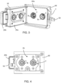
- Fig. 3 illustrates an isolated front view of the port arrangement 1.
- the port arrangement 1 comprises a fluid module 2 and a door 20.
- the fluid module 2 is made of a heat resistant material that does not release toxic substances.
- the fluid module 2 is made of polypropylene.
- the door 20 comprises an integrated first body part 20a and second body part 20b.
- the second body part 20b is a smaller extension of the first body part 20a.
- the first body part 20a comprises a first seal 21 and a second seal 22.
- the door 20 is attached to the fluid module 2 with a hinge 24 ( Fig. 15 ), and can be closed against the fluid module 2 into a closed position.
- the port arrangement 1 further comprises a port casing 60 or "port house” holding and partly enclosing the fluid module 2, and provides an attachment for the fluid module 2 to the casing 101 ( Fig. 1 ).
- the port arrangement 1 further comprises a sensor arrangement 50, e.g. including a Hall-sensor, connected to the port casing 60 or fluid module 2, which is configured to sense the proximity of a magnet (not shown) positioned in the door 20, or more precisely in the first body part 20a.
- the sensor arrangement 50 is configured to detect whether the door 20 is in the closed position or not, and to generate a door position signal indicating the position of the door 20. The door position signal thus indicates whether the door 20 is closed or not.
- the sensor arrangement 50 is arranged to send the door position signal to the control unit 112.
- the control unit 112 is arranged to control the valve unit 107 to open the flow in the product line 108 to the first port 3. If the signal indicates that the door 20 is open, the control unit 112 is arranged to control the valve unit 107 to close the flow in the product line 108 to the first port 3.
- the water producing apparatus 100 is arranged to control the flow of cleaning fluid, e.g. purified water, to the port arrangement 1 based on the position of the door 20.
- the fluid module 2 further comprises the first port 3 and the second port 5.
- the port casing 60 is provided with a casing wall 60a with two through-holes.
- the first port 3 and the second port 5 are aligned with the through-holes, such that a front end 3k of the first port 3 is accessible through one of the holes, and a front end 5k of the second port 5 is accessible through the other hole, and such that connectors can be connected to the respective ports through the holes.
- the first fluid port 3 is designed such that a first connector 4 ( Fig. 10 ) can be fluidly connected to the first fluid port 3 at the front end 3k. In other words, the first fluid port 3 is arranged to receive the first connector 4 at the front end 3k.
- the second fluid port 5 is designed such that a second connector 6 ( Fig. 10 ) can be fluidly connected to the second fluid port 5 at the front end 5k.
- the second fluid port 5 is arranged to receive the second connector 6 at the front end 5k.
- Parts of the first port 3 and the second port 5 are recessed into the casing wall 60a in the through-holes of the casing wall 60a.
- Fig. 4 illustrates a back view of the port arrangement 1 of Fig. 1 .
- the back of the port arrangement 1 is, when arranged to the wall of the casing 101, facing the interior of the water purification apparatus 100.
- the fluid module 2 comprises a back side 2c exhibiting a back end 3g of the first fluid port 3, and a back end 5g of the second fluid port 5.
- the first fluid port 3 is designed to be fluidly connected to the product line 108 ( Fig 2 ) at the back end 3g.
- the second fluid port 5 is designed to be fluidly connected to the drain line 109 ( Fig. 2 ) at the back end 5g.
- the port arrangement 1 is arranged to the casing 101 such that the door 20, the front end 3k of the first port 3 and the front end 5k of the second port 5 are accessible from the outside of the water producing apparatus 100 to allow fluid connection of the first connector 4 and the second connector 6. Then the first port 3 and the second port 5 are fluidly connected to the fluid circuit 103 at respective back ends 3g, 5g of the ports 3, 5.
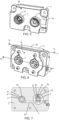
- Fig. 5 illustrates the fluid module 2 in isolation from a front view.
- the fluid module 1 comprises a body 2a with front side 2b.
- An outer circumferential wall 11 of the first port 3 projects perpendicularly from the front side 2b with a distance d1.
- An outer circumferential wall 12 of the second port 5 projects perpendicularly from the front side 2b with a distance d2.
- Fig. 6 illustrates the fluid module 2 from a back view.
- the body 2a comprises a back side 2c, positioned on the opposite side of the body 2a with regards to the front side 2b.
- the body 2a is here made up of two body pieces for ease of construction, but may be made in one piece, or more than two pieces.
- Fig. 7 illustrates a cross-section of the fluid module 2 along a plane A-A of Fig. 6 .
- the first port 3 and the second port 5 are fluidly connected with a bypass channel 7.
- the fluid module 2 is crossed by a first bore 3i with a varying first diameter and a second bore 5i with a varying second diameter.
- the first bore 3i and the second bore 5i are circular passages perpendicular to the front side 2b of the fluid module 2. These bores are thus through-holes.
- the first bore 3i accommodates a first tube 3a of the first port 3.
- the second bore 5i accommodates a second tube 5a of the second port 5.
- the first port 3 further comprises a keying means 3h in the first tube 3a arranged to hold the first tube 3a in place in a certain orientation against a socket 3j inside the first bore 3i.
- a first circumferential gap 7b is provided between the inner side of the first bore 3i and the outer side 3e of the first tube 3a.
- a second circumferential gap 7c is provided between the inner side of the second bore 5i and the outer side 5e of the second tube 5a.
- a main bore 7a of the bypass channel 7 fluidly connects the first circumferential gap 7b and the second circumferential gap 7c at a lower part of the first circumferential gap 7b and the second circumferential gap 7c.
- the bypass channel 7 is arranged to fluidly connect the first circumferential space 3c and the second circumferential space 5c at lower or lowermost parts thereof, when the fluid module 2 is in an operating position in the wall of the casing 101 (see Figs. 1-2 and 10-13 ).
- the main bore 7a is arranged parallel to the front side 2b of the fluid module 2.
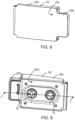
- Fig. 8 illustrates a front view of the door 20.
- the door 20 comprises a front side 20c extending over both the first part 20a and the second part 20b.
- Fig. 9 illustrates a back view of the door 20.
- the door 20 comprises an inner wall 20d, positioned on the opposite side of the door 20 of the front side 20c.
- the door 20 is provided with a first seal 21 and a second seal 22. As can be seen, the first seal 21 is hollow, and the second seal 22 is provided with a cross-like recess.
- Fig. 10 illustrates a cross-section of the fluid module 2 shown in Fig. 6 , along a plane defined by B-B.
- the bypass channel 7 has been moved towards the observer of Fig. 10 in order to make the bypass channel 7 visible in the figure.
- the fluid module 2 comprises a body 2a with a front side 2b and a back side 2c.
- the body 2a is made of several separate body parts that are assembled together.
- the body 2a comprises a first bore 3i ( Fig. 7 ) and a second bore 5i ( Fig. 7 ).
- the first port 3 comprises a first tube 3a, accommodated in the first bore 3i.
- a socket 3j is arranged aligned with the inner wall of the first bore 3i.
- the socket 3j defines a first interior wall 3b concentric with the first tube 3a.
- the first tube 3a is arranged inside the socket 3j.
- the first interior wall 3b provides a first circumferential space 3c around the first tube 3a.
- a first connector 4 has been connected to the first port 3.
- the first connector 4 is a female connector including a tube with a threaded outer side, for example a female conical fitting of Luer type.
- the first circumferential space 3c has such size that it can accommodate the threaded tube of the female connector.
- the first interior wall 3b has a diameter greater to an outer diameter of the first connector 4.
- the first interior wall 3b is correspondingly threaded.
- the first tube 3a and the first interior wall 3b makes up, or provides, a male connector of Luer type, for example a male conical fitting of Luer type.
- the conical fittings herein may have a 6% taper.
- the threads of the threaded tube of the female connector 4 engage with the threads of the first interior wall 3b to create a fluid tight connection.
- the first tube 3a extends in the first bore 3i to the back end 3g of the first port 3 and to the back side 2c of the fluid module where the first tube 3a is connected with the product line 108 with a first bond 8.
- the fluid tightness of the connection may be secured with a gasket 10e between the product line 108 and the tube 3a.
- the first bond 8 includes means to secure the product line 108 to the inside of the first tube 3a.
- the first port 3 further comprises a first seat or shoulder 3d in the body 2, extending from the first interior wall 3b to form a front end of the first port 3.
- the first seat 3d is further the front end of the outer circumferential wall 11 of the first port 3.
- the first seat 3d is connected to the inner wall of the socket 3j via an outer face of the socket 3j.
- the first seat 3d thus comprises also the outer face of the socket 3j.
- the second port 5 comprises a second tube 5a, accommodated in the second circumferential bore 5i.
- the second tube 5a is thus arranged inside the bore 5i.
- the bore 5i defines a second interior wall 5b concentric with the second tube 5a.
- the second interior wall 5b provides a second circumferential space 5c around the second tube 5c.
- a second connector 6 has been connected to the second port 5.
- the second connector 6 is a male connector with a tube and an outer collar with an interior thread, for example a male conical fitting of Luer type.
- the second circumferential space 5c has such size that it can accommodate the threaded collar of the male connector 6.
- the second interior wall 5b has a diameter greater than an outer diameter of the second connector 6.
- the outer side 5e of the second tube 5a is correspondingly threaded.
- the second tube 5a makes up, or provides, a female connector of Luer type, for example a female conical fitting of Luer type.
- the conical fittings herein may have a 6% taper.
- the threads of the threaded collar of the male connector 6 engage with the threads of the second tube 5a to create a fluid tight connection.
- the second tube 5a extends in the bore 5i to the back end 5g of the second port 5 and to the back side 2c of the fluid module.
- the second tube 5a is connected with the drain line 109 with a second bond 9.
- the fluid tightness of the connection may be secured with a gasket 10b between the drain line 109 and the tube 5a.
- the second bond 9 includes means to secure the drain line 109 to the inside of the second tube 5a.
- a connector of Luer type may be designed according to ISO 594-1:1986, ISO 594-2:1998, ISO 80369-1:2010, ISO/DIS 80369-7:2013, ISO 8637:2014 or ISO 8638:2014.
- the second port 5 further comprises a second seat or shoulder 5d in the body 2, extending from the second interior wall 5b to form a front end of the second port 5.
- the second seat 5d is further the front end of the outer circumferential wall 12 of the second port 5.
- the fluid module 2 further comprises the bypass channel 7.
- the bypass channel 7 fluidly connects the first circumferential space 3c and the circumferential second space 5c.
- the bypass channel 7 includes a main bore 7a, a first circumferential gap 7b around the first tube 3a connecting to the first circumferential space 3c, a second circumferential gap 7c around the second tube 5a connecting to the second space 5c.
- the main bore 7a connects the first circumferential gap 7b and the second circumferential gap 7d.
- the first circumferential gap 7b is a space between the first bore 3i and the first tube 3a, that opens up between the first circumferential space 3c and the main bore 7a.
- the second circumferential gap 7c is a space between the second bore 5i and the second tube 5a, that opens up between the second circumferential space 5c and the main bore 7a.
- the bypass channel 7 also includes a third circumferential gap 7d connecting to the second circumferential space 5c and to the main bore 7a.
- the third circumferential gap 7d provides a large space where fluid can flow.
- Fig. 11 schematically illustrates a flow scheme of the flows in Fig. 10 in normal operation, i.e. when the fluid module 2 is arranged to an apparatus for passing purified water through the first port 3, and to receive drain fluid through the second port 5.
- the apparatus, the connectors, the port casing 60 and the door 20 are not shown in the figure.
- the arrows illustrate the flows through the ports 3, 5.
- purified water flows through the first port 3 from the back end of the first port 3 and out from the front end of the first port 3.
- a drain fluid flows through the second port 5 from the front end of the second port 5 and out from the back end of the second port 5. No fluid is conducted through the bypass channel 7.
- Fig. 12 the first connector 4 and the second connector 6 have been removed, and the door 20 has been closed against the fluid module 2 to a closed position.
- the fluid module 2 is sealed by the first seal 21 and the second seal 22 of the door 20.
- Fig. 10 for description of the fluid module 2.
- the door 20 itself is not shown, only the first seal 21 and the second seal 22 are visible.
- first seal 21 abuts against the first seat 3d and the second seal 22 abuts against the second seat 5d to thereby seal the first circumferential space 3c and the second circumferential space 5c.
- an outer flange or collar of the first seal 21 abut against the upper end of the first seat 3d and an outer face of the first seal 21 abut against the outer face of the socket 3j.
- an outer flange or collar of the second seal 22 abuts against the upper end of the second seat 5d.
- the seals 21, 22 are thus partly inserted into the bores 3i, 5i, respectively.
- the outer flange of respective seal 21, 22 prohibit further advancement of the seal 21, 22 into the respective bore 3i, 5i.
- the first tube 3a defines an end face 3f in the front end of the first port 3.
- the second tube 5a defines an end face 5f in the front end of the second port 5.
- a side of the first seal 21 exhibiting a space 21a faces the end face 3f of the first tube 3a.
- a side of the second seal 22 exhibiting an irregular surface faces the end face 5f of the second tube 5a. Further, in this closed position, the first seal 21 is spaced from the end face 3f of the first tube 3a, and the second seal 22 is spaced from the end face 5f of the second tube 5a.
- fluid (illustrated by the large arrows) is allowed to flow from the back end 3g of the first port 3 into the first tube 3a and further into the first circumferential space 3c of the first port 3, thereafter via the bypass channel 7 to the second circumferential space 5c and into the second tube 5c, whereafter the fluid leaves the second port 5 via the back end 5g of the second port 5.
- the seals 21, 22 are preventing the cleaning fluid from leaking and allows the fluid to flow between the tube and the internal side of the first port 3.
- the seals 21, 22 also allow the fluid to drain through the center of the second port 5.
- the bypass channel 7 connects to the first circumferential space 3c at an inner bottom or end of the circumferential space 3c.
- the bypass channel 7 further connects to the second circumferential space 5c at an inner bottom or end of the circumferential space 5c.
- Fig. 13 schematically illustrates a flow scheme of the flows in Fig. 12 .
- the apparatus, the connectors, the port casing 60 and the door 20 are not shown in the figure, only the seals 21, 22 are shown.
- the arrows illustrate the flows through the ports 3, 5 and the bypass channel 7. The flow is the same as has been explained in connection with Fig. 12 .
- the water producing apparatus 100 is arranged to direct cleaning fluid to the back end 3g of the first port 3 when the door position signal indicates that the door 20 is in a closed position.
- the cleaning fluid then enters the first tube 3a and flows into the first circumferential space 3c of the first port 3, thereafter via the bypass channel 7 to the second space 5c and into the second tube 5c, where after the cleaning fluid leaves the second port 5 via the back end 5g of the second port 5, and is further transported to the drain 201 via the drain line 109 of the fluid circuit 103.
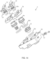
- Fig. 14 illustrates the fluid module 2 in an exploded view.
- the fluid module 2 comprises a body made up of a first body piece 2d and a second body piece 2e, that are secure to each other by means of screw joints, i.e. screws 13 and corresponding bolts (not shown).
- the first body piece 2d and the second body piece 2e are each provided with a first bore 3i and a second bore 5i.
- the bores 3i, 5i are through bores that extends perpendicularly through the bodies of the first body piece 2d and the second body piece 2e.
- the first body piece 2d and the second body piece 2e are aligned such that the first bores 3i and the second bores 5i are coaxial, respectively.
- the first bore 3i in the first body piece 2d is fitted with the socket 3j and a gasket 10c, 10d at each end thereof.
- the first tube 3a is fitted inside the socket 3j.
- the second bore 5i in the first body piece 2d is fitted with a gasket 10a and the second tube 5a.
- the bores 3i, 5i of the second body piece 2e are fitted over the respective first tube 3a and second tube 5a.
- a gasket 10e is fitted inside the first bore 3i, and the product line (not shown) is secured to the fluid module 2 with the first bond 8.
- Another gasket 10b is fitted inside the second bore 5i, and the drain line (not shown) is secured to the fluid module 2 with a first tube 3a with the second bond 9.
- Fig. 15 illustrates cross-sectional view of the door 20 in Fig. 9 along a plane depicted by C-C.
- the door 20 is used for sealing the cleaning/disinfection loop and for protecting the ports 3, 5 when not in use.
- the seals 21, 22 of the door 20 may be silicon seals.
- the seals 21, 22 seal the flow block during disinfection.
- the seals 21, 22 may be the same kind of seal but oppositely arranged.
- a seal 21, 22 comprises a cylinder shaped body with two oppositely arranged surfaces. One side of the body is provided with a first rim encircling and perpendicularly extending from a first of the surfaces, i.e.
- the body is provided with two outer flanges that holds the seal 21, 22 to the inner wall 20d of the door 20.
- the outer flanges may be circumferential around the outer surface of the body. One of the outer flanges will also, when the door is in the closed position, debut against a seat 3d, 5d as has been previously explained.
- the door 20 comprises a front side 20c and an opposite inner wall 20d.
- the first seal 21 and the second seal 22 are arranged to the inner wall 20d.
- the inner wall 20d defines an axis that in the closed position is parallel with the end faces 3f, 5f of the tubes 3a, 5a, and parallel with the outer faces or ends of the seats 3d, 5d.
- the door 20 further comprises a spring-loaded latch assembly 25 for locking the door 20 to the fluid module 2, during cleaning/disinfection and protecting the ports 3, 5 when not in use.
- the latch is spring loaded to get a distinct and safe locking. When closing the door 20 the latch gives a distinct click sound when it is locked.
- the seals 21, 22 are positioned such that the seals will be in the correct position against the ports 3, 5 by support from the outer side of the door 20 and a minor compression of the silicon rubber seals 21, 22 approximately 0.5 mm, when the door 20 is closed against the fluid module 2.
- the latch assembly 25 comprises a lever 25a, a spring 23b, a door spring seat 23a and a pin 23c.
- the lever 25a comprises a hook 25b arranged perpendicular to the main extension of the lever 25a, a pin passage 25c arranged with the pin 23c in the passage 25c or hole acting as a pivot point for the lever 25a, a spring seat 25d holding a spring 23b against a spring seat 23a of the door 20, arranged to the inner wall 20d.
- a spring force of the spring 23b maintains the hook 25b against the fluid module 2 when the door 20 is in the closed position.
- the door 20 further comprises an additional spring arrangement 26.
- the additional spring arrangement 26 assures that when the door 20 is not locked, the door 20 will be distanced from the fluid module 2 such that the sensor arrangement 50 will not detect the presence of the door 20 and erroneously report that the door 20 is closed.
- This spring arrangement 26 comprises a spring 28 arranged between a spring seat 27 of the door 20 and the second seal 22.
- the spring 28 is provided in a space 22a of the second seal 22, delimited by an inner side 22b of a rim of the second seal 22.
- the second seal 22 is being biased by the spring 28 against an incision 29 of an inner side of the inner wall 20d of the door 20 with a flange of the second seal 22, with a predetermined spring force.
- the incision 29 may be circumferential around the second seal 22.
- the second seal 22 is being movable a distance ⁇ d against the spring seat 27 by overcoming the spring force.
- the distance ⁇ d may be between 2 and 5 mm, e.g. 3 mm.
- the spring 28 opens the door 20 approximately 3 mm. This is enough for the door sensor arrangemnent 50 to loose the signal from the magnet in the door 20.
- the magnet is provided in the second body part 20a.
- a gasket may be provided to reduce the wear from the spring end against the second seal 22.
- the seals 21, 22 have two different sides to be able to fulfill both sealing criteria with the same part.
- the first port 3, i.e. a product water port or purified water port needs high flow volume to clean efficient and the second port 5, i.e. a drain port, needs higher flow speed to reduce the remaining fluid after disinfection.
- the first seal 21 and/or the second seal 22 may be arranged with an irregular outer surface 22c.
- An irregular surface may promote distribution of fluid, which promotes a complete cleaning of the port arrangement 1.
- the irregular outer surface 22c comprises one or several recesses, e.g. a recess shaped as a cross as shown e.g. in Fig. 3 .
- the recessed cross essentially covers the outer surface 22c of the second seal 22.
- the second seal 22 is provided with a rim circumferential about the irregular outer surface 22c.
- the rim extends perpendicularly from the outer surface 22c, and mates with the seat 5d.
- the first seal 21 is also provided with a circumferential rim mating with the seat 3d.
- the rim encircles an interior surface 21b and a space 21a in the first seal 21.
- the space 21a gives room for fluid such that a larger flow of cleaning fluid can be accommodated.
- the disclosure also relates to a method for performing port cleaning of a water producing apparatus, e.g. the water producing apparatus 100 that has been previously explained.
- the method may be implemented as a computer program comprising instructions which, when the program is executed by the control unit 112, cause the control unit 112 and the thereto associated water producing apparatus 100 to carry out the method.
- the disclosure further relates to a computer-readable medium comprising instruction which, when executed by the control unit 112, cause the control unit 112 and the thereto associated water producing apparatus 100 to carry out the method.
- the method may comprise receiving S0 a door position signal indicating that the door 20 is closed.
- the method further comprises producing S1, or rather causing the fluid circuit (e.g. the fluid circuit 103) to produce, a cleaning fluid.
- the cleaning fluid may be purified water, heated purified water, purified water with a cleaning agent or heated purified water with a cleaning agent.
- the cleaning agent may be citric acid or derivatives thereof.
- the cleaning agent may be added to the fluid circuit via a cleaning agent port (not shown) connected to the fluid circuit.
- the producing S1 may comprise producing a heated cleaning fluid.
- the method further comprises passing S2 the cleaning fluid (thus controlling the cleaning fluid to flow) through the first port 3 via the first tube 3a to the first circumferential space 3c, from the first circumferential space 3c via the bypass channel 7 to the second circumferential space 5c, and thereafter to the second tube 5a.
- the cleaning fluid is directed or controlled to flow through the product line 108 by pumping with the pump P and controlling appropriate valve such as the valve device 107 in order to direct the cleaning fluid in the desired direction.
- the method further comprises passing S3 the cleaning fluid from the second tube 5a to the drain, e.g. via the drain line 109.
- the passing S2 comprises passing the cleaning fluid during a certain time period meeting a cleaning criterion for the first port 3 and the second port 5.
- the cleaning criterion may include temperature and/or time duration for the cleaning.
- the method comprises checking whether a cleaning criterion has been fulfilled. If the cleaning criterion has not been fulfilled, the method returns to step S0 or S1. The port cleaning continues until the cleaning criterion has been fulfilled. If the cleaning criterion has been fulfilled, the cleaning of the ports is stopped S5, and the production of cleaning fluid is stopped.
Landscapes
- Health & Medical Sciences (AREA)
- Heart & Thoracic Surgery (AREA)
- Engineering & Computer Science (AREA)
- Life Sciences & Earth Sciences (AREA)
- Urology & Nephrology (AREA)
- Veterinary Medicine (AREA)
- Public Health (AREA)
- Anesthesiology (AREA)
- Biomedical Technology (AREA)
- Hematology (AREA)
- Animal Behavior & Ethology (AREA)
- General Health & Medical Sciences (AREA)
- Chemical & Material Sciences (AREA)
- Vascular Medicine (AREA)
- Emergency Medicine (AREA)
- Epidemiology (AREA)
- Pulmonology (AREA)
- Hydrology & Water Resources (AREA)
- Medicinal Chemistry (AREA)
- Environmental & Geological Engineering (AREA)
- Organic Chemistry (AREA)
- Water Supply & Treatment (AREA)
- Separation Using Semi-Permeable Membranes (AREA)
- External Artificial Organs (AREA)
- Cleaning In General (AREA)
Claims (15)
- Öffnungsanordnung (1), umfassend:- ein Fluidmodul (2) mit∘ einer ersten Öffnung (3), die dazu angeordnet ist, einen ersten Verbinder (4) aufzunehmen, wobei die erste Öffnung (3) ein erstes Rohr (3a) und eine erste Innenwand (3b), die zum ersten Rohr (3a) konzentrisch ist, umfasst, wobei die erste Innenwand (3b) einen ersten Umfangsraum (3c) um das erste Rohr (3a) vorsieht, wobei die erste Öffnung (3) ferner eine erste Aufnahme (3d) umfasst, die sich von der ersten Innenwand (3b) erstreckt, um ein vorderes Ende (3k) der ersten Öffnung (3) auszubilden;∘ einer zweiten Öffnung (5), die dazu angeordnet ist, einen zweiten Verbinder (6) aufzunehmen, wobei die zweite Öffnung (5) ein zweites Rohr (5a) und eine zweite Innenwand (5b), die zum zweiten Rohr (5a) konzentrisch ist, umfasst, wobei die zweite Innenwand (5b) einen zweiten Umfangsraum (5c) um das zweite Rohr (5c) vorsieht, wobei die zweite Öffnung (5) ferner eine zweite Aufnahme (5d) umfasst, die sich von der zweiten Innenwand (5b) erstreckt, um ein vorderes Ende (5k) der zweiten Öffnung (5) auszubilden;∘ einem Bypasskanal (7), der den ersten Umfangsraum (3c) mit dem zweiten Umfangsraum (5c) verbindet;- eine Klappe (20), umfassend eine erste Dichtung (21) und eine zweite Dichtung (22), die an einer Innenwand (20d) der Klappe (20) angeordnet sind, wobei die Klappe (20) dazu angeordnet ist, in einer geschlossenen Position gegen das Fluidmodul (2) positioniert zu sein, wobei die erste Dichtung (21) und die zweite Dichtung (22) derart an der Innenwand (20d) positioniert sind, dass die erste Dichtung (21) in der geschlossenen Position an der ersten Aufnahme (3d) anliegt und die zweite Dichtung (22) an der zweiten Aufnahme (5d) anliegt, um dadurch den ersten Umfangsraum (3c) und den zweiten Umfangsraum (5c) abzudichten.
- Öffnungsanordnung (1) nach Anspruch 1, wobei der Bypasskanal (7) an einem inneren Boden des Umfangsraums (3c) mit dem ersten Umfangsraum (3c) verbunden ist und wobei der Bypasskanal (7) an einem inneren Boden des Umfangsraums (5c) mit dem zweitem Umfangsraum (5c) verbunden ist.
- Öffnungsanordnung (1) nach Anspruch 1 oder 2, wobei die erste Dichtung (21) in der geschlossenen Position von einer Endfläche (3f) des ersten Rohrs (3a) beabstandet ist und die zweite Dichtung (22) von einer Endfläche (5f) des zweiten Rohrs (5a) beabstandet ist.
- Öffnungsanordnung (1) nach einem der vorstehenden Ansprüche, wobei die erste Öffnung (3) dazu angeordnet ist, den ersten Verbinder (4) am vorderen Ende (3k) der ersten Öffnung (3) aufzunehmen und an einem hinteren Ende (3g) der ersten Öffnung (3) mit einer Produktleitung (108) verbunden zu sein; und wobei die zweite Öffnung (5), dazu angeordnet ist, den zweiten Verbinder (6) am vorderen Ende (5k) der zweiten Öffnung (5) aufzunehmen und an einem hinteren Ende (5g) der zweiten Öffnung (5) mit einer Abflussleitung (109) verbunden zu sein.
- Öffnungsanordnung (1) nach einem der vorstehenden Ansprüche, wobei die erste Öffnung (3) und die zweite Öffnung (5) als konische Anschlussstücke vom Typ Luer gestaltet sind.
- Öffnungsanordnung (1) nach einem der vorstehenden Ansprüche, wobei das zweite Rohr (5a) eine mit einem Gewinde versehene Außenseite (5e) aufweist.
- Öffnungsanordnung (1) nach einem der vorstehenden Ansprüche, wobei die erste Innenwand (3b) mit einem Gewinde versehen ist.
- Öffnungsanordnung (1) nach einem der vorstehenden Ansprüche, wobei der Bypasskanal (7) eine Hauptbohrung (7a), einen ersten umlaufenden Spalt (7b) um das erste Rohr (3a), der eine Verbindung zum Umfangsraum (3c) herstellt, einen zweiten umlaufenden Spalt (7d) um das zweite Rohr (5a), der eine Verbindung mit dem zweiten Raum (5c) herstellt, umfasst, wobei die Hauptbohrung (7a) den ersten umlaufenden Spalt (7b) mit dem zweiten umlaufenden Spalt (7d) verbindet.
- Öffnungsanordnung (1) nach einem der vorstehenden Ansprüche, wobei der Bypasskanal (7) einen dritten umlaufenden Spalt (7d) umfasst, der mit dem zweiten Raum (5c) und mit der Hauptbohrung (7a) verbunden ist.
- Öffnungsanordnung (1) nach einem der vorstehenden Ansprüche, wobei die Klappe (20) ferner eine Federanordnung (26) mit einer Feder (28), die zwischen einer Federaufnahme (27) der Klappe (20) und der zweiten Dichtung (22) angeordnet ist, umfasst, wobei die zweite Dichtung (22) durch die Feder (28) gegen einen Einschnitt (29) einer Innenwand (20c) der Klappe (20) mit einer festgelegten Federkraft vorgespannt ist, wobei die zweite Dichtung (22) um eine Entfernung Δd entgegen der Federaufnahme (27) durch Überwinden der Federkraft beweglich ist.
- Öffnungsanordnung (1) nach einem der vorstehenden Ansprüche, wobei die erste Dichtung (21) und/oder die zweite Dichtung (22) mit einer unregelmäßigen Fläche (22c) angeordnet ist, um die Verteilung von Fluid zu fördern.
- Vorrichtung (100) zur Herstellung von gereinigtem Wasser, umfassend• ein Gehäuse (101);• einen Fluidkreislauf (103), der innerhalb des Gehäuses (103) umschlossen und dazu angeordnet ist, eine Strömung aus gereinigtem Wasser aus einer Wasserquelle (200) herzustellen und verbrauchtes Fluid zu einem Abfluss (202) zu transportieren;• eine Öffnungsanordnung (1) nach einem der vorstehenden Ansprüche, wobei die Öffnungsanordnung (1) derart am Gehäuse (101) angeordnet ist, dass die Klappe (20), das vordere Ende (3k) der ersten Öffnung (3) und das vordere Ende (5k) der zweiten Öffnung (5) von außerhalb der Wasserherstellungsvorrichtung (100) zugänglich sind, um eine Fluidverbindung des ersten Verbinders (4) und des zweiten Verbinders (6) zuzulassen, und wobei die erste Öffnung (3) und die zweite Öffnung (5) an jeweiligen hinteren Enden (3g, 5g) der Öffnungen (3, 5) mit dem Fluidkreislauf (Z2) fluidisch verbunden sind.
- Wasserherstellungsvorrichtung (100) nach Anspruch 12, umfassend eine Steuereinheit (112), die dazu angeordnet ist, ein Klappenpositionssignal zu empfangen, das die Position der Klappe (20) anzeigt, und wobei die Wasserherstellungsvorrichtung (100) dazu angeordnet ist, eine Strömung von Reinigungsfluid zur Öffnungsanordnung (1) auf Grundlage der Position der Klappe (20) zu steuern.
- Wasserherstellungsvorrichtung (100) nach Anspruch 12 oder 13, wobei die Wasserherstellungsvorrichtung (100) dazu angeordnet ist, Reinigungsfluid zum hinteren Ende (3g) der ersten Öffnung (3) zu leiten, wenn das Klappenpositionssignal anzeigt, dass sich die Klappe (20) in einer geschlossenen Position befindet, wobei das Reinigungsfluid in das erste Rohr (3a) eintritt und in den ersten Raum (3c) der ersten Öffnung (3), anschließend über den Bypasskanal (7) zum zweiten Raum (5c) und in das zweite Rohr (5c) strömt, woraufhin das Reinigungsfluid die zweite Öffnung (5) über das hintere Ende (5g) der zweiten Öffnung (5) verlässt und über den Fluidkreislauf (103) weiter zum Abfluss (202) transportiert wird.
- Verfahren zum Ausführen der Öffnungsreinigung einer Wasserherstellungsvorrichtung (100) nach einem der Ansprüche 12 bis 14, wobei das Verfahren Folgendes umfasst:- Herstellen (S1) eines Reinigungsfluids mit dem Fluidkreislauf;- Strömen (S2) des Reinigungsfluids durch die erste Öffnung (3) über das erste Rohr (3a) zum ersten Umfangsraum (3c), vom ersten Umfangsraum (3c) über den Bypasskanal (7) zum zweiten Umfangsraum (5c) und anschließend zum zweiten Rohr (5a);- Strömen (S3) des Reinigungsfluids vom zweiten Rohr (5a) zum Abfluss.
Applications Claiming Priority (2)
| Application Number | Priority Date | Filing Date | Title |
|---|---|---|---|
| SE1751357 | 2017-11-01 | ||
| PCT/EP2018/079279 WO2019086321A1 (en) | 2017-11-01 | 2018-10-25 | A port arrangement, a purified water producing apparatus comprising the port arrangement and a method for performing port cleaning of a purified water producing apparatus |
Publications (2)
| Publication Number | Publication Date |
|---|---|
| EP3703773A1 EP3703773A1 (de) | 2020-09-09 |
| EP3703773B1 true EP3703773B1 (de) | 2024-11-27 |
Family
ID=64051546
Family Applications (1)
| Application Number | Title | Priority Date | Filing Date |
|---|---|---|---|
| EP18795977.0A Active EP3703773B1 (de) | 2017-11-01 | 2018-10-25 | Öffnungsanordnung, vorrichtung zur herstellung von gereinigtem wasser mit der öffnungsanordnung und verfahren zur öffnungsreinigung einer vorrichtung zur herstellung von gereinigtem wasser |
Country Status (7)
| Country | Link |
|---|---|
| US (3) | US11931495B2 (de) |
| EP (1) | EP3703773B1 (de) |
| JP (1) | JP7223359B2 (de) |
| CN (1) | CN111405916B (de) |
| CA (1) | CA3079863A1 (de) |
| ES (1) | ES3012385T3 (de) |
| WO (1) | WO2019086321A1 (de) |
Families Citing this family (5)
| Publication number | Priority date | Publication date | Assignee | Title |
|---|---|---|---|---|
| JP7332016B2 (ja) * | 2019-11-18 | 2023-08-23 | ニプロ株式会社 | アダプタ |
| DE102020106593A1 (de) * | 2020-03-11 | 2021-09-16 | Fresenius Medical Care Deutschland Gmbh | Reinigungsvorrichtung und Reinigungssystem für eine Blutbehandlungsvorrichtung |
| DE102020106590A1 (de) | 2020-03-11 | 2021-09-16 | Fresenius Medical Care Deutschland Gmbh | Konnektionselement und Konnektionssystem für eine Blutbehandlungsvorrichtung |
| DE102020126224A1 (de) * | 2020-10-07 | 2022-04-07 | Fresenius Medical Care Deutschland Gmbh | Zugangssystem für ein medizintechnisches Gerät zur Entnahme einer medizinischen Flüssigkeit und Überwachungssystem mit einem derartigen Zugangssystem und ein medizinisches Behandlungsgerät mit einem derartigen Überwachungssystem |
| US20250213765A1 (en) * | 2023-12-29 | 2025-07-03 | Baxter International Inc. | Elastomeric door for medical fluid treatment machine |
Family Cites Families (16)
| Publication number | Priority date | Publication date | Assignee | Title |
|---|---|---|---|---|
| US5275724A (en) * | 1991-12-10 | 1994-01-04 | Millipore Corporation | Connector apparatus and system |
| US5591344A (en) | 1995-02-13 | 1997-01-07 | Aksys, Ltd. | Hot water disinfection of dialysis machines, including the extracorporeal circuit thereof |
| SE9901165D0 (sv) * | 1999-03-30 | 1999-03-30 | Gambro Lundia Ab | Method, apparatus and components of dialysis systems |
| PT1642614E (pt) | 2002-03-11 | 2010-02-15 | Fresenius Medical Care De Gmbh | Recipiente com um conector e um dispositivo de preparação de fluido de diálise associado |
| US7390316B2 (en) * | 2003-08-08 | 2008-06-24 | Teleflex Medical Incorporated | Seal positioning assembly |
| ITBO20070811A1 (it) | 2007-12-10 | 2009-06-11 | Sorin Group Italia Srl | Gruppo di infusione di una soluzione di sostituzione da una macchina di dialisi |
| JP2010187721A (ja) | 2009-02-16 | 2010-09-02 | Daicen Membrane Systems Ltd | 人工透析用水の供給装置 |
| US8434511B2 (en) * | 2009-07-08 | 2013-05-07 | Gt Advanced Cz Llc | Retractable and expandable water cooled valve gate useful for sealing a hot processing chamber |
| US8617465B2 (en) | 2009-09-15 | 2013-12-31 | Baxter International Inc. | Dialysis connector and cap compatible with gas sterilization |
| US9861733B2 (en) * | 2012-03-23 | 2018-01-09 | Nxstage Medical Inc. | Peritoneal dialysis systems, devices, and methods |
| JP5205496B2 (ja) | 2011-07-27 | 2013-06-05 | 日機装株式会社 | 透析液取出装置 |
| DE102012005189A1 (de) | 2012-03-16 | 2013-09-19 | Fresenius Medical Care Deutschland Gmbh | Medizinische Vorrichting mit einer Buchsen-Einheit zum Anschluss einer Vorrichtung zur Bereitstellung von medizinischen Flüssigkeiten |
| JP5479520B2 (ja) | 2012-04-05 | 2014-04-23 | 日機装株式会社 | 透析液取出装置 |
| JP5920575B2 (ja) * | 2012-06-13 | 2016-05-18 | ニプロ株式会社 | 接続ポートおよび接続ポートを備えた透析装置 |
| EP2883566B1 (de) * | 2013-12-11 | 2017-05-24 | Gambro Lundia AB | Extrakorporales Blutbehandlungssystem und Ventileinheit für Prädilution und Postdilution |
| DE102014108227A1 (de) * | 2014-06-12 | 2015-12-17 | B. Braun Avitum Ag | Dialysemaschinen-integrierte Substitutionspumpe |
-
2018
- 2018-10-25 EP EP18795977.0A patent/EP3703773B1/de active Active
- 2018-10-25 WO PCT/EP2018/079279 patent/WO2019086321A1/en not_active Ceased
- 2018-10-25 US US16/760,575 patent/US11931495B2/en active Active
- 2018-10-25 CA CA3079863A patent/CA3079863A1/en active Pending
- 2018-10-25 ES ES18795977T patent/ES3012385T3/es active Active
- 2018-10-25 CN CN201880071406.5A patent/CN111405916B/zh active Active
- 2018-10-25 JP JP2020519768A patent/JP7223359B2/ja active Active
-
2024
- 2024-03-07 US US18/598,898 patent/US12285551B2/en active Active
-
2025
- 2025-04-28 US US19/191,874 patent/US20250312522A1/en active Pending
Also Published As
| Publication number | Publication date |
|---|---|
| JP7223359B2 (ja) | 2023-02-16 |
| EP3703773A1 (de) | 2020-09-09 |
| US11931495B2 (en) | 2024-03-19 |
| US20250312522A1 (en) | 2025-10-09 |
| CN111405916A (zh) | 2020-07-10 |
| US20240207497A1 (en) | 2024-06-27 |
| WO2019086321A1 (en) | 2019-05-09 |
| CN111405916B (zh) | 2023-09-19 |
| CA3079863A1 (en) | 2019-05-09 |
| ES3012385T3 (en) | 2025-04-09 |
| US12285551B2 (en) | 2025-04-29 |
| JP2021500945A (ja) | 2021-01-14 |
| US20200345917A1 (en) | 2020-11-05 |
Similar Documents
| Publication | Publication Date | Title |
|---|---|---|
| US12285551B2 (en) | Port arrangement, a purified water producing apparatus comprising the port arrangement and a method for performing port cleaning of a purified water producing apparatus | |
| US12134076B2 (en) | Water purification apparatus and methods for cleaning the water purification apparatus | |
| JP7418039B2 (ja) | 浄水装置および浄水装置における少なくとも1つの流体特性を制御する方法 | |
| US20230202896A9 (en) | A system and a method for producing microbiologically controlled fluid | |
| EA026018B1 (ru) | Система для осуществления процесса лечения диализом | |
| US11951241B2 (en) | Peritoneal dialysis system and methods | |
| JP2019532753A (ja) | 容易にアクセス可能な空気圧マニホールドおよびその弁を含む医療流体治療機械 | |
| CN111867649B (zh) | 具有局部消毒的透析系统 | |
| US20240189777A1 (en) | Water purification apparatus and methods for cleaning the water purification apparatus |
Legal Events
| Date | Code | Title | Description |
|---|---|---|---|
| STAA | Information on the status of an ep patent application or granted ep patent |
Free format text: STATUS: UNKNOWN |
|
| STAA | Information on the status of an ep patent application or granted ep patent |
Free format text: STATUS: THE INTERNATIONAL PUBLICATION HAS BEEN MADE |
|
| PUAI | Public reference made under article 153(3) epc to a published international application that has entered the european phase |
Free format text: ORIGINAL CODE: 0009012 |
|
| STAA | Information on the status of an ep patent application or granted ep patent |
Free format text: STATUS: REQUEST FOR EXAMINATION WAS MADE |
|
| 17P | Request for examination filed |
Effective date: 20200602 |
|
| AK | Designated contracting states |
Kind code of ref document: A1 Designated state(s): AL AT BE BG CH CY CZ DE DK EE ES FI FR GB GR HR HU IE IS IT LI LT LU LV MC MK MT NL NO PL PT RO RS SE SI SK SM TR |
|
| AX | Request for extension of the european patent |
Extension state: BA ME |
|
| DAV | Request for validation of the european patent (deleted) | ||
| DAX | Request for extension of the european patent (deleted) | ||
| GRAP | Despatch of communication of intention to grant a patent |
Free format text: ORIGINAL CODE: EPIDOSNIGR1 |
|
| STAA | Information on the status of an ep patent application or granted ep patent |
Free format text: STATUS: GRANT OF PATENT IS INTENDED |
|
| INTG | Intention to grant announced |
Effective date: 20240603 |
|
| GRAS | Grant fee paid |
Free format text: ORIGINAL CODE: EPIDOSNIGR3 |
|
| GRAA | (expected) grant |
Free format text: ORIGINAL CODE: 0009210 |
|
| STAA | Information on the status of an ep patent application or granted ep patent |
Free format text: STATUS: THE PATENT HAS BEEN GRANTED |
|
| AK | Designated contracting states |
Kind code of ref document: B1 Designated state(s): AL AT BE BG CH CY CZ DE DK EE ES FI FR GB GR HR HU IE IS IT LI LT LU LV MC MK MT NL NO PL PT RO RS SE SI SK SM TR |
|
| REG | Reference to a national code |
Ref country code: GB Ref legal event code: FG4D |
|
| REG | Reference to a national code |
Ref country code: CH Ref legal event code: EP |
|
| REG | Reference to a national code |
Ref country code: IE Ref legal event code: FG4D |
|
| REG | Reference to a national code |
Ref country code: DE Ref legal event code: R096 Ref document number: 602018077027 Country of ref document: DE |
|
| REG | Reference to a national code |
Ref country code: LT Ref legal event code: MG9D |
|
| REG | Reference to a national code |
Ref country code: NL Ref legal event code: MP Effective date: 20241127 |
|
| REG | Reference to a national code |
Ref country code: ES Ref legal event code: FG2A Ref document number: 3012385 Country of ref document: ES Kind code of ref document: T3 Effective date: 20250409 |
|
| PG25 | Lapsed in a contracting state [announced via postgrant information from national office to epo] |
Ref country code: HR Free format text: LAPSE BECAUSE OF FAILURE TO SUBMIT A TRANSLATION OF THE DESCRIPTION OR TO PAY THE FEE WITHIN THE PRESCRIBED TIME-LIMIT Effective date: 20241127 Ref country code: PT Free format text: LAPSE BECAUSE OF FAILURE TO SUBMIT A TRANSLATION OF THE DESCRIPTION OR TO PAY THE FEE WITHIN THE PRESCRIBED TIME-LIMIT Effective date: 20250327 Ref country code: IS Free format text: LAPSE BECAUSE OF FAILURE TO SUBMIT A TRANSLATION OF THE DESCRIPTION OR TO PAY THE FEE WITHIN THE PRESCRIBED TIME-LIMIT Effective date: 20250327 |
|
| PG25 | Lapsed in a contracting state [announced via postgrant information from national office to epo] |
Ref country code: FI Free format text: LAPSE BECAUSE OF FAILURE TO SUBMIT A TRANSLATION OF THE DESCRIPTION OR TO PAY THE FEE WITHIN THE PRESCRIBED TIME-LIMIT Effective date: 20241127 Ref country code: NL Free format text: LAPSE BECAUSE OF FAILURE TO SUBMIT A TRANSLATION OF THE DESCRIPTION OR TO PAY THE FEE WITHIN THE PRESCRIBED TIME-LIMIT Effective date: 20241127 |
|
| REG | Reference to a national code |
Ref country code: AT Ref legal event code: MK05 Ref document number: 1745107 Country of ref document: AT Kind code of ref document: T Effective date: 20241127 |
|
| PG25 | Lapsed in a contracting state [announced via postgrant information from national office to epo] |
Ref country code: BG Free format text: LAPSE BECAUSE OF FAILURE TO SUBMIT A TRANSLATION OF THE DESCRIPTION OR TO PAY THE FEE WITHIN THE PRESCRIBED TIME-LIMIT Effective date: 20241127 |
|
| PG25 | Lapsed in a contracting state [announced via postgrant information from national office to epo] |
Ref country code: NO Free format text: LAPSE BECAUSE OF FAILURE TO SUBMIT A TRANSLATION OF THE DESCRIPTION OR TO PAY THE FEE WITHIN THE PRESCRIBED TIME-LIMIT Effective date: 20250227 |
|
| PG25 | Lapsed in a contracting state [announced via postgrant information from national office to epo] |
Ref country code: GR Free format text: LAPSE BECAUSE OF FAILURE TO SUBMIT A TRANSLATION OF THE DESCRIPTION OR TO PAY THE FEE WITHIN THE PRESCRIBED TIME-LIMIT Effective date: 20250228 Ref country code: LV Free format text: LAPSE BECAUSE OF FAILURE TO SUBMIT A TRANSLATION OF THE DESCRIPTION OR TO PAY THE FEE WITHIN THE PRESCRIBED TIME-LIMIT Effective date: 20241127 Ref country code: AT Free format text: LAPSE BECAUSE OF FAILURE TO SUBMIT A TRANSLATION OF THE DESCRIPTION OR TO PAY THE FEE WITHIN THE PRESCRIBED TIME-LIMIT Effective date: 20241127 |
|
| PG25 | Lapsed in a contracting state [announced via postgrant information from national office to epo] |
Ref country code: PL Free format text: LAPSE BECAUSE OF FAILURE TO SUBMIT A TRANSLATION OF THE DESCRIPTION OR TO PAY THE FEE WITHIN THE PRESCRIBED TIME-LIMIT Effective date: 20241127 |
|
| PG25 | Lapsed in a contracting state [announced via postgrant information from national office to epo] |
Ref country code: RS Free format text: LAPSE BECAUSE OF FAILURE TO SUBMIT A TRANSLATION OF THE DESCRIPTION OR TO PAY THE FEE WITHIN THE PRESCRIBED TIME-LIMIT Effective date: 20250227 |
|
| PG25 | Lapsed in a contracting state [announced via postgrant information from national office to epo] |
Ref country code: SM Free format text: LAPSE BECAUSE OF FAILURE TO SUBMIT A TRANSLATION OF THE DESCRIPTION OR TO PAY THE FEE WITHIN THE PRESCRIBED TIME-LIMIT Effective date: 20241127 |
|
| PG25 | Lapsed in a contracting state [announced via postgrant information from national office to epo] |
Ref country code: DK Free format text: LAPSE BECAUSE OF FAILURE TO SUBMIT A TRANSLATION OF THE DESCRIPTION OR TO PAY THE FEE WITHIN THE PRESCRIBED TIME-LIMIT Effective date: 20241127 |
|
| PG25 | Lapsed in a contracting state [announced via postgrant information from national office to epo] |
Ref country code: EE Free format text: LAPSE BECAUSE OF FAILURE TO SUBMIT A TRANSLATION OF THE DESCRIPTION OR TO PAY THE FEE WITHIN THE PRESCRIBED TIME-LIMIT Effective date: 20241127 |
|
| PG25 | Lapsed in a contracting state [announced via postgrant information from national office to epo] |
Ref country code: RO Free format text: LAPSE BECAUSE OF FAILURE TO SUBMIT A TRANSLATION OF THE DESCRIPTION OR TO PAY THE FEE WITHIN THE PRESCRIBED TIME-LIMIT Effective date: 20241127 |
|
| PG25 | Lapsed in a contracting state [announced via postgrant information from national office to epo] |
Ref country code: SK Free format text: LAPSE BECAUSE OF FAILURE TO SUBMIT A TRANSLATION OF THE DESCRIPTION OR TO PAY THE FEE WITHIN THE PRESCRIBED TIME-LIMIT Effective date: 20241127 |
|
| PG25 | Lapsed in a contracting state [announced via postgrant information from national office to epo] |
Ref country code: CZ Free format text: LAPSE BECAUSE OF FAILURE TO SUBMIT A TRANSLATION OF THE DESCRIPTION OR TO PAY THE FEE WITHIN THE PRESCRIBED TIME-LIMIT Effective date: 20241127 |
|
| REG | Reference to a national code |
Ref country code: DE Ref legal event code: R097 Ref document number: 602018077027 Country of ref document: DE |
|
| PG25 | Lapsed in a contracting state [announced via postgrant information from national office to epo] |
Ref country code: SE Free format text: LAPSE BECAUSE OF FAILURE TO SUBMIT A TRANSLATION OF THE DESCRIPTION OR TO PAY THE FEE WITHIN THE PRESCRIBED TIME-LIMIT Effective date: 20241127 |
|
| PLBE | No opposition filed within time limit |
Free format text: ORIGINAL CODE: 0009261 |
|
| STAA | Information on the status of an ep patent application or granted ep patent |
Free format text: STATUS: NO OPPOSITION FILED WITHIN TIME LIMIT |
|
| PGFP | Annual fee paid to national office [announced via postgrant information from national office to epo] |
Ref country code: IT Payment date: 20250923 Year of fee payment: 8 |
|
| PGFP | Annual fee paid to national office [announced via postgrant information from national office to epo] |
Ref country code: GB Payment date: 20250923 Year of fee payment: 8 |
|
| PGFP | Annual fee paid to national office [announced via postgrant information from national office to epo] |
Ref country code: FR Payment date: 20250924 Year of fee payment: 8 |
|
| 26N | No opposition filed |
Effective date: 20250828 |
|
| REG | Reference to a national code |
Ref country code: GB Ref legal event code: 732E Free format text: REGISTERED BETWEEN 20251030 AND 20251105 |
|
| PGFP | Annual fee paid to national office [announced via postgrant information from national office to epo] |
Ref country code: DE Payment date: 20250923 Year of fee payment: 8 |
|
| PGFP | Annual fee paid to national office [announced via postgrant information from national office to epo] |
Ref country code: ES Payment date: 20251103 Year of fee payment: 8 |