EP3703183B1 - Vorrichtung zum umsetzen eines elektrischen signals in eine mechanische bewegung - Google Patents
Vorrichtung zum umsetzen eines elektrischen signals in eine mechanische bewegung Download PDFInfo
- Publication number
- EP3703183B1 EP3703183B1 EP20154315.4A EP20154315A EP3703183B1 EP 3703183 B1 EP3703183 B1 EP 3703183B1 EP 20154315 A EP20154315 A EP 20154315A EP 3703183 B1 EP3703183 B1 EP 3703183B1
- Authority
- EP
- European Patent Office
- Prior art keywords
- fusible wire
- contact
- converting
- electrical signal
- clamp
- Prior art date
- Legal status (The legal status is an assumption and is not a legal conclusion. Google has not performed a legal analysis and makes no representation as to the accuracy of the status listed.)
- Active
Links
Images


Classifications
-
- H—ELECTRICITY
- H01—ELECTRIC ELEMENTS
- H01H—ELECTRIC SWITCHES; RELAYS; SELECTORS; EMERGENCY PROTECTIVE DEVICES
- H01H61/00—Electrothermal relays
- H01H61/04—Electrothermal relays wherein the thermally-sensitive member is only heated directly
-
- B—PERFORMING OPERATIONS; TRANSPORTING
- B64—AIRCRAFT; AVIATION; COSMONAUTICS
- B64G—COSMONAUTICS; VEHICLES OR EQUIPMENT THEREFOR
- B64G1/00—Cosmonautic vehicles
- B64G1/22—Parts of, or equipment specially adapted for fitting in or to, cosmonautic vehicles
- B64G1/64—Systems for coupling or separating cosmonautic vehicles or parts thereof, e.g. docking arrangements
- B64G1/645—Separators
- B64G1/6455—Pyrotechnics; Using heat
-
- B—PERFORMING OPERATIONS; TRANSPORTING
- B64—AIRCRAFT; AVIATION; COSMONAUTICS
- B64G—COSMONAUTICS; VEHICLES OR EQUIPMENT THEREFOR
- B64G1/00—Cosmonautic vehicles
- B64G1/22—Parts of, or equipment specially adapted for fitting in or to, cosmonautic vehicles
- B64G1/222—Parts of, or equipment specially adapted for fitting in or to, cosmonautic vehicles for deploying structures between a stowed and deployed state
- B64G1/2228—Parts of, or equipment specially adapted for fitting in or to, cosmonautic vehicles for deploying structures between a stowed and deployed state characterised by the hold-down or release mechanisms
-
- H—ELECTRICITY
- H02—GENERATION; CONVERSION OR DISTRIBUTION OF ELECTRIC POWER
- H02B—BOARDS, SUBSTATIONS OR SWITCHING ARRANGEMENTS FOR THE SUPPLY OR DISTRIBUTION OF ELECTRIC POWER
- H02B1/00—Frameworks, boards, panels, desks, casings; Details of substations or switching arrangements
- H02B1/18—Disposition or arrangement of fuses
Definitions
- the invention relates to a device for converting an electrical signal into a mechanical movement, in particular for triggering a triggering device that retains large forces, comprising at least one contacting device arranged in a base body and clamping a fusible wire, a securing bolt being fixed in a securing position by the fusible wire is.
- a release device having a segmented cylinder which grippingly retains an element to be decoupled at a point of application.
- the cylinder segments enclosing the point of application are secured by a winding to prevent the element to be decoupled from being disconnected and thus from being disconnected.
- the winding itself is fixed under pretension, for example by a fusible wire or a lever secured by fusible wire. If a commanded uncoupling of the element to be uncoupled is to be induced, a defined current pulse leads to the melting of the fuse wire, whereby the winding is released directly or via an external lever device and expands due to its internal stress.
- the cylinder segments can become detached from one another, thereby releasing the element to be decoupled.
- the disadvantage of the previously known solution is the fact that the assembly process of the device fixing the winding under prestress due to the large number of different Components is very complex and that the device for releasing the winding can only interact with a special design of the release device.
- the US9085377B2 also discloses a device having a plurality of segments of a cylinder for securing an element to be uncoupled, the cylinder segments being secured by a winding against being disconnected.
- the winding is fixed under pretension by a compact device having a lever, the lever being held in a holding position by a fusible wire.
- a current pulse is introduced, the fuse wire melts and the lever shifts from its holding position to a release position, which releases the pretensioning on the winding and releases the element to be decoupled after the cylinder segments have been separated.
- the CN107689476A also discloses a device for securing an element to be decoupled.
- the invention is therefore based on the object of proposing a device for converting an electrical signal into a mechanical movement, in particular for triggering a triggering device that retains large forces, which is safe despite a simple, compact construction and assembly can be operated, even if it has been exposed to extreme environmental influences over a long period of time.
- the invention achieves the stated problem in that the clamping force of the contacting device exerted on the fusible wire can be adjusted via a clamp which at least partially encompasses the base body.
- the device according to the invention has a base body which forms a receptacle for at least one contacting device.
- the contacting device grips one end of a fuse wire, for example made of cold-drawn stainless steel, and connects it to an externally controllable circuit.
- the second end of the fusible wire can be materially connected to the circuit, or, as stated in the dependent claims, contact can be made analogously to the first end.
- An uninsulated middle part of the fusible wire that is not clamped by the contacting device forms a loop that holds a securing bolt in a securing position.
- one end of the securing bolt is releasably fixed by the base body and the second end is passed through the loop of the fuse wire so that the securing bolt connected to a release device known from the prior art, for example, with a tensile strength, is fixed in its securing position.
- a release device known from the prior art, for example, with a tensile strength
- the securing bolt can fix a winding securing the cylinder segments under pretension.
- a low-resistance connection can be achieved between the contacting device, which is insulated towards the base body, and the fusible wire, and at the same time a large part of the uninsulated fusible wire can be protected from direct contact with corrosion media.
- the clamping force can be varied by differently positioning the clamp on the base body.
- the clamp also encloses the securing bolt, which also protects it from external forces that may act during a starting process and from unintentional actuation.
- the base body forms a receptacle for the at least one detachable contacting device.
- the connection of the contacting device to the fusible wire can be carried out outside the base body, after which the contacting device is inserted into the receptacle and the securing bolt is guided through the loop formed by the fusible wire.
- the securing bolt is connected to a triggering device known from the prior art, for example via a pulling means running transversely to the clamp.
- a triggering device can also be triggered by the device according to the invention via a lever.
- the securing bolt in its securing position, holds the lever which, for example, fixes a winding of a release device known from the prior art under pretension in a holding position.
- the safety bolt leaves its safety position, whereby the said lever is in a release position in which the winding is no longer fixed under pretension. transforms. As a result, the winding expands and releases the element to be decoupled.
- a lever mounted pivotably in the base body can be fixed in a holding position by means of a securing bolt secured by the fusible wire.
- the lever can be arranged in the base body in such a way that it is fixed in its holding position between the securing bolt and the base body.
- the clamp also encloses the lever, whereby an undesired actuation of the lever can be prevented.
- a current pulse leads to the melting of the fuse wire, after which the securing bolt fixing the lever in its holding position leaves its securing position. This in turn enables the lever to be shifted into a release position.
- the lever can form a shape adapted to the securing bolt.
- the contacting device form two contact tabs that can be detached from the base body and each clamp one end of the fusible wire, the fusible wire wrapping around the securing bolt at one of its end sections.
- the complete contacting of the fuse wire can be carried out outside the base body, which results in a particularly simple assembly process.
- the base body can form two receptacles so that the contact tabs can be guided out of and into the base body independently of one another.
- the contacting device forms two pairs of contact tabs, each having two contact tabs, which are detachable from the base body, the contact tabs of a first contact tab pair each clamping one end of a fusible wire looping around a first end section of the securing bolt, and the contact tabs of a second pair of contact tabs each clamp one end of a fuse wire wrapping around a second end section of the securing bolt.
- the securing bolt is fixed in its securing position exclusively by two fusible wires.
- the still functional system can initiate a current flow into the associated fusible wire, even if one circuit fails or if the contact has become inoperable, whereby the securing bolt can be brought out of its secured position and the lever activates the release device alternately from the holding position to the release position.
- the clamping force exerted by the clamp on the fusible wire can be adjusted by a threaded screw that displaces the opposite clamping tongues and connects them to one another.
- This has the advantage that the clamping force of the clamp changes independently of its internal stress and can be adjusted by means of defined torque specifications for the threaded screw.
- insulation adapted to the geometry of the terminal and acting as a clamping force distributor is provided between the contacting device and the terminal. Due to the positive connection both to the contact tabs arranged in the receptacle and to the terminal, a uniform distribution of force on the contacting device forming the contact tabs can be achieved.
- the insulation is detachably connected to the base body and at least partially encloses it.
- the insulation can form two insulating units, which are each arranged on one side of the base body between the contacting device forming the contact tabs and the terminal.
- the lever secured by the securing bolt is assigned a compression spring for assisted displacement from the holding position to a release position.
- the lever in its holding position, the lever can not only counteract a tensile force caused, for example, by a winding, but can also actively exert a compressive force.
- relatively large forces can be exerted or restrained so that the device according to the invention can counteract large forces or release elements to be uncoupled even without an interposed triggering device.
- the contact tab of a device comprising a connection receptacle for an electrical connection can form a fusible wire receptacle having two legs, which can be bent between an assembly position and an installation position, the fusible wire receptacle at the bending point arranged between the legs is penetrated by a threading hole.
- the legs of the fuse wire holder are spread apart so that the fuse wire can be inserted easily. By then bending the legs together, the fuse wire is held in the fuse wire holder.
- the force exerted by the legs on the fuse wire is sufficiently high to ensure a continuous fit even when the contact tab is inserted into the receptacle provided for this purpose in the base body, but allows the wire to be adjusted around the safety position of the fuse wire even after installation Align locking bolts.
- the contact tab points at the bending point
- the fuse wire holder has an accessible threading hole through which the end of the fuse wire is passed. By tightening the threaded end of the fusible wire, the dimensions of the loop can be adjusted and fixed by attaching the clamp that at least partially encloses the base body.
- the device according to the invention has, as in the Fig. 1 shown, a base body 1 made, for example, of high-performance plastic, such as polyetheretherketone, in which receptacles 2 are provided for a contacting device forming a plurality of contact tabs 3.
- Two contact tabs 3 each form a pair of contact tabs and each grip one end of a fuse wire 4 assigned to the contact tab pair, so that the part of the fuse wire 4 that is not enclosed by the contact tabs 3 forms a loop that loops around the end of a securing bolt 5 made of high-performance ceramics, for example.
- the contact tabs 3 are detachably connected to the receptacles 2, so that the difficult connection between fusible wire 4 and contact tabs 3 can be carried out independently of the base body 1.
- the pivotably mounted lever 6, made for example of aluminum bronze or other for materials known to those skilled in the art can be manufactured, brought into its holding position, after which the securing bolt 5 is passed through the loops of the fusible wires 4 so that the lever 6 between the base body 1 securing bolt 5 is fixed in its holding position.
- a terminal 7 made of, for example, spring steel, as is shown, for example, in FIG Fig. 2 can be seen, arranged on the base body 1, the clamping force of which can be adjusted by means of a threaded screw 8.
- an insulating unit 9 is arranged between each terminal 7 and the contact tabs 3.
- the insulation units 9, like the base body 1, can be made of polyetheretherketone (PEEK), for example.
- PEEK polyetheretherketone
- the insulating units 9 have grooves 10 acting as clamping force distributors and are designed towards the terminal 7 in such a way that a positive connection between the terminal 7 and the insulating units 9 results when a predetermined force is applied.
- the arrangement of the clamp 7 according to the invention provides additional protection for the securing bolt 5 and the lever 6, which prevents the device from being triggered unintentionally by any external forces.
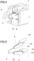
- the lever 6 To trigger a triggering device that retains large forces, the lever 6 must be in the Fig. 3 shown holding position in one of the Fig. 4 Skip the illustrated release position. This is done by a current pulse transmitted by one of the circuits, which leads to the melting of the corresponding fuse wire 4. If the fusible wires 4 are made of cold-drawn 1.4310 stainless steel and if they have a diameter of approximately 0.1 mm, the result is a resistance of approximately 2 ohms. The current pulse required to safely melt through the fuse wire 4 in this case is 4 A over a period of 30 ms. If the current is below 0.25 A, melting is impossible.
- the securing bolt 5 can no longer be held in its securing position, as a result of which the lever 6 is no longer that of a winding known from the prior art, for example Trigger device can counteract the force exerted and changes into its release position.
- the contact tabs 3 of a contact tab pair are each connected to a separate circuit, so that two independent circuits result for two contact tab pairs. This also enables the lever 6 to be shifted from its holding position to a release position if a pair of contact tabs or a circuit is defective.
- a compression spring 11 is provided to assist displacement of the lever 6 between that lever 6 and the base body 1.
- the lever 6 can also exert pressure forces, thereby expanding the range of triggering devices that can be used to release large forces.
- the device according to the invention can even be used to release large forces without a further triggering device having to be interposed.
- Fig. 5 shows a pair of contact tabs forming contact tabs 3.
- the contact tabs 3 have a fusible wire receptacle 12 forming two legs, which is located between an assembly position in which the legs are spread apart and an installation position in which the legs enclose the fusible wire 4, are bendable.
- the contact lugs 3 are penetrated by a threading hole 13 at the bending point between the legs, so that the threading-out ends of the fuse wire 4 are freely accessible.
- connection receptacles 14 In order to increase the resistance To increase the contact lugs, these are preferably made of nickel-plated copper.
Landscapes
- Engineering & Computer Science (AREA)
- Remote Sensing (AREA)
- Aviation & Aerospace Engineering (AREA)
- Fuses (AREA)
Priority Applications (1)
| Application Number | Priority Date | Filing Date | Title |
|---|---|---|---|
| PL20154315T PL3703183T3 (pl) | 2019-02-19 | 2020-01-29 | Urządzenie do przekształcania sygnału elektrycznego w ruch mechaniczny |
Applications Claiming Priority (1)
| Application Number | Priority Date | Filing Date | Title |
|---|---|---|---|
| ATA50122/2019A AT521967B1 (de) | 2019-02-19 | 2019-02-19 | Vorrichtung zum Umsetzen eines elektrischen Signals in eine mechanische Bewegung |
Publications (2)
| Publication Number | Publication Date |
|---|---|
| EP3703183A1 EP3703183A1 (de) | 2020-09-02 |
| EP3703183B1 true EP3703183B1 (de) | 2021-09-15 |
Family
ID=69400409
Family Applications (1)
| Application Number | Title | Priority Date | Filing Date |
|---|---|---|---|
| EP20154315.4A Active EP3703183B1 (de) | 2019-02-19 | 2020-01-29 | Vorrichtung zum umsetzen eines elektrischen signals in eine mechanische bewegung |
Country Status (4)
| Country | Link |
|---|---|
| EP (1) | EP3703183B1 (pl) |
| AT (1) | AT521967B1 (pl) |
| ES (1) | ES2901474T3 (pl) |
| PL (1) | PL3703183T3 (pl) |
Family Cites Families (6)
| Publication number | Priority date | Publication date | Assignee | Title |
|---|---|---|---|---|
| US5621373A (en) | 1995-08-14 | 1997-04-15 | G & H Technology, Inc. | Non-explosive initiator with link wire assembly |
| US5748066A (en) * | 1996-09-09 | 1998-05-05 | G & H Technology, Inc. | Cartridge motion initiator with replaceable link wire controller |
| US6433990B1 (en) * | 2000-02-02 | 2002-08-13 | Nea Electronics, Inc. | Frangible actuator with redundant power supply |
| US8904889B2 (en) | 2004-08-02 | 2014-12-09 | Nea Electronics, Inc. | High load release device |
| US9085377B2 (en) * | 2011-05-17 | 2015-07-21 | Space Systems/Loral, Llc | Redundant fuse wire release device |
| CN107689476B (zh) * | 2017-09-22 | 2019-08-16 | 上海航天测控通信研究所 | 一种宇航用电热丝熔断释放装置 |
-
2019
- 2019-02-19 AT ATA50122/2019A patent/AT521967B1/de active
-
2020
- 2020-01-29 PL PL20154315T patent/PL3703183T3/pl unknown
- 2020-01-29 ES ES20154315T patent/ES2901474T3/es active Active
- 2020-01-29 EP EP20154315.4A patent/EP3703183B1/de active Active
Also Published As
| Publication number | Publication date |
|---|---|
| AT521967B1 (de) | 2020-07-15 |
| EP3703183A1 (de) | 2020-09-02 |
| AT521967A4 (de) | 2020-07-15 |
| ES2901474T3 (es) | 2022-03-22 |
| PL3703183T3 (pl) | 2022-01-17 |
Similar Documents
| Publication | Publication Date | Title |
|---|---|---|
| EP3050167B1 (de) | Elektrische anschlussklemme | |
| EP3096407B1 (de) | Erdungsklemme | |
| WO2017032703A1 (de) | Elektrische reihenklemme | |
| WO2022242980A1 (de) | Berührgeschützte schraubverbindungseinrichtung | |
| EP3703183B1 (de) | Vorrichtung zum umsetzen eines elektrischen signals in eine mechanische bewegung | |
| DE102011108123A1 (de) | Kabelanschlussbauteil sowie Kabelanschlusseinrichtung und Kabelverbindungseinrichtung mit einem Kabelanschlussbauteil | |
| EP3539183B1 (de) | Kontaktelement mit einem klemmenden anschluss für litzenleiter | |
| EP1968161B1 (de) | Anordnung zum Kontaktieren eines Aluminium enthaltenden elektrischen Leiters | |
| EP2926413B1 (de) | Elektrische kontaktanordnung zur kontaktierung einer spule | |
| EP3891845A1 (de) | Stromführungsanordnung, betonbauteil, verfahren und verwendung | |
| EP2498339B1 (de) | Anordnung mit einer Klemme und mindestens eine Klemmschraube | |
| EP2834827B1 (de) | Vorrichtung zur stossstromfesten klemmkontaktierung von elektrischen bauteilen | |
| DE102010006705B3 (de) | Brennstoffzellenanordnung | |
| EP2605967B1 (de) | Vorrichtung zum elektrischen kontaktieren und mechanischen halten der enden eines abreissdrahtes bei einer freigabevorrichtung für vorgespannte rückhalteelemente in raumfahrzeugen | |
| DE102019117965B3 (de) | Zweipoliger elektrischer Verbinder und elektrisch leitende Anordnung mit einem derartigen Verbinder | |
| DE102008049377B4 (de) | Massekontaktbaugruppe zur Anordnung an einem Massebolzen | |
| WO2019110848A1 (de) | Erdungsklammer für metallische rohrleitungselemente, und rohrleitungssystem mit selbiger | |
| DE102005051061B3 (de) | Anschlussvorrichtung zum Anschließen elektrischer Kabel an ein stiftförmiges Anschlusselement mittels eines Befestigungselements und Verfahren zum Anschließen eines Kabels an ein Anschlusselement durch diese Anschlussvorrichtung | |
| EP1622424A1 (de) | Verbindungsmuffe für Heizleiter | |
| EP2136436B1 (de) | Steckdosensockel einer Steckdose | |
| AT510027A4 (de) | Vorrichtung zum festhalten und kommandierten freigeben eines freizugebenden elements eines raumfahrzeuges | |
| DE382014C (de) | Konzentrische Klemme fuer starre Leiter | |
| AT220691B (de) | Zweibackenklemme für Freileitungen | |
| EP3707780B1 (de) | Kontaktelement mit einem klemmenden anschluss für litzenleiter | |
| DE102017221164B4 (de) | Programmierbarer Heizdraht |
Legal Events
| Date | Code | Title | Description |
|---|---|---|---|
| PUAI | Public reference made under article 153(3) epc to a published international application that has entered the european phase |
Free format text: ORIGINAL CODE: 0009012 |
|
| STAA | Information on the status of an ep patent application or granted ep patent |
Free format text: STATUS: THE APPLICATION HAS BEEN PUBLISHED |
|
| AK | Designated contracting states |
Kind code of ref document: A1 Designated state(s): AL AT BE BG CH CY CZ DE DK EE ES FI FR GB GR HR HU IE IS IT LI LT LU LV MC MK MT NL NO PL PT RO RS SE SI SK SM TR |
|
| AX | Request for extension of the european patent |
Extension state: BA ME |
|
| RAP1 | Party data changed (applicant data changed or rights of an application transferred) |
Owner name: SPACE-LOCK GMBH |
|
| STAA | Information on the status of an ep patent application or granted ep patent |
Free format text: STATUS: REQUEST FOR EXAMINATION WAS MADE |
|
| 17P | Request for examination filed |
Effective date: 20210211 |
|
| RBV | Designated contracting states (corrected) |
Designated state(s): AL AT BE BG CH CY CZ DE DK EE ES FI FR GB GR HR HU IE IS IT LI LT LU LV MC MK MT NL NO PL PT RO RS SE SI SK SM TR |
|
| RIC1 | Information provided on ipc code assigned before grant |
Ipc: B64G 1/64 20060101ALI20210310BHEP Ipc: B64G 1/22 20060101ALI20210310BHEP Ipc: H01Q 1/08 20060101AFI20210310BHEP |
|
| GRAP | Despatch of communication of intention to grant a patent |
Free format text: ORIGINAL CODE: EPIDOSNIGR1 |
|
| STAA | Information on the status of an ep patent application or granted ep patent |
Free format text: STATUS: GRANT OF PATENT IS INTENDED |
|
| INTG | Intention to grant announced |
Effective date: 20210601 |
|
| GRAS | Grant fee paid |
Free format text: ORIGINAL CODE: EPIDOSNIGR3 |
|
| GRAA | (expected) grant |
Free format text: ORIGINAL CODE: 0009210 |
|
| STAA | Information on the status of an ep patent application or granted ep patent |
Free format text: STATUS: THE PATENT HAS BEEN GRANTED |
|
| AK | Designated contracting states |
Kind code of ref document: B1 Designated state(s): AL AT BE BG CH CY CZ DE DK EE ES FI FR GB GR HR HU IE IS IT LI LT LU LV MC MK MT NL NO PL PT RO RS SE SI SK SM TR |
|
| REG | Reference to a national code |
Ref country code: CH Ref legal event code: EP |
|
| REG | Reference to a national code |
Ref country code: DE Ref legal event code: R096 Ref document number: 502020000182 Country of ref document: DE |
|
| REG | Reference to a national code |
Ref country code: IE Ref legal event code: FG4D Free format text: LANGUAGE OF EP DOCUMENT: GERMAN |
|
| REG | Reference to a national code |
Ref country code: AT Ref legal event code: REF Ref document number: 1431238 Country of ref document: AT Kind code of ref document: T Effective date: 20211015 |
|
| REG | Reference to a national code |
Ref country code: SE Ref legal event code: TRGR |
|
| REG | Reference to a national code |
Ref country code: NL Ref legal event code: FP |
|
| REG | Reference to a national code |
Ref country code: LT Ref legal event code: MG9D |
|
| PG25 | Lapsed in a contracting state [announced via postgrant information from national office to epo] |
Ref country code: RS Free format text: LAPSE BECAUSE OF FAILURE TO SUBMIT A TRANSLATION OF THE DESCRIPTION OR TO PAY THE FEE WITHIN THE PRESCRIBED TIME-LIMIT Effective date: 20210915 Ref country code: BG Free format text: LAPSE BECAUSE OF FAILURE TO SUBMIT A TRANSLATION OF THE DESCRIPTION OR TO PAY THE FEE WITHIN THE PRESCRIBED TIME-LIMIT Effective date: 20211215 Ref country code: LT Free format text: LAPSE BECAUSE OF FAILURE TO SUBMIT A TRANSLATION OF THE DESCRIPTION OR TO PAY THE FEE WITHIN THE PRESCRIBED TIME-LIMIT Effective date: 20210915 Ref country code: NO Free format text: LAPSE BECAUSE OF FAILURE TO SUBMIT A TRANSLATION OF THE DESCRIPTION OR TO PAY THE FEE WITHIN THE PRESCRIBED TIME-LIMIT Effective date: 20211215 Ref country code: HR Free format text: LAPSE BECAUSE OF FAILURE TO SUBMIT A TRANSLATION OF THE DESCRIPTION OR TO PAY THE FEE WITHIN THE PRESCRIBED TIME-LIMIT Effective date: 20210915 Ref country code: FI Free format text: LAPSE BECAUSE OF FAILURE TO SUBMIT A TRANSLATION OF THE DESCRIPTION OR TO PAY THE FEE WITHIN THE PRESCRIBED TIME-LIMIT Effective date: 20210915 |
|
| PG25 | Lapsed in a contracting state [announced via postgrant information from national office to epo] |
Ref country code: LV Free format text: LAPSE BECAUSE OF FAILURE TO SUBMIT A TRANSLATION OF THE DESCRIPTION OR TO PAY THE FEE WITHIN THE PRESCRIBED TIME-LIMIT Effective date: 20210915 Ref country code: GR Free format text: LAPSE BECAUSE OF FAILURE TO SUBMIT A TRANSLATION OF THE DESCRIPTION OR TO PAY THE FEE WITHIN THE PRESCRIBED TIME-LIMIT Effective date: 20211216 |
|
| REG | Reference to a national code |
Ref country code: ES Ref legal event code: FG2A Ref document number: 2901474 Country of ref document: ES Kind code of ref document: T3 Effective date: 20220322 |
|
| PG25 | Lapsed in a contracting state [announced via postgrant information from national office to epo] |
Ref country code: IS Free format text: LAPSE BECAUSE OF FAILURE TO SUBMIT A TRANSLATION OF THE DESCRIPTION OR TO PAY THE FEE WITHIN THE PRESCRIBED TIME-LIMIT Effective date: 20220115 Ref country code: SM Free format text: LAPSE BECAUSE OF FAILURE TO SUBMIT A TRANSLATION OF THE DESCRIPTION OR TO PAY THE FEE WITHIN THE PRESCRIBED TIME-LIMIT Effective date: 20210915 Ref country code: SK Free format text: LAPSE BECAUSE OF FAILURE TO SUBMIT A TRANSLATION OF THE DESCRIPTION OR TO PAY THE FEE WITHIN THE PRESCRIBED TIME-LIMIT Effective date: 20210915 Ref country code: RO Free format text: LAPSE BECAUSE OF FAILURE TO SUBMIT A TRANSLATION OF THE DESCRIPTION OR TO PAY THE FEE WITHIN THE PRESCRIBED TIME-LIMIT Effective date: 20210915 Ref country code: PT Free format text: LAPSE BECAUSE OF FAILURE TO SUBMIT A TRANSLATION OF THE DESCRIPTION OR TO PAY THE FEE WITHIN THE PRESCRIBED TIME-LIMIT Effective date: 20220117 Ref country code: EE Free format text: LAPSE BECAUSE OF FAILURE TO SUBMIT A TRANSLATION OF THE DESCRIPTION OR TO PAY THE FEE WITHIN THE PRESCRIBED TIME-LIMIT Effective date: 20210915 Ref country code: AL Free format text: LAPSE BECAUSE OF FAILURE TO SUBMIT A TRANSLATION OF THE DESCRIPTION OR TO PAY THE FEE WITHIN THE PRESCRIBED TIME-LIMIT Effective date: 20210915 |
|
| REG | Reference to a national code |
Ref country code: DE Ref legal event code: R097 Ref document number: 502020000182 Country of ref document: DE |
|
| PLBE | No opposition filed within time limit |
Free format text: ORIGINAL CODE: 0009261 |
|
| STAA | Information on the status of an ep patent application or granted ep patent |
Free format text: STATUS: NO OPPOSITION FILED WITHIN TIME LIMIT |
|
| PG25 | Lapsed in a contracting state [announced via postgrant information from national office to epo] |
Ref country code: DK Free format text: LAPSE BECAUSE OF FAILURE TO SUBMIT A TRANSLATION OF THE DESCRIPTION OR TO PAY THE FEE WITHIN THE PRESCRIBED TIME-LIMIT Effective date: 20210915 |
|
| 26N | No opposition filed |
Effective date: 20220616 |
|
| PG25 | Lapsed in a contracting state [announced via postgrant information from national office to epo] |
Ref country code: SI Free format text: LAPSE BECAUSE OF FAILURE TO SUBMIT A TRANSLATION OF THE DESCRIPTION OR TO PAY THE FEE WITHIN THE PRESCRIBED TIME-LIMIT Effective date: 20210915 Ref country code: MC Free format text: LAPSE BECAUSE OF FAILURE TO SUBMIT A TRANSLATION OF THE DESCRIPTION OR TO PAY THE FEE WITHIN THE PRESCRIBED TIME-LIMIT Effective date: 20210915 |
|
| REG | Reference to a national code |
Ref country code: BE Ref legal event code: MM Effective date: 20220131 |
|
| PG25 | Lapsed in a contracting state [announced via postgrant information from national office to epo] |
Ref country code: LU Free format text: LAPSE BECAUSE OF NON-PAYMENT OF DUE FEES Effective date: 20220129 |
|
| PG25 | Lapsed in a contracting state [announced via postgrant information from national office to epo] |
Ref country code: BE Free format text: LAPSE BECAUSE OF NON-PAYMENT OF DUE FEES Effective date: 20220131 |
|
| PG25 | Lapsed in a contracting state [announced via postgrant information from national office to epo] |
Ref country code: IE Free format text: LAPSE BECAUSE OF NON-PAYMENT OF DUE FEES Effective date: 20220129 |
|
| REG | Reference to a national code |
Ref country code: CH Ref legal event code: PL |
|
| PG25 | Lapsed in a contracting state [announced via postgrant information from national office to epo] |
Ref country code: LI Free format text: LAPSE BECAUSE OF NON-PAYMENT OF DUE FEES Effective date: 20230131 Ref country code: CH Free format text: LAPSE BECAUSE OF NON-PAYMENT OF DUE FEES Effective date: 20230131 |
|
| PG25 | Lapsed in a contracting state [announced via postgrant information from national office to epo] |
Ref country code: MK Free format text: LAPSE BECAUSE OF FAILURE TO SUBMIT A TRANSLATION OF THE DESCRIPTION OR TO PAY THE FEE WITHIN THE PRESCRIBED TIME-LIMIT Effective date: 20210915 Ref country code: CY Free format text: LAPSE BECAUSE OF FAILURE TO SUBMIT A TRANSLATION OF THE DESCRIPTION OR TO PAY THE FEE WITHIN THE PRESCRIBED TIME-LIMIT Effective date: 20210915 |
|
| PG25 | Lapsed in a contracting state [announced via postgrant information from national office to epo] |
Ref country code: HU Free format text: LAPSE BECAUSE OF FAILURE TO SUBMIT A TRANSLATION OF THE DESCRIPTION OR TO PAY THE FEE WITHIN THE PRESCRIBED TIME-LIMIT; INVALID AB INITIO Effective date: 20200129 |
|
| PG25 | Lapsed in a contracting state [announced via postgrant information from national office to epo] |
Ref country code: TR Free format text: LAPSE BECAUSE OF FAILURE TO SUBMIT A TRANSLATION OF THE DESCRIPTION OR TO PAY THE FEE WITHIN THE PRESCRIBED TIME-LIMIT Effective date: 20210915 |
|
| PG25 | Lapsed in a contracting state [announced via postgrant information from national office to epo] |
Ref country code: MT Free format text: LAPSE BECAUSE OF FAILURE TO SUBMIT A TRANSLATION OF THE DESCRIPTION OR TO PAY THE FEE WITHIN THE PRESCRIBED TIME-LIMIT Effective date: 20210915 |
|
| PGFP | Annual fee paid to national office [announced via postgrant information from national office to epo] |
Ref country code: GB Payment date: 20251216 Year of fee payment: 7 |
|
| PGFP | Annual fee paid to national office [announced via postgrant information from national office to epo] |
Ref country code: NL Payment date: 20260122 Year of fee payment: 7 |
|
| PGFP | Annual fee paid to national office [announced via postgrant information from national office to epo] |
Ref country code: SE Payment date: 20260126 Year of fee payment: 7 |
|
| PGFP | Annual fee paid to national office [announced via postgrant information from national office to epo] |
Ref country code: ES Payment date: 20260210 Year of fee payment: 7 |
|
| PGFP | Annual fee paid to national office [announced via postgrant information from national office to epo] |
Ref country code: DE Payment date: 20251217 Year of fee payment: 7 |
|
| PGFP | Annual fee paid to national office [announced via postgrant information from national office to epo] |
Ref country code: AT Payment date: 20251217 Year of fee payment: 7 |
|
| PGFP | Annual fee paid to national office [announced via postgrant information from national office to epo] |
Ref country code: IT Payment date: 20260123 Year of fee payment: 7 |
|
| PGFP | Annual fee paid to national office [announced via postgrant information from national office to epo] |
Ref country code: FR Payment date: 20260126 Year of fee payment: 7 |
|
| PGFP | Annual fee paid to national office [announced via postgrant information from national office to epo] |
Ref country code: CZ Payment date: 20260116 Year of fee payment: 7 |
|
| PGFP | Annual fee paid to national office [announced via postgrant information from national office to epo] |
Ref country code: PL Payment date: 20260108 Year of fee payment: 7 |