EP3702693B1 - Durchlauferhitzer mit fluidkontaktseitigem sicherheitstemperaturbegrenzer - Google Patents
Durchlauferhitzer mit fluidkontaktseitigem sicherheitstemperaturbegrenzer Download PDFInfo
- Publication number
- EP3702693B1 EP3702693B1 EP19160092.3A EP19160092A EP3702693B1 EP 3702693 B1 EP3702693 B1 EP 3702693B1 EP 19160092 A EP19160092 A EP 19160092A EP 3702693 B1 EP3702693 B1 EP 3702693B1
- Authority
- EP
- European Patent Office
- Prior art keywords
- coupling element
- continuous
- fluid
- flow heater
- heater according
- Prior art date
- Legal status (The legal status is an assumption and is not a legal conclusion. Google has not performed a legal analysis and makes no representation as to the accuracy of the status listed.)
- Active
Links
Images


Classifications
-
- F—MECHANICAL ENGINEERING; LIGHTING; HEATING; WEAPONS; BLASTING
- F24—HEATING; RANGES; VENTILATING
- F24H—FLUID HEATERS, e.g. WATER OR AIR HEATERS, HAVING HEAT-GENERATING MEANS, e.g. HEAT PUMPS, IN GENERAL
- F24H9/00—Details
- F24H9/20—Arrangement or mounting of control or safety devices
- F24H9/2007—Arrangement or mounting of control or safety devices for water heaters
- F24H9/2014—Arrangement or mounting of control or safety devices for water heaters using electrical energy supply
- F24H9/2028—Continuous-flow heaters
-
- H—ELECTRICITY
- H05—ELECTRIC TECHNIQUES NOT OTHERWISE PROVIDED FOR
- H05B—ELECTRIC HEATING; ELECTRIC LIGHT SOURCES NOT OTHERWISE PROVIDED FOR; CIRCUIT ARRANGEMENTS FOR ELECTRIC LIGHT SOURCES, IN GENERAL
- H05B3/00—Ohmic-resistance heating
- H05B3/40—Heating elements having the shape of rods or tubes
- H05B3/42—Heating elements having the shape of rods or tubes non-flexible
-
- F—MECHANICAL ENGINEERING; LIGHTING; HEATING; WEAPONS; BLASTING
- F24—HEATING; RANGES; VENTILATING
- F24H—FLUID HEATERS, e.g. WATER OR AIR HEATERS, HAVING HEAT-GENERATING MEANS, e.g. HEAT PUMPS, IN GENERAL
- F24H1/00—Water heaters, e.g. boilers, continuous-flow heaters or water-storage heaters
- F24H1/10—Continuous-flow heaters, i.e. heaters in which heat is generated only while the water is flowing, e.g. with direct contact of the water with the heating medium
- F24H1/101—Continuous-flow heaters, i.e. heaters in which heat is generated only while the water is flowing, e.g. with direct contact of the water with the heating medium using electric energy supply
-
- H—ELECTRICITY
- H05—ELECTRIC TECHNIQUES NOT OTHERWISE PROVIDED FOR
- H05B—ELECTRIC HEATING; ELECTRIC LIGHT SOURCES NOT OTHERWISE PROVIDED FOR; CIRCUIT ARRANGEMENTS FOR ELECTRIC LIGHT SOURCES, IN GENERAL
- H05B3/00—Ohmic-resistance heating
- H05B3/02—Details
- H05B3/06—Heater elements structurally combined with coupling elements or holders
- H05B3/08—Heater elements structurally combined with coupling elements or holders having electric connections specially adapted for high temperatures
-
- H—ELECTRICITY
- H01—ELECTRIC ELEMENTS
- H01H—ELECTRIC SWITCHES; RELAYS; SELECTORS; EMERGENCY PROTECTIVE DEVICES
- H01H37/00—Thermally-actuated switches
- H01H37/02—Details
- H01H37/04—Bases; Housings; Mountings
- H01H37/043—Mountings on controlled apparatus
Definitions
- the present invention relates to a flow heater for heating a liquid, comprising a heating cartridge with at least one fluid-permeable channel, at least one electrically heated heating element set up for heating the liquid being arranged in the fluid-permeable channel, and at least one safety temperature limiter which is set up when a predetermined maximum temperature of the liquid, the at least one heating element to be de-energized by means of a temperature-controlled switching element, the safety temperature limiter comprising a coupling element with a fluid contact side set up for heat transfer from the liquid to the switching element, the coupling element being arranged in such a way as to at least partially connect with the liquid To get in touch.
- Such instantaneous water heaters are sufficiently known from the prior art.
- the water to be heated is passed through a heating cartridge with at least one fluid-permeable channel.
- a heating device which is heated by means of electrical current and is thus used to heat the liquid.
- an automatic shutdown device which is regularly referred to as a safety temperature limiter, or "STB" for short.
- STB are usually designed in such a way that when a defined actual temperature or maximum temperature of the liquid inside the heating cartridge is exceeded, they automatically switch off the instantaneous water heater or the heating element located therein, i.e. either the continuous flow heater or the heating element located therein de-energize.
- An automatic shutdown comes into consideration above all, if there is a technical fault in the heating device or in the switching device for controlling / regulating the heating device, or if the flow of liquid is disturbed or interrupted. As a result, the maximum permissible temperature of the heating device and / or areas of the heating cartridge can be exceeded, which can damage the components mentioned.
- the triggering of the conventional STB often requires a certain period of time, since - depending on the arrangement of the STB in the water heater - triggering can only take place when the defined actual temperature or maximum temperature prevails at the place provided on the corresponding STB.
- the use of the STB should ideally contribute to the fact that the technical error that has occurred in the instantaneous water heater can be eliminated and that the instantaneous water heater can be used as intended for heating a liquid, eliminating the source of the error and / or malfunction without causing irreparable damage to the device .
- the heat transfer between the coupling element and the switching element is already known from the conventional STB.
- temperature-controlled switching elements such as bi-metal switches are already sufficiently known from the prior art.
- thermally activatable electrical interruption switch for displaying the release state is known, which is used, for example, in pumps.
- the DE 24 44 931 A1 discloses a switching device with a temperature-dependent linear servomotor.
- a recess is provided for receiving a substance that expands when heated.
- a switching device with a temperature-dependent actuating element is known.
- the switching device or parts thereof are intended to be arranged in an opening in a wall.
- the overtemperature protection device arranged directly inside the water duct section is also attached in the immediate vicinity of the heating element. This can lead to unwanted shutdowns of the instantaneous water heater if, for example, there is insufficient flow within the water channel section and local overheating occurs in the area of the STB. Furthermore, in the spatial proximity between the heating element and the excess temperature protection device, there is a risk of not measuring the actual temperature of the flowing liquid, but of indirectly detecting the higher temperature level of the bare wire heating coil. In this way, the temperature actually decisive for a shutdown is only recorded imprecisely, which can result in both a premature and a delayed shutdown of the instantaneous water heater or the heating device.
- the DE 298 25 255 U1 propose to arrange preferably two temperature sensors within the water channel section and to implement the STB function on the basis of two recorded temperatures. Furthermore, from the DE 10 2007 052 934 A1 a water heater is known in which a temperature transmitter for determining the water temperature within a flow channel is arranged completely outside of the flow channel. The temperature transmitter is not in direct contact with the liquid to be heated. This is intended to simplify and more reliably determine the temperature of the liquid to be heated, for example by reducing the corrosion of the temperature transmitter. Such an arrangement of a temperature transmitter has the disadvantage, however, that the temperature measurement for determining a maximum temperature and a shutdown of the flow heater resulting therefrom does not take place with the required speed.
- the flow channel In addition to its thermal resistance, the flow channel itself has a specific heat capacity, which leads to a correspondingly delayed registration of the maximum temperature that actually occurs. Delayed shutdown by the STB can lead to irreparable damage to the instantaneous water heater. In addition, if the temperature transmitter is positioned on the outside, an additional fastening must be provided for it, which is associated with higher production costs.
- the present invention is therefore based on the object of proposing an instantaneous water heater which is equipped with a safety temperature limiter which, on the one hand, ensures a reliable safety shutdown when a maximum temperature is exceeded and, on the other hand, reacts as quickly as possible.
- the coupling element has at least one recess forming a cavity on the fluid contact side.
- the recess of the coupling element which is arranged on the fluid contact side and forms a cavity, makes it possible to carry out rapid heat transfer between the coupling element and the temperature-controlled switching element.
- the cavity offers a large inner surface for rinsing with the liquid, which means that heat is absorbed more quickly. In other words, the cavity forms the largest possible thermal coupling surface.
- the specific heat capacity of the coupling element is significantly reduced compared to a solid body due to the material recess by means of the cavity. In this way, changes in temperature are transmitted through the coupling element much faster, since the inherent heat capacity of the coupling element is lower.
- the clearance between the coupling element and the switching element is reduced by the recess forming the cavity. The absorbed heat can thus be transferred more quickly to the switching element, as a result of which it disconnects the water heater from the voltage more quickly if necessary, ie when the maximum temperature is exceeded.
- the cavity of the recess can be designed in many ways, for example have different geometries, diameters or depths. The invention also offers a reliable shutdown with only a single coupling element for heat transfer, without further electronic components.
- the fluid contact side of the coupling element is arranged in such a way as to come into contact with the liquid at least in some areas. This takes place in that the coupling element is arranged on the fluid-permeable channel in order to form a closed fluid space with it.
- the coupling element is preferably inserted into an opening provided in the fluid-permeable channel, as a result of which a closed fluid space is created.
- the coupling element comprises a side facing away from the fluid, which has no contact area with the liquid of the fluid-permeable channel.
- the heating cartridge preferably consists of several fluid-accessible channels, an electrically heated heating element being arranged in at least one of the fluid-accessible channels.
- An electrically heated heating element does not preferably have to be arranged in each of the fluid-accessible channels.
- the electrically heated heating element set up to heat the liquid can also only be arranged in a partial area of the fluid-accessible channel for heating the liquid, or alternatively one or more electrically heated heating elements can be arranged in each of the fluid-accessible channels.
- a further expedient embodiment of the invention is characterized in that the heating cartridge comprises a plurality of the fluid-permeable channels arranged in series and the coupling element is arranged in the last of the fluid-permeable channels on the outlet side with respect to the flow direction.
- the positioning of the coupling element in the last channel on the outlet side has the advantage that the fluid regularly has the highest temperature here, which leads to a reliable shutdown of the flow heater when the specified maximum temperature is reached. This also ensures that the highest temperature occurring in the heating cartridge is always recorded.
- the coupling element can be arranged in a different position in one of the fluid-accessible heating channels.
- the fluid alternatively also referred to as liquid, in the context of the invention is preferably to be understood as drinking water or service water or any other fluid that is provided for heating in a domestic or commercial environment.
- the direction of flow depends on how the heating cartridge or the fluid-permeable channels are designed and set up and in which position the instantaneous water heater is installed when used as intended.
- a preferred development of the invention is characterized in that the coupling element comprises a thermally conductive metal, in particular is made of brass.
- the coupling element is preferably made solid and in one piece.
- the coupling element can consist of other thermally conductive metals, in particular aluminum, copper, stainless steel (e.g. stainless steel with the technical designation V2A or V4A), silver, gold or an alloy comprising at least one thermally conductive metal.
- the coupling element consists of a multi-component material, comprising at least one thermally conductive metal.
- the cavity-forming recess of the coupling element is at least essentially cylindrical.
- This offers the advantage that the cavity can be created using simple and inexpensive production techniques.
- the cylindrical cavity has a positive effect in terms of flow, as it is flowed around continuously and without any noteworthy vortex formation.
- the coupling element has no negative effects on the flow resistance.
- the cylindrical recess is preferably produced in a solid body by means of a drilling or milling process.
- the region of the cavity of the recess which faces opposite the opening of the cavity and thus into the side facing away from the fluid is at least substantially partially spherical. As a result, the flow behavior of the fluid in this area is further improved and a constant exchange of the fluid in the local area around the coupling element takes place even if the fluid flow speeds are low.
- a preferred development of the invention is characterized in that the cavity-forming recess of the coupling element is at least substantially cuboid.
- the cuboid cavity of the recess can have a positive effect on the heat transfer behavior between the coupling element and the switching element in certain designs of the fluid-permeable channel.
- the geometry of the recess favors that, depending on the design of the heating cartridge and the arrangement of the coupling element in the heating cartridge, the recess is reliably rinsed with the fluid.
- Another expedient embodiment of the invention is characterized in that the switching element is arranged in contact with the coupling element on the side facing away from the fluid.
- the heat that is absorbed by the inner surfaces of the cavity-forming recess of the coupling element is transferred to the switching element over the shortest possible path, so that when the predetermined maximum temperature is reached, the circuit of the water heater is disconnected from the voltage virtually without delay.
- the side of the coupling element facing away from the fluid is not in direct contact with the fluid, as a result of which the switching element can consist of cheaper materials that do not necessarily have to be corrosion-resistant.
- Another preferred embodiment of the invention is characterized in that the coupling element arranged in the heating cartridge is arranged in a coupling element receptacle of the fluid-permeable channel, in particular in a force-fitting and / or form-fitting manner.
- This offers the advantage that the coupling element is arranged secured against pressure and impact forces.
- the arrangement of the coupling element in the coupling element receptacle is preferably designed to be reversible, so that the STB according to the invention is designed to be exchangeable
- Another expedient embodiment of the invention is characterized in that the recess forming the cavity in the coupling element extends in depth over at least half the dimension of the coupling element receptacle. In this way it is ensured that the coupling element has a corresponding structural strength, so that on the one hand it withstands the fluid under pre-pressure and on the other hand has the lowest possible intrinsic heat capacity.
- the coupling element has an outer surface which has at least one thread, a profiled surface and / or at least one circumferential sealant receptacle. In this way it is ensured that the coupling element can be installed with little manufacturing effort and, if necessary, can be removed again in a non-destructive manner.
- the sealant receptacle By means of the sealant receptacle, the coupling element is set up to be arranged in the fluid-permeable channel in a tight and sealing seat.
- Another advantageous embodiment of the invention is characterized in that at least one sealing means, preferably in the form of an O-ring, is arranged on the outer surface of the coupling element and / or the coupling element receptacle. This ensures a reliable seal between the coupling element and the switching element and thus reliably separates fluid-carrying areas from the electrical, voltage-carrying areas
- an advantageous development of the invention is characterized in that the coupling element is arranged at least substantially orthogonally to the wall of the fluid-permeable channel or inclined against the flow direction on the fluid contact side in the coupling element receptacle.
- the fluid always rinsing around the cavity, even with different positions of the coupling element in the fluid-permeable channel and with different flow rates and flow rates in the fluid-permeable channel.
- installation will take place at least substantially orthogonally to the direction of extent of the fluid-permeable channel, with "at least substantially orthogonal” in the sense of the invention meaning either orthogonal or almost orthogonal, i.e. H. with a deviation from the orthogonal by a maximum of ⁇ 10 °.
- the coupling element is arranged on the fluid contact side at least essentially flush with the inner surface of the fluid-accessible channel. This offers the advantage that no undesired turbulence of the fluid occurs within the fluid-permeable channel when it flows through the coupling element.
- the coupling element is intended to form a surface free of bumps with the inner surface. "At least essentially flush" in the context of the invention means either flush or almost flush with the inner surface, i.e. H. with a deviation of a few mm.
- Another expedient embodiment of the invention is characterized in that the coupling element is arranged on the fluid contact side at least partially protruding into the fluid-accessible channel.
- the coupling element is arranged on the fluid contact side at least partially protruding into the fluid-accessible channel.
- the coupling element is arranged, on the fluid contact side, at least partially so as to protrude counter to the flow direction into the fluid-permeable channel.
- Another expedient embodiment of the invention is characterized in that the smallest thickness of the wall of the recess forming the cavity is at least 1 mm. In this way, reliable and long-term use can take place when pressures and temperature fluctuations occur within the heating cartridge. More preferably, the smallest thickness of the wall of the recess forming the cavity is in the range between 2 and 4 mm.
- Another advantageous embodiment of the invention is characterized in that the coupling element consists of a material suitable for drinking water.
- the instantaneous water heater according to the invention - not shown in the drawings - for heating a liquid will first be described below with reference to FIG Fig. 1 are explained in more detail.
- the instantaneous water heater comprises a heating cartridge 10 with at least one fluid-permeable channel 11, with at least one electrically heated heating element (not shown in the drawing) being arranged in the fluid-permeable channel 11.
- the instantaneous water heater also includes at least one safety temperature limiter 12, "STB” for short, which is set up to disconnect the at least one heating element from the voltage when a predetermined maximum temperature of the liquid is exceeded.
- STB safety temperature limiter
- the STB 12 comprises a coupling element 13 and a temperature-controlled switching element 14.
- the coupling element 13 is designed and set up for the transfer of heat from the liquid to the switching element 14. The actual switching process of disconnecting the water heater from voltage or switching off the at least one heating element takes place through the switching element 14.
- the coupling element 13 has a region facing away from the fluid and a region on the fluid contact side.
- the area facing away from the fluid does not come into contact with the liquid, while the area of the coupling element 13 on the fluid contact side comes into contact with the liquid at least in some areas.
- the switching element 14 is arranged in the area of the coupling element 13 facing away from the fluid.
- the coupling element 13 also has a fluid contact side 15 on the fluid contact side, which is designed to come into contact with the liquid at least in some areas.
- the coupling element 13 has on the fluid contact side at least one recess 16 which forms a cavity. In other words, the recess 16 forms a type of cavity in the coupling element 13 which is filled with the liquid.
- Both the coupling element 13 and the recess 16 forming a cavity are preferably cylindrical, as is the case, for example Fig. 3 can be found.
- the coupling element 13 can be due to the cylindrical design insert into circular recesses and thus arrange them in the fluid-permeable channel 11.
- Such STB 12 are preferably arranged in the flow direction or flow direction of the liquid 30 in the last of the fluid-accessible channels 11 on the outlet side.
- the instantaneous water heater according to the invention further comprises at least one coupling element receptacle 17 in the fluid-permeable channel 11.
- the coupling element receptacle 17 is arranged in the area of the fluid-permeable channel 11 and comprises an opening 18 through which the interior of the fluid-permeable channel 11 is accessible for the coupling element 13.
- the STB 12 according to the invention is preferably arranged on the fluid-accessible channel 11 via this coupling element receptacle 17 and at least the area of the STB 12 on the fluid contact side is hydraulically connected to the interior of the fluid-accessible channel 11.
- the geometry and size of the coupling element receptacle 17 are selected such that they correspond to the geometry and size of the coupling element 13 and the coupling element 13 can thus be arranged through the opening 18 in the coupling element receptacle 17.
- the coupling element 13 also has an outer surface 19.
- This outer surface 19 comprises, for example, a circumferential sealant receptacle 20 and a profiled surface 21.
- the outer surface 19 of the coupling element 13 with the circumferential sealant receptacle 20 and the profiled surface 21 is at least partially tapered towards the coupling element receptacle 17.
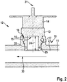
- Fig. 2 shows a schematic representation of the in Fig. 1 STB 12 shown and inserted into the fluid-permeable channel 11.
- the STB 12 is arranged in the coupling element receptacle 17 of the fluid-permeable channel 11.
- the STB 12 is arranged in a sealing manner on the fluid contact side with the coupling element 13 through the opening 18 in the coupling element receptacle 17.
- the sealing effect takes place on the one hand through a force-fitting and / or form-fitting arrangement of the coupling element 13 in the coupling element receptacle 17.
- the tapering design of the outer surface 19 of the coupling element 13 in conjunction with the corresponding geometry of the coupling element receptacle 17 leads to the coupling element 13 is set up to be arranged in a sealing seat in the coupling element receptacle 17.
- the sealing effect takes place in addition through at least one sealing means 22 which is arranged in the sealing means receptacle 20.
- the arrangement of the coupling element 13 in the coupling element receptacle 17 is preferably reversible.
- the sealing means 22 further preferably comprises a circumferential sealing means, for example an O-ring.
- the water heater according to the invention preferably comprises at least one clamp - not shown in the figures - for supporting fixation of the STB 12 in the coupling element receptacle 17.
- both the coupling element 13 and the coupling element receptacle 17 comprise corresponding clamp receptacles 26.
- the clip receptacles 26 are designed and set up to receive at least one clip.
- the coupling element 13 with the fluid contact side 15 is arranged in the coupling element receptacle 17 in such a way that it does not or only insignificantly influences the flow direction 30 of the liquid in the fluid-permeable channel 11.
- the coupling element 13 is arranged with the fluid contact side 15 in the coupling element receptacle 17 in such a way that it is oriented in the direction of the flow direction of the liquid 30. This has the effect that the coupling element 13 with the recess 16 forming the cavity is aligned against the direction of flow 30 of the liquid and that the liquid flows into the cavity. In this way, a particularly fast response behavior of the STB according to the invention is achieved.
- the coupling element 13 is arranged on the fluid contact side at least essentially flush with the inner surface 23 of the fluid-accessible channel 11.
- the coupling element 13 is arranged in such a way that it ends flush or essentially flush with the inner surface 23 of the fluid-accessible channel 11 on the fluid contact side.
- the Fig. 1 and Fig. 2 also show the depth 24 of the cavity-forming recess 16 of the coupling element 13.
- the depth 24 of the cavity-forming recess 16 extends over at least half the dimension of the coupling element receptacle 17, the dimension of the coupling element receptacle 17 in particular due to the smallest width of the opening 18 of the fluid-permeable Channel 11 is defined.
- the coupling element 13 has a circumferential wall 25 with a defined wall width which laterally surrounds the cavity.
- the wall width of the wall 25 is preferably designed to be at least 1 mm wide.
- the smallest wall width of the wall 25 is, for example, in the area of the sealant receptacle 20, the clamp receptacle 26 or in the area of the profiled surface 21.
- Fig. 3 shows a schematic representation of an STB 12 in a perspective view.
- the coupling element 13 of the STB 12 is designed to be rotationally symmetrical with respect to an axis 21.
- the areas of the outer surface 19, the sealant receptacle 20 and the profiled surface 21 of the coupling element 13 are also designed and configured to be rotationally symmetrical.
- the cross section of the elements is preferably circular.
- the rotationally symmetrical design of the coupling element 13 offers the advantage that the coupling element 13 can be machined by turning.
Landscapes
- Engineering & Computer Science (AREA)
- Physics & Mathematics (AREA)
- Thermal Sciences (AREA)
- Chemical & Material Sciences (AREA)
- Combustion & Propulsion (AREA)
- Mechanical Engineering (AREA)
- General Engineering & Computer Science (AREA)
- Instantaneous Water Boilers, Portable Hot-Water Supply Apparatuses, And Control Of Portable Hot-Water Supply Apparatuses (AREA)
Priority Applications (3)
| Application Number | Priority Date | Filing Date | Title |
|---|---|---|---|
| PL19160092T PL3702693T3 (pl) | 2019-02-28 | 2019-02-28 | Podgrzewacz przepływowy z zabezpieczającym ogranicznikiem temperatury ze stroną stykającą się z płynem |
| EP19160092.3A EP3702693B1 (de) | 2019-02-28 | 2019-02-28 | Durchlauferhitzer mit fluidkontaktseitigem sicherheitstemperaturbegrenzer |
| CN202010129120.7A CN111629461B (zh) | 2019-02-28 | 2020-02-28 | 流体接触侧的安全温度限制器 |
Applications Claiming Priority (1)
| Application Number | Priority Date | Filing Date | Title |
|---|---|---|---|
| EP19160092.3A EP3702693B1 (de) | 2019-02-28 | 2019-02-28 | Durchlauferhitzer mit fluidkontaktseitigem sicherheitstemperaturbegrenzer |
Publications (2)
| Publication Number | Publication Date |
|---|---|
| EP3702693A1 EP3702693A1 (de) | 2020-09-02 |
| EP3702693B1 true EP3702693B1 (de) | 2021-10-27 |
Family
ID=65657278
Family Applications (1)
| Application Number | Title | Priority Date | Filing Date |
|---|---|---|---|
| EP19160092.3A Active EP3702693B1 (de) | 2019-02-28 | 2019-02-28 | Durchlauferhitzer mit fluidkontaktseitigem sicherheitstemperaturbegrenzer |
Country Status (3)
| Country | Link |
|---|---|
| EP (1) | EP3702693B1 (pl) |
| CN (1) | CN111629461B (pl) |
| PL (1) | PL3702693T3 (pl) |
Family Cites Families (11)
| Publication number | Priority date | Publication date | Assignee | Title |
|---|---|---|---|---|
| DE2348570C3 (de) * | 1973-09-27 | 1982-11-04 | Behr-Thomson Dehnstoffregler Gmbh, 7014 Kornwestheim | Schaltgerät mit temperaturabhängigem Betätigungselement |
| DE2444931C3 (de) * | 1974-09-20 | 1981-07-23 | Behr-Thomson Dehnstoffregler Gmbh, 7014 Kornwestheim | Elektrisches Schaltgerät |
| DE2600599B2 (de) * | 1976-01-09 | 1978-01-26 | Behr-Thomson Dehnstoffregler Gmbh, 7014 Kornwestheim | Temperaturabhaengiges schaltgeraet |
| DE19854639C5 (de) * | 1998-11-26 | 2014-02-13 | BSH Bosch und Siemens Hausgeräte GmbH | Durchlauferhitzer mit einer Übertemperaturschutzeinrichtung |
| DE29825255U1 (de) | 1998-11-26 | 2007-03-08 | BSH Bosch und Siemens Hausgeräte GmbH | Durchlauferhitzer mit einer Übertemperaturschutzeinrichtung |
| US6839509B2 (en) * | 2003-02-28 | 2005-01-04 | Valeo Electrical Systems, Inc. | Fluid heater control apparatus and method with overtemperature protection |
| DE102007052934A1 (de) | 2007-11-02 | 2009-05-14 | Gerdes Ohg | Durchlauferhitzer mit einem Sicherheitstemperaturbegrenzer |
| US8081058B2 (en) * | 2008-06-10 | 2011-12-20 | Neilly William C | Thermally activated electrical interrupt switch |
| EP2489948A1 (de) * | 2011-02-21 | 2012-08-22 | Gerdes OHG | Blankdrahtdurchlauferhitzer zur Wassererwärmung |
| EP2489951B1 (de) * | 2011-02-21 | 2017-04-05 | Gerdes OHG | Elektrischer Durchlauferhitzer |
| JP6029850B2 (ja) * | 2012-05-10 | 2016-11-24 | サンデンホールディングス株式会社 | 加熱装置 |
-
2019
- 2019-02-28 PL PL19160092T patent/PL3702693T3/pl unknown
- 2019-02-28 EP EP19160092.3A patent/EP3702693B1/de active Active
-
2020
- 2020-02-28 CN CN202010129120.7A patent/CN111629461B/zh active Active
Also Published As
| Publication number | Publication date |
|---|---|
| EP3702693A1 (de) | 2020-09-02 |
| CN111629461A (zh) | 2020-09-04 |
| CN111629461B (zh) | 2024-03-12 |
| PL3702693T3 (pl) | 2022-02-21 |
Similar Documents
| Publication | Publication Date | Title |
|---|---|---|
| EP2693835B1 (de) | Heizeinrichtung und Elektrogerät mit Heizeinrichtung | |
| EP1715259B1 (de) | Beheizte Pumpe mit Kochschutz | |
| EP2295886B1 (de) | Vorrichtung zum Erwärmen von Flüssigkeiten | |
| EP2407069A1 (de) | Dynamischer Durchlauferhitzer | |
| CH647867A5 (en) | Temperature sensor | |
| DE102019214024A1 (de) | Kontaktstift mit Kühlkanalsystem und elektrischer Stecker mit einem solchen Kontaktstift | |
| DE102010006740B4 (de) | Messsonde | |
| EP3702693B1 (de) | Durchlauferhitzer mit fluidkontaktseitigem sicherheitstemperaturbegrenzer | |
| EP3705804B1 (de) | Haustechnikgerät und flanschverbindung für ein solches haustechnikgerät | |
| DE102011075123B4 (de) | Durchflussbegrenzungselement, Durchflussbegrenzungseinheit, Verfahren zur Durchflussbegrenzung, Heizkörper und Durchlauferhitzer | |
| DE3701240A1 (de) | Thermostat | |
| EP4025841B1 (de) | Niederhalter zum niederhalten eines messsensors und weiterleiten eines elektrischen messsignals | |
| DE102004062908A1 (de) | Sensor und Verfahren zum Herstellen eines Sensors | |
| WO2017149008A1 (de) | Heizpatrone mit einem schutzrohr | |
| DE69808374T2 (de) | Elektrischer Durchlaufwassererhitzer Anordnung insbesondere für Kaffee oder ähnliche Maschinen | |
| DE19934319A1 (de) | Heizvorrichtung mit Laugentemperaturregelung | |
| DE102013102925A1 (de) | Spritzgießdüse mit zweiteiligem Materialrohr | |
| DE202007017796U1 (de) | Sicherungsvorrichtung für einen Durchlauferhitzer | |
| EP0230496B1 (de) | Temperatur-Regeleinrichtung, insbesondere für Flüssigkeiten oder Gase | |
| DE19808655C2 (de) | Temperaturfühleranordnung insbesondere für Wärmezähler | |
| DE10119107B4 (de) | Elektrische Heizpatrone mit einem temperaturabhängigen Leistungsbegrenzer | |
| EP2868967A1 (de) | Verdampfer für eine Nebelmaschine | |
| DE102016221601B4 (de) | Thermostat für einen Getriebeölkreislauf und Getriebeölkreislauf | |
| DE10255522B4 (de) | Ventil mit Durchflussmesser | |
| EP2570881B2 (de) | Temperaturregelvorrichtung, insbesondere Thermostatvorrichtung |
Legal Events
| Date | Code | Title | Description |
|---|---|---|---|
| PUAI | Public reference made under article 153(3) epc to a published international application that has entered the european phase |
Free format text: ORIGINAL CODE: 0009012 |
|
| STAA | Information on the status of an ep patent application or granted ep patent |
Free format text: STATUS: THE APPLICATION HAS BEEN PUBLISHED |
|
| AK | Designated contracting states |
Kind code of ref document: A1 Designated state(s): AL AT BE BG CH CY CZ DE DK EE ES FI FR GB GR HR HU IE IS IT LI LT LU LV MC MK MT NL NO PL PT RO RS SE SI SK SM TR |
|
| AX | Request for extension of the european patent |
Extension state: BA ME |
|
| STAA | Information on the status of an ep patent application or granted ep patent |
Free format text: STATUS: REQUEST FOR EXAMINATION WAS MADE |
|
| 17P | Request for examination filed |
Effective date: 20210226 |
|
| RBV | Designated contracting states (corrected) |
Designated state(s): AL AT BE BG CH CY CZ DE DK EE ES FI FR GB GR HR HU IE IS IT LI LT LU LV MC MK MT NL NO PL PT RO RS SE SI SK SM TR |
|
| GRAP | Despatch of communication of intention to grant a patent |
Free format text: ORIGINAL CODE: EPIDOSNIGR1 |
|
| STAA | Information on the status of an ep patent application or granted ep patent |
Free format text: STATUS: GRANT OF PATENT IS INTENDED |
|
| RIC1 | Information provided on ipc code assigned before grant |
Ipc: F24H 9/20 20060101AFI20210423BHEP Ipc: H01H 37/00 20060101ALI20210423BHEP Ipc: H01H 37/04 20060101ALI20210423BHEP Ipc: F24H 1/10 20060101ALI20210423BHEP |
|
| INTG | Intention to grant announced |
Effective date: 20210521 |
|
| GRAS | Grant fee paid |
Free format text: ORIGINAL CODE: EPIDOSNIGR3 |
|
| GRAA | (expected) grant |
Free format text: ORIGINAL CODE: 0009210 |
|
| STAA | Information on the status of an ep patent application or granted ep patent |
Free format text: STATUS: THE PATENT HAS BEEN GRANTED |
|
| AK | Designated contracting states |
Kind code of ref document: B1 Designated state(s): AL AT BE BG CH CY CZ DE DK EE ES FI FR GB GR HR HU IE IS IT LI LT LU LV MC MK MT NL NO PL PT RO RS SE SI SK SM TR |
|
| REG | Reference to a national code |
Ref country code: GB Ref legal event code: FG4D Free format text: NOT ENGLISH |
|
| REG | Reference to a national code |
Ref country code: CH Ref legal event code: EP |
|
| REG | Reference to a national code |
Ref country code: DE Ref legal event code: R096 Ref document number: 502019002578 Country of ref document: DE |
|
| REG | Reference to a national code |
Ref country code: AT Ref legal event code: REF Ref document number: 1442132 Country of ref document: AT Kind code of ref document: T Effective date: 20211115 |
|
| REG | Reference to a national code |
Ref country code: IE Ref legal event code: FG4D Free format text: LANGUAGE OF EP DOCUMENT: GERMAN |
|
| REG | Reference to a national code |
Ref country code: LT Ref legal event code: MG9D |
|
| REG | Reference to a national code |
Ref country code: NL Ref legal event code: MP Effective date: 20211027 |
|
| PG25 | Lapsed in a contracting state [announced via postgrant information from national office to epo] |
Ref country code: RS Free format text: LAPSE BECAUSE OF FAILURE TO SUBMIT A TRANSLATION OF THE DESCRIPTION OR TO PAY THE FEE WITHIN THE PRESCRIBED TIME-LIMIT Effective date: 20211027 Ref country code: LT Free format text: LAPSE BECAUSE OF FAILURE TO SUBMIT A TRANSLATION OF THE DESCRIPTION OR TO PAY THE FEE WITHIN THE PRESCRIBED TIME-LIMIT Effective date: 20211027 Ref country code: FI Free format text: LAPSE BECAUSE OF FAILURE TO SUBMIT A TRANSLATION OF THE DESCRIPTION OR TO PAY THE FEE WITHIN THE PRESCRIBED TIME-LIMIT Effective date: 20211027 Ref country code: BG Free format text: LAPSE BECAUSE OF FAILURE TO SUBMIT A TRANSLATION OF THE DESCRIPTION OR TO PAY THE FEE WITHIN THE PRESCRIBED TIME-LIMIT Effective date: 20220127 |
|
| PG25 | Lapsed in a contracting state [announced via postgrant information from national office to epo] |
Ref country code: IS Free format text: LAPSE BECAUSE OF FAILURE TO SUBMIT A TRANSLATION OF THE DESCRIPTION OR TO PAY THE FEE WITHIN THE PRESCRIBED TIME-LIMIT Effective date: 20220227 Ref country code: SE Free format text: LAPSE BECAUSE OF FAILURE TO SUBMIT A TRANSLATION OF THE DESCRIPTION OR TO PAY THE FEE WITHIN THE PRESCRIBED TIME-LIMIT Effective date: 20211027 Ref country code: PT Free format text: LAPSE BECAUSE OF FAILURE TO SUBMIT A TRANSLATION OF THE DESCRIPTION OR TO PAY THE FEE WITHIN THE PRESCRIBED TIME-LIMIT Effective date: 20220228 Ref country code: NO Free format text: LAPSE BECAUSE OF FAILURE TO SUBMIT A TRANSLATION OF THE DESCRIPTION OR TO PAY THE FEE WITHIN THE PRESCRIBED TIME-LIMIT Effective date: 20220127 Ref country code: NL Free format text: LAPSE BECAUSE OF FAILURE TO SUBMIT A TRANSLATION OF THE DESCRIPTION OR TO PAY THE FEE WITHIN THE PRESCRIBED TIME-LIMIT Effective date: 20211027 Ref country code: LV Free format text: LAPSE BECAUSE OF FAILURE TO SUBMIT A TRANSLATION OF THE DESCRIPTION OR TO PAY THE FEE WITHIN THE PRESCRIBED TIME-LIMIT Effective date: 20211027 Ref country code: HR Free format text: LAPSE BECAUSE OF FAILURE TO SUBMIT A TRANSLATION OF THE DESCRIPTION OR TO PAY THE FEE WITHIN THE PRESCRIBED TIME-LIMIT Effective date: 20211027 Ref country code: GR Free format text: LAPSE BECAUSE OF FAILURE TO SUBMIT A TRANSLATION OF THE DESCRIPTION OR TO PAY THE FEE WITHIN THE PRESCRIBED TIME-LIMIT Effective date: 20220128 Ref country code: ES Free format text: LAPSE BECAUSE OF FAILURE TO SUBMIT A TRANSLATION OF THE DESCRIPTION OR TO PAY THE FEE WITHIN THE PRESCRIBED TIME-LIMIT Effective date: 20211027 |
|
| REG | Reference to a national code |
Ref country code: DE Ref legal event code: R097 Ref document number: 502019002578 Country of ref document: DE |
|
| PG25 | Lapsed in a contracting state [announced via postgrant information from national office to epo] |
Ref country code: SM Free format text: LAPSE BECAUSE OF FAILURE TO SUBMIT A TRANSLATION OF THE DESCRIPTION OR TO PAY THE FEE WITHIN THE PRESCRIBED TIME-LIMIT Effective date: 20211027 Ref country code: SK Free format text: LAPSE BECAUSE OF FAILURE TO SUBMIT A TRANSLATION OF THE DESCRIPTION OR TO PAY THE FEE WITHIN THE PRESCRIBED TIME-LIMIT Effective date: 20211027 Ref country code: RO Free format text: LAPSE BECAUSE OF FAILURE TO SUBMIT A TRANSLATION OF THE DESCRIPTION OR TO PAY THE FEE WITHIN THE PRESCRIBED TIME-LIMIT Effective date: 20211027 Ref country code: EE Free format text: LAPSE BECAUSE OF FAILURE TO SUBMIT A TRANSLATION OF THE DESCRIPTION OR TO PAY THE FEE WITHIN THE PRESCRIBED TIME-LIMIT Effective date: 20211027 Ref country code: DK Free format text: LAPSE BECAUSE OF FAILURE TO SUBMIT A TRANSLATION OF THE DESCRIPTION OR TO PAY THE FEE WITHIN THE PRESCRIBED TIME-LIMIT Effective date: 20211027 Ref country code: CZ Free format text: LAPSE BECAUSE OF FAILURE TO SUBMIT A TRANSLATION OF THE DESCRIPTION OR TO PAY THE FEE WITHIN THE PRESCRIBED TIME-LIMIT Effective date: 20211027 |
|
| PLBE | No opposition filed within time limit |
Free format text: ORIGINAL CODE: 0009261 |
|
| STAA | Information on the status of an ep patent application or granted ep patent |
Free format text: STATUS: NO OPPOSITION FILED WITHIN TIME LIMIT |
|
| PG25 | Lapsed in a contracting state [announced via postgrant information from national office to epo] |
Ref country code: MC Free format text: LAPSE BECAUSE OF FAILURE TO SUBMIT A TRANSLATION OF THE DESCRIPTION OR TO PAY THE FEE WITHIN THE PRESCRIBED TIME-LIMIT Effective date: 20211027 |
|
| 26N | No opposition filed |
Effective date: 20220728 |
|
| REG | Reference to a national code |
Ref country code: CH Ref legal event code: PL |
|
| REG | Reference to a national code |
Ref country code: BE Ref legal event code: MM Effective date: 20220228 |
|
| PG25 | Lapsed in a contracting state [announced via postgrant information from national office to epo] |
Ref country code: LU Free format text: LAPSE BECAUSE OF NON-PAYMENT OF DUE FEES Effective date: 20220228 Ref country code: AL Free format text: LAPSE BECAUSE OF FAILURE TO SUBMIT A TRANSLATION OF THE DESCRIPTION OR TO PAY THE FEE WITHIN THE PRESCRIBED TIME-LIMIT Effective date: 20211027 |
|
| PG25 | Lapsed in a contracting state [announced via postgrant information from national office to epo] |
Ref country code: SI Free format text: LAPSE BECAUSE OF FAILURE TO SUBMIT A TRANSLATION OF THE DESCRIPTION OR TO PAY THE FEE WITHIN THE PRESCRIBED TIME-LIMIT Effective date: 20211027 |
|
| PG25 | Lapsed in a contracting state [announced via postgrant information from national office to epo] |
Ref country code: LI Free format text: LAPSE BECAUSE OF NON-PAYMENT OF DUE FEES Effective date: 20220228 Ref country code: IE Free format text: LAPSE BECAUSE OF NON-PAYMENT OF DUE FEES Effective date: 20220228 Ref country code: CH Free format text: LAPSE BECAUSE OF NON-PAYMENT OF DUE FEES Effective date: 20220228 |
|
| PGRI | Patent reinstated in contracting state [announced from national office to epo] |
Ref country code: LI Effective date: 20221114 Ref country code: CH Effective date: 20221114 |
|
| PG25 | Lapsed in a contracting state [announced via postgrant information from national office to epo] |
Ref country code: BE Free format text: LAPSE BECAUSE OF NON-PAYMENT OF DUE FEES Effective date: 20220228 |
|
| P01 | Opt-out of the competence of the unified patent court (upc) registered |
Effective date: 20230512 |
|
| PG25 | Lapsed in a contracting state [announced via postgrant information from national office to epo] |
Ref country code: MK Free format text: LAPSE BECAUSE OF FAILURE TO SUBMIT A TRANSLATION OF THE DESCRIPTION OR TO PAY THE FEE WITHIN THE PRESCRIBED TIME-LIMIT Effective date: 20211027 Ref country code: CY Free format text: LAPSE BECAUSE OF FAILURE TO SUBMIT A TRANSLATION OF THE DESCRIPTION OR TO PAY THE FEE WITHIN THE PRESCRIBED TIME-LIMIT Effective date: 20211027 |
|
| PG25 | Lapsed in a contracting state [announced via postgrant information from national office to epo] |
Ref country code: HU Free format text: LAPSE BECAUSE OF FAILURE TO SUBMIT A TRANSLATION OF THE DESCRIPTION OR TO PAY THE FEE WITHIN THE PRESCRIBED TIME-LIMIT; INVALID AB INITIO Effective date: 20190228 |
|
| PG25 | Lapsed in a contracting state [announced via postgrant information from national office to epo] |
Ref country code: TR Free format text: LAPSE BECAUSE OF FAILURE TO SUBMIT A TRANSLATION OF THE DESCRIPTION OR TO PAY THE FEE WITHIN THE PRESCRIBED TIME-LIMIT Effective date: 20211027 |
|
| PG25 | Lapsed in a contracting state [announced via postgrant information from national office to epo] |
Ref country code: MT Free format text: LAPSE BECAUSE OF FAILURE TO SUBMIT A TRANSLATION OF THE DESCRIPTION OR TO PAY THE FEE WITHIN THE PRESCRIBED TIME-LIMIT Effective date: 20211027 |
|
| PGFP | Annual fee paid to national office [announced via postgrant information from national office to epo] |
Ref country code: DE Payment date: 20250108 Year of fee payment: 7 |
|
| PGFP | Annual fee paid to national office [announced via postgrant information from national office to epo] |
Ref country code: CH Payment date: 20250301 Year of fee payment: 7 Ref country code: AT Payment date: 20250217 Year of fee payment: 7 |
|
| PGFP | Annual fee paid to national office [announced via postgrant information from national office to epo] |
Ref country code: PL Payment date: 20250108 Year of fee payment: 7 Ref country code: FR Payment date: 20250219 Year of fee payment: 7 |
|
| PGFP | Annual fee paid to national office [announced via postgrant information from national office to epo] |
Ref country code: GB Payment date: 20250108 Year of fee payment: 7 Ref country code: IT Payment date: 20250228 Year of fee payment: 7 |
|
| REG | Reference to a national code |
Ref country code: CH Ref legal event code: U11 Free format text: ST27 STATUS EVENT CODE: U-0-0-U10-U11 (AS PROVIDED BY THE NATIONAL OFFICE) Effective date: 20260301 |