EP3702693B1 - Durchlauferhitzer mit fluidkontaktseitigem sicherheitstemperaturbegrenzer - Google Patents
Durchlauferhitzer mit fluidkontaktseitigem sicherheitstemperaturbegrenzer Download PDFInfo
- Publication number
- EP3702693B1 EP3702693B1 EP19160092.3A EP19160092A EP3702693B1 EP 3702693 B1 EP3702693 B1 EP 3702693B1 EP 19160092 A EP19160092 A EP 19160092A EP 3702693 B1 EP3702693 B1 EP 3702693B1
- Authority
- EP
- European Patent Office
- Prior art keywords
- coupling element
- continuous
- fluid
- flow heater
- heater according
- Prior art date
- Legal status (The legal status is an assumption and is not a legal conclusion. Google has not performed a legal analysis and makes no representation as to the accuracy of the status listed.)
- Active
Links
- 239000012530 fluid Substances 0.000 title claims description 49
- 230000008878 coupling Effects 0.000 claims description 137
- 238000010168 coupling process Methods 0.000 claims description 137
- 238000005859 coupling reaction Methods 0.000 claims description 137
- 238000010438 heat treatment Methods 0.000 claims description 54
- 239000007788 liquid Substances 0.000 claims description 39
- 238000012546 transfer Methods 0.000 claims description 10
- 239000000565 sealant Substances 0.000 claims description 8
- 229910052751 metal Inorganic materials 0.000 claims description 7
- 239000002184 metal Substances 0.000 claims description 7
- 239000000463 material Substances 0.000 claims description 5
- 239000003651 drinking water Substances 0.000 claims description 3
- 235000020188 drinking water Nutrition 0.000 claims description 3
- 229910001369 Brass Inorganic materials 0.000 claims description 2
- 239000010951 brass Substances 0.000 claims description 2
- XLYOFNOQVPJJNP-UHFFFAOYSA-N water Substances O XLYOFNOQVPJJNP-UHFFFAOYSA-N 0.000 description 32
- 238000007789 sealing Methods 0.000 description 10
- 238000013461 design Methods 0.000 description 5
- 238000011161 development Methods 0.000 description 4
- 230000000694 effects Effects 0.000 description 4
- 230000003111 delayed effect Effects 0.000 description 3
- 230000001419 dependent effect Effects 0.000 description 3
- 238000004519 manufacturing process Methods 0.000 description 3
- 239000007787 solid Substances 0.000 description 3
- 230000015572 biosynthetic process Effects 0.000 description 2
- 230000007797 corrosion Effects 0.000 description 2
- 238000005260 corrosion Methods 0.000 description 2
- 238000000034 method Methods 0.000 description 2
- 230000008092 positive effect Effects 0.000 description 2
- 230000002441 reversible effect Effects 0.000 description 2
- 239000010935 stainless steel Substances 0.000 description 2
- 229910001220 stainless steel Inorganic materials 0.000 description 2
- RYGMFSIKBFXOCR-UHFFFAOYSA-N Copper Chemical compound [Cu] RYGMFSIKBFXOCR-UHFFFAOYSA-N 0.000 description 1
- 229910045601 alloy Inorganic materials 0.000 description 1
- 239000000956 alloy Substances 0.000 description 1
- 229910052782 aluminium Inorganic materials 0.000 description 1
- XAGFODPZIPBFFR-UHFFFAOYSA-N aluminium Chemical compound [Al] XAGFODPZIPBFFR-UHFFFAOYSA-N 0.000 description 1
- 230000009286 beneficial effect Effects 0.000 description 1
- 238000009529 body temperature measurement Methods 0.000 description 1
- 230000001276 controlling effect Effects 0.000 description 1
- 229910052802 copper Inorganic materials 0.000 description 1
- 239000010949 copper Substances 0.000 description 1
- 230000001066 destructive effect Effects 0.000 description 1
- 238000005553 drilling Methods 0.000 description 1
- PCHJSUWPFVWCPO-UHFFFAOYSA-N gold Chemical compound [Au] PCHJSUWPFVWCPO-UHFFFAOYSA-N 0.000 description 1
- 229910052737 gold Inorganic materials 0.000 description 1
- 239000010931 gold Substances 0.000 description 1
- 238000009434 installation Methods 0.000 description 1
- 238000009413 insulation Methods 0.000 description 1
- 230000007774 longterm Effects 0.000 description 1
- 230000007257 malfunction Effects 0.000 description 1
- 150000002739 metals Chemical class 0.000 description 1
- 238000003801 milling Methods 0.000 description 1
- 238000013021 overheating Methods 0.000 description 1
- 230000002028 premature Effects 0.000 description 1
- 230000001681 protective effect Effects 0.000 description 1
- 230000001105 regulatory effect Effects 0.000 description 1
- 229910052709 silver Inorganic materials 0.000 description 1
- 239000004332 silver Substances 0.000 description 1
- 239000000126 substance Substances 0.000 description 1
Images


Classifications
-
- F—MECHANICAL ENGINEERING; LIGHTING; HEATING; WEAPONS; BLASTING
- F24—HEATING; RANGES; VENTILATING
- F24H—FLUID HEATERS, e.g. WATER OR AIR HEATERS, HAVING HEAT-GENERATING MEANS, e.g. HEAT PUMPS, IN GENERAL
- F24H9/00—Details
- F24H9/20—Arrangement or mounting of control or safety devices
- F24H9/2007—Arrangement or mounting of control or safety devices for water heaters
- F24H9/2014—Arrangement or mounting of control or safety devices for water heaters using electrical energy supply
- F24H9/2028—Continuous-flow heaters
-
- H—ELECTRICITY
- H05—ELECTRIC TECHNIQUES NOT OTHERWISE PROVIDED FOR
- H05B—ELECTRIC HEATING; ELECTRIC LIGHT SOURCES NOT OTHERWISE PROVIDED FOR; CIRCUIT ARRANGEMENTS FOR ELECTRIC LIGHT SOURCES, IN GENERAL
- H05B3/00—Ohmic-resistance heating
- H05B3/40—Heating elements having the shape of rods or tubes
- H05B3/42—Heating elements having the shape of rods or tubes non-flexible
-
- F—MECHANICAL ENGINEERING; LIGHTING; HEATING; WEAPONS; BLASTING
- F24—HEATING; RANGES; VENTILATING
- F24H—FLUID HEATERS, e.g. WATER OR AIR HEATERS, HAVING HEAT-GENERATING MEANS, e.g. HEAT PUMPS, IN GENERAL
- F24H1/00—Water heaters, e.g. boilers, continuous-flow heaters or water-storage heaters
- F24H1/10—Continuous-flow heaters, i.e. heaters in which heat is generated only while the water is flowing, e.g. with direct contact of the water with the heating medium
- F24H1/101—Continuous-flow heaters, i.e. heaters in which heat is generated only while the water is flowing, e.g. with direct contact of the water with the heating medium using electric energy supply
-
- H—ELECTRICITY
- H05—ELECTRIC TECHNIQUES NOT OTHERWISE PROVIDED FOR
- H05B—ELECTRIC HEATING; ELECTRIC LIGHT SOURCES NOT OTHERWISE PROVIDED FOR; CIRCUIT ARRANGEMENTS FOR ELECTRIC LIGHT SOURCES, IN GENERAL
- H05B3/00—Ohmic-resistance heating
- H05B3/02—Details
- H05B3/06—Heater elements structurally combined with coupling elements or holders
- H05B3/08—Heater elements structurally combined with coupling elements or holders having electric connections specially adapted for high temperatures
-
- H—ELECTRICITY
- H01—ELECTRIC ELEMENTS
- H01H—ELECTRIC SWITCHES; RELAYS; SELECTORS; EMERGENCY PROTECTIVE DEVICES
- H01H37/00—Thermally-actuated switches
- H01H37/02—Details
- H01H37/04—Bases; Housings; Mountings
- H01H37/043—Mountings on controlled apparatus
Definitions
- the present invention relates to a flow heater for heating a liquid, comprising a heating cartridge with at least one fluid-permeable channel, at least one electrically heated heating element set up for heating the liquid being arranged in the fluid-permeable channel, and at least one safety temperature limiter which is set up when a predetermined maximum temperature of the liquid, the at least one heating element to be de-energized by means of a temperature-controlled switching element, the safety temperature limiter comprising a coupling element with a fluid contact side set up for heat transfer from the liquid to the switching element, the coupling element being arranged in such a way as to at least partially connect with the liquid To get in touch.
- Such instantaneous water heaters are sufficiently known from the prior art.
- the water to be heated is passed through a heating cartridge with at least one fluid-permeable channel.
- a heating device which is heated by means of electrical current and is thus used to heat the liquid.
- an automatic shutdown device which is regularly referred to as a safety temperature limiter, or "STB" for short.
- STB are usually designed in such a way that when a defined actual temperature or maximum temperature of the liquid inside the heating cartridge is exceeded, they automatically switch off the instantaneous water heater or the heating element located therein, i.e. either the continuous flow heater or the heating element located therein de-energize.
- An automatic shutdown comes into consideration above all, if there is a technical fault in the heating device or in the switching device for controlling / regulating the heating device, or if the flow of liquid is disturbed or interrupted. As a result, the maximum permissible temperature of the heating device and / or areas of the heating cartridge can be exceeded, which can damage the components mentioned.
- the triggering of the conventional STB often requires a certain period of time, since - depending on the arrangement of the STB in the water heater - triggering can only take place when the defined actual temperature or maximum temperature prevails at the place provided on the corresponding STB.
- the use of the STB should ideally contribute to the fact that the technical error that has occurred in the instantaneous water heater can be eliminated and that the instantaneous water heater can be used as intended for heating a liquid, eliminating the source of the error and / or malfunction without causing irreparable damage to the device .
- the heat transfer between the coupling element and the switching element is already known from the conventional STB.
- temperature-controlled switching elements such as bi-metal switches are already sufficiently known from the prior art.
- thermally activatable electrical interruption switch for displaying the release state is known, which is used, for example, in pumps.
- the DE 24 44 931 A1 discloses a switching device with a temperature-dependent linear servomotor.
- a recess is provided for receiving a substance that expands when heated.
- a switching device with a temperature-dependent actuating element is known.
- the switching device or parts thereof are intended to be arranged in an opening in a wall.
- the overtemperature protection device arranged directly inside the water duct section is also attached in the immediate vicinity of the heating element. This can lead to unwanted shutdowns of the instantaneous water heater if, for example, there is insufficient flow within the water channel section and local overheating occurs in the area of the STB. Furthermore, in the spatial proximity between the heating element and the excess temperature protection device, there is a risk of not measuring the actual temperature of the flowing liquid, but of indirectly detecting the higher temperature level of the bare wire heating coil. In this way, the temperature actually decisive for a shutdown is only recorded imprecisely, which can result in both a premature and a delayed shutdown of the instantaneous water heater or the heating device.
- the DE 298 25 255 U1 propose to arrange preferably two temperature sensors within the water channel section and to implement the STB function on the basis of two recorded temperatures. Furthermore, from the DE 10 2007 052 934 A1 a water heater is known in which a temperature transmitter for determining the water temperature within a flow channel is arranged completely outside of the flow channel. The temperature transmitter is not in direct contact with the liquid to be heated. This is intended to simplify and more reliably determine the temperature of the liquid to be heated, for example by reducing the corrosion of the temperature transmitter. Such an arrangement of a temperature transmitter has the disadvantage, however, that the temperature measurement for determining a maximum temperature and a shutdown of the flow heater resulting therefrom does not take place with the required speed.
- the flow channel In addition to its thermal resistance, the flow channel itself has a specific heat capacity, which leads to a correspondingly delayed registration of the maximum temperature that actually occurs. Delayed shutdown by the STB can lead to irreparable damage to the instantaneous water heater. In addition, if the temperature transmitter is positioned on the outside, an additional fastening must be provided for it, which is associated with higher production costs.
- the present invention is therefore based on the object of proposing an instantaneous water heater which is equipped with a safety temperature limiter which, on the one hand, ensures a reliable safety shutdown when a maximum temperature is exceeded and, on the other hand, reacts as quickly as possible.
- the coupling element has at least one recess forming a cavity on the fluid contact side.
- the recess of the coupling element which is arranged on the fluid contact side and forms a cavity, makes it possible to carry out rapid heat transfer between the coupling element and the temperature-controlled switching element.
- the cavity offers a large inner surface for rinsing with the liquid, which means that heat is absorbed more quickly. In other words, the cavity forms the largest possible thermal coupling surface.
- the specific heat capacity of the coupling element is significantly reduced compared to a solid body due to the material recess by means of the cavity. In this way, changes in temperature are transmitted through the coupling element much faster, since the inherent heat capacity of the coupling element is lower.
- the clearance between the coupling element and the switching element is reduced by the recess forming the cavity. The absorbed heat can thus be transferred more quickly to the switching element, as a result of which it disconnects the water heater from the voltage more quickly if necessary, ie when the maximum temperature is exceeded.
- the cavity of the recess can be designed in many ways, for example have different geometries, diameters or depths. The invention also offers a reliable shutdown with only a single coupling element for heat transfer, without further electronic components.
- the fluid contact side of the coupling element is arranged in such a way as to come into contact with the liquid at least in some areas. This takes place in that the coupling element is arranged on the fluid-permeable channel in order to form a closed fluid space with it.
- the coupling element is preferably inserted into an opening provided in the fluid-permeable channel, as a result of which a closed fluid space is created.
- the coupling element comprises a side facing away from the fluid, which has no contact area with the liquid of the fluid-permeable channel.
- the heating cartridge preferably consists of several fluid-accessible channels, an electrically heated heating element being arranged in at least one of the fluid-accessible channels.
- An electrically heated heating element does not preferably have to be arranged in each of the fluid-accessible channels.
- the electrically heated heating element set up to heat the liquid can also only be arranged in a partial area of the fluid-accessible channel for heating the liquid, or alternatively one or more electrically heated heating elements can be arranged in each of the fluid-accessible channels.
- a further expedient embodiment of the invention is characterized in that the heating cartridge comprises a plurality of the fluid-permeable channels arranged in series and the coupling element is arranged in the last of the fluid-permeable channels on the outlet side with respect to the flow direction.
- the positioning of the coupling element in the last channel on the outlet side has the advantage that the fluid regularly has the highest temperature here, which leads to a reliable shutdown of the flow heater when the specified maximum temperature is reached. This also ensures that the highest temperature occurring in the heating cartridge is always recorded.
- the coupling element can be arranged in a different position in one of the fluid-accessible heating channels.
- the fluid alternatively also referred to as liquid, in the context of the invention is preferably to be understood as drinking water or service water or any other fluid that is provided for heating in a domestic or commercial environment.
- the direction of flow depends on how the heating cartridge or the fluid-permeable channels are designed and set up and in which position the instantaneous water heater is installed when used as intended.
- a preferred development of the invention is characterized in that the coupling element comprises a thermally conductive metal, in particular is made of brass.
- the coupling element is preferably made solid and in one piece.
- the coupling element can consist of other thermally conductive metals, in particular aluminum, copper, stainless steel (e.g. stainless steel with the technical designation V2A or V4A), silver, gold or an alloy comprising at least one thermally conductive metal.
- the coupling element consists of a multi-component material, comprising at least one thermally conductive metal.
- the cavity-forming recess of the coupling element is at least essentially cylindrical.
- This offers the advantage that the cavity can be created using simple and inexpensive production techniques.
- the cylindrical cavity has a positive effect in terms of flow, as it is flowed around continuously and without any noteworthy vortex formation.
- the coupling element has no negative effects on the flow resistance.
- the cylindrical recess is preferably produced in a solid body by means of a drilling or milling process.
- the region of the cavity of the recess which faces opposite the opening of the cavity and thus into the side facing away from the fluid is at least substantially partially spherical. As a result, the flow behavior of the fluid in this area is further improved and a constant exchange of the fluid in the local area around the coupling element takes place even if the fluid flow speeds are low.
- a preferred development of the invention is characterized in that the cavity-forming recess of the coupling element is at least substantially cuboid.
- the cuboid cavity of the recess can have a positive effect on the heat transfer behavior between the coupling element and the switching element in certain designs of the fluid-permeable channel.
- the geometry of the recess favors that, depending on the design of the heating cartridge and the arrangement of the coupling element in the heating cartridge, the recess is reliably rinsed with the fluid.
- Another expedient embodiment of the invention is characterized in that the switching element is arranged in contact with the coupling element on the side facing away from the fluid.
- the heat that is absorbed by the inner surfaces of the cavity-forming recess of the coupling element is transferred to the switching element over the shortest possible path, so that when the predetermined maximum temperature is reached, the circuit of the water heater is disconnected from the voltage virtually without delay.
- the side of the coupling element facing away from the fluid is not in direct contact with the fluid, as a result of which the switching element can consist of cheaper materials that do not necessarily have to be corrosion-resistant.
- Another preferred embodiment of the invention is characterized in that the coupling element arranged in the heating cartridge is arranged in a coupling element receptacle of the fluid-permeable channel, in particular in a force-fitting and / or form-fitting manner.
- This offers the advantage that the coupling element is arranged secured against pressure and impact forces.
- the arrangement of the coupling element in the coupling element receptacle is preferably designed to be reversible, so that the STB according to the invention is designed to be exchangeable
- Another expedient embodiment of the invention is characterized in that the recess forming the cavity in the coupling element extends in depth over at least half the dimension of the coupling element receptacle. In this way it is ensured that the coupling element has a corresponding structural strength, so that on the one hand it withstands the fluid under pre-pressure and on the other hand has the lowest possible intrinsic heat capacity.
- the coupling element has an outer surface which has at least one thread, a profiled surface and / or at least one circumferential sealant receptacle. In this way it is ensured that the coupling element can be installed with little manufacturing effort and, if necessary, can be removed again in a non-destructive manner.
- the sealant receptacle By means of the sealant receptacle, the coupling element is set up to be arranged in the fluid-permeable channel in a tight and sealing seat.
- Another advantageous embodiment of the invention is characterized in that at least one sealing means, preferably in the form of an O-ring, is arranged on the outer surface of the coupling element and / or the coupling element receptacle. This ensures a reliable seal between the coupling element and the switching element and thus reliably separates fluid-carrying areas from the electrical, voltage-carrying areas
- an advantageous development of the invention is characterized in that the coupling element is arranged at least substantially orthogonally to the wall of the fluid-permeable channel or inclined against the flow direction on the fluid contact side in the coupling element receptacle.
- the fluid always rinsing around the cavity, even with different positions of the coupling element in the fluid-permeable channel and with different flow rates and flow rates in the fluid-permeable channel.
- installation will take place at least substantially orthogonally to the direction of extent of the fluid-permeable channel, with "at least substantially orthogonal” in the sense of the invention meaning either orthogonal or almost orthogonal, i.e. H. with a deviation from the orthogonal by a maximum of ⁇ 10 °.
- the coupling element is arranged on the fluid contact side at least essentially flush with the inner surface of the fluid-accessible channel. This offers the advantage that no undesired turbulence of the fluid occurs within the fluid-permeable channel when it flows through the coupling element.
- the coupling element is intended to form a surface free of bumps with the inner surface. "At least essentially flush" in the context of the invention means either flush or almost flush with the inner surface, i.e. H. with a deviation of a few mm.
- Another expedient embodiment of the invention is characterized in that the coupling element is arranged on the fluid contact side at least partially protruding into the fluid-accessible channel.
- the coupling element is arranged on the fluid contact side at least partially protruding into the fluid-accessible channel.
- the coupling element is arranged, on the fluid contact side, at least partially so as to protrude counter to the flow direction into the fluid-permeable channel.
- Another expedient embodiment of the invention is characterized in that the smallest thickness of the wall of the recess forming the cavity is at least 1 mm. In this way, reliable and long-term use can take place when pressures and temperature fluctuations occur within the heating cartridge. More preferably, the smallest thickness of the wall of the recess forming the cavity is in the range between 2 and 4 mm.
- Another advantageous embodiment of the invention is characterized in that the coupling element consists of a material suitable for drinking water.
- the instantaneous water heater according to the invention - not shown in the drawings - for heating a liquid will first be described below with reference to FIG Fig. 1 are explained in more detail.
- the instantaneous water heater comprises a heating cartridge 10 with at least one fluid-permeable channel 11, with at least one electrically heated heating element (not shown in the drawing) being arranged in the fluid-permeable channel 11.
- the instantaneous water heater also includes at least one safety temperature limiter 12, "STB” for short, which is set up to disconnect the at least one heating element from the voltage when a predetermined maximum temperature of the liquid is exceeded.
- STB safety temperature limiter
- the STB 12 comprises a coupling element 13 and a temperature-controlled switching element 14.
- the coupling element 13 is designed and set up for the transfer of heat from the liquid to the switching element 14. The actual switching process of disconnecting the water heater from voltage or switching off the at least one heating element takes place through the switching element 14.
- the coupling element 13 has a region facing away from the fluid and a region on the fluid contact side.
- the area facing away from the fluid does not come into contact with the liquid, while the area of the coupling element 13 on the fluid contact side comes into contact with the liquid at least in some areas.
- the switching element 14 is arranged in the area of the coupling element 13 facing away from the fluid.
- the coupling element 13 also has a fluid contact side 15 on the fluid contact side, which is designed to come into contact with the liquid at least in some areas.
- the coupling element 13 has on the fluid contact side at least one recess 16 which forms a cavity. In other words, the recess 16 forms a type of cavity in the coupling element 13 which is filled with the liquid.
- Both the coupling element 13 and the recess 16 forming a cavity are preferably cylindrical, as is the case, for example Fig. 3 can be found.
- the coupling element 13 can be due to the cylindrical design insert into circular recesses and thus arrange them in the fluid-permeable channel 11.
- Such STB 12 are preferably arranged in the flow direction or flow direction of the liquid 30 in the last of the fluid-accessible channels 11 on the outlet side.
- the instantaneous water heater according to the invention further comprises at least one coupling element receptacle 17 in the fluid-permeable channel 11.
- the coupling element receptacle 17 is arranged in the area of the fluid-permeable channel 11 and comprises an opening 18 through which the interior of the fluid-permeable channel 11 is accessible for the coupling element 13.
- the STB 12 according to the invention is preferably arranged on the fluid-accessible channel 11 via this coupling element receptacle 17 and at least the area of the STB 12 on the fluid contact side is hydraulically connected to the interior of the fluid-accessible channel 11.
- the geometry and size of the coupling element receptacle 17 are selected such that they correspond to the geometry and size of the coupling element 13 and the coupling element 13 can thus be arranged through the opening 18 in the coupling element receptacle 17.
- the coupling element 13 also has an outer surface 19.
- This outer surface 19 comprises, for example, a circumferential sealant receptacle 20 and a profiled surface 21.
- the outer surface 19 of the coupling element 13 with the circumferential sealant receptacle 20 and the profiled surface 21 is at least partially tapered towards the coupling element receptacle 17.
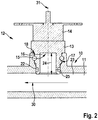
- Fig. 2 shows a schematic representation of the in Fig. 1 STB 12 shown and inserted into the fluid-permeable channel 11.
- the STB 12 is arranged in the coupling element receptacle 17 of the fluid-permeable channel 11.
- the STB 12 is arranged in a sealing manner on the fluid contact side with the coupling element 13 through the opening 18 in the coupling element receptacle 17.
- the sealing effect takes place on the one hand through a force-fitting and / or form-fitting arrangement of the coupling element 13 in the coupling element receptacle 17.
- the tapering design of the outer surface 19 of the coupling element 13 in conjunction with the corresponding geometry of the coupling element receptacle 17 leads to the coupling element 13 is set up to be arranged in a sealing seat in the coupling element receptacle 17.
- the sealing effect takes place in addition through at least one sealing means 22 which is arranged in the sealing means receptacle 20.
- the arrangement of the coupling element 13 in the coupling element receptacle 17 is preferably reversible.
- the sealing means 22 further preferably comprises a circumferential sealing means, for example an O-ring.
- the water heater according to the invention preferably comprises at least one clamp - not shown in the figures - for supporting fixation of the STB 12 in the coupling element receptacle 17.
- both the coupling element 13 and the coupling element receptacle 17 comprise corresponding clamp receptacles 26.
- the clip receptacles 26 are designed and set up to receive at least one clip.
- the coupling element 13 with the fluid contact side 15 is arranged in the coupling element receptacle 17 in such a way that it does not or only insignificantly influences the flow direction 30 of the liquid in the fluid-permeable channel 11.
- the coupling element 13 is arranged with the fluid contact side 15 in the coupling element receptacle 17 in such a way that it is oriented in the direction of the flow direction of the liquid 30. This has the effect that the coupling element 13 with the recess 16 forming the cavity is aligned against the direction of flow 30 of the liquid and that the liquid flows into the cavity. In this way, a particularly fast response behavior of the STB according to the invention is achieved.
- the coupling element 13 is arranged on the fluid contact side at least essentially flush with the inner surface 23 of the fluid-accessible channel 11.
- the coupling element 13 is arranged in such a way that it ends flush or essentially flush with the inner surface 23 of the fluid-accessible channel 11 on the fluid contact side.
- the Fig. 1 and Fig. 2 also show the depth 24 of the cavity-forming recess 16 of the coupling element 13.
- the depth 24 of the cavity-forming recess 16 extends over at least half the dimension of the coupling element receptacle 17, the dimension of the coupling element receptacle 17 in particular due to the smallest width of the opening 18 of the fluid-permeable Channel 11 is defined.
- the coupling element 13 has a circumferential wall 25 with a defined wall width which laterally surrounds the cavity.
- the wall width of the wall 25 is preferably designed to be at least 1 mm wide.
- the smallest wall width of the wall 25 is, for example, in the area of the sealant receptacle 20, the clamp receptacle 26 or in the area of the profiled surface 21.
- Fig. 3 shows a schematic representation of an STB 12 in a perspective view.
- the coupling element 13 of the STB 12 is designed to be rotationally symmetrical with respect to an axis 21.
- the areas of the outer surface 19, the sealant receptacle 20 and the profiled surface 21 of the coupling element 13 are also designed and configured to be rotationally symmetrical.
- the cross section of the elements is preferably circular.
- the rotationally symmetrical design of the coupling element 13 offers the advantage that the coupling element 13 can be machined by turning.
Landscapes
- Engineering & Computer Science (AREA)
- Physics & Mathematics (AREA)
- Thermal Sciences (AREA)
- Chemical & Material Sciences (AREA)
- Combustion & Propulsion (AREA)
- Mechanical Engineering (AREA)
- General Engineering & Computer Science (AREA)
- Instantaneous Water Boilers, Portable Hot-Water Supply Apparatuses, And Control Of Portable Hot-Water Supply Apparatuses (AREA)
Description
- Die vorliegende Erfindung betrifft einen Durchlauferhitzer zum Erwärmen einer Flüssigkeit, umfassend eine Heizkartusche mit mindestens einem fluidgängigen Kanal, wobei in dem fluidgängigen Kanal mindestens ein zum Erwärmen der Flüssigkeit eingerichtetes elektrisch beheiztes Heizelement angeordnet ist, und mindestens einem Sicherheitstemperaturbegrenzer, der eingerichtet ist, beim Überschreiten einer vorgegebenen Maximaltemperatur der Flüssigkeit, das mindestens eine Heizelement mittels eines temperaturgesteuerten Schaltelements spannungsfrei zu schalten, wobei der Sicherheitstemperaturbegrenzer ein zur Wärmeübertragung von der Flüssigkeit an das Schaltelement eingerichtetes Kopplungselement mit einer Fluidkontaktseite umfasst, wobei das Kopplungselement derart angeordnet ist, um zumindest bereichsweise mit der Flüssigkeit in Kontakt zu kommen.
- Derartige Durchlauferhitzer sind aus dem Stand der Technik hinlänglich bekannt. Bei den eingangs genannten Durchlauferhitzern wird das zu erwärmende Wasser durch eine Heizkartusche mit mindestens einem fluidgängigen Kanal geführt. In mindestens einem dieser fluidgängigen Kanäle befindet sich eine Heizeinrichtung, die mittels elektrischem Strom beheizt und so zum Erwärmen der Flüssigkeit eingesetzt wird. Als Heizeinrichtung dient regelmäßig ein Heizwendel oder ein Heizdraht, insbesondere ein Blankdrahtheizwendel, der ohne weitere Isolierung unmittelbar mit der zu erwärmenden Flüssigkeit in Kontakt kommt. In einer Vielzahl von Ländern ist für den Betrieb derartiger Durchlauferhitzer vorgeschrieben, dass diese mit einer automatischen Abschaltvorrichtung versehen sind, die regelmäßig als Sicherheitstemperaturbegrenzer, kurz "STB" bezeichnet werden. STB sind in den bekannten Durchlauferhitzern in der Regel derart ausgestaltet, dass diese bei Überschreiten einer definierten Ist-Temperatur bzw. Maximaltemperatur der Flüssigkeit innerhalb der Heizkartusche automatisch eine Abschaltung des Durchlauferhitzers oder des darin befindlichen Heizelements vornehmen, d. h. entweder den Durchlauferhitzer oder das darin befindliche Heizelement spannungsfrei schalten. Eine automatische Abschaltung kommt vor allem dann in Betracht, wenn ein technischer Fehler bei der Heizeinrichtung bzw. in der Schalteinrichtung zum Steuern/Regeln der Heizeinrichtung vorliegt, die Flüssigkeitsdurchströmung gestört oder unterbrochen ist. In der Folge kann es zur Überschreitung der maximal zulässigen Temperatur der Heizeinrichtung und/oder von Bereichen der Heizkartusche kommen, wodurch die genannten Komponenten Schaden nehmen können. Durch Spannungsfreischalten zumindest der Heizeinrichtung und/oder des gesamten Durchlauferhitzers wird dies einerseits zuverlässig verhindert und andererseits wird durch die automatische Abschaltung das Auftreten eines technischen Fehlers signalisiert. Folgeschäden an Gerät oder der Umgebung des Durchlauferhitzers werden durch das Auslösen des STB und einem damit verbundenen Abschalten der Heizeinrichtung vermieden.
- Das Auslösen der herkömmlichen STB benötigt häufig eine gewisse Zeitspanne, da - je nach Anordnung der STB in dem Durchlauferhitzer - eine Auslösung erst erfolgen kann, wenn die definierte Ist-Temperatur bzw. Maximaltemperatur an der dafür vorgesehenen Stelle an dem entsprechenden STB vorherrscht. Ein Einsatz des STB soll jedoch idealerweise dazu beitragen, dass der aufgetretene technische Fehler am Durchlauferhitzer behoben werden kann und ein bestimmungsgemäßer Einsatz des Durchlauferhitzers zur Erwärmung einer Flüssigkeit erneut Beseitigung der Fehlerquelle und/ oder Störung erfolgen kann, ohne dass an dem Gerät ein irreparabler Schaden entsteht. Dafür ist es förderlich, dass eine schnellstmögliche Abschaltung bei Überschreitung der definierten Ist-Temperatur bzw. Maximaltemperatur erfolgt. Die Wärmeübertragung zwischen Kopplungselement und Schaltelement ist dabei bereits aus den herkömmlichen STB bekannt. Ferner sind temperaturgesteuerte Schaltelemente wie beispielsweise Bi-Metall-Schalter bereits hinlänglich aus dem Stand der Technik bekannt.
- Aus der
US 2009/0302990 A1 ist ein thermisch aktivierbarer elektrischer Unterbrechungsschalter zum Anzeigen des Auslösezustands bekannt, der beispielsweise in Pumpen eingesetzt wird. - Weiter ist aus der
DE 26 00 599 A1 ein temperaturabhängiges Schaltgerät bekannt, wobei eine Ausnehmung zur Aufnahme eines Isolierteils vorgesehen ist. - Die
DE 24 44 931 A1 offenbart ein Schaltgerät mit temperaturabhängigem linearen Stellmotor. Bei dem Schaltgerät ist eine Ausnehmung zur Aufnahme eines bei Erwärmung ausdehnenden Stoffes vorgesehen. - Aus der
DE 23 48 570 A1 ist ein Schaltgerät mit temperaturabhängigem Betätigungselement bekannt. Das Schaltgerät oder Teile davon sind zur Anordnung in einer Öffnung einer Wand vorgesehen. - Aus der deutschen Gebrauchsmusterschrift
DE 298 25 255 U1 ist ein Durchlauferhitzer mit einer Übertemperaturschutzeinrichtung, was einem STB entspricht, bekannt, bei dem die Übertemperaturschutzeinrichtung von der Außenseite eines Heizblocks in eine beheizte Wasserkanalstrecke hineinragt, wobei die Temperatur direkt im Inneren dieser Wasserkanalstrecke erfasst wird. Auf diese Weise soll eine sehr kurze Ansprechdauer der Schutzabschaltung erzielt werden. - Nachteilig ist jedoch hierbei, dass die direkt im Inneren der Wasserkanalstrecke angeordnete Übertemperaturschutzeinrichtung, ebenfalls in unmittelbarer Nähe zum Heizelement angebracht ist. Dabei kann es zu ungewollten Abschaltungen des Durchlauferhitzers kommen, wenn beispielsweise keine ausreichende Durchströmung innerhalb der Wasserkanalstrecke erfolgt und es im Bereich des STB zu einer lokalen Überwärmung kommt. Ferner besteht in der räumlichen Nähe zwischen Heizelement und Übertemperaturschutzeinrichtung die Gefahr, nicht die tatsächliche Temperatur der strömenden Flüssigkeit zu messen, sondern indirekt das höhere Temperaturniveau der Blankdrahtheizwendel zu erfassen. Auf diese Weise wird die tatsächlich für eine Abschaltung maßgebliche Temperatur nur ungenau erfasst, was im Ergebnis sowohl zu einer vorzeitigen, aber auch zu einer verzögerten Abschaltung des Durchlauferhitzers bzw. der Heizeinrichtung führen kann. Zur Vermeidung dieses Problems schlägt die
DE 298 25 255 U1 vor, vorzugsweise zwei Temperaturfühler innerhalb der Wasserkanalstrecke anzuordnen und die STB-Funktion auf Basis zweier erfasster Temperaturen zu realisieren. Weiterhin ist aus derDE 10 2007 052 934 A1 ein Durchlauferhitzer bekannt, bei dem ein Temperatur-Transmitter zur Ermittlung der Wassertemperatur innerhalb eines Durchflusskanals vollständig außerhalb des Durchflusskanals angeordnet ist. Der Temperatur-Transmitter ist dabei nicht unmittelbar in Kontakt mit der zu erwärmenden Flüssigkeit. Hierdurch soll die Ermittlung der Temperatur der zu erwärmenden Flüssigkeit vereinfacht und zuverlässiger erfolgen, indem beispielsweise die Korrosion des Temperatur-Transmitters reduziert werden soll. Eine derartige Anordnung eines Temperatur-Transmitters weist allerdings den Nachteil auf, dass die Temperaturmessung zur Ermittlung einer Maximaltemperatur und einer daraus resultierenden Abschaltung des Durchlauferhitzers nicht mit der erforderlichen Schnelligkeit erfolgt. Die Wand des Durchflusskanals weist neben ihrem Wärmeleitwiderstand selbst eine spezifische Wärmekapazität auf, was zu einer entsprechend zeitverzögerten Registrierung der eigentlich auftretenden Maximaltemperatur führt. Das verzögerte Abschalten durch den STB kann zu irreparablen Schäden des Durchlauferhitzers führen. Zudem muss bei der außenliegenden Positionierung des Temperatur-Transmitters eine zusätzliche Befestigung für diesen vorgesehen werden, was mit höheren Fertigungskosten einhergeht. - Der vorliegenden Erfindung liegt daher die Aufgabe zugrunde, einen Durchlauferhitzer vorzuschlagen, der mit einem Sicherheitstemperaturbegrenzer ausgestattet ist, der zum einen beim Überschreiten einer Maximaltemperatur eine zuverlässige Sicherheitsabschaltung gewährleistet und zum anderen möglichst ohne Zeitverzug reagiert.
- Die vorliegende Aufgabe wird dadurch gelöst, dass das Kopplungselement fluidkontaktseitig mindestens eine, eine Kavität bildende Ausnehmung aufweist. Das Aufweisen einer, eine Kavität bildende Ausnehmung an dem Kopplungselement, das ein Bauteil des STB darstellt, bietet den Vorteil, dass eine zuverlässige sowie rasche Abschaltung des Durchlauferhitzers bei Überschreiten einer Maximaltemperatur erfolgen kann. Genauer ist es durch die fluidkontaktseitig angeordnete und eine Kavität bildenden Ausnehmung des Kopplungselement möglich, eine rasche Wärmeübertragung zwischen dem Kopplungselement und dem temperaturgesteuerten Schaltelement vorzunehmen. Die Kavität bietet eine große innere Oberfläche für ein Umspülen mit der Flüssigkeit, wodurch eine schnellere Wärmeaufnahme erfolgt. Anders ausgedrückt bildet die Kavität eine größtmögliche thermische Koppelungsfläche. Zusätzlich ist durch die Materialausnehmung mittels der Kavität die spezifische Wärmekapazität des Kopplungselements gegenüber einem Vollkörper deutlich reduziert. Temperaturänderungen werden auf diese Weise durch das Kopplungselement deutlich schneller übertragen, da die Eigenwärmekapazität des Kopplungselements geringer ist. Andererseits wird durch die die Kavität bildende Ausnehmung der Abstand zwischen Kopplungselement und Schaltelement reduziert. Die aufgenommene Wärme kann somit schneller an das Schaltelement übertragen werden, wodurch dieser den Durchlauferhitzer im Bedarfsfall d. h. bei Überschreiten der Maximaltemperatur rascher spannungsfrei schaltet. Die Kavität der Ausnehmung kann dabei auf vielfältige Weise ausgestaltet sein, beispielsweise unterschiedliche Geometrien, Durchmesser oder Tiefen aufweisen. Die Erfindung bietet ferner eine zuverlässige Abschaltung mit nur einem einzelnen Kopplungselement zur Wärmeübertragung, ohne weitere elektronische Komponenten.
- Die Fluidkontaktseite des Kopplungselements ist derart angeordnet, um zumindest bereichsweise mit der Flüssigkeit in Kontakt zu kommen. Dies erfolgt, indem das Kopplungselement an den fluidgängigen Kanal angeordnet ist, um mit diesem einen abgeschlossenen Fluidraum zu bilden. Das Kopplungselement wird vorzugsweise in eine in dem fluidgängigen Kanal vorgesehene Öffnung eingesetzt, wodurch ein abgeschlossener Fluidraum entsteht. Ferner umfasst das Kopplungselement eine fluidabgewandte Seite, die keinen Kontaktbereich mit der Flüssigkeit des fluidgängigen Kanals aufweist.
- Die Heizkartusche besteht vorzugsweise aus mehreren fluidgängigen Kanälen, wobei in mindestens einem der fluidgängigen Kanäle ein elektrisch beheiztes Heizelement angeordnet ist. Nicht in jedem der fluidgängigen Kanäle muss vorzugsweise ein elektrisch beheiztes Heizelement angeordnet sein. Das zum Erwärmen der Flüssigkeit eingerichtete elektrisch beheizte Heizelement kann dabei auch nur in einem Teilbereich des fluidgängigen Kanals zum Erwärmen der Flüssigkeit angeordnet sein, oder es können alternativ in jedem der fluidgängigen Kanäle ein oder mehrere elektrisch beheizte Heizelemente angeordnet sein.
- Eine weitere zweckmäßige Ausbildung der Erfindung ist dadurch gekennzeichnet, dass die Heizkartusche mehrere in Serie angeordnete der fluidgängigen Kanäle umfasst und das Kopplungselement bezüglich der Durchflussrichtung im jeweils ausgangsseitigen, letzten der fluidgängigen Kanäle angeordnet ist. Die Positionierung des Kopplungselements im ausgangsseitigen letzten Kanal hat den Vorteil, dass hier das Fluid regelmäßig die höchste Temperatur aufweist, was zu einer zuverlässigen Abschaltung des Durchlauferhitzers führt, wenn die vorgegebene Maximaltemperatur erreicht wird. Auf diese Weise wird zudem sichergestellt, dass immer die höchste in der Heizkartusche auftretende Temperatur erfasst wird. Alternativ kann das Kopplungselement in an anderer Position in einem der fluidgängigen Heizkanäle angeordnet sein. Unter dem Fluid, alternativ auch als Flüssigkeit bezeichnet, im Sinne der Erfindung ist vorzugsweise Trinkwasser oder Brauchwasser zu verstehen bzw. ein sonstiges Fluid, das zur Erwärmung im häuslichen oder gewerblichen Umfeld vorgesehen ist. Die Durchflussrichtung ist jeweils davon abhängig, wie die Heizkartusche bzw. die fluidgängigen Kanäle ausgebildet und eingerichtet sind und in welcher Position der Durchlauferhitzer im bestimmungsgemäßen Gebrauch installiert ist.
- Eine bevorzugte Weiterbildung der Erfindung zeichnet sich dadurch aus, dass das Kopplungselement ein wärmeleitfähiges Metall umfasst, insbesondere aus Messing ist.
- Hierdurch wird eine schnelle Wärmeübertragung zwischen Kopplungselement und Schaltelement sichergestellt. Ferner ist durch ein wärmeleitfähiges Metall, eine entsprechende Dauerhaftigkeit und Festigkeit sichergestellt. Vorzugsweise ist das Kopplungselement massiv und einstückig ausgebildet. Optional kann das Kopplungselement aus weiteren wärmeleitfähigen Metallen bestehen, insbesondere Aluminium, Kupfer, rostfreier Stahl (z. B. Edelstahl mit der technischen Bezeichnung V2A oder V4A), Silber, Gold oder aus einer Legierung umfassend mindestens ein wärmeleitfähiges Metall. Eine weitere bevorzugte Weiterbildung der Erfindung zeichnet sich dadurch aus, dass das Kopplungselement aus einem Mehrkomponentenmaterial besteht, umfassend mindestens ein wärmeleitfähiges Metall.
- Eine weitere zweckmäßige Ausbildung der Erfindung ist dadurch gekennzeichnet, dass die Kavität bildende Ausnehmung des Kopplungselements zumindest im Wesentlichen zylinderförmig ausgebildet ist. Dies bietet den Vorteil, dass die Kavität durch eine einfache und kostengünstige Produktionstechniken erzeugt werden kann. Zudem wirkt sich die zylinderförmige Kavität strömungstechnisch positiv aus, da dieses kontinuierliche und ohne nennenswerte Wirbelbildung umströmt wird. So hat das Kopplungselement keine negativen Auswirkungen auf den Strömungswiderstand. Vorzugsweise wird die zylinderförmige Ausnehmung durch einen Bohr- oder Fräsvorgang in einen Vollkörper hergestellt. Weiter Bevorzugt ist der Bereich der Kavität der Ausnehmung, der gegenüber der Öffnung der Kavität und somit in fluidabgewandte Seite weist, zumindest im Wesentlichen teilweise kugelförmig ausgebildet. Dadurch wird das Strömungsverhalten des Fluids in diesem Bereich weiter verbessert und ein ständiger Austausch des Fluids im Lokalbereich um das Kopplungselement findet auch bei ggf. geringen Fließgeschwindigkeiten des Fluids statt.
- Eine bevorzugte Weiterbildung der Erfindung ist dadurch gekennzeichnet, dass die Kavität bildende Ausnehmung des Kopplungselements zumindest im Wesentlichen quaderförmig ausgebildet ist. Die quaderförmige Kavität der Ausnehmung kann sich bei bestimmten Bauweisen des fluidgängigen Kanals, positiv auf das Wärmeübertragungsverhalten zwischen Kopplungselement und Schaltelement auswirken. Die Geometrie der Ausnehmung begünstigt, dass je nach Bauweise der Heizkartusche und Anordnung des Kopplungselements in der Heizkartusche eine zuverlässige Umspülung der Ausnehmung durch das Fluid erfolgt.
- Eine weitere zweckmäßige Ausbildung der Erfindung ist dadurch gekennzeichnet, dass an dem Kopplungselement an der fluidabgewandten Seite das Schaltelement anliegend angeordnet ist. Hierdurch wird die Wärme, die von den Innenflächen der Kavität bildenden Ausnehmung des Kopplungselements aufgenommen wird, auf möglichst kurzem Weg an das Schaltelement übertragen wird, so dass bei Erreichen der vorgegebenen Maximaltemperatur quasi verzögerungsfrei das Spannungsfreischalten der Schaltung des Durchlauferhitzers erfolgt. Ferner befindet sich die fluidabgewandte Seite des Kopplungselements in keinem direkten Kontakt mit dem Fluid, wodurch das Schaltelement aus günstigeren Materialien bestehen kann, die nicht zwingend korrosionsfest sein müssen.
- Eine weitere bevorzugte Ausbildung der Erfindung zeichnet sich dadurch aus, dass das in der Heizkartusche angeordnete Kopplungselement in einer Kopplungselementaufnahme des fluidgängigen Kanals, insbesondere kraft- und/oder formschlüssig, angeordnet ist. Dies bietet den Vorteil, dass das Kopplungselement gegen Druck- und Stoßkräfte gesichert angeordnet ist. Vorzugsweise ist die Anordnung des Kopplungselements in der Kopplungselementaufnahme reversibel ausgebildet, so dass der erfindungsgemäße STB austauschbar eingerichtet ist
- Eine weitere zweckmäßige Ausbildung der Erfindung ist dadurch gekennzeichnet, dass sich die Kavität bildende Ausnehmung in dem Kopplungselement in der Tiefe über mindestens die Hälfte der Abmessung der Kopplungselementaufnahme erstreckt. Auf diese Weise ist gewährleistet, dass das Kopplungselement konstruktiv über eine entsprechende Festigkeit verfügt, so dass dieses einerseits dem unter Vordruck stehenden Fluid Stand hält und andererseits eine möglichst geringe Eigenwärmekapazität aufweist.
- Eine weitere zweckmäßige Ausgestaltung der Erfindung ist dadurch gekennzeichnet, dass das Kopplungselement eine Außenfläche aufweist, die zumindest ein Gewinde, eine profilierte Oberfläche und/oder mindestens eine umlaufende Dichtmittelaufnahme aufweist. Auf diese Weise wird sichergestellt, dass das Kopplungselement mit geringem Fertigungsaufwand einbaubar eingerichtet ist und im Bedarfsfall zerstörungsfrei wieder ausbaubar ist. Durch die Dichtmittelaufnahme ist das Kopplungselement eingerichtet, in dem fluidgängigen Kanal in dichtem und dichtendem Sitz angeordnet zu werden.
- Eine weitere vorteilhafte Ausbildung der Erfindung zeichnet sich dadurch aus, dass an der Außenfläche des Kopplungselements und/oder der Kopplungselementaufnahme mindestens ein Dichtmittel, vorzugsweise in Form eines O-Rings, angeordnet ist. Hierdurch wird eine zuverlässige Abdichtung zwischen dem Kopplungselement und dem Schaltelement sichergestellt und so fluidführende Bereiche von den elektrischen, spannungsführenden Bereichen zuverlässig getrennt
- Eine vorteilhafte Weiterbildung der Erfindung zeichnet sich dadurch aus, dass das Kopplungselement zumindest im Wesentlichen orthogonal zur Wand des fluidgängigen Kanals oder geneigt gegen die Strömungsrichtung fluidkontaktseitig in der Kopplungselementaufnahme angeordnet ist. Auf diese Weise wird stets eine Umspülung der Kavität durch das Fluid bei - auch bei unterschiedlichen Positionierungen des Kopplungselements in dem fluidgängigen Kanal sowie bei unterschiedlichen Durchflussmengen und Strömungsgeschwindigkeiten im fluidgängigen Kanal gewährleistet. Üblicherweise wird ein Einbau zumindest im Wesentlichen orthogonal zur Erstreckungsrichtung des fluidgängigen Kanals erfolgen, wobei "zumindest im Wesentlichen orthogonal" im Sinne der Erfindung heißt, entweder orthogonal oder nahezu orthogonal, d. h. mit einer Abweichung zur Orthogonalen um maximal ± 10°.
- Eine weitere bevorzugte Ausbildung der Erfindung zeichnet sich dadurch aus, dass das Kopplungselement fluidkontaktseitig zumindest im Wesentlichen bündig mit der Innenfläche des fluidgängigen Kanals abschließend angeordnet ist. Die bietet den Vorteil, dass keine unerwünschten Verwirbelungen des Fluids innerhalb des fluidgängigen Kanals bei der Durchströmung an dem Kopplungselement auftreten. Das Kopplungselement soll gemäß einer weiteren bevorzugten Ausführungsform mit der Innenfläche eine erhebungsfreie Oberfläche bilden. "Zumindest im Wesentlichen bündig" im Sinne der Erfindung heißt, entweder bündig oder nahezu bündig mit der Innenfläche, d. h. mit einer Abweichung von wenigen mm.
- Eine weitere zweckmäßige Ausgestaltung der Erfindung ist dadurch gekennzeichnet, dass das Kopplungselement fluidkontaktseitig zumindest teilweise in den fluidgängigen Kanal hineinragend angeordnet ist. Hierdurch wird eine größtmögliche allseitige Umströmung des Kopplungselements erzielt. Durch das Hineinragen des Kopplungselements in den fluidgängigen Kanal und damit unmittelbar in die Fluidströmung wird eine gewünschte Verwirbelung des Fluids im Bereich des Kopplungselements erzeugt und auf diese Weise lokale Temperaturunterschiede des Fluids aufgrund einer verbesserten Durchmischung ausgeglichen. Die exakte Positionierung des Kopplungselement hinsichtlich der Tiefe des Hineinragens kann auf diese optimal an verschieden Strömungsgegebenheiten angepasst werden. Durch gezieltes Erzeugen turbulenter Strömung im Bereich des Kopplungselements wird stets eine optimale Wärmeübertragung zwischen dem Fluid und dem Kopplungselement erzielt.
- Gemäß einer weiteren bevorzugten Ausbildung der Erfindung ist das Kopplungselement gegen die Strömungsrichtung fluidkontaktseitig zumindest teilweise in den fluidgängigen Kanal hineinragend angeordnet.
- Eine weitere zweckmäßige Ausbildung der Erfindung ist dadurch gekennzeichnet, dass die geringste Dicke der Wand der Kavität bildenden Ausnehmung mindestens 1 mm beträgt. Auf diese Weise kann ein zuverlässiger und dauerhafter Einsatz, bei auftretenden Drücken und Temperaturschwankungen innerhalb der Heizkartusche, erfolgen. Weiter bevorzugt liegt die geringste Dicke der Wand der Kavität bildenden Ausnehmung im Bereich zwischen 2 und 4 mm.
- Eine weitere vorteilhafte Ausbildung der Erfindung zeichnet sich dadurch aus, dass das Kopplungselement aus einem trinkwassertauglichen Material besteht.
- Weitere bevorzugte und/oder zweckmäßige Merkmale und Ausgestaltungen der Erfindung ergeben sich aus den Unteransprüchen und der Beschreibung. Besonders bevorzugte Ausführungsformen werden anhand der beigefügten Zeichnung näher erläutert.
- Fig. 1
- schematische Darstellung des erfindungsgemäßen Sicherheitstemperaturbegrenzers und eines fluidgängigen Kanals,
- Fig. 2
- schematische Darstellung des in
Fig. 1 gezeigten und in den fluidgängigen Kanal eingesetzten Sicherheitstemperaturbegrenzers und - Fig. 3
- schematische Darstellung eines Sicherheitstemperaturbegrenzers in perspektivischer Ansicht.
- Anhand der Figuren wird der erfindungsgemäße Durchlauferhitzer, insbesondere der Sicherheitstemperaturbegrenzer im Detail erläutert.
- Der erfindungsgemäße - in den Zeichnungen nicht abgebildete - Durchlauferhitzer zum Erwärmen einer Flüssigkeit soll im Folgenden zunächst anhand der
Fig. 1 näher erläutert werden. Der Durchlauferhitzer umfasst eine Heizkartusche 10 mit mindestens einem fluidgängigen Kanal 11, wobei in dem fluidgängigen Kanal 11 mindestens ein zum Erwärmen der Flüssigkeit eingerichtetes elektrisch beheiztes - in der Zeichnung nicht gezeigtes - Heizelement angeordnet ist. - Der Durchlauferhitzer umfasst ferner mindestens einen Sicherheitstemperaturbegrenzer 12, kurz "STB", der eingerichtet ist, beim Überschreiten einer vorgegebenen Maximaltemperatur der Flüssigkeit das mindestens eine Heizelement spannungsfrei zu schalten.
- Der STB 12 umfasst ein Kopplungselement 13 und ein temperaturgesteuertes Schaltelement 14. Das Kopplungselement 13 ist zur Wärmeübertragung von der Flüssigkeit an das Schaltelement 14 ausgebildet und eingerichtet. Durch das Schaltelement 14 erfolgt der eigentliche Schaltvorgang des Spannungsfreischaltens des Durchlauferhitzers bzw. das Abschalten des mindestens einen Heizelements.
- Das Kopplungselement 13 weist einen fluidabgewandten Bereich und einen fluidkontaktseitigen Bereich auf. Der fluidabgewandte Bereich tritt dabei nicht in Kontakt mit der Flüssigkeit, während der fluidkontaktseitige Bereich des Kopplungselements 13 zumindest bereichsweise in Kontakt mit Flüssigkeit gelangt. Ferner ist in dem fluidabgewandten Bereich des Kopplungselements 13 das Schaltelement 14 angeordnet. Das Kopplungselement 13 weist zudem fluidkontaktseitig eine Fluidkontaktseite 15 auf, die eingerichtet ist, zumindest bereichsweise mit der Flüssigkeit in Kontakt zu kommen. Ferner weist das Kopplungselement 13 fluidkontaktseitig mindestens eine, Ausnehmung 16 auf, die eine Kavität bildet. Anders ausgedrückt bildet die Ausnehmung 16 eine Art Hohlraum in dem Kopplungselement 13, die mit der Flüssigkeit gefüllt ist.
- Sowohl das Kopplungselement 13 als auch die eine Kavität bildende Ausnehmung 16 sind vorzugsweise zylinderförmig ausgebildet, wie dies beispielsweise
Fig. 3 zu entnehmen ist. Das Kopplungselement 13 lässt sich durch die zylinderförmige Bauweise in kreisrunde Ausnehmungen einsetzen und so in dem fluidgängigen Kanal 11 anordnen. - Derartige STB 12 sind vorzugsweise in Durchflussrichtung bzw. Strömungsrichtung der Flüssigkeit 30 im jeweils ausgangsseitigen, letzten der fluidgängigen Kanäle 11 angeordnet. Der erfindungsgemäße Durchlauferhitzer umfasst in dem fluidgängigen Kanal 11 weiter mindestens eine Kopplungselementaufnahme 17. Die Kopplungselementaufnahme 17 ist im Bereich des fluidgängigen Kanals 11 angeordnet und umfasst eine Durchbrechung 18, über die der Innenraum des fluidgängige Kanal 11 für das Kopplungselement 13 zugänglich ist.
- Bevorzugt ist der erfindungsgemäße STB 12 über diese Kopplungselementaufnahme 17 an dem fluidgängigen Kanal 11 angeordnet und zumindest der fluidkontaktseitige Bereich des STB 12 an den Innenraum des fluidgängigen Kanals 11 hydraulisch angebunden. Die Geometrie und Größe der Kopplungselementaufnahme 17 sind so gewählt, dass diese der Geometrie und Größe des Kopplungselements 13 einander korrespondierend entspricht und das Kopplungselement 13 so durch die Durchbrechung 18 in der Kopplungselementaufnahme 17 anordenbar eingerichtet ist.
- Das Kopplungselement 13 weist zudem eine Außenfläche 19 auf. Diese Außenfläche 19 umfasst beispielsweise eine umlaufende Dichtmittelaufnahme 20 sowie eine profilierte Oberfläche 21. Die Außenfläche 19 des Kopplungselements 13 mit der umlaufenden Dichtmittelaufnahme 20 sowie der profilierten Oberfläche 21 ist zumindest abschnittsweise sich verjüngend zur Kopplungselementaufnahme 17 hin ausgebildet.
-
Fig. 2 zeigt eine schematische Darstellung des inFig. 1 gezeigten und in den fluidgängigen Kanal 11 eingesetzten STB 12. Wie inFig. 2 zu erkennen ist, ist der STB 12 in der Kopplungselementaufnahme 17 des fluidgängigen Kanals 11 angeordnet. Dazu ist der STB 12 fluidkontaktseitig mit dem Kopplungselement 13 durch die Durchbrechung 18 in der Kopplungselementaufnahme 17 dichtend angeordnet. Die Dichtwirkung erfolgt dabei zum einen durch eine kraft- und/oder formschlüssige Anordnung des Kopplungselements 13 in der Kopplungselementaufnahme 17. Die sich verjüngende Ausgestaltung der Außenfläche 19 des Kopplungselements 13 führt in Verbindung mit der entsprechend korrespondierenden Geometrie der Kopplungselementaufnahme 17 dazu, dass das Kopplungselement 13 eingerichtet ist, in dichtendem Sitz in der Kopplungselementaufnahme 17 angeordnet zu werden. - Zum anderen erfolgt die Dichtwirkung ergänzend durch mindestens ein Dichtmittel 22, das in der Dichtmittelaufnahme 20 angeordnet ist. Vorzugsweise ist die Anordnung des Kopplungselements 13 in der Kopplungselementaufnahme 17 dabei reversibel ausgebildet. Das Dichtmittel 22 umfasst weiter bevorzugt ein umlaufendes Dichtmittel, beispielsweise einen O-Ring.
- Vorzugsweise umfasst der erfindungsgemäße Durchlauferhitzer mindestens eine - in den Figuren nicht gezeigte - Klammer zur unterstützenden Fixierung des STB 12 in der Kopplungselementaufnahme 17. Dazu umfasst sowohl das Kopplungselement 13 als auch die Kopplungselementaufnahme 17 korrespondierende Klammeraufnahmen 26. Im eingesetzten Zustand des STB 12 in die Kopplungselementaufnahme 17 sind die Klammeraufnahmen 26 zur Aufnahme mindestens einer Klammer ausgebildet und eingerichtet.
- In der
Fig. 2 ist das Kopplungselement 13 mit der Fluidkontaktseite 15 in der Kopplungselementaufnahme 17 derart angeordnet, dass es die Strömungsrichtung 30 der Flüssigkeit in dem fluidgängigen Kanal 11 nicht oder nur unwesentlich beeinflusst. In einer alternativen - in der Zeichnung nicht gezeigten - Ausführungsform ist das das Kopplungselement 13 mit der Fluidkontaktseite 15 in der Kopplungselementaufnahme 17 derart angeordnet, dass es in Richtung der Strömungsrichtung der Flüssigkeit 30 ausgerichtet. Dies bewirkt, dass das Kopplungselement 13 mit der die Kavität bildenden Ausnehmung 16 entgegen der Strömungsrichtung 30 der Flüssigkeit ausgerichtet ist und diese in die Kavität hineinströmt. Auf diese Weise wird ein besonders schnelles Ansprechverhalten des erfindungsgemäßen STB erzielt. - Gemäß der in
Fig. 2 gezeigten, bevorzugten weiteren Ausführung der Erfindung, ist das Kopplungselement 13 fluidkontaktseitig zumindest im Wesentlichen bündig mit der Innenfläche 23 des fluidgängigen Kanals 11 abschließend angeordnet. Mit anderen Worten ist das Kopplungselement 13 derart angeordnet, dass dieses fluidkontaktseitig bündig oder im Wesentlichen bündig mit der Innenfläche 23 des fluidgängigen Kanals 11 abschließt. Durch diese zumindest im Wesentlichen bündige Anordnung des Kopplungselement 13 wird der Flüssigkeitsstrom möglichst wenig gestört und die Bildung turbulenter Strömung im Bereich des Kopplungselements 13 auf ein Minimum reduziert. Zur möglichst störungsfreien Beeinflussung des Flüssigkeitsstroms findet gleichzeitig eine optimale Wärmeübertragung von der Flüssigkeit über die die Kavität bildende Ausnehmung 16 an das Kopplungselement 13 statt. - Die
Fig. 1 undFig. 2 zeigen zudem die Tiefe 24 der Kavität bildenden Ausnehmung 16 des Kopplungselements 13. Die Tiefe 24 der Kavität bildenden Ausnehmung 16 erstreckt sich über mindestens die Hälfte der Abmessung der Kopplungselementaufnahme 17, wobei die Abmessung der Kopplungselementaufnahme 17 insbesondere durch die geringste Breite der Durchbrechung 18 des fluidgängigen Kanals 11 definiert wird. Das Kopplungselement 13 weist eine die Kavität seitlich einfassende, umlaufende Wand 25 mit definierter Wandbreite auf. Die Wandbreite der Wand 25 ist vorzugweise mindestens 1 mm breit ausgeführt. Die geringste Wandbreite der Wand 25 liegt beispielsweise im Bereich der Dichtmittelaufnahme 20, der Klammeraufnahme 26 oder im Bereich der profilierten Oberfläche 21. -
Fig. 3 zeigt eine schematische Darstellung eines STB 12 in perspektivischer Ansicht. Insbesondere das Kopplungselement 13 des STB 12 ist bezüglich einer Achse 21 rotationssymmetrisch ausgebildet. Dadurch sind insbesondere die Bereiche Außenfläche 19, Dichtmittelaufnahme 20 sowie profilierte Oberfläche 21 des Kopplungselements 13 ebenfalls rotationssymmetrisch ausgebildet und eingerichtet. Der Querschnitt der Elemente ist dabei vorzugsweise kreisrund ausgebildet. Die rotationssymmetrische Ausbildung des Kopplungselements 13 bietet den Vorteil, dass das Kopplungselement 13 spanend durch Drehen herstellbar ist.
Claims (15)
- Durchlauferhitzer zum Erwärmen einer Flüssigkeit, umfassendeine Heizkartusche (10) mit mindestens einem Kanal (11), wobei der mindestens eine Kanal (11) ein fluidgängiger Kanal (11) ist, wobei in dem fluidgängigen Kanal (11) mindestens ein zum Erwärmen der Flüssigkeit eingerichtetes elektrisch beheiztes Heizelement angeordnet ist, undmindestens einem Sicherheitstemperaturbegrenzer (12), der eingerichtet ist, beim Überschreiten einer vorgegebenen Maximaltemperatur der Flüssigkeit, das mindestens eine Heizelement mittels eines temperaturgesteuerten Schaltelements (14) spannungsfrei zu schalten,wobei der Sicherheitstemperaturbegrenzer (12) ein zur Wärmeübertragung von der Flüssigkeit an das Schaltelement (14) eingerichtetes Kopplungselement (13) mit einer Fluidkontaktseite (15) umfasst, wobei das Kopplungselement (13) derart angeordnet ist, um zumindest bereichsweise mit der Flüssigkeit in Kontakt zu kommen,dadurch gekennzeichnet, dassdas Kopplungselement (13) fluidkontaktseitig mindestens eine, eine Kavität bildende Ausnehmung (16) aufweist.
- Durchlauferhitzer nach Anspruch 1, dadurch gekennzeichnet, dass die Heizkartusche (10) mehrere in Serie angeordnete der Kanäle (11) umfasst und das Kopplungselement (13) bezüglich der Durchflussrichtung (30) hinter dem jeweils letzten der Kanäle (11) mit elektrisch beheiztem Heizelement angeordnet ist.
- Durchlauferhitzer nach einem der Ansprüche 1 oder 2, dadurch gekennzeichnet, dass das Kopplungselement (13) ein wärmeleitfähiges Metall umfasst, insbesondere aus Messing ist.
- Durchlauferhitzer nach einem der Ansprüche 1 bis 3, dadurch gekennzeichnet, dass die Kavität bildende Ausnehmung (16) des Kopplungselements (13) zumindest im Wesentlichen zylinderförmig ausgebildet ist.
- Durchlauferhitzer nach einem der Ansprüche 1 bis 3, dadurch gekennzeichnet, dass die Kavität bildende Ausnehmung (16) des Kopplungselements (13) zumindest im Wesentlichen quaderförmig ausgebildet ist.
- Durchlauferhitzer nach einem der Ansprüche 1 bis 5, dadurch gekennzeichnet, dass an dem Kopplungselement (13) an der fluidabgewandten Seite das Schaltelement (14) anliegend angeordnet ist.
- Durchlauferhitzer nach einem der Ansprüche 1 bis 6, dadurch gekennzeichnet, dass das in der Heizkartusche (10) angeordnete Kopplungselement (13) in einer Kopplungselementaufnahme (17) des fluidgängigen Kanals (11), insbesondere kraft- und/oder formschlüssig, angeordnet ist.
- Durchlauferhitzer nach einem der Ansprüche 1 bis 7, dadurch gekennzeichnet, dass sich die Kavität bildende Ausnehmung (16) in dem Kopplungselement (13) in der Tiefe (24) über mindestens die Hälfte der Abmessung der Kopplungselementaufnahme (17) erstreckt.
- Durchlauferhitzer nach einem der Ansprüche 1 bis 8, dadurch gekennzeichnet, dass das Kopplungselement (13) eine Außenfläche (19) aufweist, die zumindest ein Gewinde, eine profilierte Oberfläche (21) und/oder mindestens eine umlaufende Dichtmittelaufnahme (20) aufweist.
- Durchlauferhitzer nach einem der Ansprüche 1 bis 9, dadurch gekennzeichnet, dass an der Außenfläche (19) des Kopplungselements (13) und/oder der Kopplungselementaufnahme (17) mindestens ein Dichtmittel (22), vorzugsweise in Form eines O-Rings, angeordnet ist.
- Durchlauferhitzer nach einem der Ansprüche 7 bis 10, dadurch gekennzeichnet, dass das Kopplungselement (13) zumindest im Wesentlichen orthogonal zur Wand des fluidgängigen Kanals (11) oder geneigt entgegen die Strömungsrichtung (30) fluidkontaktseitig in der Kopplungselementaufnahme (17) angeordnet ist.
- Durchlauferhitzer nach einem der Ansprüche 1 bis 11, dadurch gekennzeichnet, dass das Kopplungselement (13) fluidkontaktseitig zumindest im Wesentlichen bündig mit der Innenfläche (23) des fluidgängigen Kanals (11) abschließend angeordnet ist.
- Durchlauferhitzer nach einem der Ansprüche 1 bis 11, dadurch gekennzeichnet, dass das Kopplungselement (13) fluidkontaktseitig zumindest teilweise in den fluidgängigen Kanal (11) hineinragend angeordnet ist.
- Durchlauferhitzer nach einem der Ansprüche 1 bis 13, dadurch gekennzeichnet, dass die geringste Dicke der Wand (25) der Kavität bildenden Ausnehmung (16) mindestens 1 mm beträgt.
- Durchlauferhitzer nach einem der Ansprüche 1 bis 14, dadurch gekennzeichnet, dass das Kopplungselement (13) aus einem trinkwassertauglichen Material besteht.
Priority Applications (3)
| Application Number | Priority Date | Filing Date | Title |
|---|---|---|---|
| EP19160092.3A EP3702693B1 (de) | 2019-02-28 | 2019-02-28 | Durchlauferhitzer mit fluidkontaktseitigem sicherheitstemperaturbegrenzer |
| PL19160092T PL3702693T3 (pl) | 2019-02-28 | 2019-02-28 | Podgrzewacz przepływowy z zabezpieczającym ogranicznikiem temperatury ze stroną stykającą się z płynem |
| CN202010129120.7A CN111629461B (zh) | 2019-02-28 | 2020-02-28 | 流体接触侧的安全温度限制器 |
Applications Claiming Priority (1)
| Application Number | Priority Date | Filing Date | Title |
|---|---|---|---|
| EP19160092.3A EP3702693B1 (de) | 2019-02-28 | 2019-02-28 | Durchlauferhitzer mit fluidkontaktseitigem sicherheitstemperaturbegrenzer |
Publications (2)
| Publication Number | Publication Date |
|---|---|
| EP3702693A1 EP3702693A1 (de) | 2020-09-02 |
| EP3702693B1 true EP3702693B1 (de) | 2021-10-27 |
Family
ID=65657278
Family Applications (1)
| Application Number | Title | Priority Date | Filing Date |
|---|---|---|---|
| EP19160092.3A Active EP3702693B1 (de) | 2019-02-28 | 2019-02-28 | Durchlauferhitzer mit fluidkontaktseitigem sicherheitstemperaturbegrenzer |
Country Status (3)
| Country | Link |
|---|---|
| EP (1) | EP3702693B1 (de) |
| CN (1) | CN111629461B (de) |
| PL (1) | PL3702693T3 (de) |
Family Cites Families (11)
| Publication number | Priority date | Publication date | Assignee | Title |
|---|---|---|---|---|
| DE2348570C3 (de) * | 1973-09-27 | 1982-11-04 | Behr-Thomson Dehnstoffregler Gmbh, 7014 Kornwestheim | Schaltgerät mit temperaturabhängigem Betätigungselement |
| DE2444931C3 (de) * | 1974-09-20 | 1981-07-23 | Behr-Thomson Dehnstoffregler Gmbh, 7014 Kornwestheim | Elektrisches Schaltgerät |
| DE2600599B2 (de) * | 1976-01-09 | 1978-01-26 | Behr-Thomson Dehnstoffregler Gmbh, 7014 Kornwestheim | Temperaturabhaengiges schaltgeraet |
| DE19854639C5 (de) * | 1998-11-26 | 2014-02-13 | BSH Bosch und Siemens Hausgeräte GmbH | Durchlauferhitzer mit einer Übertemperaturschutzeinrichtung |
| DE29825255U1 (de) | 1998-11-26 | 2007-03-08 | BSH Bosch und Siemens Hausgeräte GmbH | Durchlauferhitzer mit einer Übertemperaturschutzeinrichtung |
| US6839509B2 (en) * | 2003-02-28 | 2005-01-04 | Valeo Electrical Systems, Inc. | Fluid heater control apparatus and method with overtemperature protection |
| DE102007052934A1 (de) | 2007-11-02 | 2009-05-14 | Gerdes Ohg | Durchlauferhitzer mit einem Sicherheitstemperaturbegrenzer |
| US8081058B2 (en) * | 2008-06-10 | 2011-12-20 | Neilly William C | Thermally activated electrical interrupt switch |
| EP2489951B1 (de) * | 2011-02-21 | 2017-04-05 | Gerdes OHG | Elektrischer Durchlauferhitzer |
| EP2489948A1 (de) * | 2011-02-21 | 2012-08-22 | Gerdes OHG | Blankdrahtdurchlauferhitzer zur Wassererwärmung |
| JP6029850B2 (ja) * | 2012-05-10 | 2016-11-24 | サンデンホールディングス株式会社 | 加熱装置 |
-
2019
- 2019-02-28 EP EP19160092.3A patent/EP3702693B1/de active Active
- 2019-02-28 PL PL19160092T patent/PL3702693T3/pl unknown
-
2020
- 2020-02-28 CN CN202010129120.7A patent/CN111629461B/zh active Active
Also Published As
| Publication number | Publication date |
|---|---|
| EP3702693A1 (de) | 2020-09-02 |
| CN111629461A (zh) | 2020-09-04 |
| PL3702693T3 (pl) | 2022-02-21 |
| CN111629461B (zh) | 2024-03-12 |
Similar Documents
| Publication | Publication Date | Title |
|---|---|---|
| DE102005018597B3 (de) | Heizsystem mit Temperatursicherungseinrichtungen und Wärmeübertragungselement hierfür | |
| EP2693835B1 (de) | Heizeinrichtung und Elektrogerät mit Heizeinrichtung | |
| EP2295886B1 (de) | Vorrichtung zum Erwärmen von Flüssigkeiten | |
| EP2407069A1 (de) | Dynamischer Durchlauferhitzer | |
| EP2312224B1 (de) | Wärmepumpe mit einem Hydraulikmodul | |
| DE102010006740B4 (de) | Messsonde | |
| EP3702693B1 (de) | Durchlauferhitzer mit fluidkontaktseitigem sicherheitstemperaturbegrenzer | |
| DE102019214024A1 (de) | Kontaktstift mit Kühlkanalsystem und elektrischer Stecker mit einem solchen Kontaktstift | |
| EP1706676A1 (de) | Dickschichtheizung für fluide und durchlauferhitzer | |
| EP1936266A2 (de) | Vorrichtung zum Erhitzen einer Flüssigkeit und Kaffeemaschine | |
| DE102009053360B4 (de) | Gleitringdichtungsanordnung für hohe Umfangsgeschwindigkeiten | |
| DE102011075123B4 (de) | Durchflussbegrenzungselement, Durchflussbegrenzungseinheit, Verfahren zur Durchflussbegrenzung, Heizkörper und Durchlauferhitzer | |
| DE102004062908A1 (de) | Sensor und Verfahren zum Herstellen eines Sensors | |
| DE102013102925A1 (de) | Spritzgießdüse mit zweiteiligem Materialrohr | |
| EP0630463B1 (de) | Elektrischer durchlauferhitzer | |
| DE19934319A1 (de) | Heizvorrichtung mit Laugentemperaturregelung | |
| DE202007017796U1 (de) | Sicherungsvorrichtung für einen Durchlauferhitzer | |
| EP3424266A1 (de) | Heizpatrone mit einem schutzrohr | |
| DE19808655C2 (de) | Temperaturfühleranordnung insbesondere für Wärmezähler | |
| EP3705804B1 (de) | Haustechnikgerät und flanschverbindung für ein solches haustechnikgerät | |
| DE10119107B4 (de) | Elektrische Heizpatrone mit einem temperaturabhängigen Leistungsbegrenzer | |
| DE3500257A1 (de) | Temperatur-regeleinrichtung, insbesondere fuer fluessigkeiten oder gase | |
| WO2018082960A1 (de) | Thermostat für einen getriebeölkreislauf und getriebeölkreislauf | |
| DE202013103733U1 (de) | Schneller Stufentemperaturfühler | |
| EP2570881B2 (de) | Temperaturregelvorrichtung, insbesondere Thermostatvorrichtung |
Legal Events
| Date | Code | Title | Description |
|---|---|---|---|
| PUAI | Public reference made under article 153(3) epc to a published international application that has entered the european phase |
Free format text: ORIGINAL CODE: 0009012 |
|
| STAA | Information on the status of an ep patent application or granted ep patent |
Free format text: STATUS: THE APPLICATION HAS BEEN PUBLISHED |
|
| AK | Designated contracting states |
Kind code of ref document: A1 Designated state(s): AL AT BE BG CH CY CZ DE DK EE ES FI FR GB GR HR HU IE IS IT LI LT LU LV MC MK MT NL NO PL PT RO RS SE SI SK SM TR |
|
| AX | Request for extension of the european patent |
Extension state: BA ME |
|
| STAA | Information on the status of an ep patent application or granted ep patent |
Free format text: STATUS: REQUEST FOR EXAMINATION WAS MADE |
|
| 17P | Request for examination filed |
Effective date: 20210226 |
|
| RBV | Designated contracting states (corrected) |
Designated state(s): AL AT BE BG CH CY CZ DE DK EE ES FI FR GB GR HR HU IE IS IT LI LT LU LV MC MK MT NL NO PL PT RO RS SE SI SK SM TR |
|
| GRAP | Despatch of communication of intention to grant a patent |
Free format text: ORIGINAL CODE: EPIDOSNIGR1 |
|
| STAA | Information on the status of an ep patent application or granted ep patent |
Free format text: STATUS: GRANT OF PATENT IS INTENDED |
|
| RIC1 | Information provided on ipc code assigned before grant |
Ipc: F24H 9/20 20060101AFI20210423BHEP Ipc: H01H 37/00 20060101ALI20210423BHEP Ipc: H01H 37/04 20060101ALI20210423BHEP Ipc: F24H 1/10 20060101ALI20210423BHEP |
|
| INTG | Intention to grant announced |
Effective date: 20210521 |
|
| GRAS | Grant fee paid |
Free format text: ORIGINAL CODE: EPIDOSNIGR3 |
|
| GRAA | (expected) grant |
Free format text: ORIGINAL CODE: 0009210 |
|
| STAA | Information on the status of an ep patent application or granted ep patent |
Free format text: STATUS: THE PATENT HAS BEEN GRANTED |
|
| AK | Designated contracting states |
Kind code of ref document: B1 Designated state(s): AL AT BE BG CH CY CZ DE DK EE ES FI FR GB GR HR HU IE IS IT LI LT LU LV MC MK MT NL NO PL PT RO RS SE SI SK SM TR |
|
| REG | Reference to a national code |
Ref country code: GB Ref legal event code: FG4D Free format text: NOT ENGLISH |
|
| REG | Reference to a national code |
Ref country code: CH Ref legal event code: EP |
|
| REG | Reference to a national code |
Ref country code: DE Ref legal event code: R096 Ref document number: 502019002578 Country of ref document: DE |
|
| REG | Reference to a national code |
Ref country code: AT Ref legal event code: REF Ref document number: 1442132 Country of ref document: AT Kind code of ref document: T Effective date: 20211115 |
|
| REG | Reference to a national code |
Ref country code: IE Ref legal event code: FG4D Free format text: LANGUAGE OF EP DOCUMENT: GERMAN |
|
| REG | Reference to a national code |
Ref country code: LT Ref legal event code: MG9D |
|
| REG | Reference to a national code |
Ref country code: NL Ref legal event code: MP Effective date: 20211027 |
|
| PG25 | Lapsed in a contracting state [announced via postgrant information from national office to epo] |
Ref country code: RS Free format text: LAPSE BECAUSE OF FAILURE TO SUBMIT A TRANSLATION OF THE DESCRIPTION OR TO PAY THE FEE WITHIN THE PRESCRIBED TIME-LIMIT Effective date: 20211027 Ref country code: LT Free format text: LAPSE BECAUSE OF FAILURE TO SUBMIT A TRANSLATION OF THE DESCRIPTION OR TO PAY THE FEE WITHIN THE PRESCRIBED TIME-LIMIT Effective date: 20211027 Ref country code: FI Free format text: LAPSE BECAUSE OF FAILURE TO SUBMIT A TRANSLATION OF THE DESCRIPTION OR TO PAY THE FEE WITHIN THE PRESCRIBED TIME-LIMIT Effective date: 20211027 Ref country code: BG Free format text: LAPSE BECAUSE OF FAILURE TO SUBMIT A TRANSLATION OF THE DESCRIPTION OR TO PAY THE FEE WITHIN THE PRESCRIBED TIME-LIMIT Effective date: 20220127 |
|
| PG25 | Lapsed in a contracting state [announced via postgrant information from national office to epo] |
Ref country code: IS Free format text: LAPSE BECAUSE OF FAILURE TO SUBMIT A TRANSLATION OF THE DESCRIPTION OR TO PAY THE FEE WITHIN THE PRESCRIBED TIME-LIMIT Effective date: 20220227 Ref country code: SE Free format text: LAPSE BECAUSE OF FAILURE TO SUBMIT A TRANSLATION OF THE DESCRIPTION OR TO PAY THE FEE WITHIN THE PRESCRIBED TIME-LIMIT Effective date: 20211027 Ref country code: PT Free format text: LAPSE BECAUSE OF FAILURE TO SUBMIT A TRANSLATION OF THE DESCRIPTION OR TO PAY THE FEE WITHIN THE PRESCRIBED TIME-LIMIT Effective date: 20220228 Ref country code: NO Free format text: LAPSE BECAUSE OF FAILURE TO SUBMIT A TRANSLATION OF THE DESCRIPTION OR TO PAY THE FEE WITHIN THE PRESCRIBED TIME-LIMIT Effective date: 20220127 Ref country code: NL Free format text: LAPSE BECAUSE OF FAILURE TO SUBMIT A TRANSLATION OF THE DESCRIPTION OR TO PAY THE FEE WITHIN THE PRESCRIBED TIME-LIMIT Effective date: 20211027 Ref country code: LV Free format text: LAPSE BECAUSE OF FAILURE TO SUBMIT A TRANSLATION OF THE DESCRIPTION OR TO PAY THE FEE WITHIN THE PRESCRIBED TIME-LIMIT Effective date: 20211027 Ref country code: HR Free format text: LAPSE BECAUSE OF FAILURE TO SUBMIT A TRANSLATION OF THE DESCRIPTION OR TO PAY THE FEE WITHIN THE PRESCRIBED TIME-LIMIT Effective date: 20211027 Ref country code: GR Free format text: LAPSE BECAUSE OF FAILURE TO SUBMIT A TRANSLATION OF THE DESCRIPTION OR TO PAY THE FEE WITHIN THE PRESCRIBED TIME-LIMIT Effective date: 20220128 Ref country code: ES Free format text: LAPSE BECAUSE OF FAILURE TO SUBMIT A TRANSLATION OF THE DESCRIPTION OR TO PAY THE FEE WITHIN THE PRESCRIBED TIME-LIMIT Effective date: 20211027 |
|
| REG | Reference to a national code |
Ref country code: DE Ref legal event code: R097 Ref document number: 502019002578 Country of ref document: DE |
|
| PG25 | Lapsed in a contracting state [announced via postgrant information from national office to epo] |
Ref country code: SM Free format text: LAPSE BECAUSE OF FAILURE TO SUBMIT A TRANSLATION OF THE DESCRIPTION OR TO PAY THE FEE WITHIN THE PRESCRIBED TIME-LIMIT Effective date: 20211027 Ref country code: SK Free format text: LAPSE BECAUSE OF FAILURE TO SUBMIT A TRANSLATION OF THE DESCRIPTION OR TO PAY THE FEE WITHIN THE PRESCRIBED TIME-LIMIT Effective date: 20211027 Ref country code: RO Free format text: LAPSE BECAUSE OF FAILURE TO SUBMIT A TRANSLATION OF THE DESCRIPTION OR TO PAY THE FEE WITHIN THE PRESCRIBED TIME-LIMIT Effective date: 20211027 Ref country code: EE Free format text: LAPSE BECAUSE OF FAILURE TO SUBMIT A TRANSLATION OF THE DESCRIPTION OR TO PAY THE FEE WITHIN THE PRESCRIBED TIME-LIMIT Effective date: 20211027 Ref country code: DK Free format text: LAPSE BECAUSE OF FAILURE TO SUBMIT A TRANSLATION OF THE DESCRIPTION OR TO PAY THE FEE WITHIN THE PRESCRIBED TIME-LIMIT Effective date: 20211027 Ref country code: CZ Free format text: LAPSE BECAUSE OF FAILURE TO SUBMIT A TRANSLATION OF THE DESCRIPTION OR TO PAY THE FEE WITHIN THE PRESCRIBED TIME-LIMIT Effective date: 20211027 |
|
| PLBE | No opposition filed within time limit |
Free format text: ORIGINAL CODE: 0009261 |
|
| STAA | Information on the status of an ep patent application or granted ep patent |
Free format text: STATUS: NO OPPOSITION FILED WITHIN TIME LIMIT |
|
| PG25 | Lapsed in a contracting state [announced via postgrant information from national office to epo] |
Ref country code: MC Free format text: LAPSE BECAUSE OF FAILURE TO SUBMIT A TRANSLATION OF THE DESCRIPTION OR TO PAY THE FEE WITHIN THE PRESCRIBED TIME-LIMIT Effective date: 20211027 |
|
| 26N | No opposition filed |
Effective date: 20220728 |
|
| REG | Reference to a national code |
Ref country code: CH Ref legal event code: PL |
|
| REG | Reference to a national code |
Ref country code: BE Ref legal event code: MM Effective date: 20220228 |
|
| PG25 | Lapsed in a contracting state [announced via postgrant information from national office to epo] |
Ref country code: LU Free format text: LAPSE BECAUSE OF NON-PAYMENT OF DUE FEES Effective date: 20220228 Ref country code: AL Free format text: LAPSE BECAUSE OF FAILURE TO SUBMIT A TRANSLATION OF THE DESCRIPTION OR TO PAY THE FEE WITHIN THE PRESCRIBED TIME-LIMIT Effective date: 20211027 |
|
| PG25 | Lapsed in a contracting state [announced via postgrant information from national office to epo] |
Ref country code: SI Free format text: LAPSE BECAUSE OF FAILURE TO SUBMIT A TRANSLATION OF THE DESCRIPTION OR TO PAY THE FEE WITHIN THE PRESCRIBED TIME-LIMIT Effective date: 20211027 |
|
| PG25 | Lapsed in a contracting state [announced via postgrant information from national office to epo] |
Ref country code: LI Free format text: LAPSE BECAUSE OF NON-PAYMENT OF DUE FEES Effective date: 20220228 Ref country code: IE Free format text: LAPSE BECAUSE OF NON-PAYMENT OF DUE FEES Effective date: 20220228 Ref country code: CH Free format text: LAPSE BECAUSE OF NON-PAYMENT OF DUE FEES Effective date: 20220228 |
|
| PGRI | Patent reinstated in contracting state [announced from national office to epo] |
Ref country code: LI Effective date: 20221114 Ref country code: CH Effective date: 20221114 |
|
| PG25 | Lapsed in a contracting state [announced via postgrant information from national office to epo] |
Ref country code: BE Free format text: LAPSE BECAUSE OF NON-PAYMENT OF DUE FEES Effective date: 20220228 |
|
| PGFP | Annual fee paid to national office [announced via postgrant information from national office to epo] |
Ref country code: FR Payment date: 20230220 Year of fee payment: 5 |
|
| PGFP | Annual fee paid to national office [announced via postgrant information from national office to epo] |
Ref country code: PL Payment date: 20230202 Year of fee payment: 5 Ref country code: IT Payment date: 20230228 Year of fee payment: 5 |
|
| P01 | Opt-out of the competence of the unified patent court (upc) registered |
Effective date: 20230512 |
|
| PGFP | Annual fee paid to national office [announced via postgrant information from national office to epo] |
Ref country code: AT Payment date: 20240216 Year of fee payment: 6 |
|
| PG25 | Lapsed in a contracting state [announced via postgrant information from national office to epo] |
Ref country code: MK Free format text: LAPSE BECAUSE OF FAILURE TO SUBMIT A TRANSLATION OF THE DESCRIPTION OR TO PAY THE FEE WITHIN THE PRESCRIBED TIME-LIMIT Effective date: 20211027 Ref country code: CY Free format text: LAPSE BECAUSE OF FAILURE TO SUBMIT A TRANSLATION OF THE DESCRIPTION OR TO PAY THE FEE WITHIN THE PRESCRIBED TIME-LIMIT Effective date: 20211027 |
|
| PGFP | Annual fee paid to national office [announced via postgrant information from national office to epo] |
Ref country code: DE Payment date: 20240104 Year of fee payment: 6 Ref country code: CH Payment date: 20240301 Year of fee payment: 6 Ref country code: GB Payment date: 20240104 Year of fee payment: 6 |