EP3702265A1 - Türsystem mit einem verzögerungsmechanismus - Google Patents
Türsystem mit einem verzögerungsmechanismus Download PDFInfo
- Publication number
- EP3702265A1 EP3702265A1 EP19400008.9A EP19400008A EP3702265A1 EP 3702265 A1 EP3702265 A1 EP 3702265A1 EP 19400008 A EP19400008 A EP 19400008A EP 3702265 A1 EP3702265 A1 EP 3702265A1
- Authority
- EP
- European Patent Office
- Prior art keywords
- door
- door panel
- bolt
- activation
- moving mechanism
- Prior art date
- Legal status (The legal status is an assumption and is not a legal conclusion. Google has not performed a legal analysis and makes no representation as to the accuracy of the status listed.)
- Granted
Links
- 230000007246 mechanism Effects 0.000 title claims abstract description 231
- 230000004913 activation Effects 0.000 claims abstract description 78
- 230000004044 response Effects 0.000 claims description 16
- 230000001133 acceleration Effects 0.000 claims description 10
- 238000000034 method Methods 0.000 claims description 7
- 238000004137 mechanical activation Methods 0.000 claims description 4
- 230000003213 activating effect Effects 0.000 claims description 3
- 230000000903 blocking effect Effects 0.000 description 22
- 230000006837 decompression Effects 0.000 description 11
- 238000010586 diagram Methods 0.000 description 7
- 230000006835 compression Effects 0.000 description 5
- 238000007906 compression Methods 0.000 description 5
- 230000008878 coupling Effects 0.000 description 5
- 238000010168 coupling process Methods 0.000 description 5
- 238000005859 coupling reaction Methods 0.000 description 5
- 230000037303 wrinkles Effects 0.000 description 4
- 239000000463 material Substances 0.000 description 3
- RYGMFSIKBFXOCR-UHFFFAOYSA-N Copper Chemical group [Cu] RYGMFSIKBFXOCR-UHFFFAOYSA-N 0.000 description 2
- 229910052802 copper Inorganic materials 0.000 description 2
- 239000010949 copper Substances 0.000 description 2
- 238000000926 separation method Methods 0.000 description 2
- 229910000831 Steel Inorganic materials 0.000 description 1
- 239000004760 aramid Substances 0.000 description 1
- 229920003235 aromatic polyamide Polymers 0.000 description 1
- 239000001913 cellulose Substances 0.000 description 1
- 229920002678 cellulose Polymers 0.000 description 1
- 230000008859 change Effects 0.000 description 1
- 239000004927 clay Substances 0.000 description 1
- 239000002131 composite material Substances 0.000 description 1
- 238000010276 construction Methods 0.000 description 1
- 239000011521 glass Substances 0.000 description 1
- 230000003993 interaction Effects 0.000 description 1
- 238000012423 maintenance Methods 0.000 description 1
- 238000012986 modification Methods 0.000 description 1
- 230000004048 modification Effects 0.000 description 1
- 229910052573 porcelain Inorganic materials 0.000 description 1
- 230000001681 protective effect Effects 0.000 description 1
- 238000009420 retrofitting Methods 0.000 description 1
- 239000010959 steel Substances 0.000 description 1
Images


Classifications
-
- E—FIXED CONSTRUCTIONS
- E05—LOCKS; KEYS; WINDOW OR DOOR FITTINGS; SAFES
- E05F—DEVICES FOR MOVING WINGS INTO OPEN OR CLOSED POSITION; CHECKS FOR WINGS; WING FITTINGS NOT OTHERWISE PROVIDED FOR, CONCERNED WITH THE FUNCTIONING OF THE WING
- E05F5/00—Braking devices, e.g. checks; Stops; Buffers
- E05F5/02—Braking devices, e.g. checks; Stops; Buffers specially for preventing the slamming of swinging wings during final closing movement, e.g. jamb stops
- E05F5/022—Braking devices, e.g. checks; Stops; Buffers specially for preventing the slamming of swinging wings during final closing movement, e.g. jamb stops specially adapted for vehicles, e.g. for hoods or trunks
- E05F5/025—Braking devices, e.g. checks; Stops; Buffers specially for preventing the slamming of swinging wings during final closing movement, e.g. jamb stops specially adapted for vehicles, e.g. for hoods or trunks specially adapted for vehicle doors
-
- B—PERFORMING OPERATIONS; TRANSPORTING
- B64—AIRCRAFT; AVIATION; COSMONAUTICS
- B64C—AEROPLANES; HELICOPTERS
- B64C1/00—Fuselages; Constructional features common to fuselages, wings, stabilising surfaces or the like
- B64C1/14—Windows; Doors; Hatch covers or access panels; Surrounding frame structures; Canopies; Windscreens accessories therefor, e.g. pressure sensors, water deflectors, hinges, seals, handles, latches, windscreen wipers
- B64C1/1407—Doors; surrounding frames
- B64C1/1469—Doors between cockpit and cabin
-
- B—PERFORMING OPERATIONS; TRANSPORTING
- B64—AIRCRAFT; AVIATION; COSMONAUTICS
- B64C—AEROPLANES; HELICOPTERS
- B64C1/00—Fuselages; Constructional features common to fuselages, wings, stabilising surfaces or the like
-
- E—FIXED CONSTRUCTIONS
- E05—LOCKS; KEYS; WINDOW OR DOOR FITTINGS; SAFES
- E05B—LOCKS; ACCESSORIES THEREFOR; HANDCUFFS
- E05B77/00—Vehicle locks characterised by special functions or purposes
- E05B77/54—Automatic securing or unlocking of bolts triggered by certain vehicle parameters, e.g. exceeding a speed threshold
-
- E—FIXED CONSTRUCTIONS
- E05—LOCKS; KEYS; WINDOW OR DOOR FITTINGS; SAFES
- E05F—DEVICES FOR MOVING WINGS INTO OPEN OR CLOSED POSITION; CHECKS FOR WINGS; WING FITTINGS NOT OTHERWISE PROVIDED FOR, CONCERNED WITH THE FUNCTIONING OF THE WING
- E05F15/00—Power-operated mechanisms for wings
- E05F15/60—Power-operated mechanisms for wings using electrical actuators
-
- E—FIXED CONSTRUCTIONS
- E05—LOCKS; KEYS; WINDOW OR DOOR FITTINGS; SAFES
- E05F—DEVICES FOR MOVING WINGS INTO OPEN OR CLOSED POSITION; CHECKS FOR WINGS; WING FITTINGS NOT OTHERWISE PROVIDED FOR, CONCERNED WITH THE FUNCTIONING OF THE WING
- E05F5/00—Braking devices, e.g. checks; Stops; Buffers
-
- B—PERFORMING OPERATIONS; TRANSPORTING
- B64—AIRCRAFT; AVIATION; COSMONAUTICS
- B64C—AEROPLANES; HELICOPTERS
- B64C1/00—Fuselages; Constructional features common to fuselages, wings, stabilising surfaces or the like
- B64C2001/009—Fuselages; Constructional features common to fuselages, wings, stabilising surfaces or the like comprising decompression panels or valves for pressure equalisation in fuselages or floors
-
- E—FIXED CONSTRUCTIONS
- E05—LOCKS; KEYS; WINDOW OR DOOR FITTINGS; SAFES
- E05Y—INDEXING SCHEME ASSOCIATED WITH SUBCLASSES E05D AND E05F, RELATING TO CONSTRUCTION ELEMENTS, ELECTRIC CONTROL, POWER SUPPLY, POWER SIGNAL OR TRANSMISSION, USER INTERFACES, MOUNTING OR COUPLING, DETAILS, ACCESSORIES, AUXILIARY OPERATIONS NOT OTHERWISE PROVIDED FOR, APPLICATION THEREOF
- E05Y2201/00—Constructional elements; Accessories therefor
- E05Y2201/20—Brakes; Disengaging means; Holders; Stops; Valves; Accessories therefor
- E05Y2201/21—Brakes
-
- E—FIXED CONSTRUCTIONS
- E05—LOCKS; KEYS; WINDOW OR DOOR FITTINGS; SAFES
- E05Y—INDEXING SCHEME ASSOCIATED WITH SUBCLASSES E05D AND E05F, RELATING TO CONSTRUCTION ELEMENTS, ELECTRIC CONTROL, POWER SUPPLY, POWER SIGNAL OR TRANSMISSION, USER INTERFACES, MOUNTING OR COUPLING, DETAILS, ACCESSORIES, AUXILIARY OPERATIONS NOT OTHERWISE PROVIDED FOR, APPLICATION THEREOF
- E05Y2400/00—Electronic control; Electrical power; Power supply; Power or signal transmission; User interfaces
- E05Y2400/10—Electronic control
- E05Y2400/36—Speed control, detection or monitoring
-
- E—FIXED CONSTRUCTIONS
- E05—LOCKS; KEYS; WINDOW OR DOOR FITTINGS; SAFES
- E05Y—INDEXING SCHEME ASSOCIATED WITH SUBCLASSES E05D AND E05F, RELATING TO CONSTRUCTION ELEMENTS, ELECTRIC CONTROL, POWER SUPPLY, POWER SIGNAL OR TRANSMISSION, USER INTERFACES, MOUNTING OR COUPLING, DETAILS, ACCESSORIES, AUXILIARY OPERATIONS NOT OTHERWISE PROVIDED FOR, APPLICATION THEREOF
- E05Y2800/00—Details, accessories and auxiliary operations not otherwise provided for
- E05Y2800/40—Physical or chemical protection
-
- E—FIXED CONSTRUCTIONS
- E05—LOCKS; KEYS; WINDOW OR DOOR FITTINGS; SAFES
- E05Y—INDEXING SCHEME ASSOCIATED WITH SUBCLASSES E05D AND E05F, RELATING TO CONSTRUCTION ELEMENTS, ELECTRIC CONTROL, POWER SUPPLY, POWER SIGNAL OR TRANSMISSION, USER INTERFACES, MOUNTING OR COUPLING, DETAILS, ACCESSORIES, AUXILIARY OPERATIONS NOT OTHERWISE PROVIDED FOR, APPLICATION THEREOF
- E05Y2900/00—Application of doors, windows, wings or fittings thereof
- E05Y2900/50—Application of doors, windows, wings or fittings thereof for vehicles
- E05Y2900/502—Application of doors, windows, wings or fittings thereof for vehicles for aircraft or spacecraft
-
- E—FIXED CONSTRUCTIONS
- E05—LOCKS; KEYS; WINDOW OR DOOR FITTINGS; SAFES
- E05Y—INDEXING SCHEME ASSOCIATED WITH SUBCLASSES E05D AND E05F, RELATING TO CONSTRUCTION ELEMENTS, ELECTRIC CONTROL, POWER SUPPLY, POWER SIGNAL OR TRANSMISSION, USER INTERFACES, MOUNTING OR COUPLING, DETAILS, ACCESSORIES, AUXILIARY OPERATIONS NOT OTHERWISE PROVIDED FOR, APPLICATION THEREOF
- E05Y2900/00—Application of doors, windows, wings or fittings thereof
- E05Y2900/50—Application of doors, windows, wings or fittings thereof for vehicles
- E05Y2900/53—Type of wing
- E05Y2900/531—Doors
Definitions
- the present embodiments relate to a deceleration mechanism for a door system, and, more particularly, to a mechanism for decelerating a door opening movement in case of a compartment decompression in an aircraft.
- the cockpit and cabin of aircrafts are usually pressurized at a pressure that is higher than the ambient pressure.
- the pressure in the cockpit may drop rapidly and become much lower than the pressure in the cabin.
- a bird may strike and break a cockpit window causing such a rapid pressure drop in the cockpit.
- a fast decompression inside of the cabin is necessary to avoid an aggravation of the situation in which the structural loads of the aircraft could exceed its load limits which would ultimately result in a crash of the aircraft.
- the cockpit door aboard the aircraft provides the primary means of dissipating pressure from the cabin to the cockpit during a cockpit decompression case.
- a cockpit decompression case may occur as a minimal opening involving relatively slow bleed pressure or as a maximum opening involving a rapid loss of pressure.
- the cockpit door must be released and opened within a short time period.
- the time for opening the cockpit door includes the time for releasing the door lock and the time for rotating the door into an open position.
- JAR 25.365(e) (2) specifies that the aircraft structure must be able to withstand the depressurization caused by an instant opening of a predetermined area in the pressurized shell at any operating altitude.
- Document US 3,809,419 A describes an occupant safeguarding door stop means that is expressly designed and adapted for protective use on an interior surface near the lower edge and corner portion of a vertically hinged inwardly openable door. It comprises a mounting base or bracket screwed or otherwise fixed, and a complemental leg member hingedly mounted and depending and having a laterally directed contoured foot portion whose underneath side is equipped with a normally elevated anti-slipping floor engaging shoe.
- Spring means functions to yieldingly lift and release the foot-equipped leg and permits the leg to be forced down to the desired door stop position.
- Releasable spring-loaded latching means functions to hold the door stop in its safety door retaining position.
- Document WO 2016/057578 A1 describes a removable, remotely-controlled door locking apparatus that is provided in order to secure a door in a locked (or locked open) position without a key, such as to resist a forced entry through the door, and which includes a housing configured for temporary fixed engagement to a portion of the door.
- the housing has a front facing surface sloped forward and downward at an angle from horizontal as taken from a top to a bottom of the apparatus, and an actuator arranged therein so as to be substantially parallel to the sloping front facing surface between upper and lower ends thereof.
- the apparatus may further include a movable foot attached to the actuator and configured, under actuator control, to be extended in a lock state against a floor surface to secure the door or retracted in an unlock state, based on a wireless signal received from a remote smart device.
- Document EP 1 832 508 B1 describes an operation mechanism that is adapted for activating a deceleration device for decelerating an opening movement of a door.
- the operation mechanism features a first and a second mode of operation. In the first mode of operation the operation mechanism allows free rotation of the door, when the operation mechanism is loaded by an impulse of the door below a predetermined threshold value. In the second mode of operation when the operation mechanism is loaded by an impulse of the door above the predetermined threshold value the operation mechanism decelerates free rotation of the door by connecting the door to the deceleration device which will then decelerate the acceleration of the door.
- an objective is to provide a door system for controlling an opening of a door that separates compartments of an aircraft, and that comprises a door panel and a deceleration mechanism.
- the door system should enable a controlled opening of the door when the air pressure difference between the area that is separated by the door exceeds a predetermined threshold.
- the door system should have a simple and light-weight design, have less failure sources than current door systems, and be easy to install.
- the deceleration mechanism should be fast, reliable, and operate without a coupling mechanism.
- a door system that is adapted to control an opening of a door module that separates compartments of an aircraft, whereby the door module comprises a door panel that performs a rotational movement above a floor structure of the aircraft during an opening of the door module, comprises a deceleration mechanism that is attached to a lower region of the door panel.
- the deceleration mechanism comprises a bolt, a bolt moving mechanism that is attached to the bolt, a latch mechanism that is removably connected to the bolt moving mechanism and adapted to block the bolt moving mechanism in a normal mode and to release the bolt moving mechanism in a deceleration mode, an activation mechanism that is attached to the latch mechanism and adapted to switch the latch mechanism from the normal mode to the deceleration mode when a predetermined air pressure difference threshold between the compartments of the aircraft is exceeded, and a brake element that is rigidly attached to the bolt.
- the bolt moving mechanism upon release, presses the bolt against the brake element such that the brake element pushes against the floor structure, thereby decelerating the rotational movement of the door panel.
- the deceleration mechanism may be integrated on the lower region of the door panel.
- the deceleration mechanism may be activated in case of a fast decompression situation in the cockpit of the aircraft.
- a deceleration of the door panel may start due to the interface between the deceleration mechanism and a carpet that covers the floor structure and is used as a means for deceleration.
- the carpet may continue to be folded during the opening of the door module and decelerate the rotational movement of the door panel. Therefore, the carpet may need a predetermined construction or a predetermined attachment in order to provide a reliable folding in this area.
- the door system may have less failure sources than conventional door systems.
- the deceleration mechanism may be simply installed and require a low maintenance effort while providing a fast and reliable activation of the deceleration function.
- the system is well suited for retrofitting and a coupling mechanism may be omitted.
- the door module comprises a door locking system that is at least partially arranged on the door panel and maintains the door panel in the closed position.
- the door locking system is adapted to release the door panel from the closed position when the predetermined air pressure difference threshold between the compartments of the aircraft is exceeded.
- the door system comprises a control unit that is connected to at least one of the activation mechanism or the door locking system and generates a trigger signal when the predetermined air pressure difference threshold between compartments is exceeded.
- the activation mechanism comprises an electrical activation element that is adapted to activate the activation mechanism in response to the trigger signal of the control unit.
- the electrical activation element comprises at least one of a solenoid, an electrical actuator, a pyrotechnic actuator, or a gas cartridge.
- the activation mechanism comprises a mechanical activation element that activates the activation mechanism when an acceleration of the rotational movement of the door panel is above a predetermined acceleration threshold.
- the predetermined acceleration threshold is selected based on a predetermined mass inertia of the door panel.
- the bolt moving mechanism exerts a predetermined pressure on the bolt that is selected at least based on the predetermined mass inertia of the door panel.
- the bolt moving mechanism and the latch mechanism exhibit an interface with a friction that is based at least partially on the predetermined pressure that the bolt moving mechanism exerts on the bolt.
- the floor structure is covered by a carpet, and the brake element detaches the carpet from the floor structure in the deceleration mode.
- a method of using the door system for controlling an opening of a door module that separates first and second compartments of an aircraft, the door module comprising a door panel that performs a rotational movement above a floor structure of the aircraft during an opening of the door module comprises determining whether a difference between a first air pressure of the first compartment and a second air pressure of the second compartment exceeds a predetermined air pressure difference threshold, in response to determining that the difference between the first air pressure of the first compartment and the second air pressure of the second compartment exceeds the predetermined air pressure difference threshold, unlocking a door locking system and releasing the door panel from a closed position.
- the method further comprises activating an activation mechanism, releasing a latch mechanism with the activation mechanism, releasing a bolt moving mechanism with the latch mechanism, with the bolt moving mechanism pressing a bolt against a brake element, and pushing the brake element onto the floor structure to decelerate the rotational movement during the opening of the door panel.
- the floor structure is covered by a detachable carpet
- pushing the brake element onto the floor structure to decelerate the rotational movement during the opening of the door panel comprises detaching the detachable carpet with the brake element, and wrinkling the detachable carpet to decelerate the rotational movement during the opening of the door panel.
- the activation mechanism comprises a hinge
- releasing the bolt moving mechanism with the latch mechanism comprises moving the latch mechanism relative to the bolt moving mechanism based on a mass inertia of the door panel.
- the activation mechanism comprises at least one of a solenoid, an electric actuator, a pyrotechnical activation device, or a gas cartridge
- releasing the bolt moving mechanism with the latch mechanism comprises moving the latch mechanism relative to the bolt moving mechanism with the at least one of a solenoid, an electric actuator, a pyrotechnical activation device, or a gas cartridge.
- Exemplary embodiments may be included in any vehicle with a door that separates two pressurized compartments, and in which a rapid change in pressure in only one of the compartments would compromise the structural integrity of the vehicle.
- Examples of such vehicles may include aircrafts such as airplanes, multicopters, helicopters, drones, etc.
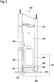
- FIG 1 shows an example of a vehicle 100.
- vehicle 100 may be an aircraft, and, more particularly, an airplane.
- Aircraft 100 is exemplarily embodied with fuselage 102 that includes compartments 102a and 102b.
- a structural separation may separate compartments 102a and 102b of aircraft 100 from each other.
- the structural separation may include a door module 103.
- compartments 102a, 102b may include the cockpit, the cabin, the cargo compartment, etc.
- door module 103 may provide access between the cockpit and the cabin of aircraft 100.
- door module 103 may provide access between the cockpit and the cargo compartment, or between the cabin and the cargo compartment.
- Door module 103 may have a door frame and a door panel.
- the door panel may be attached to the door frame with hinges. During the opening of the door module, the door panel may perform a rotational movement above floor structure 185 of aircraft 100.
- door module 103 may provide a function for dissipating a pressure difference between compartments 102a and 102b of aircraft 100.
- compartments 102a and 102b may be pressurized, and door module 103 may dissipate the pressure difference between compartments 102a and 102b in case of a rapid decompression of one of compartments 102a or 102b.
- Rapid decompression may occur as a result of structural damage to one of compartments 102a or 102b.
- Releasing door module 103 from a closed position and enabling a rapid opening of door module 103 in case of a rapid loss of pressure in one of compartments 102a or 102b may prevent further damage to aircraft 100 by ensuring the establishment of equal pressure in both compartments 102a and 102b.
- FIG. 2 shows illustrative door module 230 that may include mechanical end stop 220, door panel 240, door frame 250, door locking system 260, door damper 270, and door system 290.
- Door system 290 may include deceleration mechanism 280 that is attached to lower region 241 of door panel 240.
- mechanical end stop 220 may be attached to door frame 250. If desired, mechanical end stop 220 may be attached to any other surface that enables mechanical end stop 220 to limit the opening of door panel 240.
- Door damper 270 may bias door panel 240 into a closed position.
- Door damper 270 may be mounted on door panel 240.
- door damper 270 may be mounted on any other surface that enables door damper 270 to bias door panel 240 into the closed position.
- door damper 270 may be mounted on door frame 250, on a surface above door frame 250, on a surface that is perpendicular to door frame 250, etc.
- the door damper 270 may use hydraulic (e.g., oil-filled) dampers.
- spring mechanisms may be used for closing door panel 240.
- door damper 270 may include a compression or torsion spring that stores the energy used in the opening of door panel 240. The spring may release the stored energy to close door panel 240. If desired, door damper 270 may allow for adjustment of the strength of the spring, making it easier or more difficult to push door panel 240 open.
- Door locking system 260 may maintain door panel 240 in a closed position. In other words, door locking system 260 may maintain door panel 240 in a position in which door panel 240 closes door frame 250, thereby denying access through door frame 250. Door locking system 260 may be arranged on door panel 240 and/or on door frame 250.
- door module 230 may be locked (i.e., door locking system 260 may maintain door panel 240 in a position in which door panel 240 closes door frame 250) as soon as the aircraft leaves the parking area and for the entire duration of the flight.
- Door locking system 260 may include a set of electric strikers or bolts that is installed in the side of door panel 240 (i.e., at the edge of the door or near the edge of the door).
- these strikers or bolts are inserted in tumblers mounted in door frame 250 or in openings of door frame 250 that are adapted to receive the strikers or bolts.
- the strikers or bolts may be controlled electrically. More specifically, the strikers or bolts may be powered continuously to ensure that door locking system 260 maintains door panel 240 in a locked position. When the electric power supply is cut off, the strikers or bolts may slide toward an unlocked position, if desired.
- door locking system 260 may release door panel 240 from the closed position under predetermined conditions. For example, door locking system 260 may release door panel 240 from the closed position, if a predetermined air pressure difference threshold between compartments (e.g., compartments 102a and 102b of aircraft 100 of Figure 1 ) is exceeded. Thus, door module 230 may ensure decompression of the compartment with the higher air pressure, thereby harmonizing the air pressure between the compartments.
- a predetermined air pressure difference threshold between compartments (e.g., compartments 102a and 102b of aircraft 100 of Figure 1 ) is exceeded.
- door module 230 may ensure decompression of the compartment with the higher air pressure, thereby harmonizing the air pressure between the compartments.
- door module 230 may separate a cockpit of an aircraft from a cabin of the aircraft.
- the compartments e.g., compartments 102a and 102b of aircraft 100 of Figure 1
- Door panel 240 may be placed perpendicular to floor structure 285 of the aircraft.
- Door panel 240 may be mounted on door frame 250 by hinges that are aligned along an axis perpendicular to the surface of floor structure 285.
- the hinges may be located on the cockpit side of door panel 240 so that the hinges are inaccessible from the cabin.
- Door module 230 may have no gaps between door panel 240 and door frame 250, if desired.
- door panel 240 and door frame 250 may allow the opening of door panel 240 toward the cockpit. It is understood that door panel 240 may be mounted on door frame 250 in a different way. As an example, the hinges may be located on the cabin side of door panel 240 and/or door panel 240 may open toward the cabin.
- door panel 240 may perform a rotational movement around an axis defined by the hinges, thereby moving door panel 240 from the closed position to an open position.
- door panel 240 may be manually moved, moved by a pressure difference, or by a biasing device from the closed position to the open position upon the release of door locking system 260.
- door system 290 may override door locking system 260 and release door panel 240 from the closed position.
- door system 290 may release door panel 240 from the closed position when a difference in pressure between the compartments of an aircraft (e.g., compartments 102a, 102b of aircraft 100 of Figure 1 ) exceeds a predetermined threshold.
- door system 290 may ensure decompression of the compartment with the higher air pressure, thereby harmonizing the air pressure between the compartments.
- door system 290 may be adapted to control the opening of door module 230 under predetermined conditions.
- door system 290 may control the opening of door module 230 if a predetermined air pressure difference threshold between the compartments is exceeded.
- a predetermined air pressure difference may be based on structural specifications of the aircraft and/or on regulations.
- door system 290 may ensure harmonization of the air pressure between the compartments within a predetermined time interval. Harmonization of the air pressure may be achieved by an opening of door module 230 that separates the compartments of the aircraft (e.g., compartments 102a, 102b of Figure 1 ).
- door system 290 may ensure a rapid opening of door panel 240 from the closed position to a first open position to ensure a harmonization of the air pressure between the compartments of the aircraft within a predetermined time interval. Subsequently, door system 290 may decelerate the opening of door panel 240 between the first open position and a second open position to prevent door panel 240 from crashing into a side wall of the aircraft.
- door system 290 may include deceleration mechanism 280 that is attached to lower region 241 of door panel 240. Deceleration mechanism 280 may decelerate the opening of door panel 240. Deceleration mechanism 290 may include casing 281 and brake element 282. Brake element 282 may be arranged outside of casing 281 and above floor structure 285.
- FIGS 3A and 3B show door module 330 with door panel 340 in a closed position and an open position, respectively.
- Door module 330 may include door panel 340, door frame 350, and door system 390, which may include control unit 392 and deceleration mechanism 380 that is attached to a lower region 341 of door panel 340.
- Door panel 340 may be placed perpendicular to floor structure 385 of an aircraft, such as aircraft 100 of Figure 1 .
- Deceleration mechanism 380 may include casing 381, bolt 383, brake element 382 that is rigidly attached to bolt 383, bolt moving mechanism 384 that is attached to bolt 383, latch mechanism 387 that is attached to bolt moving mechanism 384, and activation mechanism 388 that is attached to latch mechanism 387.
- casing 381 of deceleration mechanism 380 may at least be partially integrated into door panel 340.
- Casing 381 may encompass bolt 383 and bolt moving mechanism 384.
- latch mechanism 387 may be mounted on door panel 340.
- Latch mechanism 387 may include pivot arm 387a and blocking component 387b that is rigidly attached to pivot arm 387a.
- Blocking component 387b may be removably connected to bolt moving mechanism 384.
- Blocking component 387b may be adapted to block bolt moving mechanism 384 in a normal mode.
- Bolt moving mechanism 384 may include a spring-loaded mechanism.
- bolt moving mechanism 384 may include a compression spring that is attached to bolt 383. The spring may be loaded in response to a compression that is provided by blocking component 387b.
- the cross-section of blocking component 387b may have any shape that is adapted to block bolt moving mechanism 384 in normal mode. As shown in Figures 3A and 3B , the cross-section of blocking component 387b may have a square shape of which a triangle has been removed.
- Pivot arm 387a may connect blocking component 387b with activation mechanism 388.
- Figure 3A shows door module 330 in a closed position and deceleration mechanism 380 with latch mechanism 387 operating in normal mode.
- Figure 3B shows door module 330 in an open position.
- door module 330 may open slowly. For example, a person may open door module 330 by unlocking a door locking system (e.g., door locking system 260 of Figure 2 ) and moving door panel 340 from the closed position to the open position. In this scenario, door panel 340 may perform rotational movement 386 without any deceleration.
- a door locking system e.g., door locking system 260 of Figure 2
- door panel 340 may perform rotational movement 386 without any deceleration.
- Activation mechanism 388 may switch latch mechanism 387 from the normal mode to a deceleration mode by exerting a rotational force to pivot arm 387a when the predetermined air pressure difference threshold between two compartments that are separated by door module 330 (e.g., compartments 102a, 102b of Figure 1 ) is exceeded.
- activation mechanism 388 may include activation element 388a that activates activation mechanism 388 in response to a trigger.
- the trigger is a signal that is provided by control unit 392 of door system 390.
- Control unit 392 may be connected to activation mechanism 388 and/or the door locking system and may generate a trigger signal when the predetermined air pressure difference threshold between compartments that are separated by door module 330 (e.g., compartments 102a, 102b of Figure 1 ) is exceeded.
- activation element 388a may include an electrical activation element 388a that activates activation mechanism 388 in response to the trigger signal from the control unit 392.
- electrical activation element 388a may include at least one of a solenoid, an electrical actuator, a pyrotechnic actuator, or a gas cartridge. In some embodiments, electrical activation element 388a may override the door locking system that keeps door panel 340 in the closed position.
- the door locking system may have a latching element that protrudes from door panel 340 and extends into door frame 350.
- a solenoid, a pyrotechnical actuator, or any other electrical activation element 388a may push from the door frame 350 against the latching element of the door locking system such that the latching element no longer protrudes from door panel 340, and thus no longer maintains door panel 340 in the closed position.
- control unit 392 of door system 390 may measure the relative pressure difference between the compartments.
- one or more pressure sensors may measure the air pressure in the respective compartments, and control unit 392 may monitor the one or more pressure sensors.
- control unit 392 may generate and send a trigger signal to the door locking system (e.g., door locking system 260 of Figure 2 ) and activation mechanism 388 when the predetermined air pressure difference threshold between the compartments is exceeded.
- activation mechanism 388 may include electrical activation element 388a that activates activation mechanism 388 in response to the trigger signal from control unit 392 of door system 390.
- the door locking system may rapidly unlock door panel 340.
- door locking system may have an electrical locking apparatus and a rapid release mechanism.
- the rapid release mechanism may cut the current to the electrical locking apparatus, thereby unlocking the door locking system.
- activation mechanism 388 of door system 390 may include an override mechanism that overrides the door locking system.
- Door panel 340 may move from a closed position to an open position with rotational movement 386. During rotational movement 386 of door panel 340 from the closed position to the open position, door panel 340 may have a comparatively high kinetic energy which provides a comparatively high acceleration. The acceleration of door panel 340 during rotational movement 386 may be based on a predetermined mass inertia of door panel 340.
- Bolt moving mechanism 384 may exert a predetermined pressure on bolt 383, which in turn pushes brake element 382 onto floor structure 385 to decelerate rotational movement 386 during the opening of door panel 340.
- the predetermined pressure may be selected based on the predetermined mass inertia of door panel 340.
- Brake element 382 may convert the kinetic energy of door panel 340 to thermal energy through friction. Brake element 382 may recover quickly from an increase in temperature. Brake element 382 may be made from a material that enables a smooth and even contact with floor structure 385 during rotational movement 386 of door panel 340.
- brake element 382 may include a material such as sintered glass, aramid, cellulose, composite materials, sintered steel, composed clay bonded to copper, composed porcelain bonded to copper, etc.
- activation mechanism 388 may release latch mechanism 387.
- activation mechanism 388 may release latch mechanism 387 in response to a trigger signal from control unit 392.
- activation mechanism 388 may include a mechanical activation element 388a that releases latch mechanism 387.
- activation mechanism 388 may switch latch mechanism 387 from a normal mode to a deceleration mode.
- pivot arm 387a may pull blocking component 387b from bolt moving mechanism 384.
- bolt moving mechanism 384 may press bolt 383 against brake element 382.
- the interface between bolt moving mechanism 384 and blocking component 387b of latch mechanism 387 may provide a friction.
- the friction between bolt moving mechanism 384 and blocking component 387b may be based at least partially on the predetermined pressure that bolt moving mechanism 384 exerts on bolt 383. If desired, the friction may be based on a predetermined mass inertia of door panel 340 or on a combination of the predetermined pressure that bolt moving mechanism 384 exerts on bolt 383 and the predetermined mass inertia of door panel 340.
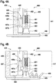
- FIGS 4A and 4B show door module 430 with door panel 440 in a closed and an open position, respectively.
- Door module 430 may include door panel 440, door frame 450, and door system 490, which may include control unit 492 and deceleration mechanism 480. Deceleration mechanism 480 may be attached to a lower region 441 of door panel 440.
- Door panel 440 may be placed perpendicular to floor structure 485.
- Floor structure 485 may be covered by a carpet 486.
- Deceleration mechanism 480 may include casing 481, bolt 483, brake element 482 that is rigidly attached to bolt 483, bolt moving mechanism 484 that is attached to bolt 483, latch mechanism 487 that is removably connected to bolt moving mechanism 484, and activation mechanism 488 that is attached to latch mechanism 487.
- Casing 481 may be attached to door panel 440 and may encompass bolt 483 and bolt moving mechanism 484.
- latch mechanism 487 may be connected to door panel 440.
- Latch mechanism 487 may include pivot arm 487a and blocking component 487b that is rigidly attached to pivot arm 487a.
- Blocking component 487b may be removably connected to bolt moving mechanism 484 and may be adapted to block bolt moving mechanism 484 in the normal mode.
- bolt moving mechanism 484 may include a spring-loaded mechanism.
- bolt moving mechanism 484 may include a spring that is attached to bolt 483. The spring may be loaded in response to a compression that is provided by blocking component 487b.
- Activation mechanism 488 may be attached to pivot arm 487a of latch mechanism 487. Activation mechanism 488 may switch latch mechanism 487 from the normal mode to a deceleration mode by exerting a rotational force to pivot arm 487a when the predetermined air pressure difference threshold between the compartments (e.g., compartments 102a, 102b of Figure 1 ) is exceeded.
- the predetermined air pressure difference threshold between the compartments (e.g., compartments 102a, 102b of Figure 1 ) is exceeded.
- activation mechanism 488 may include activation element 488a that activates activation mechanism 488 in response to a trigger.
- the trigger may be a trigger signal that is provided by control unit 492 of door system 490.
- Control unit 492 may be connected to activation mechanism 488 and/or a door locking system (e.g., door locking system 260 of Figure 2 ) that maintains door panel 440 in the closed position. Control unit 492 may generate a trigger signal when the predetermined air pressure difference threshold between the compartments (e.g., compartments 102a, 102b of Figure 1 ) is exceeded.
- Activation mechanism 488 may include an electrical activation element 488a that is adapted to activate activation mechanism 488 in response to the trigger signal from the control unit 492.
- activation mechanism 488 may override the door locking system such that the door locking system no longer maintains door panel 440 in the closed position.
- door panel 440 may be opened.
- door panel 440 may perform a rotational movement above carpet 486 from the closed to an open position.
- electrical activation element 488a may include a solenoid, an electrical actuator, a pyrotechnic actuator, or a gas cartridge.
- the control unit 492 of door system 490 may measure the relative pressure difference between the compartments, for example using one or more pressure sensors.
- control unit 492 may generate the trigger signal and send the trigger signal to activation mechanism 488 when the predetermined air pressure difference threshold between the compartments is exceeded.
- activation mechanism 488 may include electrical activation element 488a that activates activation mechanism 488 in response to the trigger signal of the control unit 492 of door system 490.
- Door module 430 may have a door locking system (e.g., door locking system 260 of Figure 2 ) that maintains door panel 440 in the closed position.
- Activation mechanism 488 may override the door locking system, thereby unlocking door panel 440.
- door panel 440 may perform a rotational movement 489 from a closed position shown in Figure 4A to the open position shown in Figure 4B .
- the difference in pressure between the compartments may push door panel 440 open once the door locking system no longer maintains door panel 440 in the closed position.
- door panel 440 may have a comparatively high kinetic energy.
- the acceleration of door panel 440 during rotational movement 489 may be associated with a predetermined mass inertia of door panel 440.
- Bolt moving mechanism 484 may exert a predetermined pressure on bolt 483, and thus against brake element 482, thereby pushing brake element 482 onto floor structure 485 that is covered by carpet 486.
- the predetermined pressure on bolt 483 may be based on the predetermined mass inertia of door panel 440 and/or on the required deceleration capabilities of brake element 482 during the interaction with carpet 486 and/or floor structure 485.
- activation mechanism 488 may release latch mechanism 487 by moving blocking component 487b from bolt moving mechanism 484.
- the interface between bolt moving mechanism 484 and blocking component 487b of latch mechanism 487 may provide a friction.
- the friction between bolt moving mechanism 484 and blocking component 487b may depend at least partially on the predetermined pressure that bolt moving mechanism 484 exerts on bolt 483 and/or the mass inertia force of door panel 440.
- the predetermined pressure on bolt 483 may be selected such that mass inertia force of door panel 440 is high enough for latch mechanism 487 to overcome the friction between bolt moving mechanism 484 and blocking component 487b during a rapid opening of door panel 440, thereby releasing bolt moving mechanism 484.
- Brake element 482 may detach carpet 486 from floor structure 485 to decelerate rotational movement 489 of door panel 440.
- brake element 482 may produce more and more carpet wrinkles of carpet 486 during the rotational movement 489 of door panel 440.
- An increase in the number and/or size of the carpet wrinkles may lead to an increasing deceleration of the rotation movement 489 of door panel 440.
- an obstacle such as a side wall and/or a mechanical end stop of door module 430 (e.g., mechanical end stop 220 of Figure 2 ) may completely stop the rotational movement 489 of door panel 440. In other words, the obstacle may absorb the remaining kinetic energy of door panel 440.
- Brake element 482 may fold carpet 486 against the obstacle. Folding carpet 486 against the obstacle may provide a dampening for the door panel 440 before the rotational movement 489 is completely stopped.
- Carpet 486 may have a predetermined shape.
- carpet 486 may have a polygonal shape.
- carpet 486 may be arc-shaped.
- Carpet 486 may at least partially cover the surface of floor structure 485 above which door panel 440 performs rotational movement 489.
- the shape and/or the material and/or the thickness of carpet 486 may be selected to achieve a predetermined folding or wrinkling scheme.
- the predetermined folding or wrinkling scheme may provide for a predetermined number of wrinkles in the carpet when door panel 440 reaches the obstacle.
- the predetermined folding or wrinkling scheme may provide for a predetermined height and width of the wrinkles, etc.
- FIG. 5 is a flow chart 500 showing illustrative operations of using a door system for controlling an opening of a door module that separates first and second compartments of an aircraft.
- the door module may include a door panel that performs a rotational movement above a floor structure of the aircraft during an opening of the door module.
- the door system may determine whether a difference between a first air pressure of the first compartment and a second air pressure of the second compartment exceeds a predetermined air pressure difference threshold.
- door system 290 of Figure 2 may be installed on door module 230 that separates compartments of an aircraft (e.g., compartments 102a, 102b of aircraft 100 of Figure 1 ).
- the door system 290 may determine that the air pressure difference between the compartments that are separated by door module 230 exceeds a predetermined air pressure difference threshold.
- the door system may unlock a door locking system and release the door panel from a closed position, during operation 520.
- door system 290 may unlock door locking system 260 and may release door panel 240 from the closed position.
- the door system may activate an activation mechanism.
- door system 490 of Figures 4A or 4B may activate activation mechanism 488.
- the door system may release a latch mechanism with the activation mechanism.
- door system 490 of Figures 4A or 4B may release latch mechanism 487 with activation mechanism 488.
- the door system may release a bolt moving mechanism with the latch mechanism.
- door system 490 of Figures 4A or 4B may release bolt moving mechanism 484 with latch mechanism 487.
- the door system may, with the bolt moving mechanism, press a bolt against a brake element.
- door system 490 of Figures 4A or 4B may use bolt moving mechanism 484 to press bolt 483 against brake element 482.
- the door system may push the brake element onto the floor structure to decelerate the rotational movement during the opening of the door panel.
- door system 490 of Figures 4A or 4B may push brake element 482 onto floor structure 485 to decelerate rotational movement 489 during the opening of door panel 440.
- deceleration mechanism 380 or 480 of Figures 3A, 3B , 4A, or 4B are shown partially integrated in door panel 340 and 440.
- deceleration mechanism 380 and 480 may be completely integrated or completely detachably attached to door panel 340 and 440.
- casing 381, 481 of deceleration mechanism 380, 480 may include latch mechanism 387, 487, and be detachably mounted on door panel 340, 440.
- casing 381, 481 of deceleration mechanism 380, 480 may be fully integrated to door panel 340, 440 which provides a smooth and straight surface on door panel 340, 440.
- latch mechanism 387, 487 of Figures 3A, 3B , 4A, or 4B is shown with blocking component 387b, 487b that has a cross-section shape in form of a square from which a triangle was removed.
- blocking component 387b, 487b may have any cross-section shape that is suitable to block bolt moving mechanism 384, 484.
- blocking component 387b, 487b may have a cross-section shape in form of a regular trapezoid shape, a triangular shape, a rectangular shape, a square shape, etc.
- bolt moving mechanism 384, 484 of Figures 3A, 3B , 4A, or 4B is shown having a compression spring.
- bolt moving mechanism 384, 484 may include any suitable mechanism that presses bolt 383, 483 against brake element 382, 482.
- bolt moving mechanism 384, 484 may include a piston arm, a torsion spring, a rubber band, an extension spring, etc., or a combination thereof.
Landscapes
- Engineering & Computer Science (AREA)
- Mechanical Engineering (AREA)
- Aviation & Aerospace Engineering (AREA)
- Power-Operated Mechanisms For Wings (AREA)
Priority Applications (2)
| Application Number | Priority Date | Filing Date | Title |
|---|---|---|---|
| EP19400008.9A EP3702265B1 (de) | 2019-02-27 | 2019-02-27 | Türsystem mit einem verzögerungsmechanismus |
| US16/687,963 US11274484B2 (en) | 2019-02-27 | 2019-11-19 | Door system with a deceleration mechanism |
Applications Claiming Priority (1)
| Application Number | Priority Date | Filing Date | Title |
|---|---|---|---|
| EP19400008.9A EP3702265B1 (de) | 2019-02-27 | 2019-02-27 | Türsystem mit einem verzögerungsmechanismus |
Publications (2)
| Publication Number | Publication Date |
|---|---|
| EP3702265A1 true EP3702265A1 (de) | 2020-09-02 |
| EP3702265B1 EP3702265B1 (de) | 2022-04-27 |
Family
ID=66102629
Family Applications (1)
| Application Number | Title | Priority Date | Filing Date |
|---|---|---|---|
| EP19400008.9A Active EP3702265B1 (de) | 2019-02-27 | 2019-02-27 | Türsystem mit einem verzögerungsmechanismus |
Country Status (2)
| Country | Link |
|---|---|
| US (1) | US11274484B2 (de) |
| EP (1) | EP3702265B1 (de) |
Families Citing this family (3)
| Publication number | Priority date | Publication date | Assignee | Title |
|---|---|---|---|---|
| FR3084334B1 (fr) * | 2018-07-24 | 2020-09-11 | Latecoere | Dispositif d'ouverture d'urgence d'une porte d'aeronef, a organe de retenue a levier |
| EP4305653A1 (de) | 2021-03-12 | 2024-01-17 | Essex Industries, Inc. | Wippschalter |
| EP4309200A1 (de) | 2021-03-15 | 2024-01-24 | Essex Industries, Inc. | Fünfstellungsschalter |
Citations (4)
| Publication number | Priority date | Publication date | Assignee | Title |
|---|---|---|---|---|
| US3809419A (en) | 1972-08-28 | 1974-05-07 | J Chezem | Occupant safeguarding door stop |
| US20060048449A1 (en) * | 2002-12-09 | 2006-03-09 | Serge Roques | Door which is intented to be positioned between the cockpit and the cabin of an aircraft |
| US20080054123A1 (en) * | 2006-03-08 | 2008-03-06 | Airbus Deutschland Gmbh | Operation mechanism for activating a deceleration device |
| WO2016057578A1 (en) | 2014-10-06 | 2016-04-14 | Bancroft Resource Management, Llc | Removable, remotely-controlled door locking apparatus |
Family Cites Families (9)
| Publication number | Priority date | Publication date | Assignee | Title |
|---|---|---|---|---|
| US4230350A (en) * | 1979-04-05 | 1980-10-28 | Magic Chef, Inc. | Oven door latch |
| US6866226B2 (en) * | 2001-10-04 | 2005-03-15 | Hartwell Corporation | Pressure responsive blowout latch |
| AT500462B1 (de) * | 2004-04-23 | 2010-02-15 | Knorr Bremse Gmbh | Schiebetür bzw. schwenkschiebetür |
| CA2917564C (en) * | 2013-07-12 | 2021-07-20 | Learjet Inc. | Door for an aircraft |
| US10774569B1 (en) * | 2017-09-15 | 2020-09-15 | Ellington Edwards | Door security device |
| JP6796613B2 (ja) * | 2018-03-28 | 2020-12-09 | 三井金属アクト株式会社 | 開閉装置及び開閉システム |
| EP3636540B1 (de) * | 2018-10-10 | 2020-09-09 | AIRBUS HELICOPTERS DEUTSCHLAND GmbH | Türöffnungssystem mit einem verzögerungsmechanismus |
| EP3683138B1 (de) * | 2019-01-16 | 2021-04-28 | AIRBUS HELICOPTERS DEUTSCHLAND GmbH | Türverriegelungssystem mit einem schnellfreigabemechanismus |
| EP3702264B1 (de) * | 2019-02-28 | 2021-04-21 | AIRBUS HELICOPTERS DEUTSCHLAND GmbH | Türsystem mit einem verzögerungsmechanismus |
-
2019
- 2019-02-27 EP EP19400008.9A patent/EP3702265B1/de active Active
- 2019-11-19 US US16/687,963 patent/US11274484B2/en active Active
Patent Citations (6)
| Publication number | Priority date | Publication date | Assignee | Title |
|---|---|---|---|---|
| US3809419A (en) | 1972-08-28 | 1974-05-07 | J Chezem | Occupant safeguarding door stop |
| US20060048449A1 (en) * | 2002-12-09 | 2006-03-09 | Serge Roques | Door which is intented to be positioned between the cockpit and the cabin of an aircraft |
| US20080054123A1 (en) * | 2006-03-08 | 2008-03-06 | Airbus Deutschland Gmbh | Operation mechanism for activating a deceleration device |
| EP1832508B1 (de) | 2006-03-08 | 2009-01-07 | Airbus Deutschland GmbH | Abbremsmechanismus |
| WO2016057578A1 (en) | 2014-10-06 | 2016-04-14 | Bancroft Resource Management, Llc | Removable, remotely-controlled door locking apparatus |
| US20160186470A1 (en) * | 2014-10-06 | 2016-06-30 | Kenneth Finley | Removable, remotely-controlled door locking apparatus |
Also Published As
| Publication number | Publication date |
|---|---|
| US11274484B2 (en) | 2022-03-15 |
| US20200270926A1 (en) | 2020-08-27 |
| EP3702265B1 (de) | 2022-04-27 |
Similar Documents
| Publication | Publication Date | Title |
|---|---|---|
| EP3683138B1 (de) | Türverriegelungssystem mit einem schnellfreigabemechanismus | |
| US11274484B2 (en) | Door system with a deceleration mechanism | |
| US7568659B2 (en) | Door which is intended to be positioned between the cockpit and the cabin of an aircraft | |
| EP2944562B1 (de) | Passagierflugzeug mit einer notausgangstür | |
| US10807706B2 (en) | Jettisonable emergency exit for a vehicle | |
| CN108116654B (zh) | 具有滑动构件、尤其是滑动门或滑动窗的旋转机翼飞行器 | |
| EP2215321B1 (de) | Dekompressionsverriegelungsmechanismus | |
| JP2010504242A (ja) | 航空機の操縦室扉の施錠解錠システムと、かかるシステムを備えた扉 | |
| US9555872B2 (en) | Aeroplane equipped with an internal escape hatch having a double opening controller | |
| US9540110B2 (en) | Aeroplane equipped with an internal escape hatch incorporating a pressure regulating system | |
| US11208837B2 (en) | Door system with a deceleration mechanism | |
| EP2505492B1 (de) | Sperrmechanismus zur Verwendung in einer Dekompressionsanordnung | |
| EP2167378B1 (de) | Differenzdruckgesteuerter verschlussmechanismus | |
| US10940933B2 (en) | Door opening system with a deceleration mechanism | |
| US11603180B2 (en) | Vehicle with at least one emergency exit system | |
| US11421464B2 (en) | Electromechanical door system for an aircraft | |
| JP4430339B2 (ja) | ドア開閉機構のセーフティロック装置 | |
| EP2554473A2 (de) | Trägerarmanordnung, Tür und Transporteinrichtung | |
| EP3524513B1 (de) | Flugzeugtür für privatsphäre und türrahmenanordnung | |
| AU2006281983A1 (en) | Locking assembly | |
| CN115341807A (zh) | 泄压锁及包括该泄压锁的泄压装置 | |
| CN117326044A (zh) | 用于航空器的门锁定组件 |
Legal Events
| Date | Code | Title | Description |
|---|---|---|---|
| PUAI | Public reference made under article 153(3) epc to a published international application that has entered the european phase |
Free format text: ORIGINAL CODE: 0009012 |
|
| STAA | Information on the status of an ep patent application or granted ep patent |
Free format text: STATUS: THE APPLICATION HAS BEEN PUBLISHED |
|
| AK | Designated contracting states |
Kind code of ref document: A1 Designated state(s): AL AT BE BG CH CY CZ DE DK EE ES FI FR GB GR HR HU IE IS IT LI LT LU LV MC MK MT NL NO PL PT RO RS SE SI SK SM TR |
|
| AX | Request for extension of the european patent |
Extension state: BA ME |
|
| STAA | Information on the status of an ep patent application or granted ep patent |
Free format text: STATUS: REQUEST FOR EXAMINATION WAS MADE |
|
| 17P | Request for examination filed |
Effective date: 20200915 |
|
| RBV | Designated contracting states (corrected) |
Designated state(s): AL AT BE BG CH CY CZ DE DK EE ES FI FR GB GR HR HU IE IS IT LI LT LU LV MC MK MT NL NO PL PT RO RS SE SI SK SM TR |
|
| STAA | Information on the status of an ep patent application or granted ep patent |
Free format text: STATUS: EXAMINATION IS IN PROGRESS |
|
| 17Q | First examination report despatched |
Effective date: 20210128 |
|
| GRAP | Despatch of communication of intention to grant a patent |
Free format text: ORIGINAL CODE: EPIDOSNIGR1 |
|
| STAA | Information on the status of an ep patent application or granted ep patent |
Free format text: STATUS: GRANT OF PATENT IS INTENDED |
|
| INTG | Intention to grant announced |
Effective date: 20220208 |
|
| GRAS | Grant fee paid |
Free format text: ORIGINAL CODE: EPIDOSNIGR3 |
|
| GRAA | (expected) grant |
Free format text: ORIGINAL CODE: 0009210 |
|
| STAA | Information on the status of an ep patent application or granted ep patent |
Free format text: STATUS: THE PATENT HAS BEEN GRANTED |
|
| AK | Designated contracting states |
Kind code of ref document: B1 Designated state(s): AL AT BE BG CH CY CZ DE DK EE ES FI FR GB GR HR HU IE IS IT LI LT LU LV MC MK MT NL NO PL PT RO RS SE SI SK SM TR |
|
| REG | Reference to a national code |
Ref country code: GB Ref legal event code: FG4D |
|
| REG | Reference to a national code |
Ref country code: CH Ref legal event code: EP |
|
| REG | Reference to a national code |
Ref country code: AT Ref legal event code: REF Ref document number: 1486775 Country of ref document: AT Kind code of ref document: T Effective date: 20220515 |
|
| REG | Reference to a national code |
Ref country code: DE Ref legal event code: R096 Ref document number: 602019014130 Country of ref document: DE |
|
| REG | Reference to a national code |
Ref country code: IE Ref legal event code: FG4D |
|
| REG | Reference to a national code |
Ref country code: LT Ref legal event code: MG9D |
|
| REG | Reference to a national code |
Ref country code: NL Ref legal event code: MP Effective date: 20220427 |
|
| REG | Reference to a national code |
Ref country code: AT Ref legal event code: MK05 Ref document number: 1486775 Country of ref document: AT Kind code of ref document: T Effective date: 20220427 |
|
| PG25 | Lapsed in a contracting state [announced via postgrant information from national office to epo] |
Ref country code: NL Free format text: LAPSE BECAUSE OF FAILURE TO SUBMIT A TRANSLATION OF THE DESCRIPTION OR TO PAY THE FEE WITHIN THE PRESCRIBED TIME-LIMIT Effective date: 20220427 |
|
| PG25 | Lapsed in a contracting state [announced via postgrant information from national office to epo] |
Ref country code: SE Free format text: LAPSE BECAUSE OF FAILURE TO SUBMIT A TRANSLATION OF THE DESCRIPTION OR TO PAY THE FEE WITHIN THE PRESCRIBED TIME-LIMIT Effective date: 20220427 Ref country code: PT Free format text: LAPSE BECAUSE OF FAILURE TO SUBMIT A TRANSLATION OF THE DESCRIPTION OR TO PAY THE FEE WITHIN THE PRESCRIBED TIME-LIMIT Effective date: 20220829 Ref country code: NO Free format text: LAPSE BECAUSE OF FAILURE TO SUBMIT A TRANSLATION OF THE DESCRIPTION OR TO PAY THE FEE WITHIN THE PRESCRIBED TIME-LIMIT Effective date: 20220727 Ref country code: LT Free format text: LAPSE BECAUSE OF FAILURE TO SUBMIT A TRANSLATION OF THE DESCRIPTION OR TO PAY THE FEE WITHIN THE PRESCRIBED TIME-LIMIT Effective date: 20220427 Ref country code: HR Free format text: LAPSE BECAUSE OF FAILURE TO SUBMIT A TRANSLATION OF THE DESCRIPTION OR TO PAY THE FEE WITHIN THE PRESCRIBED TIME-LIMIT Effective date: 20220427 Ref country code: GR Free format text: LAPSE BECAUSE OF FAILURE TO SUBMIT A TRANSLATION OF THE DESCRIPTION OR TO PAY THE FEE WITHIN THE PRESCRIBED TIME-LIMIT Effective date: 20220728 Ref country code: FI Free format text: LAPSE BECAUSE OF FAILURE TO SUBMIT A TRANSLATION OF THE DESCRIPTION OR TO PAY THE FEE WITHIN THE PRESCRIBED TIME-LIMIT Effective date: 20220427 Ref country code: ES Free format text: LAPSE BECAUSE OF FAILURE TO SUBMIT A TRANSLATION OF THE DESCRIPTION OR TO PAY THE FEE WITHIN THE PRESCRIBED TIME-LIMIT Effective date: 20220427 Ref country code: BG Free format text: LAPSE BECAUSE OF FAILURE TO SUBMIT A TRANSLATION OF THE DESCRIPTION OR TO PAY THE FEE WITHIN THE PRESCRIBED TIME-LIMIT Effective date: 20220727 Ref country code: AT Free format text: LAPSE BECAUSE OF FAILURE TO SUBMIT A TRANSLATION OF THE DESCRIPTION OR TO PAY THE FEE WITHIN THE PRESCRIBED TIME-LIMIT Effective date: 20220427 |
|
| PG25 | Lapsed in a contracting state [announced via postgrant information from national office to epo] |
Ref country code: RS Free format text: LAPSE BECAUSE OF FAILURE TO SUBMIT A TRANSLATION OF THE DESCRIPTION OR TO PAY THE FEE WITHIN THE PRESCRIBED TIME-LIMIT Effective date: 20220427 Ref country code: PL Free format text: LAPSE BECAUSE OF FAILURE TO SUBMIT A TRANSLATION OF THE DESCRIPTION OR TO PAY THE FEE WITHIN THE PRESCRIBED TIME-LIMIT Effective date: 20220427 Ref country code: LV Free format text: LAPSE BECAUSE OF FAILURE TO SUBMIT A TRANSLATION OF THE DESCRIPTION OR TO PAY THE FEE WITHIN THE PRESCRIBED TIME-LIMIT Effective date: 20220427 Ref country code: IS Free format text: LAPSE BECAUSE OF FAILURE TO SUBMIT A TRANSLATION OF THE DESCRIPTION OR TO PAY THE FEE WITHIN THE PRESCRIBED TIME-LIMIT Effective date: 20220827 |
|
| REG | Reference to a national code |
Ref country code: DE Ref legal event code: R097 Ref document number: 602019014130 Country of ref document: DE |
|
| PG25 | Lapsed in a contracting state [announced via postgrant information from national office to epo] |
Ref country code: SM Free format text: LAPSE BECAUSE OF FAILURE TO SUBMIT A TRANSLATION OF THE DESCRIPTION OR TO PAY THE FEE WITHIN THE PRESCRIBED TIME-LIMIT Effective date: 20220427 Ref country code: SK Free format text: LAPSE BECAUSE OF FAILURE TO SUBMIT A TRANSLATION OF THE DESCRIPTION OR TO PAY THE FEE WITHIN THE PRESCRIBED TIME-LIMIT Effective date: 20220427 Ref country code: RO Free format text: LAPSE BECAUSE OF FAILURE TO SUBMIT A TRANSLATION OF THE DESCRIPTION OR TO PAY THE FEE WITHIN THE PRESCRIBED TIME-LIMIT Effective date: 20220427 Ref country code: EE Free format text: LAPSE BECAUSE OF FAILURE TO SUBMIT A TRANSLATION OF THE DESCRIPTION OR TO PAY THE FEE WITHIN THE PRESCRIBED TIME-LIMIT Effective date: 20220427 Ref country code: DK Free format text: LAPSE BECAUSE OF FAILURE TO SUBMIT A TRANSLATION OF THE DESCRIPTION OR TO PAY THE FEE WITHIN THE PRESCRIBED TIME-LIMIT Effective date: 20220427 Ref country code: CZ Free format text: LAPSE BECAUSE OF FAILURE TO SUBMIT A TRANSLATION OF THE DESCRIPTION OR TO PAY THE FEE WITHIN THE PRESCRIBED TIME-LIMIT Effective date: 20220427 |
|
| PLBE | No opposition filed within time limit |
Free format text: ORIGINAL CODE: 0009261 |
|
| STAA | Information on the status of an ep patent application or granted ep patent |
Free format text: STATUS: NO OPPOSITION FILED WITHIN TIME LIMIT |
|
| PG25 | Lapsed in a contracting state [announced via postgrant information from national office to epo] |
Ref country code: AL Free format text: LAPSE BECAUSE OF FAILURE TO SUBMIT A TRANSLATION OF THE DESCRIPTION OR TO PAY THE FEE WITHIN THE PRESCRIBED TIME-LIMIT Effective date: 20220427 |
|
| 26N | No opposition filed |
Effective date: 20230130 |
|
| PGFP | Annual fee paid to national office [announced via postgrant information from national office to epo] |
Ref country code: FR Payment date: 20230221 Year of fee payment: 5 |
|
| PG25 | Lapsed in a contracting state [announced via postgrant information from national office to epo] |
Ref country code: SI Free format text: LAPSE BECAUSE OF FAILURE TO SUBMIT A TRANSLATION OF THE DESCRIPTION OR TO PAY THE FEE WITHIN THE PRESCRIBED TIME-LIMIT Effective date: 20220427 |
|
| P01 | Opt-out of the competence of the unified patent court (upc) registered |
Effective date: 20230530 |
|
| PG25 | Lapsed in a contracting state [announced via postgrant information from national office to epo] |
Ref country code: MC Free format text: LAPSE BECAUSE OF FAILURE TO SUBMIT A TRANSLATION OF THE DESCRIPTION OR TO PAY THE FEE WITHIN THE PRESCRIBED TIME-LIMIT Effective date: 20220427 |
|
| REG | Reference to a national code |
Ref country code: CH Ref legal event code: PL |
|
| REG | Reference to a national code |
Ref country code: BE Ref legal event code: MM Effective date: 20230228 |
|
| PG25 | Lapsed in a contracting state [announced via postgrant information from national office to epo] |
Ref country code: LU Free format text: LAPSE BECAUSE OF NON-PAYMENT OF DUE FEES Effective date: 20230227 Ref country code: LI Free format text: LAPSE BECAUSE OF NON-PAYMENT OF DUE FEES Effective date: 20230228 Ref country code: CH Free format text: LAPSE BECAUSE OF NON-PAYMENT OF DUE FEES Effective date: 20230228 |
|
| REG | Reference to a national code |
Ref country code: IE Ref legal event code: MM4A |
|
| PG25 | Lapsed in a contracting state [announced via postgrant information from national office to epo] |
Ref country code: IT Free format text: LAPSE BECAUSE OF FAILURE TO SUBMIT A TRANSLATION OF THE DESCRIPTION OR TO PAY THE FEE WITHIN THE PRESCRIBED TIME-LIMIT Effective date: 20220427 Ref country code: IE Free format text: LAPSE BECAUSE OF NON-PAYMENT OF DUE FEES Effective date: 20230227 |
|
| PG25 | Lapsed in a contracting state [announced via postgrant information from national office to epo] |
Ref country code: BE Free format text: LAPSE BECAUSE OF NON-PAYMENT OF DUE FEES Effective date: 20230228 |
|
| PGFP | Annual fee paid to national office [announced via postgrant information from national office to epo] |
Ref country code: DE Payment date: 20240219 Year of fee payment: 6 Ref country code: GB Payment date: 20240219 Year of fee payment: 6 |