EP3702264B1 - Türsystem mit einem verzögerungsmechanismus - Google Patents
Türsystem mit einem verzögerungsmechanismus Download PDFInfo
- Publication number
- EP3702264B1 EP3702264B1 EP19400007.1A EP19400007A EP3702264B1 EP 3702264 B1 EP3702264 B1 EP 3702264B1 EP 19400007 A EP19400007 A EP 19400007A EP 3702264 B1 EP3702264 B1 EP 3702264B1
- Authority
- EP
- European Patent Office
- Prior art keywords
- door
- door panel
- aircraft
- wedge
- shaped component
- Prior art date
- Legal status (The legal status is an assumption and is not a legal conclusion. Google has not performed a legal analysis and makes no representation as to the accuracy of the status listed.)
- Active
Links
- 230000007246 mechanism Effects 0.000 title claims description 92
- 230000004913 activation Effects 0.000 claims description 71
- 230000003993 interaction Effects 0.000 claims description 13
- 230000009467 reduction Effects 0.000 claims description 8
- 238000000034 method Methods 0.000 claims description 7
- 230000004044 response Effects 0.000 claims description 7
- 230000003213 activating effect Effects 0.000 claims description 4
- 238000010586 diagram Methods 0.000 description 14
- 230000006837 decompression Effects 0.000 description 11
- 239000000463 material Substances 0.000 description 8
- 230000008859 change Effects 0.000 description 5
- 230000008878 coupling Effects 0.000 description 5
- 238000010168 coupling process Methods 0.000 description 5
- 238000005859 coupling reaction Methods 0.000 description 5
- 230000006870 function Effects 0.000 description 4
- XEEYBQQBJWHFJM-UHFFFAOYSA-N Iron Chemical compound [Fe] XEEYBQQBJWHFJM-UHFFFAOYSA-N 0.000 description 2
- 229910000831 Steel Inorganic materials 0.000 description 2
- 238000006243 chemical reaction Methods 0.000 description 2
- 238000009420 retrofitting Methods 0.000 description 2
- 238000000926 separation method Methods 0.000 description 2
- 239000010959 steel Substances 0.000 description 2
- 230000007704 transition Effects 0.000 description 2
- 238000013022 venting Methods 0.000 description 2
- RYGMFSIKBFXOCR-UHFFFAOYSA-N Copper Chemical compound [Cu] RYGMFSIKBFXOCR-UHFFFAOYSA-N 0.000 description 1
- 230000001133 acceleration Effects 0.000 description 1
- 239000002131 composite material Substances 0.000 description 1
- 230000006835 compression Effects 0.000 description 1
- 238000007906 compression Methods 0.000 description 1
- 229910052802 copper Inorganic materials 0.000 description 1
- 239000010949 copper Substances 0.000 description 1
- 238000013016 damping Methods 0.000 description 1
- 238000013461 design Methods 0.000 description 1
- 229920001971 elastomer Polymers 0.000 description 1
- 239000000806 elastomer Substances 0.000 description 1
- 238000009434 installation Methods 0.000 description 1
- 229910052742 iron Inorganic materials 0.000 description 1
- 238000012423 maintenance Methods 0.000 description 1
- 229910052751 metal Inorganic materials 0.000 description 1
- 239000002184 metal Substances 0.000 description 1
- 150000002739 metals Chemical class 0.000 description 1
- 230000004048 modification Effects 0.000 description 1
- 238000012986 modification Methods 0.000 description 1
- 230000001681 protective effect Effects 0.000 description 1
- 230000000717 retained effect Effects 0.000 description 1
- 238000010517 secondary reaction Methods 0.000 description 1
- -1 steel Chemical class 0.000 description 1
- 229920001169 thermoplastic Polymers 0.000 description 1
- 239000004416 thermosoftening plastic Substances 0.000 description 1
Images


Classifications
-
- B—PERFORMING OPERATIONS; TRANSPORTING
- B64—AIRCRAFT; AVIATION; COSMONAUTICS
- B64C—AEROPLANES; HELICOPTERS
- B64C1/00—Fuselages; Constructional features common to fuselages, wings, stabilising surfaces or the like
- B64C1/14—Windows; Doors; Hatch covers or access panels; Surrounding frame structures; Canopies; Windscreens accessories therefor, e.g. pressure sensors, water deflectors, hinges, seals, handles, latches, windscreen wipers
- B64C1/1407—Doors; surrounding frames
- B64C1/1469—Doors between cockpit and cabin
-
- E—FIXED CONSTRUCTIONS
- E05—LOCKS; KEYS; WINDOW OR DOOR FITTINGS; SAFES
- E05F—DEVICES FOR MOVING WINGS INTO OPEN OR CLOSED POSITION; CHECKS FOR WINGS; WING FITTINGS NOT OTHERWISE PROVIDED FOR, CONCERNED WITH THE FUNCTIONING OF THE WING
- E05F5/00—Braking devices, e.g. checks; Stops; Buffers
-
- B—PERFORMING OPERATIONS; TRANSPORTING
- B64—AIRCRAFT; AVIATION; COSMONAUTICS
- B64C—AEROPLANES; HELICOPTERS
- B64C1/00—Fuselages; Constructional features common to fuselages, wings, stabilising surfaces or the like
-
- B—PERFORMING OPERATIONS; TRANSPORTING
- B64—AIRCRAFT; AVIATION; COSMONAUTICS
- B64C—AEROPLANES; HELICOPTERS
- B64C1/00—Fuselages; Constructional features common to fuselages, wings, stabilising surfaces or the like
- B64C1/14—Windows; Doors; Hatch covers or access panels; Surrounding frame structures; Canopies; Windscreens accessories therefor, e.g. pressure sensors, water deflectors, hinges, seals, handles, latches, windscreen wipers
- B64C1/1407—Doors; surrounding frames
-
- E—FIXED CONSTRUCTIONS
- E05—LOCKS; KEYS; WINDOW OR DOOR FITTINGS; SAFES
- E05F—DEVICES FOR MOVING WINGS INTO OPEN OR CLOSED POSITION; CHECKS FOR WINGS; WING FITTINGS NOT OTHERWISE PROVIDED FOR, CONCERNED WITH THE FUNCTIONING OF THE WING
- E05F15/00—Power-operated mechanisms for wings
- E05F15/70—Power-operated mechanisms for wings with automatic actuation
- E05F15/72—Power-operated mechanisms for wings with automatic actuation responsive to emergency conditions, e.g. fire
-
- E—FIXED CONSTRUCTIONS
- E05—LOCKS; KEYS; WINDOW OR DOOR FITTINGS; SAFES
- E05F—DEVICES FOR MOVING WINGS INTO OPEN OR CLOSED POSITION; CHECKS FOR WINGS; WING FITTINGS NOT OTHERWISE PROVIDED FOR, CONCERNED WITH THE FUNCTIONING OF THE WING
- E05F3/00—Closers or openers with braking devices, e.g. checks; Construction of pneumatic or liquid braking devices
- E05F3/04—Closers or openers with braking devices, e.g. checks; Construction of pneumatic or liquid braking devices with liquid piston brakes
- E05F3/10—Closers or openers with braking devices, e.g. checks; Construction of pneumatic or liquid braking devices with liquid piston brakes with a spring, other than a torsion spring, and a piston, the axes of which are the same or lie in the same direction
-
- B—PERFORMING OPERATIONS; TRANSPORTING
- B64—AIRCRAFT; AVIATION; COSMONAUTICS
- B64C—AEROPLANES; HELICOPTERS
- B64C1/00—Fuselages; Constructional features common to fuselages, wings, stabilising surfaces or the like
- B64C2001/009—Fuselages; Constructional features common to fuselages, wings, stabilising surfaces or the like comprising decompression panels or valves for pressure equalisation in fuselages or floors
-
- E—FIXED CONSTRUCTIONS
- E05—LOCKS; KEYS; WINDOW OR DOOR FITTINGS; SAFES
- E05Y—INDEXING SCHEME ASSOCIATED WITH SUBCLASSES E05D AND E05F, RELATING TO CONSTRUCTION ELEMENTS, ELECTRIC CONTROL, POWER SUPPLY, POWER SIGNAL OR TRANSMISSION, USER INTERFACES, MOUNTING OR COUPLING, DETAILS, ACCESSORIES, AUXILIARY OPERATIONS NOT OTHERWISE PROVIDED FOR, APPLICATION THEREOF
- E05Y2201/00—Constructional elements; Accessories therefor
- E05Y2201/40—Motors; Magnets; Springs; Weights; Accessories therefor
- E05Y2201/50—Weights
- E05Y2201/502—Wing weights
-
- E—FIXED CONSTRUCTIONS
- E05—LOCKS; KEYS; WINDOW OR DOOR FITTINGS; SAFES
- E05Y—INDEXING SCHEME ASSOCIATED WITH SUBCLASSES E05D AND E05F, RELATING TO CONSTRUCTION ELEMENTS, ELECTRIC CONTROL, POWER SUPPLY, POWER SIGNAL OR TRANSMISSION, USER INTERFACES, MOUNTING OR COUPLING, DETAILS, ACCESSORIES, AUXILIARY OPERATIONS NOT OTHERWISE PROVIDED FOR, APPLICATION THEREOF
- E05Y2201/00—Constructional elements; Accessories therefor
- E05Y2201/60—Suspension or transmission members; Accessories therefor
- E05Y2201/622—Suspension or transmission members elements
- E05Y2201/638—Cams; Ramps
-
- E—FIXED CONSTRUCTIONS
- E05—LOCKS; KEYS; WINDOW OR DOOR FITTINGS; SAFES
- E05Y—INDEXING SCHEME ASSOCIATED WITH SUBCLASSES E05D AND E05F, RELATING TO CONSTRUCTION ELEMENTS, ELECTRIC CONTROL, POWER SUPPLY, POWER SIGNAL OR TRANSMISSION, USER INTERFACES, MOUNTING OR COUPLING, DETAILS, ACCESSORIES, AUXILIARY OPERATIONS NOT OTHERWISE PROVIDED FOR, APPLICATION THEREOF
- E05Y2400/00—Electronic control; Electrical power; Power supply; Power or signal transmission; User interfaces
- E05Y2400/10—Electronic control
- E05Y2400/20—Electronic control of brakes, disengaging means, holders or stops
- E05Y2400/202—Force or torque control
- E05Y2400/21—Force or torque control by controlling the viscosity
-
- E—FIXED CONSTRUCTIONS
- E05—LOCKS; KEYS; WINDOW OR DOOR FITTINGS; SAFES
- E05Y—INDEXING SCHEME ASSOCIATED WITH SUBCLASSES E05D AND E05F, RELATING TO CONSTRUCTION ELEMENTS, ELECTRIC CONTROL, POWER SUPPLY, POWER SIGNAL OR TRANSMISSION, USER INTERFACES, MOUNTING OR COUPLING, DETAILS, ACCESSORIES, AUXILIARY OPERATIONS NOT OTHERWISE PROVIDED FOR, APPLICATION THEREOF
- E05Y2400/00—Electronic control; Electrical power; Power supply; Power or signal transmission; User interfaces
- E05Y2400/10—Electronic control
- E05Y2400/44—Sensors not directly associated with the wing movement
-
- E—FIXED CONSTRUCTIONS
- E05—LOCKS; KEYS; WINDOW OR DOOR FITTINGS; SAFES
- E05Y—INDEXING SCHEME ASSOCIATED WITH SUBCLASSES E05D AND E05F, RELATING TO CONSTRUCTION ELEMENTS, ELECTRIC CONTROL, POWER SUPPLY, POWER SIGNAL OR TRANSMISSION, USER INTERFACES, MOUNTING OR COUPLING, DETAILS, ACCESSORIES, AUXILIARY OPERATIONS NOT OTHERWISE PROVIDED FOR, APPLICATION THEREOF
- E05Y2400/00—Electronic control; Electrical power; Power supply; Power or signal transmission; User interfaces
- E05Y2400/10—Electronic control
- E05Y2400/52—Safety arrangements associated with the wing motor
-
- E—FIXED CONSTRUCTIONS
- E05—LOCKS; KEYS; WINDOW OR DOOR FITTINGS; SAFES
- E05Y—INDEXING SCHEME ASSOCIATED WITH SUBCLASSES E05D AND E05F, RELATING TO CONSTRUCTION ELEMENTS, ELECTRIC CONTROL, POWER SUPPLY, POWER SIGNAL OR TRANSMISSION, USER INTERFACES, MOUNTING OR COUPLING, DETAILS, ACCESSORIES, AUXILIARY OPERATIONS NOT OTHERWISE PROVIDED FOR, APPLICATION THEREOF
- E05Y2900/00—Application of doors, windows, wings or fittings thereof
- E05Y2900/50—Application of doors, windows, wings or fittings thereof for vehicles
- E05Y2900/502—Application of doors, windows, wings or fittings thereof for vehicles for aircraft or spacecraft
Definitions
- the invention is related to a deceleration mechanism for a door system, and, more particularly, to a mechanism for decelerating a door opening movement in case of a compartment decompression in an aircraft.
- the cockpit and cabin of aircrafts are usually pressurized at a pressure that is higher than the ambient pressure.
- the pressure in the cockpit may drop rapidly and become much lower than the pressure in the cabin.
- a bird may strike and break a cockpit window causing such a rapid pressure drop in the cockpit.
- a fast decompression of the cabin is necessary to avoid an aggravating of the situation in which the structural loads of the aircraft could exceed its load limits which would ultimately result in the crash of the aircraft.
- the cockpit door aboard the aircraft provides the primary means of dissipating pressure from the cabin to the cockpit during a cockpit decompression case.
- a cockpit decompression case may occur as a minimal opening involving relatively slow bleed pressure or as a maximum opening involving a rapid loss of pressure.
- the cockpit door must be released and opened within a short time period.
- the time for opening the cockpit door includes the time for releasing the door lock and the time for rotating the door into the open position.
- JAR 25.365(e) (2) specifies that the aircraft structure must be able to withstand the depressurization caused by an instant opening of a predetermined area in the pressurized shell at any operating altitude.
- Document EP 1 832 508 A1 describes an operation mechanism that is adapted for activating a deceleration device for decelerating an opening movement of a door.
- the operation mechanism features a first mode of operation and a second operation mode.
- the operation mechanism allows free rotation of the door, when the operation mechanism is loaded by an impulse of the door below a predetermined threshold value.
- the operation mechanism In the second mode of operation when the operation mechanism is loaded by an impulse of the door above the predetermined threshold value the operation mechanism decelerates free rotation of the door by connecting the door to the deceleration device which will then decelerate the acceleration of the door.
- Document US 2004/0094670 A1 describes a method and apparatus for maintaining a panel in a closed position and releasing a panel upon application of changes resulting from a pressure change in an area adjoining the panel.
- the apparatus includes a latch mechanism attached to a structure that comprises a bolt for engaging a corresponding panel.
- the latch mechanism may be retained on the corresponding panel with the bolt engaging the structure.
- a pressure responsive device is provided to detect a change in pressure on one side of the panel and facilitating release of the bolt in response to a pressure change of a predetermined range or force.
- the latch mechanism and pressure responsive device vent to or communicate with only one side of the panel.
- a reservoir on one side of the panel communicates with a pressure responsive chamber of the pressure responsive device.
- the reservoir is generally on the same side of the panel to provide a pressure volume which is generally isolated from ambient pressure, such as during a decompression event.
- the method includes a method of maintaining a latch mechanism in a closed position subject to a pressure change, including sensing the pressure change on only one side of the panel.
- Document US 3,809,419 A describes occupant safeguarding door stop means expressly designed and adapted for protective use on an interior surface near the lower edge and corner portion of a vertically hinged inwardly openable door. It comprises a mounting base or bracket screwed or otherwise fixed, and a complemental leg member hingedly mounted and depending and having a laterally directed contoured foot portion whose underneath side is equipped with a normally elevated anti-slipping floor engaging shoe.
- Spring means functions to yieldingly lift and release the foot-equipped leg and permits the leg to be forced down to the desired door stop position.
- Releasable spring-loaded latching means functions to hold the door stop in its safety door retaining position.
- Document US 4,230,352 A describes a pivotably mounted door stop linkage having a resilient member acting on the linkage.
- the door stop linkage is adapted to maintain the door stop in position for conventional door operation while allowing rotation of the stop to release the door in reaction to a pressure differential acting across the door.
- the removable, remotely-controlled door locking apparatus includes a housing configured for temporary fixed engagement to a portion of the door.
- the housing has a front facing surface sloped forward and downward at an angle from horizontal as taken from a top to a bottom of the apparatus, and an actuator arranged therein so as to be substantially parallel to the sloping front facing surface between upper and lower ends thereof.
- the apparatus may further include a movable foot attached to the actuator and configured, under actuator control, to be extended in a lock state against a floor surface to secure the door or retracted in an unlock state, based on a wireless signal received from a remote smart device.
- deceleration systems with an activation and/or coupling mechanism are often complicated and heavy.
- deceleration systems often require installations on the door panel which render the door panel heavy and cumbersome to operate. Such systems are also less suited for retrofitting.
- an objective is to provide a door system for controlling an opening of a door module that separates compartments of an aircraft and comprises a door panel and a door frame.
- the door system should enable a controlled opening of the door when the air pressure difference between the area that are separated by the door module exceeds a predetermined threshold.
- the door system should have a simple and light-weight design, have less failure sources than current door systems, and be easy to install.
- the deceleration mechanism should be fast, reliable, and operate without a coupling mechanism.
- an aircraft with a door system that is adapted to control an opening of a door module that separates compartments of the aircraft
- the door module comprises a door panel and a door frame
- the door panel performs a rotational movement above a floor structure of the aircraft during an opening of the door module.
- the door system comprises a deceleration mechanism that is operable in a normal operation mode and a deceleration mode.
- the deceleration mechanism comprises a hinge, a wedge-shaped component, and an activation device.
- the wedge-shaped component is rotatably attached to the hinge, wherein during the rotational movement of the door panel from a closed position to any open position: the wedge-shaped component is embedded in the floor structure of the aircraft to prevent an interaction with the door panel in the normal operation mode, and the wedge-shaped component protrudes from the floor structure of the aircraft and interacts with the door panel such that the rotational movement of the door panel is decelerated at least between a first open position and a second open position in the deceleration mode.
- the activation device is coupled to the wedge-shaped component and switches the deceleration mechanism from operating in the normal operation mode to operating in the deceleration mode when a difference in pressure between the compartments exceeds a predetermined threshold.
- the wedge-shaped component may be integrated in the floor respectively in the floor panel located in front of a door that separates compartments of the aircraft.
- the wedge-shaped component may be activated in the event that a fast decompression situation in one of the compartments occurs.
- the deceleration of the door opening may be controlled over the complete opening angle of the door panel.
- the door panel may be free to move to achieve the needed venting area.
- the wedge-shaped component may perform a controlled deceleration of the door panel. This deceleration is achieved at the interface between the wedge-shaped component and the lower edge of the door panel.
- the wedge-shaped component may be provided with different surfaces and/or geometries and/or different contact pressure and stiffness at the interface to the door panel's lower edge.
- the door system may have less failure sources than conventional door systems.
- the deceleration mechanism may be simply installed and require a low maintenance effort, while providing a fast and reliable activation of the deceleration function.
- the system is well suited for retrofitting and a coupling mechanism may be omitted.
- the door panel may be lightweight, because the declaration mechanism is installed in the floor structure.
- the door module further comprises a door closer that biases the door panel into the closed position.
- the door closer further comprises a door damper that is coupled to the door panel; a first pivot arm that is coupled to the door damper; and a second pivot arm that is coupled between the first pivot arm and the door frame.
- the door system further comprises a pressure sensor that monitors a pressure in at least one of the compartments; and a controller that is coupled to the pressure sensor, monitors the difference in pressure between the compartments of the aircraft, and generates an activation signal when the difference in pressure between the compartments exceeds the predetermined threshold.
- the activation device receives the activation signal from the controller and switches the deceleration mechanism from operating in the normal operation mode to operating in the deceleration mode based on the activation signal.
- the door system further comprises a door locking system that maintains the door panel in the closed position.
- the door locking system further comprises a door release system that overrides the door locking system and releases the door panel from the closed position when the difference in pressure between the compartments exceeds the predetermined threshold.
- the door release system overrides the door locking system based on the activation signal from the controller.
- the wedge-shaped component further comprises a first segment that interacts with the door panel between the closed position and the first open position in the deceleration mode; and a second segment that interacts with the door panel between the first open position and the second open position in the deceleration mode.
- the first segment further comprises a smooth surface that limits interaction with the door panel to ensure a predetermined reduction of the difference in pressure between the compartments within a predetermined time period.
- the second segment further comprises at least one of a wave-shaped or concave-shaped surface that interacts with the door panel such that the rotational movement of the door panel is decelerated.
- the activation device further comprises a movable pin that pushes against the deceleration mechanism; and at least one of a solenoid or a pyrotechnical device, wherein the at least one of the solenoid or the pyrotechnical device pushes the movable pin against the wedge-shaped component such that the deceleration mechanism switches from operating in the normal operation mode to operating in the deceleration mode.
- the deceleration mechanism further comprises a mechanical end stop that stops the door panel at the second open position of the door panel.
- the mechanical end stop is attached to the door frame.
- a method for controlling an opening of a door module using the above-mentioned door system wherein the door module separates first and second compartments of an aircraft and comprises a door panel and a door frame, wherein the door panel performs a rotational movement above a floor structure of the aircraft during an opening of the door module, the method comprising: determining whether a difference between a first air pressure of the first compartment and a second air pressure of the second compartment exceeds a predetermined air pressure difference threshold; in response to determining that the difference between the first air pressure of the first compartment and the second air pressure of the second compartment exceeds the predetermined air pressure difference threshold, overriding a door locking system that keeps the door panel in a closed position, and activating an activation device; with the activation device, pushing against a wedge-shaped component that is embedded in the floor structure of the aircraft such that the wedge-shaped component protrudes from the floor structure of the aircraft and interacts with the door panel; with a smooth surface of the wedge-shaped component limiting interaction with the door panel to ensure
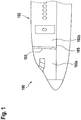
- FIG. 1 shows an aircraft 100, and, more particularly, an airplane.
- Aircraft 100 is exemplarily embodied with fuselage 102 that includes compartments 102a and 102b.
- a structural separation may separate compartments 102a and 102b of aircraft 100 from each other.
- the structural separation may include a door module 103.
- compartments 102a, 102b may include the cockpit, the cabin, the cargo compartment, etc.
- door module 103 may provide access between the cockpit and the cabin of aircraft 100.
- door module 103 may provide access between the cockpit and the cargo compartment, or between the cabin and the cargo compartment.
- Door module 103 has a door frame and a door panel.
- the door panel may be attached to the door frame with hinges. During the opening of the door module, the door panel performs a rotational movement above floor structure 185 of aircraft 100.
- door module 103 may provide a function for dissipating a pressure difference between compartments 102a and 102b of aircraft 100.
- compartments 102a and 102b may be pressurized, and door module 103 may dissipate the pressure difference between compartments 102a and 102b in case of a rapid decompression of one of compartments 102a or 102b.
- Rapid decompression may occur as the result of structural damage to one of compartments 102a or 102b.
- Releasing door module 103 from a closed position and enabling a rapid opening of door module 103 in case of a rapid loss of pressure in one of compartments 102a or 102b may prevent further damage to aircraft 100 by ensuring the establishment of equal pressure in both compartments 102a and 102b.
- Figures 2A and 2B show illustrative door module 230 with a door system 290 having an inactive deceleration mechanism 280 and an activated deceleration mechanism 280, respectively, in accordance with some embodiments.
- Figure 2C is a sectional view of door module 230 of Figures 2A and 2B with door locking system 260 and door release system 262.
- door module 230 may include door panel 240, which is sometimes also referred to as a door blade, door frame 250, and door damper 270.
- Door system 290 may include activation device 210 and deceleration mechanism 280. If desired, door system 290 may include door locking system 260 and/or a door release system 262.
- Door damper 270 may bias door panel 240 into a closed position.
- Door damper 270 may include a compression or torsion spring that stores the energy used in the opening of door panel 240. The spring may release the stored energy to close door panel 240.
- door damper 270 may allow for adjustment of the strength of the spring, making it easier or more difficult to push door panel 240 open.
- the door damper 270 may use hydraulic (e.g., oil-filled) dampers.
- spring mechanisms may be used for damping.
- Door locking system 260 may maintain door panel 240 in the closed position. In other words, door locking system 260 may maintain door panel 240 in a position in which door panel 240 closes door frame 250, thereby denying access through door frame 250. Door locking system 260 may be arranged on door panel 240 and/or on door frame 250.
- FIG. 2C shows a sectional view of illustrative door module 230 with door panel 240 in a closed position 272.
- door module 230 may include door panel 240, door frame 250, door locking system 260 with locking element 245, and hinges 295.
- door panel 240 may prevent passage through door frame 250.
- door locking system 260 with locking element 245 may be part of door system 290.
- door module 230 may be locked (i.e., door locking system 260 may maintain door panel 240 in closed position 272 in which door panel 240 closes door frame 250) as soon as the aircraft leaves the parking area and for the entire duration of the flight.
- Door locking system 260 may include a set of electric strikers or bolts that is installed in the side of door panel 240 (i.e., at the edge of the door or near the edge of the door).
- these strikers or bolts are inserted in tumblers mounted in door frame 250 or in openings of door frame 250 that are adapted to receive the strikers or bolts.
- the strikers or bolts may be controlled electrically. More specifically, the strikers or bolts may be powered continuously to ensure that door locking system 260 maintains door panel 240 in a locked position. When the electric power supply is cut off, the strikers or bolts may slide toward an unlocked position, if desired.
- locking element 245 of door locking system 260 may have at least a first and a second state. Locking element 245 may be adapted to maintain door panel 240 in closed position 272 in the first state. Locking element 245 may be adapted to release door panel 240 from closed position 272 in the second state.
- locking element 245 may be located in door panel 240. In the first state, a latching element of locking element 245 may protrude from door panel 240 into door frame 250, thereby maintaining door panel 240 in closed position 272.
- locking element 245 may be located in door frame 250. In the first state, a latching element of locking element 245 may protrude from door frame 250 into door panel 240, thereby maintaining door panel 240 in closed position 272.
- a biasing element of locking element 245 may bias the latching element into the protruding position, thereby biasing locking element 245 into the first state.
- Door release system 262 may include a locking element release actuator that is coupled to locking element 245.
- the locking element release actuator may perform a transition of locking element 245 from the first state to a second state.
- the transition of locking element 245 from the first state to the second state is sometimes also referred to as the release of locking element 245.
- the locking element release actuator may act on the latching element and/or against the biasing element such that the latching element no longer protrudes from door panel 240 if locking element 245 is located in door panel 240 or from door frame 250 if locking element 245 is located in door frame 250.
- door panel 240 may perform a rotational movement around an axis defined by hinges 295, thereby moving door panel 240 from closed position 272 to open position 274.
- door panel 240 may be manually moved, moved by a pressure difference, or by a biasing device from closed position 272 to open position 274 upon the release of locking element 245.
- door release system 262 of door system 290 may override door locking system 260 and release door panel 240 from the closed position 272.
- door release system 262 may override door locking system 260 under predetermined conditions.
- door release system 262 may release door panel 240 from the closed position 272, when a difference in pressure between the compartments of an aircraft (e.g., compartments 102a, 102b of aircraft 100 of Figure 1 ) exceeds a predetermined threshold.
- door system 290 may ensure decompression of the compartment with the higher air pressure, thereby harmonizing the air pressure between the compartments.
- door system 290 may ensure harmonization of the air pressure between the compartments within a predetermined time interval. Harmonization of the air pressure may be achieved by an opening of door module 230 that separates the compartments of the aircraft (e.g., compartments 102a, 102b of Figure 1 ).
- hinges 295 may attach door panel 240 to door frame 250, and door panel 240 may perform a rotational movement above floor structure 285 of the aircraft and around an axis defined by hinges 295 during the opening of door module 230.
- door module 230 separates a cockpit of an aircraft from a cabin of the aircraft.
- the compartments e.g., compartments 102a and 102b of aircraft 100 of Figure 1
- door panel 240 may be placed perpendicular to floor structure 285 of the aircraft.
- Door panel 240 may be mounted on door frame 250 by hinges 295 that are aligned along an axis perpendicular to the surface of floor structure 285.
- the hinges 295 may be located on the cockpit side of door panel 240 so that the hinges 295 are inaccessible from the cabin.
- Door module 230 may have no gaps between door panel 240 and door frame 250, if desired.
- door panel 240 and door frame 250 may allow the opening of door panel 240 toward the cockpit. It is understood that door panel 240 may be mounted on door frame 250 in a different way. As an example, the hinges 295 may be located on the cabin side of door panel 240 and/or door panel 240 may open towards the cabin.
- Door system 290 is adapted to control the opening of door module 240 under predetermined conditions. Door system 290 controls the opening of door module 240 if a predetermined air pressure difference threshold between the compartments is exceeded. Such a predetermined air pressure difference may be based on structural specifications of the aircraft and/or on regulations.
- Deceleration mechanism 280 of door system 290 includes a hinge and a wedge-shaped component that is rotatably attached to the hinge.
- Figure 2A shows deceleration mechanism 280 operated in a normal mode. When operated in the normal mode, the wedge-shaped component is embedded in floor structure 285 to prevent an interaction with door panel 240 when door panel 240 performs the rotational movement from the closed to any open position.
- activation device 210 of door system 290 that is coupled to the wedge-shaped component of deceleration mechanism 280 switches the deceleration mechanism 280 from operating in the normal operation mode to operating in the deceleration mode.
- activation device 210 may push the wedge-shaped component upwards such that the wedge-shaped component protrudes from the floor structure 285 and interacts with the door panel 240 such that the rotational movement of the door panel 240 is decelerated at least between a first open position and a second open position.
- door module 230 may include a mechanical end stop 220.
- mechanical end stop 220 may be attached to door frame 250.
- mechanical end stop 220 may be attached to any other surface that enables mechanical end stop 220 to limit the opening of door panel 240.
- mechanical end stop 220 may be attached to a wall next to door frame 250.
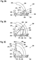
- FIGS 3A, 3B, and 3C illustrate door module 330 with door panel 340 in closed position 392, in first predetermined open position 394, and in second predetermined open position 396, respectively.
- door module 330 may include door panel 340, door frame 350, door system 390, door closer 376, mechanical end stop 320, and door locking system 360.
- Door frame 350 and door panel 340 may be arranged perpendicular to the floor structure and/or the ceiling structure.
- Door panel 340 may be mounted on door frame 350 by hinges that are aligned along an axis perpendicular to the surface of the floor structure. During an opening of door module 330, door panel 340 may perform a rotational movement 389 around the axis defined by the hinges.
- Door locking system 360 may be arranged on door panel 340. If desired, door locking system 360 may be arranged on door frame 350. As shown, mechanical end stop 320 may be attached to door frame 350. If desired, mechanical end stop 320 may be attached to any other surface that enables mechanical end stop 320 to limit the opening of door panel 340. As an example, mechanical end stop 320 may be attached to a compartment wall next to door frame 350.
- Door closer 376 may bias door panel 340 into closed position 392.
- door closer 376 may include door damper 370 and first and second pivot arms 372, 374.
- Door damper 370 may be coupled to door panel 340.
- door damper 370 may include one or more deformation or friction elements such as a spring, a piston, a hydraulic channel and/or a valve that regulates the closing movement.
- Door damper 370 may be mounted to door panel 340. Pivot arm 372 may be coupled to door frame 350, and pivot arm 374 may be coupled between pivot arm 372 and door damper 370. As another example, door damper 370 may be mounted to door frame 350. Pivot arm 372 may be coupled to door panel 340, and pivot arm 374 may be coupled between pivot arm 372 and door damper 370.
- Pivot arm 372 and pivot arm 374 may be attached to each other by means of hinges to form a vertical pivot axis for door panel 340.
- Pivot arms 372, 374 may pivot relative to each other like scissors as door panel 340 performs a rotational movement, their relative angle roughly following the angle of door panel 340 relative to door frame 350.
- Door system 390 includes deceleration mechanism 380 that is operable in a normal operation mode and a deceleration mode.
- Deceleration mechanism 380 includes a hinge, a wedge-shaped component that is rotatably attached to the hinge, and an activation device.
- the cross-sectional view of the wedge-shaped component seen from above or from below may have any shape.
- the cross-sectional view of the wedge-shaped component seen from above or from below may have the shape of a polygon, a segment of a polygon, or a disc segment.
- the cross-sectional view of the wedge-shaped component seen from above or from below may have the shape of an arc or any other portion of the disc segment.
- the disc segment or the arc may encompass a predetermined angle.
- the angle may depend on the opening angle of door panel 340 between closed position 392 and the fully open position.
- the angle may be 180° (i.e., the disc segment may be a half disc or the arc may span 180°).
- the angle may be between 90° (i.e., the disc segment may be a quarter disc or the arc may span 90°).
- the wedge-shaped component is installed in the floor structure above which door panel 340 performs a rotational movement 389 around the axis defined by the hinges to which door panel 340 is attached.
- the wedge-shaped component may be installed in the ceiling below which door panel 340 performs a rotational movement 389 around the axis defined by the hinges to which door panel 340 is attached.
- a first wedge-shaped component is installed in the floor structure above and a second wedge-shaped component may be installed in the ceiling below which door panel 340 performs a rotational movement 389 around the axis defined by the hinges to which door panel 340 is attached.
- the activation device is coupled to the wedge-shaped component.
- the activation device switches the deceleration mechanism 380 from operating in the normal operation mode to operating in the deceleration mode under predetermined conditions.
- the activation device switches the deceleration mechanism 380 from operating in the normal operation mode to operating in the deceleration mode when a difference in pressure between the compartments that are separated by door module 330 exceeds a predetermined threshold.
- the wedge-shaped component In the normal operation mode, the wedge-shaped component is embedded in the floor structure and a second wedge-shaped component may be embedded in the ceiling to prevent an interaction with door panel 340.
- the wedge-shaped component In the deceleration mode, the wedge-shaped component protrudes from the flor structure and optionally also from the ceiling to interact with door panel 340 such that the rotational movement 389 of door panel 340 is decelerated at least between first 394 and second open positions 396.
- door module 330 As an example of the normal operation mode, consider the scenario in which door module 330 is opened slowly. For example, a person may open door module 330 by unlocking door locking system 360 and moving door panel 340 from the closed position to any open position (e.g., open position 394 or open position 396).
- any open position e.g., open position 394 or open position 396.
- the activation device may remain inactive and deceleration mechanism 380 may remain in the normal operation mode.
- the wedge-shaped component of deceleration mechanism 380 may remain embedded in the floor structure and optionally also in the ceiling.
- a pressure sensor system may monitor a pressure in at least one of the compartments.
- door system 390 may include one or more of such pressure sensors.
- a controller may be coupled to the pressure sensor.
- the controller may monitor the difference in pressure between the compartments and generate an activation signal when the difference in pressure between the compartments exceeds a predetermined threshold. If desired, the controller may generate the activation signal based on signals received from the pressure sensor.
- a door release system may override door locking system 360 (e.g., door release system 262 of Figure 2 ), thereby releasing door panel 340 from the closed position 392.
- the activation device that is coupled to the wedge-shaped component may switch deceleration mechanism 380 from operating in the normal operation mode to operating in the deceleration mode.
- the wedge-shaped component may protrude from the floor structure and/or the ceiling such that the wedge-shaped component interacts with door panel 340.
- door panel 340 may rapidly perform a rotational movement 389 from closed position 392 to first predetermined open position 394.
- door panel 340 may have a comparatively high kinetic energy, which may be based on the air pressure difference between the compartments.
- deceleration mechanism 380 of door system 390 may absorb a portion of the kinetic energy of door panel 340.
- the friction between door panel 340 and deceleration mechanism 380 in segment 382 of the wedge-shaped component may be neglected during the rotational movement 389 of door panel 340 from the closed position 392 to the first predetermined open position 394.
- door panel 340 may open rapidly with almost no deceleration when door panel 340 moves from the closed position 392 to the first predetermined open position 394 (see Figure 3B ).
- deceleration mechanism 380 of door system 390 absorbs another portion of the kinetic energy of doorpanel 340.
- the kinetic energy of door panel 340 may be non-zero.
- Mechanical end stop 320 may absorb another portion (e.g., the remainder) of the kinetic energy that door panel 340 may have at the second predetermined open position 396.
- segment 385 of the wedge-shaped component may absorb most of the kinetic energy of door panel 340 during the rotational movement 389 of door panel 340 from the first 394 to the second predetermined open position 396. In other words, the kinetic energy absorbed by segment 385 is greater than the kinetic energy absorbed by segment 382.
- segment 385 may have a surface shape and/or contour that is adapted to decelerate the rotational movement of door panel 340.
- segment 385 and/or the surface of segment 385 may include structural parts that reduce the velocity of (i.e., negatively accelerate or decelerate) the rotational movement of door panel 340.
- the structural parts may include parts that deform plastically. Such structural parts may include any parts that elongate, compress, buckle, or bend. As another example, the structural parts may include parts that transform the kinetic energy of the door panel 340 into heat (e.g., through friction) such as brakes. If desired, the braking mechanism may include a combination of structural parts that deform plastically and structural parts that transform kinetic energy into heat.
- Figures 4A and 4B show an inactive deceleration mechanism 480 (i.e., a deceleration mechanism operating in normal operation mode) and an activated deceleration mechanism 480 (i.e., a deceleration mechanism operating in deceleration mode) of door system 490, respectively.
- an inactive deceleration mechanism 480 i.e., a deceleration mechanism operating in normal operation mode
- an activated deceleration mechanism 480 i.e., a deceleration mechanism operating in deceleration mode
- Door system 490 may be adapted to control an opening of a door module that includes a door panel and a door frame.
- the door panel may be attached to the door frame with hinges.
- the door panel may perform a rotational movement around an axis defined by the hinges.
- deceleration mechanism 480 may include hinge 488 and wedge-shaped component 481 that is rotatably attached to hinge 488.
- Wedge-shaped component 481 is installed in the floor structure 485 at a location above which the door panel performs the rotational movement. In some embodiments not forming part of the invention, the wedge-shaped component 481 may be installed in the ceiling below which the door panel performs the rotational movement. If desired, a first wedge-shaped component 481 is installed in the floor structure 485 and a second wedge-shaped component 481 may be installed in the ceiling.
- wedge-shaped component 481 In the normal operation mode, wedge-shaped component 481 is embedded in the floor structure 485 and optionally an additional wedge-shaped component is installed in the ceiling to prevent an interaction with the door panel. In the deceleration mode, wedge-shaped component 481 protrudes from the floor structure 485 and optionally also the ceiling to interact with the door panel such that the rotational movement of the door panel is decelerated at least between first and second open positions.
- Wedge-shaped component 481 may have different surface shapes and/or surface materials based on the segment and on the desirable deceleration of the rotational movement of the door panel.
- wedge-shaped component 481 may have three segments 483, 484, and 486 that differ from each other in the surface shape and/or the surface material and/or in the height of protrusion from the floor structure 485 and/or the ceiling.
- the door panel initially needs to be free to move into a first open position (e.g., first predetermined open position 394 of Figure 3B ) to achieve the needed venting area and to ensure a predetermined reduction of the difference in pressure between the compartments within a predetermined time period.
- a first open position e.g., first predetermined open position 394 of Figure 3B
- segment 483 may have a smooth surface and/or the height of protrusion from the floor structure 485 may be comparatively small to limit interaction of wedge-shaped component 481 with the door panel and thereby achieve comparatively little deceleration of the rotational movement of the door panel.
- segment 483 may be partially or completely omitted.
- hinge 488 and wedge-shaped component 481 may be attached with each other closer to or at segment 484.
- the velocity of the rotational movement of the door panel should be gradually reduced to zero or almost zero (e.g., to prevent the door panel from crashing into another structure of the aircraft).
- Segments 484 and 486 of wedge-shaped component 481 may interact with the door panel such that the rotational movement of the door panel is decelerated at least between the first open position and the second open position (e.g., between first and second predetermined open positions 394 and 396 of Figure 3C ).
- Segments 484 and 486 may interact with the lower edge of the door panel if wedge-shaped component 481 is embedded in floor structure 485. Segments 484 and 486 may interact with the upper edge of the door panel if wedge-shaped component 481 is embedded in the ceiling.
- Segments 484 and 486 may be provided with different surfaces and/or geometries and/or different contact pressure and stiffness that segment 482.
- segments 484 and/or 486 may have at least one of a wave-shaped or concave-shaped surface that interacts with the door panel such that the velocity of the rotational movement of the door panel is reduced.
- the surface of segments 484 and/or 486 may be made from materials that include one or more materials of high resilience such as elastomers, steel, composite materials, etc.
- the surface of segments 484 and/or 486 may include materials of a high plasticity such as soft thermoplastics and/or metals such as steel, tempered iron, copper, etc.
- the surface of segments 484 and/or 486 may be made from materials of both, high elasticity and high plasticity.
- the height of the protrusion of segments 484 and 486 from floor structure 485 and/or the ceiling may be bigger than the height of the protrusion of segment 483 from floor structure 485 and/or the ceiling to increase the interaction of wedge-shaped component 481 with the door panel and thereby achieve comparatively high deceleration of the rotational movement of the door panel.
- the height of the protrusion of segments 484 and 486 may depend on activation device 410.
- Activation device 410 may be coupled to wedge-shaped component 481.
- Activation device 410 may switch the deceleration mechanism 480 from operating in the normal operation mode shown in Figure 4A to operating in the deceleration mode shown in Figure 4B under predetermined conditions.
- Activation device 410 switches the deceleration mechanism 480 from operating in the normal operation mode to operating in the deceleration mode when a difference in pressure between the compartments that are separated by the door module exceeds a predetermined threshold.
- Activation device 410 may include movable pin 431 and movable pin actuator 432. As shown in Figure 4A , movable pin 431 may be retracted inside movable pin actuator 432 when deceleration mechanism 480 is operating in the normal operation mode. As shown in Figure 4B , movable pin actuator 432 may push movable pin 431 against wedge-shaped component 481 such that movable pin 431 protrudes from movable pin actuator 432 when deceleration mechanism 480 is operating in the deceleration mode. Illustrative activation devices in accordance with some embodiments are shown in Figures 5A and 5B .
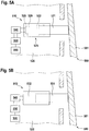
- FIG. 5A is a diagram of illustrative activation device 510 with a pyrotechnical device. As shown in Figure 5A , activation device 510 may be located in floor structure 520 and/or the ceiling. Activation device 510 may be coupled to wedge-shaped component 581 of deceleration mechanism 580.
- activation device 510 may include movable pin 521, pyrotechnical device 525, electrically controlled switch 540, and controller 550.
- pyrotechnical device 525 may include movable pin actuator 522, ignition unit 528, and gas generator 529.
- Figure 5A shows movable pin 521 protruding from pyrotechnical device 525.
- Figure 5A shows activation device 510 when deceleration mechanism 580 is operating in the deceleration mode and movable pin 521 has pushed against wedge-shaped component 581 such that wedge-shaped component 581 protrudes from floor structure 520 and/or the ceiling.
- controller 550 may monitor a pressure in at least one of the compartments (e.g., compartments 102a, 102b of aircraft 100 of Figure 1 ) that are separated by a door module, and controller 550 that is coupled to pressure sensor 555 may monitor the difference in pressure between the compartments. If desired, controller 550 may generate an activation signal when the difference in pressure between the compartments exceeds a predetermined threshold.
- the compartments e.g., compartments 102a, 102b of aircraft 100 of Figure 1
- controller 550 has detected, based on the data from pressure sensor 555, that a difference in pressure between the compartments exceeds a predetermined threshold.
- controller 550 may direct (e.g., based on the activation signal) electrically controlled switch 540 to initiate activation of deceleration mechanism 580.
- electrically controlled switch 540 may send an electrical signal to ignition unit 528.
- ignition unit 528 may transform the electrical energy of the signal into a thermal energy by a chemical reaction. This thermal energy may start a secondary reaction in the adjacent gas generator 529.
- Pyrotechnical device 525 may be designed such that the rate of the gas deployment is extremely high so that movable pin 521 will be pushed into the extracted position, as shown in Figure 5A .
- the projection of movable pin 521 may push against deceleration mechanism 580.
- the projection of movable pin 521 may push against wedge-shaped component 581 such that deceleration mechanism 580 switches from operating in the normal operation mode to operating in the deceleration mode.
- movable pin 521 may push wedge-shaped component 581 upwards from floor structure 520 and/or downwards from the ceiling such that wedge-shaped component 581 protrudes from floor structure 520 and/or the ceiling and interacts with the door panel during an opening of the door module.
- Figure 5B is a diagram of an illustrative activation device with a solenoid bolt in accordance with some embodiments.
- activation device 510 may be located in floor structure 520 and/or the ceiling. Activation device 510 may be coupled to wedge-shaped component 581 of deceleration mechanism 580.
- activation device 510 may include movable pin 531, solenoid 532, electrically controlled switch 540, and controller 550.
- Movable pin 531 may be in a retracted position inside of solenoid 532 in the normal operation mode of deceleration mechanism 580 and it may be deployed from solenoid 532 in the deceleration mode of deceleration mechanism 580.
- controller 550 may monitor a pressure in at least one of the compartments (e.g., compartments 102a, 102b of aircraft 100 of Figure 1 ) that are separated by a door module, and controller 550 that is coupled to pressure sensor 555 may monitor the difference in pressure between the compartments. If desired, controller 550 may generate an activation signal when the difference in pressure between the compartments exceeds a predetermined threshold.
- the compartments e.g., compartments 102a, 102b of aircraft 100 of Figure 1
- controller 550 has detected, based on the data from pressure sensor 555, that a difference in pressure between the compartments exceeds a predetermined threshold.
- controller 550 may direct (e.g., based on the activation signal) electrically controlled switch 540 to initiate activation of deceleration mechanism 580.
- electrically controlled switch 540 may turn on an electrical current through solenoid 532.
- solenoid 532 may generate a magnetic field inside of solenoid 532.
- movable pin 531 may move from a retracted into a protruding position.
- solenoid 532 may push movable pin 531 against deceleration mechanism 580.
- the projection of movable pin 531 may push against wedge-shaped component 581 such that deceleration mechanism 580 switches from operating in the normal operation mode to operating in the deceleration mode.
- movable pin 531 may push wedge-shaped component 581 upwards from floor structure 520 and/or downwards from the ceiling such that wedge-shaped component 581 protrudes from floor structure 520 and/or the ceiling and interacts with the door panel during an opening of the door module.
- FIG. 6 is a flowchart 20 showing illustrative operations for controlling an opening of a door module using a door system (e.g., door system 290 of Figure 2 , door system 390 of Figure 3 , or door system 490 of Figure 4 ) in accordance with some embodiments.
- the door module separates first and second compartments of an aircraft (e.g., door module 103 of Figure 3 that separates compartments 102a, 102b of aircraft 100 of Figure 1 ) and comprises a door panel and a door frame (e.g., door panel 240 and door frame 250 of Figure 2 ).
- the door panel performs a rotational movement above a floor structure of the aircraft during an opening of the door module.
- the door system determines whether a difference between a first air pressure of the first compartment and a second air pressure of the second compartment exceeds a predetermined air pressure difference threshold.
- door module 230 of Figure 2 may separate a cabin from a cockpit or any two other compartments of an aircraft.
- Door system 290 may include a pressure sensor in each of the compartments and a controller that is coupled to the pressure sensors. The controller may monitor the difference between the air pressure in the first compartment and the air pressure in the second compartment, as an example.
- the door system may override a door locking system that keeps the door panel in a closed position, and activate an activation device during operation 620.
- door system 290 of Figure 2 may override door locking system 260 that keeps door panel 240 in a closed position and activate activation device 210.
- controller 550 of Figure 5 may receive a signal from pressure sensor 555 and eventually another signal from another pressure sensor. Based on the signals received, controller 550 may activate activation device 510 that is coupled to wedge-shaped component 581.
- door system 290 may have an additional activation device similar to activation device 510 of which the movable pin 521, 531, upon activation, pushes against a latching element of the door locking system such as to override the door locking system.
- the door system pushes against a wedge-shaped component that is embedded in the floor structure of the aircraft such that the wedge-shaped component protrudes from the floor structure of the aircraft and interacts with the door panel.
- Door system 290 of Figure is integrated into floor structure 285 of an aircraft and pushes with activation device 210 against the wedge-shaped component that is embedded in the floor structure 285 such that the wedge-shaped component protrudes from the floor structure 285 and interacts with the door panel 240.
- the door system limits interaction with the door panel to ensure a predetermined reduction of the difference between the first air pressure of the first compartment and the second air pressure of the second compartment within a predetermined time period during operation 640.
- door system 490 of Figure 4 may, with smooth surface 482 of wedge-shaped component 481, limit interaction with the door panel to ensure a predetermined reduction of the difference between the first air pressure of the first compartment and the second air pressure of the second compartment within a predetermined time period.
- the door system interacts with at least one of a wave-shaped or concave-shaped surface with the door panel such that the rotational movement of the door panel is decelerated.
- door system 490 of Figure 4 may, with wave-shaped surface 484 and/or concave-shaped surface 486 of wedge-shaped component 481, interact with the door panel such that the rotational movement of the door panel is decelerated.
- deceleration mechanism 490 of Figure 4 is shown with three different segments 482, 484, and 486 having one or more different surfaces.
- deceleration mechanism 490 of Figure 4 may have any number of segments with one or more surfaces.
- deceleration mechanism 490 may have a single segment having a uniform surface structure and material. In other words, the deceleration of the rotational movement of the door panel may only depend on the height of protrusion of wedge-shaped component 481 from floor structure 485.
- the edge of the door panel that interacts with wedge-shaped component 481 may have a predetermined surface material that provides predetermined characteristics for interacting with wedge-shaped component 481.
- activation device 210 of Figure 2 or 410 of Figure 4 is shown with a movable pin 431 that pushes against deceleration mechanism 490.
- activation device 210 or 410 may be any device that allows to move wedge-shaped component 481 from a normal operation mode in which wedge-shaped component 481 is embedded in floor structure 485 to a deceleration mode in which wedge-shaped component 481 protrudes from floor structure 485. If desired, the activation device may pull wedge-shaped component 481 instead of push wedge-shaped component 481.
Landscapes
- Engineering & Computer Science (AREA)
- Mechanical Engineering (AREA)
- Aviation & Aerospace Engineering (AREA)
- Business, Economics & Management (AREA)
- Emergency Management (AREA)
- Power-Operated Mechanisms For Wings (AREA)
Claims (15)
- Luftfahrzeug (100) mit einem Türsystem (290), das eingerichtet ist, ein Öffnen eines Türmoduls (103) zu steuern, das Abteile (102a, 102b) des Luftfahrzeugs (100) trennt, wobei das Türmodul (103) ein Türblatt (240) und einen Türrahmen (250) umfasst, wobei das Türblatt (240) während eines Öffnens des Türmoduls (103) eine Drehbewegung (389) oberhalb einer Bodenstruktur (185) des Luftfahrzeugs (100) ausführt, wobei das Türsystem (290) einen Verzögerungsmechanismus (480) umfasst, der in einem normalen Betriebsmodus und einem Verzögerungsmodus betreibbar ist, wobei der Verzögerungsmechanismus (480) umfasst:ein Scharnier (488), undein keilförmiges Bauteil (481), das drehbar an dem Scharnier (488) angebracht ist, dadurch gekennzeichnet, dass während der Drehbewegung (389) des Türblatts (240) von einer geschlossenen Position (392) in eine beliebige offene Position (394, 396):das keilförmige Bauteil (481) in die Bodenstruktur (485) des Luftfahrzeugs (100) eingebettet ist, um eine Wechselwirkung mit dem Türblatt (240) in dem normalen Betriebsmodus zu verhindern, unddas keilförmige Bauteil (481) in dem Verzögerungsmodus aus der Bodenstruktur (485) des Luftfahrzeugs (100) herausragt und mit dem Türblatt (240) derart zusammenwirkt, dass die Drehbewegung (389) des Türblatts (240) zumindest zwischen einer ersten offenen Position (394) und einer zweiten offenen Position (396) verzögert wird; und dadurch gekennzeichnet, dass der Verzögerungsmechanismus ferner umfassteine Aktivierungsvorrichtung (410), die mit dem keilförmigen Bauteil (481) gekoppelt ist und die den Verzögerungsmechanismus (480) vom Betrieb im normalen Betriebsmodus zum Betrieb im Verzögerungsmodus schaltet, wenn eine Druckdifferenz zwischen den Abteilen (102a, 102b) eine vorgegebene Schwelle überschreitet.
- Luftfahrzeug (100) nach Anspruch 1, bei dem das Türmodul (330) ferner umfasst:
einen Türschließer (376), der das Türblatt (340) in die geschlossene Position (392) vorspannt. - Luftfahrzeug (100) nach Anspruch 2, bei dem der Türschließer (376) ferner umfasst:einen Türdämpfer (370), der mit dem Türblatt (340) gekoppelt ist;einen ersten Schwenkarm (372), der mit dem Türrahmen (350) gekoppelt ist; undeinen zweiten Schwenkarm (374), der zwischen dem ersten Schwenkarm (372) und dem Türdämpfer (370) gekoppelt ist.
- Luftfahrzeug (100) nach einem der vorhergehenden Ansprüche, bei dem das Türsystem (290) ferner umfasst:einen Drucksensor (555), der einen Druck in mindestens einem der Abteile (102a, 102b) überwacht; undeine Steuerung (550), die mit dem Drucksensor gekoppelt ist, den Druckunterschied zwischen den Abteilen (102a, 102b) des Luftfahrzeugs (100) überwacht und ein Aktivierungssignal erzeugt, wenn der Druckunterschied zwischen den Abteilen (102a, 102b) den vorgegebenen Schwellenwert überschreitet.
- Luftfahrzeug (100) nach Anspruch 4, bei dem die Aktivierungsvorrichtung (410) das Aktivierungssignal von der Steuerung (550) empfängt und basierend auf dem Aktivierungssignal den Verzögerungsmechanismus (480) vom Betrieb im normalen Betriebsmodus in den Betrieb im Verzögerungsmodus schaltet.
- Luftfahrzeug (100) nach Anspruch 4, bei dem das Türsystem (290) ferner umfasst:
ein Türverriegelungssystem (260), das das Türblatt (240) in der geschlossenen Position hält. - Luftfahrzeug (100) nach Anspruch 6, bei dem das Türsystem (290) ferner umfasst:
ein Türfreigabesystem (262), das das Türverriegelungssystem (260) außer Kraft setzt und das Türblatt (240) aus der geschlossenen Position (292) freigibt, wenn die Druckdifferenz zwischen den Kammern (102a, 102b) den vorgegebenen Schwellenwert überschreitet. - Luftfahrzeug (100) nach Anspruch 7, bei dem das Türfreigabesystem (262) das Türverriegelungssystem (260) basierend auf dem Aktivierungssignal von der Steuerung (550) außer Kraft setzt.
- Luftfahrzeug (100) nach einem der vorhergehenden Ansprüche, bei dem das keilförmige Bauteil (490) ferner umfasst:ein erstes Segment (382), das im Verzögerungsmodus mit dem Türblatt (340) zwischen der geschlossenen Position (392) und der ersten offenen Position (394) zusammenwirkt; undein zweites Segment (385), das im Verzögerungsmodus mit dem Türblatt (340) zwischen der ersten offenen Position (394) und der zweiten offenen Position (396) zusammenwirkt.
- Luftfahrzeug (100) nach Anspruch 9, bei dem das erste Segment (382) ferner umfasst:
eine glatte Oberfläche (482), die die Wechselwirkung mit dem Türblatt (340) begrenzt, um eine vorgegebene Verringerung der Druckdifferenz zwischen den Abteilen (102a, 102b) innerhalb eines vorgegebenen Zeitraums zu gewährleisten. - Luftfahrzeug (100) nach Anspruch 9, bei dem das zweite Segment (385) ferner umfasst:
eine wellenförmige (484) und/oder eine konkav geformte (486) Oberfläche, die mit dem Türblatt (340) zusammenwirkt, so dass die Drehbewegung (389) des Türblatts (340) verzögert wird. - Luftfahrzeug (100) nach einem der vorhergehenden Ansprüche, bei dem die Aktivierungsvorrichtung (510) ferner umfasst:einen beweglichen Stift (521, 531), der gegen den Verzögerungsmechanismus (580) drückt; undeine Betätigungsspule (532) und/oder eine pyrotechnische Vorrichtung (525), wobei die Betätigungsspule und/oder die pyrotechnische Vorrichtung den beweglichen Stift (521, 531) gegen das keilförmige Bauteil (581) drückt, so dass der Verzögerungsmechanismus (580) vom Betrieb im normalen Betriebsmodus zum Betrieb im Verzögerungsmodus umschaltet.
- Luftfahrzeug (100) nach einem der vorhergehenden Ansprüche, bei dem der Verzögerungsmechanismus (380) ferner umfasst:
einen mechanischen Endanschlag (320), der das Türblatt (340) in der zweiten offenen Position (396) des Türblatts (340) anhält. - Luftfahrzeug (100) nach Anspruch 13, bei dem der mechanische Endanschlag (320) an dem Türrahmen (350) angebracht ist.
- Verfahren (600) zum Steuern eines Öffnens eines Türmoduls (230) in dem Luftfahrzeug (100) nach einem der vorhergehenden Ansprüche, wobei das Türmodul (230) ein erstes und ein zweites Abteil (102a, 102b) des Luftfahrzeugs (100) trennt und ein Türblatt (240) und einen Türrahmen (250) umfasst, wobei das Türblatt (240) während eines Öffnens des Türmoduls (103) eine Drehbewegung (389) über einer Bodenstruktur (285) des Luftfahrzeugs (100) ausführt, wobei das Verfahren umfasst:Bestimmen (610), ob eine Differenz zwischen einem ersten Luftdruck des ersten Abteils (102a) und einem zweiten Luftdruck des zweiten Abteils (102b) eine vorgegebene Luftdruckdifferenzschwelle überschreitet;in Reaktion auf das Bestimmen, dass die Differenz zwischen dem ersten Luftdruck des ersten Abteils (102a) und dem zweiten Luftdruck des zweiten Abteils (102b) die vorgegebene Luftdruckdifferenzschwelle überschreitet,
Außerkraftsetzen (620) eines Türverriegelungssystems (260), das das Türblatt (240) in einer geschlossenen Position hält, und Aktivieren einer Aktivierungsvorrichtung (210);dadurch gekennzeichnet, dass es umfasst:mit der Aktivierungsvorrichtung (210), Drücken (630) gegen ein keilförmiges Bauteil (481), das in die Bodenstruktur (285) des Luftfahrzeugs (100) eingebettet ist, so dass das keilförmige Bauteil (481) aus der Bodenstruktur (285) des Luftfahrzeugs (100) herausragt und mit dem Türblatt (240) zusammenwirkt;mit einer glatten Oberfläche (482) des keilförmigen Bauteils (481), Begrenzen (640) der Wechselwirkung mit dem Türblatt (240), um eine vorgegebene Verringerung der Differenz zwischen dem ersten Luftdruck des ersten Abteils (102a) und dem zweiten Luftdruck des zweiten Abteils (102b) innerhalb eines vorgegebenen Zeitraums sicherzustellen; undmit einer wellenförmigen (484) und/oder konkav geformten (486) Oberfläche, Wechselwirken (650) mit dem Türblatt (240) derart, dass die Drehbewegung (389) des Türblattes (240) verzögert wird.
Priority Applications (2)
| Application Number | Priority Date | Filing Date | Title |
|---|---|---|---|
| EP19400007.1A EP3702264B1 (de) | 2019-02-28 | 2019-02-28 | Türsystem mit einem verzögerungsmechanismus |
| US16/687,910 US11208837B2 (en) | 2019-02-28 | 2019-11-19 | Door system with a deceleration mechanism |
Applications Claiming Priority (1)
| Application Number | Priority Date | Filing Date | Title |
|---|---|---|---|
| EP19400007.1A EP3702264B1 (de) | 2019-02-28 | 2019-02-28 | Türsystem mit einem verzögerungsmechanismus |
Publications (2)
| Publication Number | Publication Date |
|---|---|
| EP3702264A1 EP3702264A1 (de) | 2020-09-02 |
| EP3702264B1 true EP3702264B1 (de) | 2021-04-21 |
Family
ID=66102628
Family Applications (1)
| Application Number | Title | Priority Date | Filing Date |
|---|---|---|---|
| EP19400007.1A Active EP3702264B1 (de) | 2019-02-28 | 2019-02-28 | Türsystem mit einem verzögerungsmechanismus |
Country Status (2)
| Country | Link |
|---|---|
| US (1) | US11208837B2 (de) |
| EP (1) | EP3702264B1 (de) |
Families Citing this family (2)
| Publication number | Priority date | Publication date | Assignee | Title |
|---|---|---|---|---|
| EP3702265B1 (de) * | 2019-02-27 | 2022-04-27 | AIRBUS HELICOPTERS DEUTSCHLAND GmbH | Türsystem mit einem verzögerungsmechanismus |
| US11643848B2 (en) * | 2019-05-15 | 2023-05-09 | The Boeing Company | Aircraft panel system, aircraft, and method of operating the aircraft panel system |
Family Cites Families (20)
| Publication number | Priority date | Publication date | Assignee | Title |
|---|---|---|---|---|
| US3809419A (en) | 1972-08-28 | 1974-05-07 | J Chezem | Occupant safeguarding door stop |
| US4230352A (en) | 1979-04-02 | 1980-10-28 | Boeing Commercial Airplane Company | Decompression release door latch and stop |
| US6866227B2 (en) | 2001-10-04 | 2005-03-15 | Hartwell Corporation | Pressure responsive blowout latch with reservoir |
| EP1438473B1 (de) * | 2001-10-04 | 2012-12-05 | The Hartwell Corporation | Druckerfassungsriegel |
| US20030127563A1 (en) * | 2001-10-26 | 2003-07-10 | Laconte Richard J. | Differential pressure sensing release system |
| US6745982B2 (en) * | 2002-01-16 | 2004-06-08 | Northwest Aerospace Technologies, Inc. | Pressure rate of change sensitive latching method and apparatus |
| US20030192989A1 (en) * | 2002-04-10 | 2003-10-16 | Frank Owen | Security bulkhead and door construction |
| FR2848179B1 (fr) * | 2002-12-09 | 2005-11-11 | Airbus France | Porte destinee a etre interposee entre un cockpit et une cabine d'un aeronef |
| JP3947511B2 (ja) * | 2003-10-02 | 2007-07-25 | 株式会社ジャムコ | 航空機の操縦室ドア |
| US7712705B2 (en) * | 2006-03-08 | 2010-05-11 | Airbus Deutschland Gmbh | Deceleration device |
| EP1832508B1 (de) * | 2006-03-08 | 2009-01-07 | Airbus Deutschland GmbH | Abbremsmechanismus |
| JP4263208B2 (ja) * | 2006-11-13 | 2009-05-13 | 株式会社ジャムコ | 航空機の操縦室ドアのラッチ装置 |
| DE102007041387B4 (de) * | 2007-08-31 | 2010-07-01 | Airbus Deutschland Gmbh | Bremsvorrichtung für bewegliches Teil in einem Luftfahrzeug |
| WO2009111776A1 (en) * | 2008-03-07 | 2009-09-11 | Adams Rite Aerospace | Rapid decompression detection system and method |
| DE102011009481A1 (de) * | 2011-01-26 | 2012-07-26 | Airbus Operations Gmbh | Türanordnung mit zwei Türblättern |
| DE102012006357A1 (de) * | 2012-03-29 | 2013-10-02 | Airbus Operations Gmbh | Pneumatisch gesteuertes Verriegelungssystem für die Cockpit-Tür eines Flugzeugs |
| US9114869B1 (en) * | 2013-06-05 | 2015-08-25 | The Boeing Company | Decompression panel and latch |
| US20160186470A1 (en) | 2014-10-06 | 2016-06-30 | Kenneth Finley | Removable, remotely-controlled door locking apparatus |
| US10661881B2 (en) * | 2017-11-13 | 2020-05-26 | The Boeing Company | Flight deck security pocket door decompression venting and crew escape system |
| EP3636540B1 (de) * | 2018-10-10 | 2020-09-09 | AIRBUS HELICOPTERS DEUTSCHLAND GmbH | Türöffnungssystem mit einem verzögerungsmechanismus |
-
2019
- 2019-02-28 EP EP19400007.1A patent/EP3702264B1/de active Active
- 2019-11-19 US US16/687,910 patent/US11208837B2/en active Active
Non-Patent Citations (1)
| Title |
|---|
| None * |
Also Published As
| Publication number | Publication date |
|---|---|
| US11208837B2 (en) | 2021-12-28 |
| US20200277815A1 (en) | 2020-09-03 |
| EP3702264A1 (de) | 2020-09-02 |
Similar Documents
| Publication | Publication Date | Title |
|---|---|---|
| EP3683138B1 (de) | Türverriegelungssystem mit einem schnellfreigabemechanismus | |
| US11274484B2 (en) | Door system with a deceleration mechanism | |
| EP1832508B1 (de) | Abbremsmechanismus | |
| US7568659B2 (en) | Door which is intended to be positioned between the cockpit and the cabin of an aircraft | |
| EP3219601B1 (de) | Entfaltbares abstandsplattensystem, verfahren und anordnung für ein modul in einer internen kabine eines flugzeugs | |
| US11208837B2 (en) | Door system with a deceleration mechanism | |
| CN108116654B (zh) | 具有滑动构件、尤其是滑动门或滑动窗的旋转机翼飞行器 | |
| EP2215321B1 (de) | Dekompressionsverriegelungsmechanismus | |
| US8505850B2 (en) | Locking and unlocking system for the cockpit door of an aircraft and door with such a system | |
| EP1904369B1 (de) | Notöffnungsvorrichtung für ein gepäckfach mit einer absenkbaren schale | |
| EP2505492B1 (de) | Sperrmechanismus zur Verwendung in einer Dekompressionsanordnung | |
| EP2167378B1 (de) | Differenzdruckgesteuerter verschlussmechanismus | |
| US20080226421A1 (en) | Locking Assembly | |
| US10940933B2 (en) | Door opening system with a deceleration mechanism | |
| JPS63149294A (ja) | 乗り物、特に航空機及び宇宙船における非常用出口 | |
| EP4092231B1 (de) | Schnell wirkende elektromechanische entriegelungsvorrichtung und verfahren zur betätigung einer elektromechanischen entriegelungsvorrichtung | |
| JP4430339B2 (ja) | ドア開閉機構のセーフティロック装置 | |
| CN115341807B (zh) | 泄压锁及包括该泄压锁的泄压装置 | |
| EP3838757B1 (de) | Verschlussmechanismus für treppe eines besatzungsruhebereichs | |
| EP3524513B1 (de) | Flugzeugtür für privatsphäre und türrahmenanordnung | |
| AU2006281983A1 (en) | Locking assembly | |
| WO2003070568A1 (en) | Method for controlling aeroplanes |
Legal Events
| Date | Code | Title | Description |
|---|---|---|---|
| PUAI | Public reference made under article 153(3) epc to a published international application that has entered the european phase |
Free format text: ORIGINAL CODE: 0009012 |
|
| STAA | Information on the status of an ep patent application or granted ep patent |
Free format text: STATUS: THE APPLICATION HAS BEEN PUBLISHED |
|
| AK | Designated contracting states |
Kind code of ref document: A1 Designated state(s): AL AT BE BG CH CY CZ DE DK EE ES FI FR GB GR HR HU IE IS IT LI LT LU LV MC MK MT NL NO PL PT RO RS SE SI SK SM TR |
|
| AX | Request for extension of the european patent |
Extension state: BA ME |
|
| STAA | Information on the status of an ep patent application or granted ep patent |
Free format text: STATUS: REQUEST FOR EXAMINATION WAS MADE |
|
| 17P | Request for examination filed |
Effective date: 20200915 |
|
| RBV | Designated contracting states (corrected) |
Designated state(s): AL AT BE BG CH CY CZ DE DK EE ES FI FR GB GR HR HU IE IS IT LI LT LU LV MC MK MT NL NO PL PT RO RS SE SI SK SM TR |
|
| GRAJ | Information related to disapproval of communication of intention to grant by the applicant or resumption of examination proceedings by the epo deleted |
Free format text: ORIGINAL CODE: EPIDOSDIGR1 |
|
| GRAP | Despatch of communication of intention to grant a patent |
Free format text: ORIGINAL CODE: EPIDOSNIGR1 |
|
| GRAP | Despatch of communication of intention to grant a patent |
Free format text: ORIGINAL CODE: EPIDOSNIGR1 |
|
| STAA | Information on the status of an ep patent application or granted ep patent |
Free format text: STATUS: GRANT OF PATENT IS INTENDED |
|
| RIC1 | Information provided on ipc code assigned before grant |
Ipc: E05F 5/00 20170101ALI20201127BHEP Ipc: E05F 3/10 20060101ALI20201127BHEP Ipc: B64C 1/14 20060101AFI20201127BHEP |
|
| INTG | Intention to grant announced |
Effective date: 20201222 |
|
| GRAJ | Information related to disapproval of communication of intention to grant by the applicant or resumption of examination proceedings by the epo deleted |
Free format text: ORIGINAL CODE: EPIDOSDIGR1 |
|
| STAA | Information on the status of an ep patent application or granted ep patent |
Free format text: STATUS: GRANT OF PATENT IS INTENDED |
|
| GRAP | Despatch of communication of intention to grant a patent |
Free format text: ORIGINAL CODE: EPIDOSNIGR1 |
|
| INTG | Intention to grant announced |
Effective date: 20210202 |
|
| GRAS | Grant fee paid |
Free format text: ORIGINAL CODE: EPIDOSNIGR3 |
|
| GRAA | (expected) grant |
Free format text: ORIGINAL CODE: 0009210 |
|
| STAA | Information on the status of an ep patent application or granted ep patent |
Free format text: STATUS: THE PATENT HAS BEEN GRANTED |
|
| AK | Designated contracting states |
Kind code of ref document: B1 Designated state(s): AL AT BE BG CH CY CZ DE DK EE ES FI FR GB GR HR HU IE IS IT LI LT LU LV MC MK MT NL NO PL PT RO RS SE SI SK SM TR |
|
| REG | Reference to a national code |
Ref country code: GB Ref legal event code: FG4D |
|
| REG | Reference to a national code |
Ref country code: CH Ref legal event code: EP |
|
| REG | Reference to a national code |
Ref country code: DE Ref legal event code: R096 Ref document number: 602019004093 Country of ref document: DE |
|
| REG | Reference to a national code |
Ref country code: IE Ref legal event code: FG4D |
|
| REG | Reference to a national code |
Ref country code: AT Ref legal event code: REF Ref document number: 1384369 Country of ref document: AT Kind code of ref document: T Effective date: 20210515 |
|
| REG | Reference to a national code |
Ref country code: LT Ref legal event code: MG9D |
|
| REG | Reference to a national code |
Ref country code: AT Ref legal event code: MK05 Ref document number: 1384369 Country of ref document: AT Kind code of ref document: T Effective date: 20210421 |
|
| REG | Reference to a national code |
Ref country code: NL Ref legal event code: MP Effective date: 20210421 |
|
| PG25 | Lapsed in a contracting state [announced via postgrant information from national office to epo] |
Ref country code: FI Free format text: LAPSE BECAUSE OF FAILURE TO SUBMIT A TRANSLATION OF THE DESCRIPTION OR TO PAY THE FEE WITHIN THE PRESCRIBED TIME-LIMIT Effective date: 20210421 Ref country code: HR Free format text: LAPSE BECAUSE OF FAILURE TO SUBMIT A TRANSLATION OF THE DESCRIPTION OR TO PAY THE FEE WITHIN THE PRESCRIBED TIME-LIMIT Effective date: 20210421 Ref country code: LT Free format text: LAPSE BECAUSE OF FAILURE TO SUBMIT A TRANSLATION OF THE DESCRIPTION OR TO PAY THE FEE WITHIN THE PRESCRIBED TIME-LIMIT Effective date: 20210421 Ref country code: BG Free format text: LAPSE BECAUSE OF FAILURE TO SUBMIT A TRANSLATION OF THE DESCRIPTION OR TO PAY THE FEE WITHIN THE PRESCRIBED TIME-LIMIT Effective date: 20210721 Ref country code: AT Free format text: LAPSE BECAUSE OF FAILURE TO SUBMIT A TRANSLATION OF THE DESCRIPTION OR TO PAY THE FEE WITHIN THE PRESCRIBED TIME-LIMIT Effective date: 20210421 Ref country code: NL Free format text: LAPSE BECAUSE OF FAILURE TO SUBMIT A TRANSLATION OF THE DESCRIPTION OR TO PAY THE FEE WITHIN THE PRESCRIBED TIME-LIMIT Effective date: 20210421 |
|
| PG25 | Lapsed in a contracting state [announced via postgrant information from national office to epo] |
Ref country code: IS Free format text: LAPSE BECAUSE OF FAILURE TO SUBMIT A TRANSLATION OF THE DESCRIPTION OR TO PAY THE FEE WITHIN THE PRESCRIBED TIME-LIMIT Effective date: 20210821 Ref country code: GR Free format text: LAPSE BECAUSE OF FAILURE TO SUBMIT A TRANSLATION OF THE DESCRIPTION OR TO PAY THE FEE WITHIN THE PRESCRIBED TIME-LIMIT Effective date: 20210722 Ref country code: LV Free format text: LAPSE BECAUSE OF FAILURE TO SUBMIT A TRANSLATION OF THE DESCRIPTION OR TO PAY THE FEE WITHIN THE PRESCRIBED TIME-LIMIT Effective date: 20210421 Ref country code: NO Free format text: LAPSE BECAUSE OF FAILURE TO SUBMIT A TRANSLATION OF THE DESCRIPTION OR TO PAY THE FEE WITHIN THE PRESCRIBED TIME-LIMIT Effective date: 20210721 Ref country code: PL Free format text: LAPSE BECAUSE OF FAILURE TO SUBMIT A TRANSLATION OF THE DESCRIPTION OR TO PAY THE FEE WITHIN THE PRESCRIBED TIME-LIMIT Effective date: 20210421 Ref country code: RS Free format text: LAPSE BECAUSE OF FAILURE TO SUBMIT A TRANSLATION OF THE DESCRIPTION OR TO PAY THE FEE WITHIN THE PRESCRIBED TIME-LIMIT Effective date: 20210421 Ref country code: PT Free format text: LAPSE BECAUSE OF FAILURE TO SUBMIT A TRANSLATION OF THE DESCRIPTION OR TO PAY THE FEE WITHIN THE PRESCRIBED TIME-LIMIT Effective date: 20210823 Ref country code: SE Free format text: LAPSE BECAUSE OF FAILURE TO SUBMIT A TRANSLATION OF THE DESCRIPTION OR TO PAY THE FEE WITHIN THE PRESCRIBED TIME-LIMIT Effective date: 20210421 |
|
| REG | Reference to a national code |
Ref country code: DE Ref legal event code: R097 Ref document number: 602019004093 Country of ref document: DE |
|
| PG25 | Lapsed in a contracting state [announced via postgrant information from national office to epo] |
Ref country code: RO Free format text: LAPSE BECAUSE OF FAILURE TO SUBMIT A TRANSLATION OF THE DESCRIPTION OR TO PAY THE FEE WITHIN THE PRESCRIBED TIME-LIMIT Effective date: 20210421 Ref country code: SM Free format text: LAPSE BECAUSE OF FAILURE TO SUBMIT A TRANSLATION OF THE DESCRIPTION OR TO PAY THE FEE WITHIN THE PRESCRIBED TIME-LIMIT Effective date: 20210421 Ref country code: DK Free format text: LAPSE BECAUSE OF FAILURE TO SUBMIT A TRANSLATION OF THE DESCRIPTION OR TO PAY THE FEE WITHIN THE PRESCRIBED TIME-LIMIT Effective date: 20210421 Ref country code: CZ Free format text: LAPSE BECAUSE OF FAILURE TO SUBMIT A TRANSLATION OF THE DESCRIPTION OR TO PAY THE FEE WITHIN THE PRESCRIBED TIME-LIMIT Effective date: 20210421 Ref country code: SK Free format text: LAPSE BECAUSE OF FAILURE TO SUBMIT A TRANSLATION OF THE DESCRIPTION OR TO PAY THE FEE WITHIN THE PRESCRIBED TIME-LIMIT Effective date: 20210421 Ref country code: EE Free format text: LAPSE BECAUSE OF FAILURE TO SUBMIT A TRANSLATION OF THE DESCRIPTION OR TO PAY THE FEE WITHIN THE PRESCRIBED TIME-LIMIT Effective date: 20210421 Ref country code: ES Free format text: LAPSE BECAUSE OF FAILURE TO SUBMIT A TRANSLATION OF THE DESCRIPTION OR TO PAY THE FEE WITHIN THE PRESCRIBED TIME-LIMIT Effective date: 20210421 |
|
| PLBE | No opposition filed within time limit |
Free format text: ORIGINAL CODE: 0009261 |
|
| STAA | Information on the status of an ep patent application or granted ep patent |
Free format text: STATUS: NO OPPOSITION FILED WITHIN TIME LIMIT |
|
| 26N | No opposition filed |
Effective date: 20220124 |
|
| PG25 | Lapsed in a contracting state [announced via postgrant information from national office to epo] |
Ref country code: IS Free format text: LAPSE BECAUSE OF FAILURE TO SUBMIT A TRANSLATION OF THE DESCRIPTION OR TO PAY THE FEE WITHIN THE PRESCRIBED TIME-LIMIT Effective date: 20210821 Ref country code: AL Free format text: LAPSE BECAUSE OF FAILURE TO SUBMIT A TRANSLATION OF THE DESCRIPTION OR TO PAY THE FEE WITHIN THE PRESCRIBED TIME-LIMIT Effective date: 20210421 |
|
| PG25 | Lapsed in a contracting state [announced via postgrant information from national office to epo] |
Ref country code: IT Free format text: LAPSE BECAUSE OF FAILURE TO SUBMIT A TRANSLATION OF THE DESCRIPTION OR TO PAY THE FEE WITHIN THE PRESCRIBED TIME-LIMIT Effective date: 20210421 |
|
| PG25 | Lapsed in a contracting state [announced via postgrant information from national office to epo] |
Ref country code: MC Free format text: LAPSE BECAUSE OF FAILURE TO SUBMIT A TRANSLATION OF THE DESCRIPTION OR TO PAY THE FEE WITHIN THE PRESCRIBED TIME-LIMIT Effective date: 20210421 |
|
| REG | Reference to a national code |
Ref country code: CH Ref legal event code: PL |
|
| REG | Reference to a national code |
Ref country code: BE Ref legal event code: MM Effective date: 20220228 |
|
| PG25 | Lapsed in a contracting state [announced via postgrant information from national office to epo] |
Ref country code: LU Free format text: LAPSE BECAUSE OF NON-PAYMENT OF DUE FEES Effective date: 20220228 |
|
| PG25 | Lapsed in a contracting state [announced via postgrant information from national office to epo] |
Ref country code: LI Free format text: LAPSE BECAUSE OF NON-PAYMENT OF DUE FEES Effective date: 20220228 Ref country code: IE Free format text: LAPSE BECAUSE OF NON-PAYMENT OF DUE FEES Effective date: 20220228 Ref country code: CH Free format text: LAPSE BECAUSE OF NON-PAYMENT OF DUE FEES Effective date: 20220228 |
|
| PG25 | Lapsed in a contracting state [announced via postgrant information from national office to epo] |
Ref country code: BE Free format text: LAPSE BECAUSE OF NON-PAYMENT OF DUE FEES Effective date: 20220228 |
|
| PGFP | Annual fee paid to national office [announced via postgrant information from national office to epo] |
Ref country code: FR Payment date: 20230221 Year of fee payment: 5 |
|
| P01 | Opt-out of the competence of the unified patent court (upc) registered |
Effective date: 20230530 |
|
| PG25 | Lapsed in a contracting state [announced via postgrant information from national office to epo] |
Ref country code: MK Free format text: LAPSE BECAUSE OF FAILURE TO SUBMIT A TRANSLATION OF THE DESCRIPTION OR TO PAY THE FEE WITHIN THE PRESCRIBED TIME-LIMIT Effective date: 20210421 Ref country code: CY Free format text: LAPSE BECAUSE OF FAILURE TO SUBMIT A TRANSLATION OF THE DESCRIPTION OR TO PAY THE FEE WITHIN THE PRESCRIBED TIME-LIMIT Effective date: 20210421 |
|
| PGFP | Annual fee paid to national office [announced via postgrant information from national office to epo] |
Ref country code: DE Payment date: 20240219 Year of fee payment: 6 Ref country code: GB Payment date: 20240219 Year of fee payment: 6 |