EP3702118A1 - Balanced slicing device - Google Patents
Balanced slicing device Download PDFInfo
- Publication number
- EP3702118A1 EP3702118A1 EP20164910.0A EP20164910A EP3702118A1 EP 3702118 A1 EP3702118 A1 EP 3702118A1 EP 20164910 A EP20164910 A EP 20164910A EP 3702118 A1 EP3702118 A1 EP 3702118A1
- Authority
- EP
- European Patent Office
- Prior art keywords
- knife
- cutting knife
- balancing mass
- balancing
- cutting
- Prior art date
- Legal status (The legal status is an assumption and is not a legal conclusion. Google has not performed a legal analysis and makes no representation as to the accuracy of the status listed.)
- Granted
Links
- 238000005520 cutting process Methods 0.000 claims abstract description 116
- 235000013305 food Nutrition 0.000 claims abstract description 4
- 230000005484 gravity Effects 0.000 description 9
- 230000033001 locomotion Effects 0.000 description 7
- 238000010276 construction Methods 0.000 description 4
- 238000011161 development Methods 0.000 description 4
- 230000018109 developmental process Effects 0.000 description 4
- 230000010354 integration Effects 0.000 description 4
- 239000000463 material Substances 0.000 description 3
- 230000000694 effects Effects 0.000 description 2
- 230000004323 axial length Effects 0.000 description 1
- 235000013351 cheese Nutrition 0.000 description 1
- 230000001419 dependent effect Effects 0.000 description 1
- 238000006073 displacement reaction Methods 0.000 description 1
- 230000002349 favourable effect Effects 0.000 description 1
- 238000012423 maintenance Methods 0.000 description 1
- 238000004519 manufacturing process Methods 0.000 description 1
- 230000001681 protective effect Effects 0.000 description 1
- 230000000717 retained effect Effects 0.000 description 1
- 235000013580 sausages Nutrition 0.000 description 1
- 229910001220 stainless steel Inorganic materials 0.000 description 1
- 239000010935 stainless steel Substances 0.000 description 1
- 239000010421 standard material Substances 0.000 description 1
- WFKWXMTUELFFGS-UHFFFAOYSA-N tungsten Chemical compound [W] WFKWXMTUELFFGS-UHFFFAOYSA-N 0.000 description 1
- 229910052721 tungsten Inorganic materials 0.000 description 1
- 239000010937 tungsten Substances 0.000 description 1
- 239000013598 vector Substances 0.000 description 1
Images


Classifications
-
- B—PERFORMING OPERATIONS; TRANSPORTING
- B26—HAND CUTTING TOOLS; CUTTING; SEVERING
- B26D—CUTTING; DETAILS COMMON TO MACHINES FOR PERFORATING, PUNCHING, CUTTING-OUT, STAMPING-OUT OR SEVERING
- B26D7/00—Details of apparatus for cutting, cutting-out, stamping-out, punching, perforating, or severing by means other than cutting
- B26D7/26—Means for mounting or adjusting the cutting member; Means for adjusting the stroke of the cutting member
- B26D7/2614—Means for mounting the cutting member
- B26D7/2621—Means for mounting the cutting member for circular cutters
-
- B—PERFORMING OPERATIONS; TRANSPORTING
- B26—HAND CUTTING TOOLS; CUTTING; SEVERING
- B26D—CUTTING; DETAILS COMMON TO MACHINES FOR PERFORATING, PUNCHING, CUTTING-OUT, STAMPING-OUT OR SEVERING
- B26D1/00—Cutting through work characterised by the nature or movement of the cutting member or particular materials not otherwise provided for; Apparatus or machines therefor; Cutting members therefor
- B26D1/01—Cutting through work characterised by the nature or movement of the cutting member or particular materials not otherwise provided for; Apparatus or machines therefor; Cutting members therefor involving a cutting member which does not travel with the work
- B26D1/12—Cutting through work characterised by the nature or movement of the cutting member or particular materials not otherwise provided for; Apparatus or machines therefor; Cutting members therefor involving a cutting member which does not travel with the work having a cutting member moving about an axis
- B26D1/14—Cutting through work characterised by the nature or movement of the cutting member or particular materials not otherwise provided for; Apparatus or machines therefor; Cutting members therefor involving a cutting member which does not travel with the work having a cutting member moving about an axis with a circular cutting member, e.g. disc cutter
-
- B—PERFORMING OPERATIONS; TRANSPORTING
- B26—HAND CUTTING TOOLS; CUTTING; SEVERING
- B26D—CUTTING; DETAILS COMMON TO MACHINES FOR PERFORATING, PUNCHING, CUTTING-OUT, STAMPING-OUT OR SEVERING
- B26D1/00—Cutting through work characterised by the nature or movement of the cutting member or particular materials not otherwise provided for; Apparatus or machines therefor; Cutting members therefor
- B26D1/01—Cutting through work characterised by the nature or movement of the cutting member or particular materials not otherwise provided for; Apparatus or machines therefor; Cutting members therefor involving a cutting member which does not travel with the work
- B26D1/12—Cutting through work characterised by the nature or movement of the cutting member or particular materials not otherwise provided for; Apparatus or machines therefor; Cutting members therefor involving a cutting member which does not travel with the work having a cutting member moving about an axis
- B26D1/25—Cutting through work characterised by the nature or movement of the cutting member or particular materials not otherwise provided for; Apparatus or machines therefor; Cutting members therefor involving a cutting member which does not travel with the work having a cutting member moving about an axis with a non-circular cutting member
- B26D1/26—Cutting through work characterised by the nature or movement of the cutting member or particular materials not otherwise provided for; Apparatus or machines therefor; Cutting members therefor involving a cutting member which does not travel with the work having a cutting member moving about an axis with a non-circular cutting member moving about an axis substantially perpendicular to the line of cut
- B26D1/28—Cutting through work characterised by the nature or movement of the cutting member or particular materials not otherwise provided for; Apparatus or machines therefor; Cutting members therefor involving a cutting member which does not travel with the work having a cutting member moving about an axis with a non-circular cutting member moving about an axis substantially perpendicular to the line of cut and rotating continuously in one direction during cutting
-
- B—PERFORMING OPERATIONS; TRANSPORTING
- B26—HAND CUTTING TOOLS; CUTTING; SEVERING
- B26D—CUTTING; DETAILS COMMON TO MACHINES FOR PERFORATING, PUNCHING, CUTTING-OUT, STAMPING-OUT OR SEVERING
- B26D7/00—Details of apparatus for cutting, cutting-out, stamping-out, punching, perforating, or severing by means other than cutting
- B26D7/26—Means for mounting or adjusting the cutting member; Means for adjusting the stroke of the cutting member
- B26D7/2614—Means for mounting the cutting member
-
- B—PERFORMING OPERATIONS; TRANSPORTING
- B26—HAND CUTTING TOOLS; CUTTING; SEVERING
- B26D—CUTTING; DETAILS COMMON TO MACHINES FOR PERFORATING, PUNCHING, CUTTING-OUT, STAMPING-OUT OR SEVERING
- B26D1/00—Cutting through work characterised by the nature or movement of the cutting member or particular materials not otherwise provided for; Apparatus or machines therefor; Cutting members therefor
- B26D1/0006—Cutting members therefor
- B26D2001/0046—Cutting members therefor rotating continuously about an axis perpendicular to the edge
-
- B—PERFORMING OPERATIONS; TRANSPORTING
- B26—HAND CUTTING TOOLS; CUTTING; SEVERING
- B26D—CUTTING; DETAILS COMMON TO MACHINES FOR PERFORATING, PUNCHING, CUTTING-OUT, STAMPING-OUT OR SEVERING
- B26D2210/00—Machines or methods used for cutting special materials
- B26D2210/02—Machines or methods used for cutting special materials for cutting food products, e.g. food slicers
- B26D2210/08—Idle cutting
-
- Y—GENERAL TAGGING OF NEW TECHNOLOGICAL DEVELOPMENTS; GENERAL TAGGING OF CROSS-SECTIONAL TECHNOLOGIES SPANNING OVER SEVERAL SECTIONS OF THE IPC; TECHNICAL SUBJECTS COVERED BY FORMER USPC CROSS-REFERENCE ART COLLECTIONS [XRACs] AND DIGESTS
- Y10—TECHNICAL SUBJECTS COVERED BY FORMER USPC
- Y10T—TECHNICAL SUBJECTS COVERED BY FORMER US CLASSIFICATION
- Y10T83/00—Cutting
- Y10T83/869—Means to drive or to guide tool
- Y10T83/8789—With simple revolving motion only
Definitions
- the invention relates to a device for slicing food products, in particular a high-performance slicer, with at least one unbalanced cutting knife rotating around an axis of rotation, a rotary drive for the cutting knife which is arranged on a drive side of the cutting knife, and a counterweight comprising at least one balancing mass to compensate for the imbalance of the cutting knife.
- sickle knives can be used, which rotate at a speed of around 600 to around 2,500 revolutions per minute.
- the sickle knife has a contour that is asymmetrical with respect to the axis of rotation.
- the center of gravity of the knife ie the center of mass of the knife, is thus shifted relative to the axis of rotation.
- an imbalance with a certain imbalance mass or unbalance position results.
- such a cutting device In order to ensure a vibration-free run of the knife, especially at the high speeds that occur, such a cutting device must be balanced in all planes.
- the WO 2010/011237 A1 shows in FIG. 44 B two counterweights, of which one counterweight is arranged in front of the knife and one counterweight behind the knife, viewed in the axial direction.
- the DE 10 2008 019 776 A1 describes a knife with a large central opening.
- the knife is pushed over a counterweight of a knife holder. In the cutting position, the counterweight is therefore in front of the cutting knife.
- the production of such a slicing device and the corresponding knives is, however, comparatively cost-intensive due to the complex construction.
- unbalance also generally means an unbalanced mass, an unbalanced position and / or an unbalanced mass, depending on the context to understand the rotation due to the unbalanced mass effective force in terms of magnitude and direction.
- axial distances i.e. distances measured along the axis of rotation of the knife, relative to a cutting knife relate to a cutting plane defined by the knife, while the axial position of a balancing mass or imbalance relates to a plane that runs perpendicular to the axis of rotation of the knife and in which the center of gravity of the balance mass or imbalance lies.
- information on the position or direction of action of a balancing mass also relate here, unless otherwise stated, to the imbalance generated by the balancing mass or by the component or assembly in which the balancing mass in question is integrated.
- a balancing mass in a component or assembly of the device is understood in the sense of a targeted addition of an additional mass, then it is clear to the person skilled in the art that this is synonymous with a targeted removal of material from a component or assembly, mathematically speaking with a targeted addition of a "negative balancing mass", that is to say generally with the targeted generation of an imbalance on or in the relevant component or assembly.
- the counterweight is arranged exclusively on one side of the cutting knife.
- the invention means a departure from balancing concepts known from the prior art in which the counterweight is divided between both knife sides, that is, at least one balancing mass is arranged in front of and at least one further balancing mass is arranged behind the knife.
- the side on which the counterweight is located can be the drive side of the knife. But this is not mandatory.
- the side of the counterweight can also be the knife side from which the products are fed to the knife. Depending on the structure of the respective slicer, this feed side can be identical to the drive side, although this is not mandatory.
- all balancing masses are not located on the side of the knife which is intended for dismantling the knife, ie, viewed from the dismantling side of the knife, all balancing masses are on the other side of the knife. If the knife has to be removed forwards, for example, all the balancing masses are located behind the knife, so that no balancing mass has to be moved to dismantle the knife.
- balancing mass is therefore provided on the dismantling side of the knife.
- Any components located on this side for example part of a hub or fastening means, e.g. Screws are only used to fasten the cutting knife or for other purposes, but not to compensate for the imbalance of the cutting knife.
- the side of the knife free from balancing masses, in particular the dismantling side can be identical to the side on which the cut products are transported away, although this is not mandatory and depends on the respective slicer concept. There are slicer concepts in which the drive side and the dismantling side of the knife are on the same knife side and thus opposite the product feed side.
- the counterweight is adapted to the knife mass or knife shape, which determines the imbalance of the cutting knife.
- the complete arrangement of the counterweight according to the invention i.e. all the balancing masses provided, enables or facilitates particularly advantageous balancing concepts only on one side of the knife, which are discussed in more detail below in connection with further independent aspects of the invention.
- the cutting knife is removably attached to a knife holder.
- the knife holder forms a balancing mass and has an asymmetrical rotational geometry with respect to the axis of rotation.
- the knife holder itself that forms a balancing mass used to balance the knife.
- This concept makes it possible to position the required balancing mass on the one hand axially close to the knife and on the other hand relatively far outside in the radial direction, which makes a particularly efficient balancing concept possible overall. Due to the asymmetrical design of the knife holder, a sufficiently large imbalance can be generated with a relatively low total weight of the knife holder.
- This shape of the knife holder which is asymmetrical with respect to the axis of rotation, means a departure from concepts known from the prior art for the knife holder, in which it is crucial to provide a knife holder with a rotational geometry that is symmetrical with respect to the axis of rotation, in particular with a circular outer contour concentric to the axis of rotation , which is required to seal a correspondingly circular opening in a housing or frame of the slicer or to form a narrow annular gap with this opening.
- the knife holder can, according to the invention, deviate extremely from a circular outer contour and, to a certain extent, be very top-heavy - based on the radial direction - that is, have a relatively large imbalance or imbalance mass, for example - figuratively speaking - like a rotating hammer.
- the knife holder can e.g. comprise a first section and a second section, wherein the first section forms the largest radius of the knife holder, the axis of rotation extends through the second section, and the center of mass of the first section is located radially further out than the center of mass of the second section.
- the knife holder can e.g. be shaped at least approximately in the manner of an anchor, a relatively heavy circular ring section being arranged radially on the outside on a comparatively light central section through which the axis of rotation runs.
- the outer circular ring section can extend, for example, over at least 1/7, 1/6, 1/5, 1/4 or 1/3 of the outer circumference of the knife holder.
- the knife holder itself forms a balancing mass, the construction is particularly simple. In this way, the balancing mass is also particularly close to the cutting plane axially. A further, separate balancing mass in the axial vicinity of the cutting knife is therefore not necessary.
- the knife holder thus fulfills a double function, since on the one hand it carries the knife and on the other hand it compensates for at least part of the imbalance of the cutting knife.
- Knives of different sizes can thus be used in a simple manner.
- the balancing mass or one of the balancing masses is formed by the rotary drive, in particular by a drive pulley or a hub that can be set in rotation by means of a drive motor via a drive belt.
- the rotary drive fulfills a double function, since on the one hand it sets the cutting knife in rotation and, on the other hand, it compensates at least part of the imbalance of the cutting knife.
- the rotary drive due to the balancing mass or the imbalance together with the cutting knife forms a mass system that can be designed in terms of dimensioning and arrangement such that the overall center of gravity of the rotating system is on that side of the cutting knife on which the rotary drive is also located.
- this center of gravity is "pulled” to its side by the imbalance in the rotary drive. Consequently, it is possible to also arrange a further balancing mass on this side of the cutting knife, so that all balancing masses are only on one side of the cutting knife.
- the balancing mass of the rotary drive can be at a large axial distance from the cutting plane to be ordered. This results, so to speak, in a relatively large leverage effect of the balancing mass, which therefore only needs to have a comparatively low weight, which in turn facilitates its integration into the rotary drive or even enables it in the first place.
- the balancing mass formed by the rotary drive can bring about optimal balancing of the entire rotating system in all planes, both statically and dynamically, and this with an extremely compact design of the Overall arrangement.
- a knife holder itself which may serve as a balancing mass in addition to the rotary drive, does not necessarily have to be exchanged, but it is possible to change both the knife holder and the drive disk or hub when changing a knife, the latter in particular if this is not possible or not it is desired to compensate for the change in the imbalance to be compensated associated with a knife change exclusively by exchanging the knife holder.
- the drive pulley can be, for example, a toothed belt pulley which is set in rotary motion by a motor-driven toothed belt.
- the drive pulley can, for example, drive a shaft which carries the knife holder and thus the knife and is set in rotation and which is rotatably mounted in a stationary hub.
- a particularly hollow cylindrical one Hub can be provided, which is set in rotation, for example via a motor-driven toothed belt, and which carries the knife holder and thus the knife and sets it in rotation, the hub being rotatably mounted on a shaft or spindle which is itself rotatable relative to the knife.
- the driven shaft or the driven hub can carry the knife holder designed as a separate component or can itself be designed as a knife holder. If a rotationally driven hub is designed as a knife holder at the same time, the hub can each contain a balancing mass at at least two axially spaced locations or act as an imbalance in order to compensate for the imbalance of the knife.
- the counterweight formed by the imbalance masses or the imbalances is provided by a single component - namely the hub that is rotationally driven on the one hand and the hub carrying the knife that is affected by the imbalance on the other hand - which is arranged on one side of the knife, so that in this variant all of the balancing masses or imbalances provided to compensate for the knife imbalance only need to be arranged on one side of the knife.
- the rotary drive is in particular axially spaced from the cutting knife, for example in a range between 150 mm and 500 mm, preferably from 150 mm to 300 mm.
- the counterweight does not just comprise a single balancing mass, but rather several balancing masses that are axially spaced from one another.
- exactly two balancing masses are provided.
- a balancing mass to be arranged axially close to the knife, for example in the form of a correspondingly asymmetrically designed knife holder, and a further balancing mass to be positioned at a greater axial distance from the knife, for example in the rotary drive or as part of the rotary drive.
- the concept of several, especially two, balancing masses in addition to the imbalance of the knife can, with appropriate dimensioning and arrangement of the balancing masses depending on the knife imbalance, advantageously make use of the fact that the center of gravity of the imbalance on the one hand and the centers of gravity of the individual balancing masses on the other hand strive for a common focus of the entire rotating system.
- a counterweight is provided to compensate for the imbalance of the cutting knife, which counterweight comprises at least two axially spaced apart balancing masses.
- a first balancing mass and the unbalance of the cutting knife are effective at least approximately in opposite radial directions, while a second balancing mass is effective at least approximately in the same radial direction as the unbalance of the cutting knife.
- the first balancing mass is arranged closer to the cutting knife in the axial direction than the second balancing mass.
- a first balancing mass is arranged at an axial distance from the cutting knife which is many times smaller than the axial distance between a second balancing mass and the cutting knife.
- the first balancing mass is in particular very close to the cutting knife and can e.g. be integrated into a knife holder, be part of the knife holder or be formed by the knife holder.
- the second balancing mass can be selected to be relatively small due to the relatively great leverage that this creates. As a result, only a small mass needs to be accelerated or set in rotation.
- a first balancing mass (or its imbalance or the imbalance of a component or assembly comprising the first balancing mass) is at an axial distance of a maximum of 50 mm, 40 mm, 35 mm, 30 mm or 25 mm, preferably a maximum 20 mm, arranged from the cutting knife.
- a second balancing mass (or its imbalance or the imbalance of a component or assembly comprising the second balancing mass) is at an axial distance of 100 mm to 2,000 mm, in particular from 150 mm to 500 mm, particularly preferably from 150 mm to 300 mm, arranged by the cutting knife.
- the distance between the first balancing mass and the second balancing mass can for example be at least 50 mm, 75 mm, 100 mm, 150 mm, 200 mm, 300 mm, 500 mm, 1,000 mm, 1,500 mm or 2,000 mm.
- a first balancing mass or its imbalance is greater than the imbalance of the cutting knife.
- the sum of the imbalance of the cutting knife and a second balancing mass or its imbalance is equal to or approximately equal to the first balancing mass or its imbalance.
- a first balancing mass extends up to a radial distance from the axis of rotation which is at least 75%, in particular 90% and preferably at least approximately 100% of the smallest radius of the cutting knife, in particular the first balancing mass being arranged closer to the cutting knife in the axial direction is as a second balancing mass.
- the largest radius of the knife holder is at least 75%, in particular 90% and preferably at least approximately 100% of the smallest radius of the cutting knife.
- the knife holder can consequently extend at least in a partial area of its circumference in the radial direction to the smallest radius of the cutting knife, which is impossible with arrangements known from the prior art due to an overall concept that is fundamentally different from the invention. This is e.g. then the case when the knife holder has to close a comparatively small housing or frame opening and must therefore have a circular shape with a relatively small radius, or when the knife has a comparatively large opening for attaching the knife holder.
- the first balancing mass is located radially relatively far outside, that is, it is spaced relatively far from the axis of rotation of the cutting blade.
- the first balancing mass can be made comparatively small become. This in turn makes it possible to place the first balancing mass in the axial direction comparatively close to the unbalance of the knife and thus close to the cutting plane.
- a second balancing mass can also be selected to be comparatively small, and this in particular the more the further the second balancing mass is axially away from the cutting knife.
- Such an arrangement of the balancing masses means that only relatively small masses have to be moved. This is particularly advantageous both for the rotary movement of the knife and for an axial knife movement that may be required during the rotary operation, in particular for a clocked axial movement for performing blank cuts. This also allows the dimensioning and control of the rotary and axial drives to be optimized.
- such a balancing concept can be implemented in a particularly simple and yet effective manner according to a preferred embodiment of the invention, in that the first balancing mass is formed by a knife holder and the second balancing mass by the rotary drive of the knife.
- a knife holder and the rotary drive are arranged on different sides of a stationary frame or frame part.
- the frame or frame part serves in particular for the axially spaced fastening of the knife holder via a hub through which a drive shaft extending from the rotary drive to the knife holder is passed.
- the knife receptacle is consequently spaced apart from the frame or frame part in the axial direction. In this way there is a gap between the knife holder and the frame or frame part.
- a first balancing mass and a second balancing mass are arranged on different sides of a stationary frame or frame part.
- the frame or frame part forms at least part of an outer wall of a drive housing for the rotary drive that faces the cutting knife.
- the "second balancing mass" referred to above which is located axially further away from the cutting knife than the other balancing mass, is preferably arranged in a hygienically uncritical area, for example in a drive housing.
- the device according to the invention is preferably designed such that what is known as fine balancing can be carried out in order to be able to balance the system as precisely as possible.
- the fine balancing can e.g. by adding or removing small weights, in particular on or in the area of at least one balancing mass that is provided anyway.
- fine balancing has hitherto always been carried out in the vicinity of the cutting knife, according to a preferred development of the invention, in the case of providing two balancing masses, fine balancing be carried out on or in the area of the balancing mass located axially further away from the cutting knife, which is in particular the above as “second balancing mass” is the balancing mass.
- a possible advantage here is that with a corresponding arrangement of the second balancing mass, the fine balancing can take place in a hygienically uncritical area.
- the rotating cutting knife can be adjusted in the axial direction by means of an axial drive to carry out at least one additional function, in particular to carry out blank cuts and / or to adjust the cutting gap. All balancing masses can be adjusted together with the cutting knife.
- the cutting knife is detachably attached to a rotor shaft which can be driven by means of the rotary drive and which carries a knife holder for the cutting knife or is designed as a knife holder, the rotor shaft being passed through a stationary frame or frame part, on one side of which the rotary drive and on the other side of which the cutting knife is arranged.
- the rotor shaft is mounted on a hub which is carried by the stationary frame or frame part.
- the hub is open to the outside and the bearing between the hub and rotor shaft is sealed off from the environment.
- the seal can, for example, be a dragging one Act seal, for example made of a rubber material. This open arrangement does not exclude the presence of a protective hood which at least partially surrounds the cutting area.
- the hub extends in the axial direction between the stationary frame or frame part and the cutting knife.
- the imbalance of the cutting knife can be compensated for by a special geometric arrangement of several balancing masses, preferably two balancing masses, which can also be integrated into components of the slicer that are already present.
- the balancing concepts according to the invention also have the advantage, among many other things, that no material with a high density, for example tungsten or lead, is necessary for balancing. Because of the geometric arrangement, comparatively small balancing masses can be used and consequently standard materials such as Stainless steel can be used.
- Fig. 1 shows a part of a slicer, also referred to as a knife or cutting head, for slicing food products, in particular sausage, ham or cheese.
- a sickle knife 10 (see also Fig. 2 ) is mounted rotatably about an axis of rotation D on a rotor shaft 12, which can be arranged inclined to the horizontal at least in the cutting operation.
- the sickle knife 10 defines a cutting plane 14 which runs perpendicular to the axis of rotation D.
- the sickle knife 10 is fixed to a knife holder 20 with the aid of screws 18.
- the sickle knife 10 is non-rotatably connected to the rotor shaft 12 via the knife holder 20.
- the rotor shaft 12 in turn, is rotatably mounted in a rotor hub 22 and is connected to a rotary drive 24 at its end facing away from the knife 10.
- the drive takes place by means of a toothed belt pulley 26 as the drive pulley, which is set in rotation via a drive belt 28 and is connected to the rotor shaft 12 in a rotationally fixed manner.
- the belt 28 is driven by a motor, not shown.
- a frame or frame part (not shown here) of the slicer to which the hub 22 is fastened serves as a holder.
- the axial distance between the cutting plane 14 and the plane of the rotary drive 24 is bridged by the rotor shaft 12 and the rotor hub 22 which rotatably supports the rotor shaft 12.
- the sickle knife 10 which in particular has a weight of around 8 to 15 kg, is not rotationally symmetrical in shape and consequently has an imbalance UM (cf. Fig. 2 and 4th ).
- the knife 10 has a smallest radius r and a largest radius R.
- two axially spaced balancing masses 32, 34 are provided, each of which is integrated into an already provided slicer component in such a way that overall with a low total weight of the counterweight formed by the balancing masses 32, 34 and, with optimal use of space, a compensation of the knife imbalance UM is achieved.
- the knife holder 20 includes the first balancing mass 32 and thus causes a first imbalance U1 (see also FIG Fig. 3 and 4th ).
- the first balancing mass 32 is arranged on the opposite side of the unbalance UM of the knife 10 with respect to the axis of rotation D (cf. Fig. 4 ) and radially spaced so far from the axis of rotation D that the radially outermost contour of the knife holder 20 formed by the balancing mass 32 lies in the vicinity of the smallest radius r of the knife 10.
- the largest radius of the knife holder 20 in relation to the smallest radius r of the knife is significantly larger than in the case of knife holders known from the prior art, which have a symmetrical rotational geometry with respect to the axis of rotation, in particular a circular outer contour.
- the center of mass of the knife holder 20 is consequently relatively far radially outward, the radial position of the center of mass - based on the largest radius of the knife holder 20 - as a function of is selected depending on the specific circumstances and is specifically located at a relevant distance from the axis of rotation D.
- the knife holder 20, which forms the first balancing mass 32 or is provided with the first balancing mass 32, is designed in such a way that a plane containing the center of gravity of the knife holder 20 and running perpendicular to the axis of rotation D is axially no more than 20 mm from the cutting plane 14, for example.
- a preferred range for this distance L1 extends approximately from 10 mm to 25 mm.
- the second balancing mass 34 is integrated into the toothed belt pulley 26. As a result, the second balancing mass 34 is axially spaced significantly further from the cutting plane 14 than the first balancing mass 32 (see also FIG Fig. 3 ). Both balancing masses 32, 34 are located with respect to the cutting plane 14 on the back of the cutting knife 10, i.e. on the side that coincides with the side of the rotary drive 24 here and is not the dismantling or assembly side of the cutting knife 10: The dismantling of the cutting knife 10 takes place in Fig. 1 to the left, while the balancing masses are 32, 34 in Fig. 1 are arranged to the right of the cutting knife 10.
- Fig. 3 shows a sectional view according to Fig. 1 .
- the second unbalance U2 is thus arranged rotated by approximately 180 ° with respect to the axis of rotation D with respect to the first unbalance U1 of the knife holder 20 provided with the first balancing mass 32 (see also FIG Fig. 4 ).
- FIG Fig. 3 The distances of the individual imbalances UM of the knife 10, U1 of the first imbalance 32 and U2 of the second imbalance 34, measured in each case from the cutting plane 14, are shown in FIG Fig. 3 labeled LM, L1 and L2. It can be seen that L2 is a multiple of L1 and a multiple of LM and that LM and L1 are approximately of the same order of magnitude.
- a rubbing seal 36 is provided to seal the bearings 35, which are used for the rotatable mounting of the rotor shaft 12 in the rotor hub 22.
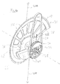
- FIG. 4 shows a perspective view of the slicing device according to FIG Fig. 1 .
- the sickle knife 10 and the toothed belt pulley 26 each have pockets or recesses 38, 40, whereby on the one hand the weight is reduced and on the other hand the mass distribution is specifically influenced.
- the vectors that illustrate the knife imbalance UM and the imbalances U1, U2 of the balancing masses 32, 34 are also drawn in.
- Fig. 5 shows the knife holder 20 with the sickle knife 10 removed.
- the knife holder 20 comprises screw holes 42 to which the sickle knife 10 is attached by means of screws 18 (cf. Fig. 1 ), and screw holes 54 at which the knife holder 20 is attached to the rotor shaft 12 on the front side.
- the radial displacement of the center of gravity of the knife holder 20 is achieved relatively far outward by an anchor-like or hammer-shaped design.
- the knife holder 20 can be compared to a hammer, that is, strongly top-heavy with radially outer head formed.
- the axial distance between the two balancing masses 32, 34 or the unbalances U1 and U2 is many times greater than the axial distance L1 between the first balancing mass 32 or its unbalance U1 and the cutting plane 14.
- the rotary drive 24 can be arranged in a housing which has a housing wall as a fixed frame or frame part which extends axially close to the rotary drive 24 perpendicular to the axis of rotation D on the side of the rotary drive 24 facing the knife 10.
- An axial drive L which is only indicated by a double arrow and is basically arbitrarily configured, can engage the rotor shaft 12 and be supported on this housing wall or at another point on the frame or frame.
- the axial drive L is activated.
- the sickle knife 10 together with the knife holder 20 as well as all balancing masses 32, 34 are adjusted together with the rotor shaft 12 relative to the housing wall or the frame or frame and relative to the rotor hub 22.
- the drive belt 28 is deflected slightly obliquely during this movement.
- the slicing device according to the invention is thus always perfectly balanced in all relevant planes and thus statically and dynamically, even with an axial movement of the knife 10.
- the arrangement according to the invention of the balancing masses 32, 34 also enables an extremely compact and thus space-saving construction of the rotor and the slicing device as a whole.
Landscapes
- Life Sciences & Earth Sciences (AREA)
- Forests & Forestry (AREA)
- Engineering & Computer Science (AREA)
- Mechanical Engineering (AREA)
- Food-Manufacturing Devices (AREA)
Abstract
Die Erfindung betrifft eine Vorrichtung zum Aufschneiden von Lebensmittelprodukten, insbesondere Hochleistungs-Slicer, mit zumindest einem um eine Drehachse rotierenden, eine Unwucht aufweisenden Schneidmesser, insbesondere Sichelmesser, einem Rotationsantrieb für das Schneidmesser, und einem zumindest eine Wuchtmasse umfassenden Gegengewicht zum Ausgleichen der Unwucht des Schneidmessers.The invention relates to a device for slicing food products, in particular high-performance slicers, with at least one unbalanced cutting knife rotating around an axis of rotation, in particular sickle-shaped knife, a rotary drive for the cutting knife, and a counterweight comprising at least one balancing mass to compensate for the unbalanced cutting knife .
Description
Die Erfindung betrifft eine Vorrichtung zum Aufschneiden von Lebensmittelprodukten, insbesondere Hochleistungs-Slicer, mit zumindest einem um eine Drehachse rotierenden, eine Unwucht aufweisenden Schneidmesser, einem Rotationsantrieb für das Schneidmesser, der auf einer Antriebsseite des Schneidmessers angeordnet ist, und einem zumindest eine Wuchtmasse umfassenden Gegengewicht zum Ausgleichen der Unwucht des Schneidmessers.The invention relates to a device for slicing food products, in particular a high-performance slicer, with at least one unbalanced cutting knife rotating around an axis of rotation, a rotary drive for the cutting knife which is arranged on a drive side of the cutting knife, and a counterweight comprising at least one balancing mass to compensate for the imbalance of the cutting knife.
Bei derartigen Aufschneidevorrichtungen, die auch als Slicer bezeichnet werden, können Sichelmesser zum Einsatz kommen, welche mit einer Drehzahl von rund 600 bis zu etwa 2.500 Umdrehungen pro Minute rotieren.With such slicing devices, which are also referred to as slicers, sickle knives can be used, which rotate at a speed of around 600 to around 2,500 revolutions per minute.
Das Aufschneiden der Produkte erfolgt bei einem Sichelmesser mithilfe der Geometrie des Messers. Eine planetarische Bewegung des Messers, wie beispielsweise bei einem Kreismesser, ist nicht notwendig.With a sickle knife, the products are cut using the geometry of the knife. A planetary movement of the knife, as for example with a circular knife, is not necessary.
Dazu weist das Sichelmesser eine gegenüber der Rotationsachse asymmetrische Kontur auf. Der Messerschwerpunkt, d.h. der Massenschwerpunkt des Messers, ist also gegenüber der Rotationsachse verschoben. Entsprechend der Messermasse, der Messerform und/oder der Messerkontur ergibt sich somit eine Unwucht mit einer bestimmten Unwuchtmasse bzw. Unwuchtlage. Um insbesondere bei den hohen auftretenden Drehzahlen einen vibrationsfreien Lauf des Messers zu gewährleisten, muss eine derartige Aufschneidevorrichtung in allen Ebenen ausgewuchtet sein.For this purpose, the sickle knife has a contour that is asymmetrical with respect to the axis of rotation. The center of gravity of the knife, ie the center of mass of the knife, is thus shifted relative to the axis of rotation. According to the knife mass, the knife shape and / or the knife contour, an imbalance with a certain imbalance mass or unbalance position results. In order to ensure a vibration-free run of the knife, especially at the high speeds that occur, such a cutting device must be balanced in all planes.
Es ist bekannt, Gegengewichte sowohl vor dem Messer als auch hinter dem Messer anzuordnen. Dadurch kann eine Wuchtung in einer radialen Ebene und in einer axialen Ebene gewährleistet werden. Ein Taumeln des Messers kann auf diese Weise unterdrückt werden.It is known to arrange counterweights both in front of the knife and behind the knife. Balancing in a radial plane and in an axial plane can thereby be ensured. In this way, wobbling of the knife can be suppressed.
Die
Nachteilig daran ist, dass ein in der Praxis häufig erforderliches Auswechseln des Messers eine Demontage der Gegengewichte erforderlich macht. Insbesondere das Gegengewicht, das sich vor dem Messer befindet, muss bei jedem Wechsel entfernt und anschließend wieder neu montiert werden. Dies ist mit einem erheblichen Zeitaufwand verbunden und somit unökonomisch und unergonomisch.The disadvantage of this is that replacement of the knife, which is often necessary in practice, makes it necessary to dismantle the counterweights. The counterweight in particular, which is located in front of the knife, has to be removed every time it is changed and then reassembled. This is associated with a considerable expenditure of time and is therefore uneconomical and unergonomic.
Die
Unter dem Begriff "Unwucht" ist im Folgenden auch allgemein je nach Zusammenhang eine Unwuchtmasse, eine Unwuchtlage und/oder eine bei der Rotation aufgrund der Unwuchtmasse wirksame Kraft hinsichtlich Betrag und Richtung zu verstehen.In the following, the term “unbalance” also generally means an unbalanced mass, an unbalanced position and / or an unbalanced mass, depending on the context to understand the rotation due to the unbalanced mass effective force in terms of magnitude and direction.
Axiale Abstände, also längs der Drehachse des Messers gemessene Abstände, relativ zu einem Schneidmesser beziehen sich hier, sofern nichts anderes angegeben ist, auf eine durch das Messer definierte Schneidebene, während sich die axiale Lage einer Wuchtmasse bzw. Unwucht auf eine Ebene bezieht, die senkrecht zur Drehachse des Messers verläuft und in der der Massenschwerpunkt der Wuchtmasse bzw. Unwucht liegt. Generell beziehen sich hier Angaben zur Lage oder Wirkungsrichtung einer Wuchtmasse, sofern nichts anderes angegeben ist, auch auf die durch die Wuchtmasse bzw. durch die Komponente oder Baugruppe, in welche die betreffende Wuchtmasse integriert ist, erzeugte Unwucht.Unless otherwise specified, axial distances, i.e. distances measured along the axis of rotation of the knife, relative to a cutting knife relate to a cutting plane defined by the knife, while the axial position of a balancing mass or imbalance relates to a plane that runs perpendicular to the axis of rotation of the knife and in which the center of gravity of the balance mass or imbalance lies. In general, information on the position or direction of action of a balancing mass also relate here, unless otherwise stated, to the imbalance generated by the balancing mass or by the component or assembly in which the balancing mass in question is integrated.
Wenn eine Integration einer Wuchtmasse in eine Komponente oder Baugruppe der Vorrichtung im Sinne eines gezielten Hinzufügens einer zusätzlichen Masse verstanden wird, dann ist für den Fachmann klar, dass dies gleichbedeutend ist mit einer gezielten Wegnahme von Material von einer Komponente oder Baugruppe, mathematisch gesprochen also mit einem gezielten Hinzufügen einer "negativen Wuchtmasse", allgemein also mit der gezielten Erzeugung einer Unwucht an oder in der betreffenden Komponente bzw. Baugruppe.If an integration of a balancing mass in a component or assembly of the device is understood in the sense of a targeted addition of an additional mass, then it is clear to the person skilled in the art that this is synonymous with a targeted removal of material from a component or assembly, mathematically speaking with a targeted addition of a "negative balancing mass", that is to say generally with the targeted generation of an imbalance on or in the relevant component or assembly.
Es ist eine Aufgabe der Erfindung, eine Unwucht eines Schneidmessers einer Aufschneidevorrichtung auf einfache und kostengünstige Weise auszugleichen, wobei insbesondere die Handhabung der Vorrichtung in hygienischer Hinsicht besonders günstig sein soll.It is an object of the invention to compensate for an imbalance in a cutting knife of a slicing device in a simple and inexpensive manner, the handling of the device in particular being particularly favorable from a hygienic point of view.
Die Lösung dieser Aufgabe erfolgt durch eine Vorrichtung mit den jeweiligen Merkmalen der unabhängigen Ansprüche. Die Erfindung umfasst mehrere unabhängige Aspekte gemäß den unabhängigen Ansprüchen, die nachstehend näher erläutert und die im Rahmen der Erfindung grundsätzlich auch beliebig miteinander kombinierbar sind. Für Kombinationen dieser Aspekte wird ebenfalls Schutz beansprucht.This object is achieved by a device with the respective features of the independent claims. The invention includes several independent aspects according to the independent claims, which are explained in more detail below and which can in principle also be combined with one another as required within the scope of the invention. Protection is also claimed for combinations of these aspects.
Gemäß einem Aspekt der Erfindung ist das Gegengewicht ausschließlich auf einer Seite des Schneidmessers angeordnet.According to one aspect of the invention, the counterweight is arranged exclusively on one side of the cutting knife.
Insbesondere sind erfindungsgemäß alle Wuchtmassen nur auf einer Seite des Schneidmessers angeordnet, d.h. die Erfindung bedeutet eine Abkehr von aus dem Stand der Technik bekannten Wuchtkonzepten, bei denen das Gegengewicht auf beide Messerseiten aufgeteilt, also zumindest eine Wuchtmasse vor und wenigstens eine weitere Wuchtmasse hinter dem Messer angeordnet ist. Auf die Vorteile, die sich aus dem erfindungsgemäßen Wuchtkonzept ergeben, wird nachstehend näher eingegangen.In particular, according to the invention, all balancing masses are only arranged on one side of the cutting knife, i.e. the invention means a departure from balancing concepts known from the prior art in which the counterweight is divided between both knife sides, that is, at least one balancing mass is arranged in front of and at least one further balancing mass is arranged behind the knife. The advantages resulting from the balancing concept according to the invention will be discussed in greater detail below.
In Abhängigkeit von dem jeweiligen Slicerkonzept kann die Seite, auf der sich das Gegengewicht befindet, die Antriebsseite des Messers sein. Dies ist aber nicht zwingend. Die Seite des Gegengewichts kann auch die Messerseite sein, von der aus die Produkte dem Messer zugeführt werden. Diese Zuführseite kann je nach Aufbau des jeweiligen Slicers mit der Antriebsseite identisch sein, wobei dies aber nicht zwingend ist. Insbesondere ist erfindungsgemäß vorgesehen, dass sich alle Wuchtmassen nicht auf der Seite des Messers befinden, die für eine Demontage des Messers vorgesehen ist, d.h. von der Demontageseite des Messers aus gesehen befinden sich alle Wuchtmassen auf der anderen Seite des Messers. Wenn das Messer z.B. nach vorne abgenommen werden muss, befinden sich alle Wuchtmassen hinter dem Messer, so dass für eine Demontage des Messers keine Wuchtmasse bewegt zu werden braucht.Depending on the respective slicer concept, the side on which the counterweight is located can be the drive side of the knife. But this is not mandatory. The side of the counterweight can also be the knife side from which the products are fed to the knife. Depending on the structure of the respective slicer, this feed side can be identical to the drive side, although this is not mandatory. In particular, it is provided according to the invention that all balancing masses are not located on the side of the knife which is intended for dismantling the knife, ie, viewed from the dismantling side of the knife, all balancing masses are on the other side of the knife. If the knife has to be removed forwards, for example, all the balancing masses are located behind the knife, so that no balancing mass has to be moved to dismantle the knife.
Auf der Demontageseite des Messers ist somit keine Wuchtmasse vorgesehen. Gegebenenfalls auf dieser Seite befindliche Bauteile, beispielsweise ein Teil einer Nabe oder Befestigungsmittel, z.B. Schrauben, dienen hierbei lediglich der Befestigung des Schneidmessers oder anderen Zwecken, nicht aber dem Ausgleichen der Unwucht des Schneidmessers. Die wuchtmassenfreie Seite des Messers, insbesondere also die Demontageseite, kann mit der Seite identisch sein, auf der die aufgeschnittenen Produkte abtransportiert werden, wobei dies aber nicht zwingend und von dem jeweiligen Slicer-Konzept abhängig ist. Es existieren Slicer-Konzepte, bei denen die Antriebsseite und die Demontageseite des Messers auf der gleichen Messerseite und somit gegenüber der Produktzuführseite liegen.No balancing mass is therefore provided on the dismantling side of the knife. Any components located on this side, for example part of a hub or fastening means, e.g. Screws are only used to fasten the cutting knife or for other purposes, but not to compensate for the imbalance of the cutting knife. The side of the knife free from balancing masses, in particular the dismantling side, can be identical to the side on which the cut products are transported away, although this is not mandatory and depends on the respective slicer concept. There are slicer concepts in which the drive side and the dismantling side of the knife are on the same knife side and thus opposite the product feed side.
Dadurch, dass hierbei auf einer Seite der Schneidebene - also insbesondere auf der Demontageseite des Schneidmessers - kein Gegengewicht benötigt wird, müssen zur Demontage des Messers keine als Unwuchtmassen dienenden Bauteile aufwändig, beispielsweise durch den Einsatz von Werkzeugen, entfernt werden. Die Stillstandzeiten, z.B. aufgrund von Wartungsarbeiten, werden somit deutlich reduziert, wodurch Kosten gespart werden können.Since no counterweight is required on one side of the cutting plane - i.e. in particular on the dismantling side of the cutting knife - no components serving as unbalanced masses have to be removed in a complex manner, for example by using tools, to dismantle the knife. The downtimes, e.g. due to maintenance work, are thus significantly reduced, which means that costs can be saved.
Generell ist das Gegengewicht an die Messermasse bzw. Messerform, welche die Unwucht des Schneidmessers bestimmt, angepasst.In general, the counterweight is adapted to the knife mass or knife shape, which determines the imbalance of the cutting knife.
Darüber hinaus ermöglicht oder erleichtert die erfindungsgemäße vollständige Anordnung des Gegengewichts, also aller vorgesehenen Wuchtmassen, nur auf einer Seite des Messers besonders vorteilhafte Wuchtkonzepte, auf die nachstehend in Verbindung mit weiteren unabhängigen Aspekten der Erfindung näher eingegangen wird.In addition, the complete arrangement of the counterweight according to the invention, i.e. all the balancing masses provided, enables or facilitates particularly advantageous balancing concepts only on one side of the knife, which are discussed in more detail below in connection with further independent aspects of the invention.
Gemäß einem Aspekt der Erfindung ist das Schneidmesser abnehmbar an einer Messeraufnahme angebracht. Die Messeraufnahme bildet eine Wuchtmasse und weist bezüglich der Drehachse eine asymmetrische Rotationsgeometrie auf.According to one aspect of the invention, the cutting knife is removably attached to a knife holder. The knife holder forms a balancing mass and has an asymmetrical rotational geometry with respect to the axis of rotation.
Hierbei ist es die Messeraufnahme selbst, die eine zum Auswuchten des Messers dienende Wuchtmasse bildet. Dieses Konzept ermöglicht es, die benötigte Wuchtmasse einerseits axial nahe am Messer und andererseits radial relativ weit außen zu positionieren, was insgesamt ein besonders effizientes Wuchtkonzept realisierbar macht. Durch die asymmetrische Ausbildung der Messeraufnahme kann bei relativ geringem Gesamtgewicht der Messeraufnahme eine ausreichend große Unwucht erzeugt werden.In this case, it is the knife holder itself that forms a balancing mass used to balance the knife. This concept makes it possible to position the required balancing mass on the one hand axially close to the knife and on the other hand relatively far outside in the radial direction, which makes a particularly efficient balancing concept possible overall. Due to the asymmetrical design of the knife holder, a sufficiently large imbalance can be generated with a relatively low total weight of the knife holder.
Diese bezüglich der Drehachse asymmetrische Form der Messeraufnahme bedeutet eine Abkehr von aus dem Stand der Technik bekannten Konzepten für die Messeraufnahme, bei denen es entscheidend darauf ankommt, eine Messeraufnahme mit einer bezüglich der Drehachse symmetrischen Rotationsgeometrie, insbesondere mit einer zur Drehachse konzentrischen kreisförmigen Außenkontur zu versehen, die benötigt wird, um eine entsprechend kreisförmige Öffnung in einem Gehäuse oder Gestell des Slicers abzudichten bzw. mit dieser Öffnung einen engen Ringspalt zu bilden.This shape of the knife holder, which is asymmetrical with respect to the axis of rotation, means a departure from concepts known from the prior art for the knife holder, in which it is crucial to provide a knife holder with a rotational geometry that is symmetrical with respect to the axis of rotation, in particular with a circular outer contour concentric to the axis of rotation , which is required to seal a correspondingly circular opening in a housing or frame of the slicer or to form a narrow annular gap with this opening.
Zugunsten einer möglichst weit radial außen liegenden Wuchtmasse kann erfindungsgemäß die Messeraufnahme von einer kreisförmigen Außenkontur extrem abweichen und gewissermaßen stark kopflastig - bezogen auf die radiale Richtung - ausgebildet werden, d.h. mit einer relativ großen Unwucht bzw. Unwuchtmasse behaftet sein, beispielsweise - bildlich gesprochen - wie ein rotierender Hammer.In favor of a balancing mass lying as far radially outward as possible, the knife holder can, according to the invention, deviate extremely from a circular outer contour and, to a certain extent, be very top-heavy - based on the radial direction - that is, have a relatively large imbalance or imbalance mass, for example - figuratively speaking - like a rotating hammer.
Dabei kann die Messeraufnahme z.B. einen ersten Abschnitt und einen zweiten Abschnitt umfassen, wobei der erste Abschnitt den größten Radius der Messeraufnahme bildet, die Drehachse durch den zweiten Abschnitt hindurch verläuft, und der Massenschwerpunkt des ersten Abschnitts radial weiter außen als der Massenschwerpunkt des zweiten Abschnitts liegt. Insgesamt kann die Messeraufnahme z.B. zumindest näherungsweise nach Art eines Ankers geformt sein, wobei ein relativ schwerer Kreisringabschnitt radial außen an einem vergleichsweise leichten Zentralabschnitt, durch den die Drehachse verläuft, angeordnet ist. Je nach Größe der benötigten Unwucht kann sich der äußere Kreisringabschnitt beispielsweise über mindestens 1/7, 1/6, 1/5, 1/4 oder 1/3 des Außenumfangs der Messeraufnahme erstrecken.The knife holder can e.g. comprise a first section and a second section, wherein the first section forms the largest radius of the knife holder, the axis of rotation extends through the second section, and the center of mass of the first section is located radially further out than the center of mass of the second section. Overall, the knife holder can e.g. be shaped at least approximately in the manner of an anchor, a relatively heavy circular ring section being arranged radially on the outside on a comparatively light central section through which the axis of rotation runs. Depending on the size of the imbalance required, the outer circular ring section can extend, for example, over at least 1/7, 1/6, 1/5, 1/4 or 1/3 of the outer circumference of the knife holder.
Dadurch, dass die Messeraufnahme selbst eine Wuchtmasse bildet, gestaltet sich die Konstruktion besonders einfach. Die Wuchtmasse befindet sich außerdem auf diese Weise axial besonders nahe an der Schneidebene. Eine weitere, separate Wuchtmasse in axialer Nähe des Schneidmessers ist somit nicht notwendig. Die Messeraufnahme erfüllt also eine Doppelfunktion, da sie einerseits das Messer trägt und andererseits zumindest einen Teil der Unwucht des Schneidmessers ausgleicht.Because the knife holder itself forms a balancing mass, the construction is particularly simple. In this way, the balancing mass is also particularly close to the cutting plane axially. A further, separate balancing mass in the axial vicinity of the cutting knife is therefore not necessary. The knife holder thus fulfills a double function, since on the one hand it carries the knife and on the other hand it compensates for at least part of the imbalance of the cutting knife.
Bei einem Austausch eines Messers durch ein Messer mit einem anderen Durchmesser und damit einer anderen Unwucht braucht lediglich die Messeraufnahme ausgetauscht zu werden. Die Aufschneidevorrichtung ist somit besonders einfach an verschiedene Anwendungen anpassbar. Auf einfache Weise können dadurch Messer mit unterschiedlichen Größen eingesetzt werden.When a knife is exchanged for a knife with a different diameter and thus a different imbalance, only the knife holder needs to be replaced. The slicing device can thus be adapted particularly easily to different applications. Knives of different sizes can thus be used in a simple manner.
Dadurch, dass lediglich die Messeraufnahme ausgetauscht werden muss, können die weiteren Komponenten der Aufschneidevorrichtung beibehalten werden. Insbesondere kann eine gegebenenfalls zusätzlich vorgesehene weitere Wuchtmasse in derselben Position verbleiben.Because only the knife holder has to be exchanged, the other components of the slicing device can be retained become. In particular, a possibly additionally provided further balancing mass can remain in the same position.
Gemäß einem Aspekt der Erfindung ist die Wuchtmasse oder eine der Wuchtmassen von dem Rotationsantrieb gebildet, insbesondere von einer Antriebsscheibe oder von einer Nabe, die mittels eines Antriebsmotors über einen Antriebsriemen in Rotation versetzbar ist.According to one aspect of the invention, the balancing mass or one of the balancing masses is formed by the rotary drive, in particular by a drive pulley or a hub that can be set in rotation by means of a drive motor via a drive belt.
Auf diese Weise erfüllt der Rotationsantrieb eine Doppelfunktion, da er einerseits das Schneidmesser in Rotation versetzt und andererseits zumindest einen Teil der Unwucht des Schneidmessers ausgleicht.In this way, the rotary drive fulfills a double function, since on the one hand it sets the cutting knife in rotation and, on the other hand, it compensates at least part of the imbalance of the cutting knife.
Anders ausgedrückt bildet gemäß einem Aspekt der Erfindung der Rotationsantrieb aufgrund der Wuchtmasse bzw. der Unwucht zusammen mit dem Schneidmesser ein Massensystem, das derart hinsichtlich Dimensionierung und Anordnung ausgelegt werden kann, dass sich der Gesamtschwerpunkt des rotierenden Systems auf derjenigen Seite des Schneidmessers befindet, auf der auch der Rotationsantrieb gelegen ist. Mit anderen Worten wird dieser Schwerpunkt durch die Unwucht im Rotationsantrieb auf dessen Seite "gezogen". Folglich ist es möglich, eine weitere Wuchtmasse ebenfalls auf dieser Seite des Schneidmessers anzuordnen, so dass sich alle Wuchtmassen nur auf einer Seite des Schneidmessers befinden. Indem man hierdurch den Gesamtschwerpunkt auf die Seite des Rotationsantriebs "wandern" lässt, ist es nicht mehr erforderlich, Wuchtmassen auf beiden Seiten des Messers bzw. der Unwucht des Messers anzuordnen.In other words, according to one aspect of the invention, the rotary drive due to the balancing mass or the imbalance together with the cutting knife forms a mass system that can be designed in terms of dimensioning and arrangement such that the overall center of gravity of the rotating system is on that side of the cutting knife on which the rotary drive is also located. In other words, this center of gravity is "pulled" to its side by the imbalance in the rotary drive. Consequently, it is possible to also arrange a further balancing mass on this side of the cutting knife, so that all balancing masses are only on one side of the cutting knife. By allowing the overall center of gravity to "wander" to the side of the rotary drive, it is no longer necessary to arrange balancing masses on both sides of the knife or the imbalance of the knife.
Bezogen auf die axiale Länge der Gesamtanordnung - gemessen zwischen Schneidebene und Ebene des Rotationsantriebs - kann die Wuchtmasse des Rotationsantriebs in großer axialer Entfernung von der Schneidebene angeordnet werden. Hieraus resultiert sozusagen eine relativ große Hebelwirkung der Wuchtmasse, die damit selbst nur ein vergleichsweise geringes Gewicht aufzuweisen braucht, was wiederum in der Praxis ihre Integration in den Rotationsantrieb erleichtert oder überhaupt erst ermöglicht.In relation to the axial length of the overall arrangement - measured between the cutting plane and the plane of the rotary drive - the balancing mass of the rotary drive can be at a large axial distance from the cutting plane to be ordered. This results, so to speak, in a relatively large leverage effect of the balancing mass, which therefore only needs to have a comparatively low weight, which in turn facilitates its integration into the rotary drive or even enables it in the first place.
In Kombination mit einer von der Messeraufnahme gebildeten und somit axial extrem nahe an der Schneidebene befindlichen Wuchtmasse kann die von dem Rotationsantrieb gebildete Wuchtmasse eine optimale Auswuchtung des rotierenden Gesamtsystems in allen Ebenen und sowohl statisch als auch dynamisch bewirken, und dies bei einem äußerst kompakten Aufbau der Gesamtanordnung.In combination with a balancing mass formed by the knife holder and thus located axially extremely close to the cutting plane, the balancing mass formed by the rotary drive can bring about optimal balancing of the entire rotating system in all planes, both statically and dynamically, and this with an extremely compact design of the Overall arrangement.
Ein weiterer Vorteil ist, dass durch Modifizieren des Rotationsantriebs, beispielsweise durch einen Austausch der Antriebsscheibe oder der Nabe, ein Messer mit einer anderen Größe und somit einer anderen Unwucht ausgewuchtet werden kann. Eine gegebenenfalls zusätzlich zum Rotationsantrieb als Wuchtmasse dienende Messeraufnahme selbst muss dabei nicht zwingend ausgetauscht werden, wobei es aber möglich ist, bei einem Messerwechsel sowohl die Messeraufnahme als auch die Antriebsscheibe bzw. die Nabe zu wechseln, letzteres insbesondere dann, wenn es nicht möglich oder nicht gewünscht ist, die mit einem Messerwechsel verbundene Änderung der auszugleichenden Unwucht ausschließlich durch Austauschen der Messeraufnahme zu kompensieren.Another advantage is that by modifying the rotary drive, for example by replacing the drive pulley or the hub, a knife with a different size and thus a different imbalance can be balanced. A knife holder itself, which may serve as a balancing mass in addition to the rotary drive, does not necessarily have to be exchanged, but it is possible to change both the knife holder and the drive disk or hub when changing a knife, the latter in particular if this is not possible or not it is desired to compensate for the change in the imbalance to be compensated associated with a knife change exclusively by exchanging the knife holder.
Bei der Antriebsscheibe kann es sich beispielsweise um eine Zahnriemenscheibe handeln, welche über einen motorgetriebenen Zahnriemen in eine Drehbewegung versetzt wird. Die Antriebsscheibe kann z.B. eine Welle antreiben, welche die Messeraufnahme und somit das Messer trägt und in Rotation versetzt und welche in einer feststehenden Nabe drehbar gelagert ist. Alternativ kann anstelle einer Antriebsscheibe eine insbesondere hohlzylindrische Nabe vorgesehen sein, die z.B. über einen motorgetriebenen Zahnriemen in eine Drehbewegung versetzt wird und die die Messeraufnahme und somit das Messer trägt und in Rotation versetzt, wobei die Nabe auf einer Welle oder Spindel drehbar gelagert ist, welche selbst relativ zum Messer drehbar ist. Die angetriebene Welle oder die angetriebene Nabe kann die als separates Bauteil ausgebildete Messeraufnahme tragen oder selbst als Messeraufnahme ausgebildet sein. Wenn eine drehangetriebene Nabe gleichzeitig als Messeraufnahme ausgebildet ist, kann die Nabe an zumindest zwei axial beabstandeten Stellen jeweils eine Wuchtmasse beinhalten bzw. als Unwucht wirken, um die Unwucht des Messers auszugleichen. Das von den Unwuchtmassen bzw. den Unwuchten gebildete Gegengewicht wird dabei von einer einzigen Komponente - nämlich der einerseits drehangetriebenen und andererseits das mit der auszugleichenden Unwucht behaftete Messer tragenden Nabe - bereitgestellt, die auf einer Seite des Messers angeordnet ist, so dass auch in dieser Variante alle zum Ausgleichen der Messerunwucht vorgesehenen Wuchtmassen bzw. Unwuchten nur auf einer Seite des Messers angeordnet zu werden brauchen.The drive pulley can be, for example, a toothed belt pulley which is set in rotary motion by a motor-driven toothed belt. The drive pulley can, for example, drive a shaft which carries the knife holder and thus the knife and is set in rotation and which is rotatably mounted in a stationary hub. Alternatively, instead of a drive pulley, a particularly hollow cylindrical one Hub can be provided, which is set in rotation, for example via a motor-driven toothed belt, and which carries the knife holder and thus the knife and sets it in rotation, the hub being rotatably mounted on a shaft or spindle which is itself rotatable relative to the knife. The driven shaft or the driven hub can carry the knife holder designed as a separate component or can itself be designed as a knife holder. If a rotationally driven hub is designed as a knife holder at the same time, the hub can each contain a balancing mass at at least two axially spaced locations or act as an imbalance in order to compensate for the imbalance of the knife. The counterweight formed by the imbalance masses or the imbalances is provided by a single component - namely the hub that is rotationally driven on the one hand and the hub carrying the knife that is affected by the imbalance on the other hand - which is arranged on one side of the knife, so that in this variant all of the balancing masses or imbalances provided to compensate for the knife imbalance only need to be arranged on one side of the knife.
Der Rotationsantrieb ist insbesondere axial vom Schneidmesser beabstandet, und zwar beispielsweise in einem Bereich zwischen 150 mm und 500 mm, bevorzugt von 150 mm bis 300 mm.The rotary drive is in particular axially spaced from the cutting knife, for example in a range between 150 mm and 500 mm, preferably from 150 mm to 300 mm.
Bei allen hier erwähnten Aspekten der Erfindung ist insbesondere vorgesehen, dass das Gegengewicht nicht lediglich eine einzige Wuchtmasse, sondern mehrere axial voneinander beabstandete Wuchtmassen umfasst. Insbesondere sind genau zwei Wuchtmassen vorgesehen. In einer besonders bevorzugten Ausgestaltung ist vorgesehen, eine Wuchtmasse axial nahe am Messer, beispielsweise in Form einer entsprechend asymmetrisch ausgebildeten Messeraufnahme, anzuordnen und eine weitere Wuchtmasse in größerer axialer Entfernung vom Messer, beispielsweise im Rotationsantrieb oder als Bestandteil des Rotationsantriebs, zu positionieren.In all of the aspects of the invention mentioned here, it is provided in particular that the counterweight does not just comprise a single balancing mass, but rather several balancing masses that are axially spaced from one another. In particular, exactly two balancing masses are provided. In a particularly preferred embodiment, provision is made for a balancing mass to be arranged axially close to the knife, for example in the form of a correspondingly asymmetrically designed knife holder, and a further balancing mass to be positioned at a greater axial distance from the knife, for example in the rotary drive or as part of the rotary drive.
Das Konzept mehrerer, insbesondere zweier, Wuchtmassen zusätzlich zu der Unwucht des Messers kann sich bei entsprechender Dimensionierung und Anordnung der Wuchtmassen in Abhängigkeit von der Messerunwucht in vorteilhafter Weise den Umstand zunutze machen, dass der Schwerpunkt der Unwucht einerseits sowie die Schwerpunkte der einzelnen Wuchtmassen andererseits stets zu einem gemeinsamen Schwerpunkt des gesamten rotierenden Systems streben.The concept of several, especially two, balancing masses in addition to the imbalance of the knife can, with appropriate dimensioning and arrangement of the balancing masses depending on the knife imbalance, advantageously make use of the fact that the center of gravity of the imbalance on the one hand and the centers of gravity of the individual balancing masses on the other hand strive for a common focus of the entire rotating system.
Gemäß einem Aspekt der Erfindung ist zum Ausgleichen der Unwucht des Schneidmessers ein Gegengewicht vorgesehen, das zumindest zwei axial voneinander beabstandete Wuchtmassen umfasst. Eine erste Wuchtmasse und die Unwucht des Schneidmessers sind zumindest näherungsweise in entgegengesetzte radiale Richtungen wirksam, während eine zweite Wuchtmasse zumindest näherungsweise in die gleiche radiale Richtung wirksam ist wie die Unwucht des Schneidmessers. Dabei ist die erste Wuchtmasse in axialer Richtung näher am Schneidmesser angeordnet als die zweite Wuchtmasse.According to one aspect of the invention, a counterweight is provided to compensate for the imbalance of the cutting knife, which counterweight comprises at least two axially spaced apart balancing masses. A first balancing mass and the unbalance of the cutting knife are effective at least approximately in opposite radial directions, while a second balancing mass is effective at least approximately in the same radial direction as the unbalance of the cutting knife. The first balancing mass is arranged closer to the cutting knife in the axial direction than the second balancing mass.
Durch die geometrische Anordnung der Wuchtmassen kann ein in allen Ebenen und sowohl statisch als auch dynamisch ausgewuchtetes System auch bei einem vergleichsweise kompakt und relativ einfach aufgebauten Slicer realisiert werden.Due to the geometric arrangement of the balancing masses, a system that is balanced in all planes, both statically and dynamically, can also be implemented with a comparatively compact and relatively simply constructed slicer.
Weiterbildungen der Erfindung sind auch den abhängigen Ansprüchen, der Beschreibung sowie den beigefügten Zeichnungen zu entnehmen. Nach einer Ausführungsform ist eine erste Wuchtmasse in einem axialen Abstand vom Schneidmesser angeordnet, der um ein Vielfaches kleiner ist als der axiale Abstand einer zweiten Wuchtmasse vom Schneidmesser.Further developments of the invention can also be found in the dependent claims, the description and the accompanying drawings. According to one embodiment, a first balancing mass is arranged at an axial distance from the cutting knife which is many times smaller than the axial distance between a second balancing mass and the cutting knife.
Die erste Wuchtmasse befindet sich insbesondere sehr nahe am Schneidmesser und kann z.B. in eine Messeraufnahme integriert sein, ein Bestandteil der Messeraufnahme sein oder von der Messeraufnahme gebildet sein.The first balancing mass is in particular very close to the cutting knife and can e.g. be integrated into a knife holder, be part of the knife holder or be formed by the knife holder.
Durch einen vergleichsweise großen axialen Abstand der zweiten Wuchtmasse vom Schneidmesser kann aufgrund der dadurch vorhandenen relativ großen Hebelwirkung die zweite Wuchtmasse relativ klein gewählt werden. Dadurch braucht nur eine geringe Masse beschleunigt bzw. in Rotation versetzt zu werden.Due to a comparatively large axial distance between the second balancing mass and the cutting knife, the second balancing mass can be selected to be relatively small due to the relatively great leverage that this creates. As a result, only a small mass needs to be accelerated or set in rotation.
Nach einer weiteren Ausführungsform ist eine erste Wuchtmasse (bzw. deren Unwucht bzw. die Unwucht einer die erste Wuchtmasse umfassenden Komponente oder Baugruppe) in einem axialen Abstand von maximal 50 mm, 40 mm, 35 mm, 30 mm oder 25 mm, vorzugsweise von maximal 20 mm, vom Schneidmesser angeordnet. Eine zweite Wuchtmasse (bzw. deren Unwucht bzw. die Unwucht einer die zweite Wuchtmasse umfassenden Komponente oder Baugruppe) ist in einem axialen Abstand von 100 mm bis 2.000 mm, insbesondere von 150 mm bis 500 mm, insbesondere bevorzugt von 150 mm bis 300 mm, vom Schneidmesser angeordnet.According to a further embodiment, a first balancing mass (or its imbalance or the imbalance of a component or assembly comprising the first balancing mass) is at an axial distance of a maximum of 50 mm, 40 mm, 35 mm, 30 mm or 25 mm, preferably a maximum 20 mm, arranged from the cutting knife. A second balancing mass (or its imbalance or the imbalance of a component or assembly comprising the second balancing mass) is at an axial distance of 100 mm to 2,000 mm, in particular from 150 mm to 500 mm, particularly preferably from 150 mm to 300 mm, arranged by the cutting knife.
Der Abstand zwischen der ersten Wuchtmasse und der zweiten Wuchtmasse kann beispielsweise mindestens 50 mm, 75 mm, 100 mm, 150 mm, 200 mm, 300 mm, 500 mm, 1.000 mm, 1.500 mm oder 2.000 mm betragen.The distance between the first balancing mass and the second balancing mass can for example be at least 50 mm, 75 mm, 100 mm, 150 mm, 200 mm, 300 mm, 500 mm, 1,000 mm, 1,500 mm or 2,000 mm.
Gemäß einer weiteren Ausführungsform ist eine erste Wuchtmasse bzw. deren Unwucht größer als die Unwucht des Schneidmessers. Insbesondere ist die Summe aus der Unwucht des Schneidmessers und einer zweiten Wuchtmasse bzw. deren Unwucht gleich oder annähernd gleich der ersten Wuchtmasse bzw. deren Unwucht.According to a further embodiment, a first balancing mass or its imbalance is greater than the imbalance of the cutting knife. In particular, the sum of the imbalance of the cutting knife and a second balancing mass or its imbalance is equal to or approximately equal to the first balancing mass or its imbalance.
Nach einer weiteren Ausführungsform reicht eine erste Wuchtmasse bis zu einem radialen Abstand von der Drehachse, der zumindest 75 %, insbesondere 90 % und bevorzugt zumindest näherungsweise 100 % des kleinsten Radius des Schneidmessers beträgt, wobei insbesondere die erste Wuchtmasse in axialer Richtung näher am Schneidmesser angeordnet ist als eine zweite Wuchtmasse.According to a further embodiment, a first balancing mass extends up to a radial distance from the axis of rotation which is at least 75%, in particular 90% and preferably at least approximately 100% of the smallest radius of the cutting knife, in particular the first balancing mass being arranged closer to the cutting knife in the axial direction is as a second balancing mass.
Gemäß einer weiteren Ausführungsform beträgt der größte Radius der Messeraufnahme zumindest 75 %, insbesondere 90 % und bevorzugt zumindest näherungsweise 100 % des kleinsten Radius des Schneidmessers. Erfindungsgemäß kann die Messeraufnahme folglich zumindest in einem Teilbereich ihres Umfangs in radialer Richtung bis zum kleinsten Radius des Schneidmessers reichen, was bei aus dem Stand der Technik bekannten Anordnungen aufgrund eines von der Erfindung grundverschiedenen Gesamtkonzepts unmöglich ist. Dies ist z.B. dann der Fall, wenn die Messeraufnahme eine vergleichsweise kleine Gehäuse- bzw. Gestellöffnung zu schließen hat und deshalb eine Kreisform mit einem relativ kleinen Radius aufweisen muss, oder wenn das Messer eine vergleichsweise große Öffnung zur Anbringung der Messeraufnahme aufweist.According to a further embodiment, the largest radius of the knife holder is at least 75%, in particular 90% and preferably at least approximately 100% of the smallest radius of the cutting knife. According to the invention, the knife holder can consequently extend at least in a partial area of its circumference in the radial direction to the smallest radius of the cutting knife, which is impossible with arrangements known from the prior art due to an overall concept that is fundamentally different from the invention. This is e.g. then the case when the knife holder has to close a comparatively small housing or frame opening and must therefore have a circular shape with a relatively small radius, or when the knife has a comparatively large opening for attaching the knife holder.
Die erste Wuchtmasse befindet sich auf diese Weise radial relativ weit außen, d.h. ist relativ weit von der Drehachse des Schneidmessers beabstandet. Hierdurch kann die erste Wuchtmasse vergleichsweise klein ausgeführt werden. Dies wiederum ermöglicht es, die erste Wuchtmasse in axialer Richtung vergleichsweise nahe an der Unwucht des Messers und somit nahe an der Schneidebene zu platzieren. Auf diese Weise kann auch eine zweite Wuchtmasse vergleichsweise klein gewählt werden, und dies insbesondere umso mehr, je weiter die zweite Wuchtmasse axial vom Schneidmesser entfernt ist.In this way, the first balancing mass is located radially relatively far outside, that is, it is spaced relatively far from the axis of rotation of the cutting blade. As a result, the first balancing mass can be made comparatively small become. This in turn makes it possible to place the first balancing mass in the axial direction comparatively close to the unbalance of the knife and thus close to the cutting plane. In this way, a second balancing mass can also be selected to be comparatively small, and this in particular the more the further the second balancing mass is axially away from the cutting knife.
Durch eine solche Anordnung der Wuchtmassen müssen also nur relativ geringe Massen bewegt werden. Dies ist sowohl für die Drehbewegung des Messers als auch für eine gegebenenfalls während des Rotationsbetriebs erforderliche axiale Messerbewegung, insbesondere für eine getaktete Axialbewegung zur Durchführung von Leerschnitten, besonders vorteilhaft. Dadurch können auch die Dimensionierung und die Regelung der Dreh- und Axialantriebe optimiert werden.Such an arrangement of the balancing masses means that only relatively small masses have to be moved. This is particularly advantageous both for the rotary movement of the knife and for an axial knife movement that may be required during the rotary operation, in particular for a clocked axial movement for performing blank cuts. This also allows the dimensioning and control of the rotary and axial drives to be optimized.
In konstruktiver Hinsicht lässt sich ein solches Wuchtkonzept gemäß einer bevorzugten Ausführungsform der Erfindung auf besonders einfache und dennoch effektive Weise realisieren, indem die erste Wuchtmasse von einer Messeraufnahme und die zweite Wuchtmasse von dem Rotationsantrieb des Messers gebildet wird.In terms of construction, such a balancing concept can be implemented in a particularly simple and yet effective manner according to a preferred embodiment of the invention, in that the first balancing mass is formed by a knife holder and the second balancing mass by the rotary drive of the knife.
Gemäß einer weiteren Ausführungsform sind eine Messeraufnahme und der Rotationsantrieb auf unterschiedlichen Seiten eines feststehenden Gestell- oder Rahmenteils angeordnet. Das Gestell- oder Rahmenteil dient insbesondere zur axial beabstandeten Befestigung der Messeraufnahme über eine Nabe, durch die eine sich vom Rotationsantrieb zur Messeraufnahme erstreckende Antriebswelle hindurchgeführt ist.According to a further embodiment, a knife holder and the rotary drive are arranged on different sides of a stationary frame or frame part. The frame or frame part serves in particular for the axially spaced fastening of the knife holder via a hub through which a drive shaft extending from the rotary drive to the knife holder is passed.
In einer möglichen Weiterbildung ist die Messeraufnahme folglich von dem Gestell- oder Rahmenteil in axialer Richtung beabstandet. Auf diese Weise ist ein Zwischenraum zwischen der Messeraufnahme und dem Gestell- oder Rahmenteil vorhanden.In a possible further development, the knife receptacle is consequently spaced apart from the frame or frame part in the axial direction. In this way there is a gap between the knife holder and the frame or frame part.
Nach einer weiteren Ausführungsform sind eine erste Wuchtmasse und eine zweite Wuchtmasse auf unterschiedlichen Seiten eines feststehenden Gestell- oder Rahmenteils angeordnet.According to a further embodiment, a first balancing mass and a second balancing mass are arranged on different sides of a stationary frame or frame part.
Gemäß einer weiteren Ausführungsform bildet das Gestell- oder Rahmenteil zumindest einen Teil einer zum Schneidmesser weisenden Außenwand eines Antriebsgehäuses für den Rotationsantrieb.According to a further embodiment, the frame or frame part forms at least part of an outer wall of a drive housing for the rotary drive that faces the cutting knife.
Die vorstehend so bezeichnete "zweite Wuchtmasse", die axial weiter vom Schneidmesser entfernt gelegen ist als die andere Wuchtmasse, ist vorzugsweise in einem hygienisch unkritischen Bereich angeordnet, beispielsweise in einem Antriebsgehäuse.The "second balancing mass" referred to above, which is located axially further away from the cutting knife than the other balancing mass, is preferably arranged in a hygienically uncritical area, for example in a drive housing.
Vorzugsweise ist die erfindungsgemäße Vorrichtung derart ausgebildet, dass eine so genannte Feinwuchtung durchgeführt werden kann, um das System zu exakt wie möglich wuchten zu können. Die Feinwuchtung kann z.B. durch Hinzufügen oder Wegnehmen kleiner Gewichte erfolgen, insbesondere an oder im Bereich zumindest einer ohnehin vorgesehenen Wuchtmasse.The device according to the invention is preferably designed such that what is known as fine balancing can be carried out in order to be able to balance the system as precisely as possible. The fine balancing can e.g. by adding or removing small weights, in particular on or in the area of at least one balancing mass that is provided anyway.
Während bislang eine Feinwuchtung stets in der Nähe des Schneidmessers durchgeführt wurde, wird gemäß einer bevorzugten Weiterbildung der Erfindung vorgeschlagen, im Fall des Vorsehens zweier Wuchtmassen die Feinwuchtung an oder im Bereich der axial weiter vom Schneidmesser entfernt gelegenen Wuchtmasse vorzunehmen, bei der es sich insbesondere um die vorstehend als "zweite Wuchtmasse" bezeichnete Wuchtmasse handelt.While fine balancing has hitherto always been carried out in the vicinity of the cutting knife, according to a preferred development of the invention, in the case of providing two balancing masses, fine balancing be carried out on or in the area of the balancing mass located axially further away from the cutting knife, which is in particular the above as "second balancing mass" is the balancing mass.
Ein möglicher Vorteil hierbei ist, dass bei entsprechender Anordnung der zweiten Wuchtmasse die Feinwuchtung in einen hygienisch unkritischen Bereich erfolgen kann.A possible advantage here is that with a corresponding arrangement of the second balancing mass, the fine balancing can take place in a hygienically uncritical area.
Gemäß einer weiteren Ausführungsform ist das rotierende Schneidmesser zur Durchführung wenigstens einer Zusatzfunktion, insbesondere zur Durchführung von Leerschnitten und/oder zur Schneidspalteinstellung, mittels eines Axialantriebs in axialer Richtung verstellbar. Alle Wuchtmassen sind hierbei gemeinsam mit dem Schneidmesser verstellbar.According to a further embodiment, the rotating cutting knife can be adjusted in the axial direction by means of an axial drive to carry out at least one additional function, in particular to carry out blank cuts and / or to adjust the cutting gap. All balancing masses can be adjusted together with the cutting knife.
Insbesondere im Falle einer axialen Taktung des Messers werden somit alle Wuchtmassen mit getaktet, um in jeder axialen Stellung des Messers ein optimal gewuchtetes System beizubehalten. Das rotierende System ist somit in jeder axialen Stellung stets in allen Ebenen ausgewuchtet.In particular in the case of an axial clocking of the knife, all balancing masses are thus clocked with in order to maintain an optimally balanced system in every axial position of the knife. The rotating system is therefore always balanced in all planes in every axial position.
Nach einer weiteren Ausführungsform ist das Schneidmesser abnehmbar an einer mittels des Rotationsantriebs antreibbaren Rotorwelle angebracht, die eine Messeraufnahme für das Schneidmesser trägt oder als Messeraufnahme ausgebildet ist, wobei die Rotorwelle durch ein feststehendes Gestell- oder Rahmenteil hindurchgeführt ist, auf dessen einer Seite der Rotationsantrieb und auf dessen anderer Seite das Schneidmesser angeordnet ist.According to a further embodiment, the cutting knife is detachably attached to a rotor shaft which can be driven by means of the rotary drive and which carries a knife holder for the cutting knife or is designed as a knife holder, the rotor shaft being passed through a stationary frame or frame part, on one side of which the rotary drive and on the other side of which the cutting knife is arranged.
Gemäß einer Weiterbildung ist die Rotorwelle an einer Nabe gelagert, die von dem feststehenden Gestell- oder Rahmenteil getragen ist.According to a further development, the rotor shaft is mounted on a hub which is carried by the stationary frame or frame part.
Dabei kann vorgesehen sein, dass die Nabe nach außen offen liegt und das Lager zwischen Nabe und Rotorwelle gegenüber der Umgebung abgedichtet ist. Bei der Dichtung kann es sich beispielsweise um eine schleifende Dichtung, z.B. aus einem Gummimaterial, handeln. Diese offene Anordnung schließt nicht aus, dass eine den Schneidebereich zumindest teilweise umgebende Schutzhaube vorhanden ist.It can be provided that the hub is open to the outside and the bearing between the hub and rotor shaft is sealed off from the environment. The seal can, for example, be a dragging one Act seal, for example made of a rubber material. This open arrangement does not exclude the presence of a protective hood which at least partially surrounds the cutting area.
Gemäß einer weiteren Ausführungsform erstreckt sich die Nabe in axialer Richtung zwischen dem feststehenden Gestell- oder Rahmenteil und dem Schneidmesser.According to a further embodiment, the hub extends in the axial direction between the stationary frame or frame part and the cutting knife.
Die Unwucht des Schneidmessers lässt sich erfindungsgemäß durch eine spezielle geometrische Anordnung mehrerer Wuchtmassen, vorzugsweise zweier Wuchtmassen, ausgleichen, die zudem in ohnehin vorhandene Komponenten des Slicers integriert werden können. Die erfindungsgemäßen Wuchtkonzepte haben unter vielem anderen auch den Vorteil, dass zur Auswuchtung kein Material mit einer hohen Dichte, beispielsweise Wolfram oder Blei, notwendig ist. Aufgrund der geometrischen Anordnung können nämlich vergleichsweise kleine Wuchtmassen eingesetzt und folglich Standardmaterialien wie z.B. Edelstahl eingesetzt werden.According to the invention, the imbalance of the cutting knife can be compensated for by a special geometric arrangement of several balancing masses, preferably two balancing masses, which can also be integrated into components of the slicer that are already present. The balancing concepts according to the invention also have the advantage, among many other things, that no material with a high density, for example tungsten or lead, is necessary for balancing. Because of the geometric arrangement, comparatively small balancing masses can be used and consequently standard materials such as Stainless steel can be used.
Die Erfindung wird im Folgenden beispielhaft unter Bezugnahme auf die Zeichnungen beschrieben. Es zeigen:
- Fig. 1
- teilweise eine Seitenansicht einer Ausführungsform einer erfindungsgemäßen Aufschneidevorrichtung,
- Fig. 2
- ein Sichelmesser,
- Fig. 3
- eine Schnittansicht der Aufschneidevorrichtung gemäß
Fig. 1 , - Fig. 4
- eine Perspektivansicht der Aufschneidevorrichtung gemäß
Fig. 1 , und - Fig. 5
- eine Draufsicht auf die Messeraufnahme der Aufschneidevorrichtung gemäß
Fig. 1 .
- Fig. 1
- partially a side view of an embodiment of a slicing device according to the invention,
- Fig. 2
- a sickle knife,
- Fig. 3
- a sectional view of the slicing device according to
Fig. 1 , - Fig. 4
- a perspective view of the slicing device according to
Fig. 1 , and - Fig. 5
- a plan view of the knife holder of the slicing device according to
Fig. 1 .
Ein Sichelmesser 10 (vgl. auch
Das Sichelmesser 10 ist mithilfe von Schrauben 18 an einer Messeraufnahme 20 fixiert. Über die Messeraufnahme 20 ist das Sichelmesser 10 drehfest mit der Rotorwelle 12 verbunden. Die Rotorwelle 12 wiederum ist in einer Rotornabe 22 drehbar gelagert und an ihrem vom Messer 10 abgewandten Ende mit einem Rotationsantrieb 24 verbunden. Der Antrieb erfolgt mittels einer Zahnriemenscheibe 26 als Antriebsscheibe, die über einen Antriebsriemen 28 in Rotation versetzt wird und drehfest mit der Rotorwelle 12 verbunden ist. Der Riemen 28 wird mittels eines nicht dargestellten Motors angetrieben. Als Halterung dient ein hier nicht dargestelltes Gestell- oder Rahmenteil des Slicers, an welchem die Nabe 22 befestigt ist.The
Der axiale Abstand zwischen der Schneidebene 14 und der Ebene des Rotationsantriebs 24 wird von der Rotorwelle 12 und der die Rotorwelle 12 drehbar lagernden Rotornabe 22 überbrückt.The axial distance between the cutting
Das Sichelmesser 10, das insbesondere ein Gewicht von rund 8 bis 15 kg besitzt, ist nicht rotationssymmetrisch geformt und folglich mit einer Unwucht UM behaftet (vgl.
Um die Messerunwucht UM auszugleichen und insbesondere ein Taumeln des Messers 10 während der Rotation um die Drehachse D zu verhindern, sind zwei axial beabstandete Wuchtmassen 32, 34 vorgesehen, die jeweils in eine ohnehin vorgesehene Slicerkomponente derart integriert sind, dass insgesamt bei geringem Gesamtgewicht des von den Wuchtmassen 32, 34 gebildeten Gegengewichts und bei optimaler Platzausnutzung ein Ausgleich der Messerunwucht UM erreicht wird.In order to compensate for the knife imbalance UM and in particular to prevent the
Die Messeraufnahme 20 umfasst die erste Wuchtmasse 32 und bewirkt somit eine erste Unwucht U1 (vgl. auch
Der Massenschwerpunkt der Messeraufnahme 20 liegt folglich relativ weit radial außen, wobei die radiale Position des Massenschwerpunkts - bezogen auf den größten Radius der Messeraufnahme 20 - in Abhängigkeit von den jeweiligen konkreten Gegebenheiten gewählt wird und gezielt in einem relevanten Abstand von der Drehachse D gelegen ist.The center of mass of the
Die die erste Wuchtmasse 32 bildende bzw. mit der ersten Wuchtmasse 32 versehene Messeraufnahme 20 ist insgesamt derart ausgebildet, dass eine den Massenschwerpunkt der Messeraufnahme 20 enthaltende, senkrecht zur Drehachse D verlaufende Ebene z.B. nicht mehr als 20 mm von der Schneidebene 14 axial entfernt ist. Ein bevorzugter Bereich für diesen Abstand L1 (vgl. auch
Die zweite Wuchtmasse 34 ist in die Zahnriemenscheibe 26 integriert. Hierdurch ist die zweite Wuchtmasse 34 axial wesentlich weiter von der Schneidebene 14 beabstandet als die erste Wuchtmasse 32 (vgl. auch
Die jeweils von der Schneidebene 14 aus gemessenen Abstände der einzelnen Unwuchten UM des Messers 10, U1 der ersten Unwucht 32 und U2 der zweiten Unwucht 34 sind in
Zur Abdichtung der Lager 35, die zur drehbaren Lagerung der Rotorwelle 12 in der Rotornabe 22 dienen, ist eine schleifende Dichtung 36 vorgesehen.A rubbing seal 36 is provided to seal the bearings 35, which are used for the rotatable mounting of the
In diesem Ausführungsbeispiel wird die radiale Verlagerung des Massenschwerpunktes der Messeraufnahme 20 relativ weit nach außen durch eine ankerartige oder hammerförmige Ausgestaltung erreicht. Ein die Wuchtmasse 32 bildender, relativ schwerer Abschnitt 44 in Form eines Teilkreisrings, der sich um rund ein Drittel des Außenumfangs der Messeraufnahme 20 erstreckt, besitzt einen größeren Außenradius A als ein vergleichsweise leichter Zentralabschnitt 46 mit einem Außenradius a, welcher zudem wesentlich dünner ist als der äußere Teilkreisringabschnitt 44. Hinsichtlich der Massenverteilung in radialer Richtung ist die Messeraufnahme 20 gewissermaßen mit einem Hammer vergleichbar, d.h. stark kopflastig mit radial außen liegendem Kopf ausgebildet.In this exemplary embodiment, the radial displacement of the center of gravity of the
Insbesondere aus den
Bereits hieraus ist ersichtlich, dass die Erfindung insbesondere in der hier beschriebenen Ausführungsform auf einem Wuchtkonzept beruht, das sich insbesondere durch eine Kombination von Einzelaspekten wie folgt auszeichnet:
- Eine erste
Wuchtmasse 32 ist in eine eine relativ große radiale Ausdehnung besitzende Messeraufnahme 20 integriert und kann daher zum einen axial sehr nahe amMesser 10 und zum anderen radial relativ weit außen angeordnet werden. Dadurch kann die erste Wuchtmasse 32 vergleichsweis klein gewählt werden. Eine zweite Wuchtmasse 34 ist im Vergleich zur ersten Wuchtmasse 32 axial weit entfernt vomMesser 10 angeordnet. Dadurch kann auch die zweite Wuchtmasse 32 relativ klein und deutlich kleiner als die erste Wuchtmasse 32 gewählt werden. Dies wiederum ermöglich die Integration der zweiten Wuchtmasse 34 inden Rotationsantrieb 24 desMessers 10.
- A first balancing
mass 32 is integrated into aknife holder 20 having a relatively large radial extent and can therefore be arranged axially very close toknife 10 on the one hand and radially relatively far out on the other. As a result, the first balancingmass 32 can be selected to be comparatively small. - A
second balancing mass 34 is arranged axially far away from theknife 10 compared to the first balancingmass 32. As a result, the second balancingmass 32 can also be selected to be relatively small and significantly smaller than the first balancingmass 32. This in turn enables the integration of the second balancingmass 34 into therotary drive 24 of theknife 10.
Eine Kombination aller dieser Aspekte bzw. Maßnahmen kann in Abhängigkeit von den konkreten Gegebenheiten des jeweiligen Slicers besonders vorteilhaft sein, ist für die Erfindung aber nicht zwingend. Vorteilhafte Wirkungen lassen sich auch erzielen, wenn nicht alle der hier beschriebenen Maßnahmen gemeinsam verwirklicht sind. Auch jeder Aspekt für sich genommen bringt Vorteile mit sich.A combination of all of these aspects or measures can, depending on the specific circumstances of the respective slicer, particularly be advantageous, but is not mandatory for the invention. Advantageous effects can also be achieved if not all of the measures described here are implemented together. Every aspect in itself also has advantages.
Der Rotationsantrieb 24 kann in einem Gehäuse angeordnet sein, das eine Gehäusewand als feststehendes Gestell- oder Rahmenteil aufweist, die sich auf der dem Messer 10 zugewandten Seite des Rotationsantriebs 24 axial nahe am Rotationsantrieb 24 senkrecht zur Drehachse D erstreckt. Ein durch einen Doppelpfeil lediglich angedeuteter und grundsätzlich beliebig ausgestalteter Axialantrieb L kann an der Rotorwelle 12 angreifen und sich an dieser Gehäusewand oder an einer anderen Stelle des Gestells bzw. Rahmens abstützen.The
Soll das Sichelmesser 10 beispielsweise zur Durchführung von Leerschnitten axial verstellt werden, wird der Axialantrieb L aktiviert. Das Sichelmesser 10 samt Messeraufnahme 20 sowie sämtliche Wuchtmassen 32, 34 werden dabei zusammen mit der Rotorwelle 12 relativ zu der Gehäusewand bzw. dem Gestell oder Rahmen und relativ zur Rotornabe 22 verstellt. Der Antriebsriemen 28 wird bei dieser Bewegung geringfügig schräg ausgelenkt.If the
Die erfindungsgemäße Aufschneidevorrichtung ist somit auch bei einer axialen Bewegung des Messers 10 stets perfekt und in allen relevanten Ebenen und somit statisch und dynamisch ausgewuchtet. Auch ermöglicht die erfindungsgemäße Anordnung der Wuchtmassen 32, 34 eine äußerst kompakte und somit platzsparende Bauweise des Rotors und der Aufschneidevorrichtung insgesamt.The slicing device according to the invention is thus always perfectly balanced in all relevant planes and thus statically and dynamically, even with an axial movement of the
- 1010
- SichelmesserSickle knife
- 1212
- RotorwelleRotor shaft
- 1414th
- SchneidebeneCutting plane
- 1818th
- Schraubescrew
- 2020th
- MesseraufnahmeKnife holder
- 2222nd
- RotornabeRotor hub
- 2424
- RotationsantriebRotary drive
- 2626th
- Zahnriemenscheibe, AntriebsscheibeToothed belt pulley, drive pulley
- 2828
- AntriebsriemenDrive belt
- 3232
- erste Wuchtmassefirst balancing mass
- 3434
- zweite Wuchtmassesecond balancing mass
- 3535
- Lagercamp
- 3636
- Dichtungpoetry
- 3838
- Taschebag
- 4040
- AussparungRecess
- 4242
- SchraubenlochScrew hole
- 4444
- erster Abschnittfirst section
- 4646
- zweiter Abschnittsecond part
- 5454
- SchraubenlochScrew hole
- DD.
- DrehachseAxis of rotation
- RR.
- größter Radiuslargest radius
- rr
- kleinster Radiussmallest radius
- AA.
- Radius des ersten AbschnittsRadius of the first section
- aa
- Radius des zweiten AbschnittsRadius of the second section
- LL.
- AxialantriebAxial drive
- UMAROUND
- Unwucht des MessersKnife imbalance
- U1U1
-
Unwucht der ersten Wuchtmasse 32Imbalance of the first balancing
mass 32 - U2U2
-
Unwucht der zweiten Wuchtmasse 34Imbalance of the second balancing
mass 34 - LMLM
-
Abstand UM von Schneidebene 14Distance UM from cutting
plane 14 - L1L1
-
Abstand U1 von Schneidebene 14Distance U1 from cutting
plane 14 - L2L2
-
Abstand U2 von Schneidebene 14Distance U2 from cutting
plane 14
Claims (15)
zumindest einem um eine Drehachse (D) rotierenden, eine Unwucht (UM) aufweisenden Schneidmesser (10), insbesondere Sichelmesser, einem Rotationsantrieb (24) für das Schneidmesser (10), und einem mehrere, insbesondere genau zwei, axial voneinander beabstandete Wuchtmassen (32, 34) umfassenden Gegengewicht zum Ausgleichen der Unwucht (UM) des Schneidmessers (10),
wobei alle Wuchtmassen (32, 34) des Gegengewichts ausschließlich hinter dem Schneidmesser (10) angeordnet sind, nämlich nicht auf der Seite des Schneidmessers (10), die für eine Demontage des Schneidmessers (10) vorgesehen ist.Device for slicing food products, in particular high-performance slicers, with
at least one cutting knife (10), in particular sickle knife, rotating about an axis of rotation (D) and having an imbalance (UM), a rotary drive (24) for the cutting knife (10), and one several, in particular exactly two, axially spaced apart balancing masses (32 , 34) comprehensive counterweight to compensate for the imbalance (UM) of the cutting knife (10),
wherein all balancing masses (32, 34) of the counterweight are arranged exclusively behind the cutting knife (10), namely not on the side of the cutting knife (10) which is provided for dismantling the cutting knife (10).
dadurch gekennzeichnet, dass
eine erste Wuchtmasse (32), insbesondere deren Unwucht (U1), in einem axialen Abstand (L1) vom Schneidmesser (10), insbesondere von der Schneidebene (14), angeordnet ist, der um ein Vielfaches kleiner ist als der axiale Abstand (L2) einer zweiten Wuchtmasse (34), insbesondere deren Unwucht (U2), vom Schneidmesser (10), insbesondere von der Schneidebene (14).Device according to claim 1,
characterized in that
a first balancing mass (32), in particular its unbalance (U1), is arranged at an axial distance (L1) from the cutting knife (10), in particular from the cutting plane (14), which is many times smaller than the axial distance (L2 ) a second balancing mass (34), in particular its imbalance (U2), from the cutting knife (10), in particular from the cutting plane (14).
dadurch gekennzeichnet, dass
eine erste Wuchtmasse (32), insbesondere deren Unwucht (L1), in einem axialen Abstand (L1) von maximal 35 mm, vorzugsweise von maximal 25 mm, insbesondere bevorzugt von 10 mm bis 25 mm, vom Schneidmesser (10), insbesondere von der Schneidebene (14), angeordnet ist, und/oder eine zweite Wuchtmasse (34), insbesondere deren Unwucht (L2), in einem axialen Abstand (L2) von 100 mm bis 2.000 mm, insbesondere von 150 mm bis 500 mm, insbesondere bevorzugt von 150 mm bis 300 mm, vom Schneidmesser (10), insbesondere von der Schneidebene (14), angeordnet ist.Device according to claim 1 or 2,
characterized in that
a first balancing mass (32), in particular its unbalance (L1), at an axial distance (L1) of a maximum of 35 mm, preferably of a maximum of 25 mm, particularly preferably of 10 mm to 25 mm, from the cutting knife (10), in particular from the Cutting plane (14), is arranged, and / or a second balancing mass (34), in particular its imbalance (L2), at an axial distance (L2) of 100 mm to 2,000 mm, in particular from 150 mm to 500 mm, particularly preferably of 150 mm to 300 mm, from the cutting knife (10), in particular from the cutting plane (14).
dadurch gekennzeichnet, dass
die Unwucht (U1) einer ersten Wuchtmasse (32) größer als die Unwucht (UM) des Schneidmessers (10) und insbesondere gleich oder annähernd gleich der Summe aus der Unwucht (UM) des Schneidmessers (10) und der Unwucht (U2) einer zweiten Wuchtmasse (34) ist, und/oder dass eine erste Wuchtmasse (32) und die Unwucht (UM) des Schneidmessers (10) zumindest näherungsweise in entgegengesetzte radiale Richtungen wirksam sind, während eine zweite Wuchtmasse (34) zumindest näherungsweise in die gleiche radiale Richtung wirksam ist wie die Unwucht (UM) des Schneidmessers (10), wobei insbesondere die erste Wuchtmasse (32) in axialer Richtung näher am Schneidmesser (10) angeordnet ist als die zweite Wuchtmasse (34).Device according to one of the preceding claims,
characterized in that
the imbalance (U1) of a first balancing mass (32) greater than the imbalance (UM) of the cutting knife (10) and in particular equal to or approximately equal to the sum of the imbalance (UM) of the cutting knife (10) and the imbalance (U2) of a second Balancing mass (34) and / or that a first balancing mass (32) and the unbalance (UM) of the cutting knife (10) are effective at least approximately in opposite radial directions, while a second balancing mass (34) is at least approximately in the same radial direction is as effective as the unbalance (UM) of the cutting knife (10), in particular the first balancing mass (32) being arranged closer to the cutting knife (10) in the axial direction than the second balancing mass (34).
dadurch gekennzeichnet, dass
eine erste Wuchtmasse (32) in einem radialen Abstand von der Drehachse (D) angeordnet ist, der zumindest 75%, insbesondere 90% und bevorzugt zumindest näherungsweise 100% des kleinsten Radius (r) des Schneidmessers (10) beträgt, wobei insbesondere die erste Wuchtmasse (32) in axialer Richtung näher am Schneidmesser (10) angeordnet ist als eine zweite Wuchtmasse (34).Device according to one of the preceding claims,
characterized in that
a first balancing mass (32) is arranged at a radial distance from the axis of rotation (D) which is at least 75%, in particular 90% and preferably at least approximately 100% of the smallest radius (r) of the cutting knife (10), the first being in particular Balancing mass (32) is arranged closer to the cutting knife (10) in the axial direction than a second balancing mass (34).
dadurch gekennzeichnet, dass
das Schneidmesser (10) abnehmbar an einer Messeraufnahme (20) angebracht ist, wobei die Messeraufnahme (20) eine erste Wuchtmasse (32) bildet.Device according to one of the preceding claims,
characterized in that
the cutting knife (10) is detachably attached to a knife holder (20), the knife holder (20) forming a first balancing mass (32).
dadurch gekennzeichnet, dass
eine Messeraufnahme (20) bezüglich der Drehachse (D) eine asymmetrische Rotationsgeometrie aufweist, und/oder dass der größte Radius einer Messeraufnahme (20) zumindest 75 %, insbesondere 90 % und bevorzugt zumindest näherungsweise 100 % des kleinsten Radius (r) des Schneidmessers (10) beträgt, und/oder dass eine Messeraufnahme (20) einen ersten Abschnitt (44) und einen zweiten Abschnitt (46) umfasst, wobei der erste Abschnitt (44) den größten Radius der Messeraufnahme (20) bildet, die Drehachse (D) durch den zweiten Abschnitt (46) hindurch verläuft, und der Massenschwerpunkt des ersten Abschnitts (44) radial weiter außen als der Massenschwerpunkt des zweiten Abschnitts (46) liegt, und/oder dass eine Messeraufnahme (20) vollständig auf einer Seite des Schneidmessers (16) angeordnet ist.Device according to one of the preceding claims,
characterized in that
a knife holder (20) has an asymmetrical rotational geometry with respect to the axis of rotation (D), and / or that the largest radius of a knife holder (20) is at least 75%, in particular 90% and preferably at least approximately 100% of the smallest radius (r) of the cutting knife ( 10), and / or that a knife holder (20) comprises a first section (44) and a second section (46), the first section (44) forming the largest radius of the knife holder (20), the axis of rotation (D) runs through the second section (46), and the center of mass of the first section (44) lies radially further out than the center of mass of the second section (46), and / or that a knife holder (20) is completely on one side of the cutting knife (16 ) is arranged.
dadurch gekennzeichnet, dass
eine Messeraufnahme (20) und der Rotationsantrieb (24) auf unterschiedlichen Seiten eines feststehenden Gestell- oder Rahmenteils angeordnet sind, insbesondere wobei die Messeraufnahme (20) von dem Gestell- oder Rahmenteil in axialer Richtung beabstandet ist.Device according to one of the preceding claims,
characterized in that
a knife holder (20) and the rotary drive (24) are arranged on different sides of a stationary frame or frame part, in particular the knife holder (20) being spaced apart from the frame or frame part in the axial direction.
dadurch gekennzeichnet, dass
eine erste Wuchtmasse (32) und eine zweite Wuchtmasse (34) auf unterschiedlichen Seiten eines feststehenden Gestell- oder Rahmenteils angeordnet sind.Device according to one of the preceding claims,
characterized in that
a first balancing mass (32) and a second balancing mass (34) are arranged on different sides of a stationary frame or frame part.
dadurch gekennzeichnet, dass
das Gestell- oder Rahmenteil zumindest einen Teil einer zum Schneidmesser (10) weisenden Außenwand eines Antriebsgehäuses für den Rotationsantrieb (24) bildet.Device according to claim 8 or 9,
characterized in that
the frame or frame part forms at least part of an outer wall of a drive housing for the rotary drive (24) facing the cutting knife (10).
dadurch gekennzeichnet, dass
eine Wuchtmasse (34) von dem Rotationsantrieb (24) gebildet ist, insbesondere von einer Antriebsscheibe (26) oder Nabe, die mittels eines Antriebsmotors über einen Antriebsriemen (28) in Rotation versetzbar ist.Device according to one of the preceding claims,
characterized in that
a balancing mass (34) is formed by the rotary drive (24), in particular by a drive pulley (26) or hub which can be set in rotation by means of a drive motor via a drive belt (28).
dadurch gekennzeichnet, dass
das rotierende Schneidmesser (10) zur Durchführung wenigstens einer Zusatzfunktion, insbesondere zur Durchführung von Leerschnitten und/oder zur Schneidspalteinstellung, mittels eines Axialantriebs (L) in axialer Richtung verstellbar ist, wobei alle Wuchtmassen (32, 34) gemeinsam mit dem Schneidmesser (10) verstellbar sind.Device according to one of the preceding claims,
characterized in that
the rotating cutting knife (10) can be adjusted in the axial direction by means of an axial drive (L) for performing at least one additional function, in particular for performing blank cuts and / or for setting the cutting gap, with all balancing masses (32, 34) together with the cutting knife (10) are adjustable.
dadurch gekennzeichnet, dass
das Schneidmesser (10) abnehmbar an einer mittels des Rotationsantriebs (24) antreibbaren Rotorwelle (12) angebracht ist, die eine Messeraufnahme (20) für das Schneidmesser (10) trägt oder als Messeraufnahme (20) ausgebildet ist, wobei die Rotorwelle (12) durch ein feststehendes Gestell- oder Rahmenteil hindurchgeführt ist, auf dessen einer Seite der Rotationsantrieb (24) und auf dessen anderer Seite das Schneidmesser (10) angeordnet ist, insbesondere wobei die Rotorwelle (12) an einer Nabe (22) gelagert ist, die von dem feststehenden Gestell- oder Rahmenteil getragen ist, oder wobei die Nabe (22) nach außen offen liegt und das Lager (35) zwischen Nabe (22) und Rotorwelle (12) gegenüber der Umgebung abgedichtet ist.Device according to one of the preceding claims,
characterized in that
the cutting knife (10) is detachably attached to a rotor shaft (12) which can be driven by means of the rotary drive (24) and which carries a knife holder (20) for the cutting knife (10) or is designed as a knife holder (20), the rotor shaft (12) is passed through a fixed frame or frame part, on one side of which the rotary drive (24) and on the other side of which the cutting knife (10) is arranged, in particular the rotor shaft (12) being mounted on a hub (22) which is supported by the stationary frame or frame part, or wherein the hub (22) is open to the outside and the bearing (35) between the hub (22) and rotor shaft (12) is sealed against the environment.
dadurch gekennzeichnet, dass
sich die Nabe (22) in axialer Richtung zwischen dem feststehenden Gestell- oder Rahmenteil und dem Schneidmesser (10) erstreckt.Device according to claim 13,
characterized in that
the hub (22) extends in the axial direction between the fixed frame or frame part and the cutting knife (10).
dadurch gekennzeichnet, dass
die Vorrichtung derart ausgebildet ist, dass eine Feinwuchtung durchgeführt werden kann, insbesondere an oder im Bereich zumindest einer Wuchtmasse (34), insbesondere wobei die Feinwuchtung an oder im Bereich einer axial weiter vom Schneidmesser (10) entfernt als eine erste Wuchtmasse (32) gelegenen zweiten Wuchtmasse (34) durchführbar ist,Device according to one of the preceding claims,
characterized in that
the device is designed such that fine balancing can be carried out, in particular on or in the area of at least one balancing mass (34), in particular wherein the fine balancing is on or in the area of an axially further from the cutting knife (10) than a first balancing mass (32) second balancing mass (34) can be carried out,
Applications Claiming Priority (3)
| Application Number | Priority Date | Filing Date | Title |
|---|---|---|---|
| DE102012218853.3A DE102012218853A1 (en) | 2012-10-16 | 2012-10-16 | slicing |
| PCT/EP2013/071397 WO2014060340A1 (en) | 2012-10-16 | 2013-10-14 | Slicing device |
| EP13776798.4A EP2895308B1 (en) | 2012-10-16 | 2013-10-14 | Slicing device |
Related Parent Applications (2)
| Application Number | Title | Priority Date | Filing Date |
|---|---|---|---|
| EP13776798.4A Division EP2895308B1 (en) | 2012-10-16 | 2013-10-14 | Slicing device |
| EP13776798.4A Division-Into EP2895308B1 (en) | 2012-10-16 | 2013-10-14 | Slicing device |
Publications (2)
| Publication Number | Publication Date |
|---|---|
| EP3702118A1 true EP3702118A1 (en) | 2020-09-02 |
| EP3702118B1 EP3702118B1 (en) | 2021-07-28 |
Family
ID=49356430
Family Applications (2)
| Application Number | Title | Priority Date | Filing Date |
|---|---|---|---|
| EP13776798.4A Active EP2895308B1 (en) | 2012-10-16 | 2013-10-14 | Slicing device |
| EP20164910.0A Active EP3702118B1 (en) | 2012-10-16 | 2013-10-14 | Balanced slicing device |
Family Applications Before (1)
| Application Number | Title | Priority Date | Filing Date |
|---|---|---|---|
| EP13776798.4A Active EP2895308B1 (en) | 2012-10-16 | 2013-10-14 | Slicing device |
Country Status (5)
| Country | Link |
|---|---|
| US (1) | US10661466B2 (en) |
| EP (2) | EP2895308B1 (en) |
| DE (1) | DE102012218853A1 (en) |
| ES (2) | ES2895916T3 (en) |
| WO (1) | WO2014060340A1 (en) |
Families Citing this family (5)
| Publication number | Priority date | Publication date | Assignee | Title |
|---|---|---|---|---|
| DE102014105130A1 (en) * | 2014-04-10 | 2015-10-15 | Weber Maschinenbau Gmbh Breidenbach | Knife and knife holder for a cutting machine |
| DE102016108346A1 (en) | 2016-05-04 | 2017-11-09 | Weber Maschinenbau Gmbh Breidenbach | DEVICE AND METHOD FOR CUTTING FOOD PRODUCTS |
| CN111873022A (en) * | 2020-06-30 | 2020-11-03 | 中山市科多隆自动化设备有限公司 | Vegetable and fruit slicing machine |
| CN112497311B (en) * | 2020-11-23 | 2022-04-15 | 山东欧乐食品有限公司 | Automatic forming, slitting and forming equipment for sweet potato chips |
| DE102021115267A1 (en) | 2021-06-14 | 2022-12-15 | Multivac Sepp Haggenmüller Se & Co. Kg | Knife, including cutting edge protection if necessary, and method for balancing the knife |
Citations (4)
| Publication number | Priority date | Publication date | Assignee | Title |
|---|---|---|---|---|
| EP0738566A2 (en) * | 1995-04-19 | 1996-10-23 | BIFORCE Anstalt | Apparatus for slicing food products into disc-shaped pieces using a sickle shaped blade |
| DE10333661A1 (en) * | 2003-07-23 | 2005-02-10 | Cfs Kempten Gmbh | Food slicing assembly for e.g. cheese or sausage has blade that moves between slices under control of regulated drive system |
| DE102008019776A1 (en) | 2008-04-18 | 2009-10-22 | CFS Bühl GmbH | Method, device and knife for slicing food |
| WO2010011237A1 (en) | 2007-10-22 | 2010-01-28 | Formax, Inc. | Multiple food article high speed slicing machine |
Family Cites Families (10)
| Publication number | Priority date | Publication date | Assignee | Title |
|---|---|---|---|---|
| DE154952C (en) | ||||
| US2752968A (en) * | 1952-11-10 | 1956-07-03 | Package Entpr Inc | Material advancing and slicing machine |
| DE10030691A1 (en) * | 2000-06-23 | 2002-01-03 | Dixie Union Gmbh & Co Kg | Cutting device, in particular for cutting food |
| US6974362B2 (en) * | 2002-05-14 | 2005-12-13 | Skf Autobalance Systems Ab | System and method for automatically compensating for unbalanced resistance forces |
| US20070028742A1 (en) * | 2003-07-23 | 2007-02-08 | Mueller Ralf P | Axially-displaceable cutter and cutting gap adjustment |
| DE202004013648U1 (en) * | 2004-09-01 | 2004-11-11 | Schmidt, Uwe | Kitchen bread slicing machine has semicircular eccentric cutting blade resting on a motor-powered shaft with eccentric mass balance |
| DE102006043697A1 (en) * | 2006-09-18 | 2008-03-27 | Weber Maschinenbau Gmbh & Co. Kg | adjustment |
| DE102008020293A1 (en) * | 2008-04-22 | 2009-10-29 | Maschinenbau Heinrich Hajek Gmbh & Co. | High-speed cutting machine, has cutter recess not formed rotationally symmetrically to machining center of cutter, and displaced radially outward, and eccentrically from machining center of cutter |
| DE102009048056A1 (en) * | 2009-10-02 | 2011-04-07 | CFS Bühl GmbH | Cutterhead with integrated drives |
| DE102010013892A1 (en) * | 2010-04-07 | 2011-10-13 | Weber Maschinenbau Gmbh Breidenbach | Device for slicing food products |
-
2012
- 2012-10-16 DE DE102012218853.3A patent/DE102012218853A1/en active Pending
-
2013
- 2013-10-14 EP EP13776798.4A patent/EP2895308B1/en active Active
- 2013-10-14 EP EP20164910.0A patent/EP3702118B1/en active Active
- 2013-10-14 ES ES20164910T patent/ES2895916T3/en active Active
- 2013-10-14 ES ES13776798T patent/ES2862449T3/en active Active
- 2013-10-14 US US14/435,523 patent/US10661466B2/en active Active
- 2013-10-14 WO PCT/EP2013/071397 patent/WO2014060340A1/en active Application Filing
Patent Citations (4)
| Publication number | Priority date | Publication date | Assignee | Title |
|---|---|---|---|---|
| EP0738566A2 (en) * | 1995-04-19 | 1996-10-23 | BIFORCE Anstalt | Apparatus for slicing food products into disc-shaped pieces using a sickle shaped blade |
| DE10333661A1 (en) * | 2003-07-23 | 2005-02-10 | Cfs Kempten Gmbh | Food slicing assembly for e.g. cheese or sausage has blade that moves between slices under control of regulated drive system |
| WO2010011237A1 (en) | 2007-10-22 | 2010-01-28 | Formax, Inc. | Multiple food article high speed slicing machine |
| DE102008019776A1 (en) | 2008-04-18 | 2009-10-22 | CFS Bühl GmbH | Method, device and knife for slicing food |
Also Published As
| Publication number | Publication date |
|---|---|
| EP3702118B1 (en) | 2021-07-28 |
| US20150283721A1 (en) | 2015-10-08 |
| DE102012218853A1 (en) | 2014-04-17 |
| ES2895916T3 (en) | 2022-02-23 |
| ES2862449T3 (en) | 2021-10-07 |
| WO2014060340A1 (en) | 2014-04-24 |
| EP2895308A1 (en) | 2015-07-22 |
| US10661466B2 (en) | 2020-05-26 |
| EP2895308B1 (en) | 2021-01-13 |
Similar Documents
| Publication | Publication Date | Title |
|---|---|---|
| EP2895308B1 (en) | Slicing device | |
| EP1731223B1 (en) | Comminutor | |
| EP2919950B1 (en) | Food slicer | |
| EP2929992B1 (en) | Blade holder for a cutting machine | |
| EP2251141B1 (en) | Machine assembly with an extractor hood | |
| DE102010008047A1 (en) | Apparatus i.e. slicer, for slicing e.g. food product, has cutting blade that is pivotable, where cutting blade remains aligned parallel to cutting plane or departs from parallel alignment | |
| DE102008020293A1 (en) | High-speed cutting machine, has cutter recess not formed rotationally symmetrically to machining center of cutter, and displaced radially outward, and eccentrically from machining center of cutter | |
| DE102010019744A1 (en) | Cutting device i.e. high speed-slicer, for cutting e.g. food product, has rotary bearing moving knife around knife axis or middle axis, and knife head pivoted around pivotal axis using adjustment device, where pivoting axis runs via head | |
| DE102009032974A1 (en) | Device for slicing of food products, particularly high speed slicer, comprises carrier for slicing element, and slicing plane is provided, which comprises defined slicing edge | |
| EP2845649B1 (en) | Cutting device | |
| WO2018234193A1 (en) | Working spindle having a radial clamp device | |
| EP3299135B1 (en) | Cutting blade | |
| DE3933168C2 (en) | ||
| DE102014012065A1 (en) | Device for fixing and aligning cutter knives for a system for fine comminution | |
| EP3763498A1 (en) | Disk cutting machine with engine tower and directly driven circular blade | |
| EP3277470B1 (en) | Chop saw for a cutting machine | |
| CH415334A (en) | Shredding machine for meat or other food and luxury foods that can be shredded | |
| WO2015169452A1 (en) | Device for the separation of pipes | |
| DE102016104227B4 (en) | Circular knife with break line | |
| DE60004056T2 (en) | SAWING DEVICE AND SAW BLADE THEREFOR | |
| DE19844436C2 (en) | Method and device for cutting food products | |
| DE3116389C2 (en) | Self-propelled flame cutting machine for bevel cuts | |
| DE10260500A1 (en) | Pipe cutter has double-armed lever fitted on tool support with longer arm forming centrifugal mass and shorter arm supporting cutting wheel which cuts pipe as it spins | |
| DE10062360A1 (en) | Tube stock parting set-up comprises tool as cutting wheel rotating in housing itself rotating round axis offset from rotation so tool mass center lies clear of rotation axis for centrifugal effect. | |
| DE102013113086B3 (en) | profile Schneider |
Legal Events
| Date | Code | Title | Description |
|---|---|---|---|
| PUAI | Public reference made under article 153(3) epc to a published international application that has entered the european phase |
Free format text: ORIGINAL CODE: 0009012 |
|
| STAA | Information on the status of an ep patent application or granted ep patent |
Free format text: STATUS: THE APPLICATION HAS BEEN PUBLISHED |
|
| AC | Divisional application: reference to earlier application |
Ref document number: 2895308 Country of ref document: EP Kind code of ref document: P |
|
| AK | Designated contracting states |
Kind code of ref document: A1 Designated state(s): AL AT BE BG CH CY CZ DE DK EE ES FI FR GB GR HR HU IE IS IT LI LT LU LV MC MK MT NL NO PL PT RO RS SE SI SK SM TR |
|
| STAA | Information on the status of an ep patent application or granted ep patent |
Free format text: STATUS: REQUEST FOR EXAMINATION WAS MADE |
|
| 17P | Request for examination filed |
Effective date: 20200828 |
|
| RBV | Designated contracting states (corrected) |
Designated state(s): AL AT BE BG CH CY CZ DE DK EE ES FI FR GB GR HR HU IE IS IT LI LT LU LV MC MK MT NL NO PL PT RO RS SE SI SK SM TR |
|
| GRAP | Despatch of communication of intention to grant a patent |
Free format text: ORIGINAL CODE: EPIDOSNIGR1 |
|
| STAA | Information on the status of an ep patent application or granted ep patent |
Free format text: STATUS: GRANT OF PATENT IS INTENDED |
|
| RIC1 | Information provided on ipc code assigned before grant |
Ipc: B26D 1/00 20060101ALI20210118BHEP Ipc: B26D 1/14 20060101AFI20210118BHEP Ipc: B26D 1/25 20060101ALI20210118BHEP Ipc: B26D 7/26 20060101ALI20210118BHEP |
|
| INTG | Intention to grant announced |
Effective date: 20210211 |
|
| GRAS | Grant fee paid |
Free format text: ORIGINAL CODE: EPIDOSNIGR3 |
|
| GRAA | (expected) grant |
Free format text: ORIGINAL CODE: 0009210 |
|
| STAA | Information on the status of an ep patent application or granted ep patent |
Free format text: STATUS: THE PATENT HAS BEEN GRANTED |
|
| AC | Divisional application: reference to earlier application |
Ref document number: 2895308 Country of ref document: EP Kind code of ref document: P |
|
| AK | Designated contracting states |
Kind code of ref document: B1 Designated state(s): AL AT BE BG CH CY CZ DE DK EE ES FI FR GB GR HR HU IE IS IT LI LT LU LV MC MK MT NL NO PL PT RO RS SE SI SK SM TR |
|
| REG | Reference to a national code |
Ref country code: GB Ref legal event code: FG4D Free format text: NOT ENGLISH |
|
| REG | Reference to a national code |
Ref country code: CH Ref legal event code: EP |
|
| REG | Reference to a national code |
Ref country code: AT Ref legal event code: REF Ref document number: 1414309 Country of ref document: AT Kind code of ref document: T Effective date: 20210815 |
|
| REG | Reference to a national code |
Ref country code: IE Ref legal event code: FG4D Free format text: LANGUAGE OF EP DOCUMENT: GERMAN |
|
| REG | Reference to a national code |
Ref country code: DE Ref legal event code: R096 Ref document number: 502013015862 Country of ref document: DE |
|
| REG | Reference to a national code |
Ref country code: NL Ref legal event code: FP |
|
| REG | Reference to a national code |
Ref country code: LT Ref legal event code: MG9D |
|
| PG25 | Lapsed in a contracting state [announced via postgrant information from national office to epo] |
Ref country code: NO Free format text: LAPSE BECAUSE OF FAILURE TO SUBMIT A TRANSLATION OF THE DESCRIPTION OR TO PAY THE FEE WITHIN THE PRESCRIBED TIME-LIMIT Effective date: 20211028 Ref country code: PT Free format text: LAPSE BECAUSE OF FAILURE TO SUBMIT A TRANSLATION OF THE DESCRIPTION OR TO PAY THE FEE WITHIN THE PRESCRIBED TIME-LIMIT Effective date: 20211129 Ref country code: HR Free format text: LAPSE BECAUSE OF FAILURE TO SUBMIT A TRANSLATION OF THE DESCRIPTION OR TO PAY THE FEE WITHIN THE PRESCRIBED TIME-LIMIT Effective date: 20210728 Ref country code: FI Free format text: LAPSE BECAUSE OF FAILURE TO SUBMIT A TRANSLATION OF THE DESCRIPTION OR TO PAY THE FEE WITHIN THE PRESCRIBED TIME-LIMIT Effective date: 20210728 Ref country code: LT Free format text: LAPSE BECAUSE OF FAILURE TO SUBMIT A TRANSLATION OF THE DESCRIPTION OR TO PAY THE FEE WITHIN THE PRESCRIBED TIME-LIMIT Effective date: 20210728 Ref country code: BG Free format text: LAPSE BECAUSE OF FAILURE TO SUBMIT A TRANSLATION OF THE DESCRIPTION OR TO PAY THE FEE WITHIN THE PRESCRIBED TIME-LIMIT Effective date: 20211028 Ref country code: RS Free format text: LAPSE BECAUSE OF FAILURE TO SUBMIT A TRANSLATION OF THE DESCRIPTION OR TO PAY THE FEE WITHIN THE PRESCRIBED TIME-LIMIT Effective date: 20210728 Ref country code: SE Free format text: LAPSE BECAUSE OF FAILURE TO SUBMIT A TRANSLATION OF THE DESCRIPTION OR TO PAY THE FEE WITHIN THE PRESCRIBED TIME-LIMIT Effective date: 20210728 |
|
| REG | Reference to a national code |
Ref country code: ES Ref legal event code: FG2A Ref document number: 2895916 Country of ref document: ES Kind code of ref document: T3 Effective date: 20220223 |
|
| PG25 | Lapsed in a contracting state [announced via postgrant information from national office to epo] |
Ref country code: PL Free format text: LAPSE BECAUSE OF FAILURE TO SUBMIT A TRANSLATION OF THE DESCRIPTION OR TO PAY THE FEE WITHIN THE PRESCRIBED TIME-LIMIT Effective date: 20210728 Ref country code: LV Free format text: LAPSE BECAUSE OF FAILURE TO SUBMIT A TRANSLATION OF THE DESCRIPTION OR TO PAY THE FEE WITHIN THE PRESCRIBED TIME-LIMIT Effective date: 20210728 Ref country code: GR Free format text: LAPSE BECAUSE OF FAILURE TO SUBMIT A TRANSLATION OF THE DESCRIPTION OR TO PAY THE FEE WITHIN THE PRESCRIBED TIME-LIMIT Effective date: 20211029 |
|
| PG25 | Lapsed in a contracting state [announced via postgrant information from national office to epo] |
Ref country code: DK Free format text: LAPSE BECAUSE OF FAILURE TO SUBMIT A TRANSLATION OF THE DESCRIPTION OR TO PAY THE FEE WITHIN THE PRESCRIBED TIME-LIMIT Effective date: 20210728 |
|
| REG | Reference to a national code |
Ref country code: DE Ref legal event code: R097 Ref document number: 502013015862 Country of ref document: DE |
|
| REG | Reference to a national code |
Ref country code: CH Ref legal event code: PL |
|
| PG25 | Lapsed in a contracting state [announced via postgrant information from national office to epo] |
Ref country code: SM Free format text: LAPSE BECAUSE OF FAILURE TO SUBMIT A TRANSLATION OF THE DESCRIPTION OR TO PAY THE FEE WITHIN THE PRESCRIBED TIME-LIMIT Effective date: 20210728 Ref country code: SK Free format text: LAPSE BECAUSE OF FAILURE TO SUBMIT A TRANSLATION OF THE DESCRIPTION OR TO PAY THE FEE WITHIN THE PRESCRIBED TIME-LIMIT Effective date: 20210728 Ref country code: RO Free format text: LAPSE BECAUSE OF FAILURE TO SUBMIT A TRANSLATION OF THE DESCRIPTION OR TO PAY THE FEE WITHIN THE PRESCRIBED TIME-LIMIT Effective date: 20210728 Ref country code: EE Free format text: LAPSE BECAUSE OF FAILURE TO SUBMIT A TRANSLATION OF THE DESCRIPTION OR TO PAY THE FEE WITHIN THE PRESCRIBED TIME-LIMIT Effective date: 20210728 Ref country code: CZ Free format text: LAPSE BECAUSE OF FAILURE TO SUBMIT A TRANSLATION OF THE DESCRIPTION OR TO PAY THE FEE WITHIN THE PRESCRIBED TIME-LIMIT Effective date: 20210728 Ref country code: AL Free format text: LAPSE BECAUSE OF FAILURE TO SUBMIT A TRANSLATION OF THE DESCRIPTION OR TO PAY THE FEE WITHIN THE PRESCRIBED TIME-LIMIT Effective date: 20210728 |
|
| PLBE | No opposition filed within time limit |
Free format text: ORIGINAL CODE: 0009261 |
|
| STAA | Information on the status of an ep patent application or granted ep patent |
Free format text: STATUS: NO OPPOSITION FILED WITHIN TIME LIMIT |
|
| REG | Reference to a national code |
Ref country code: BE Ref legal event code: MM Effective date: 20211031 |
|
| PG25 | Lapsed in a contracting state [announced via postgrant information from national office to epo] |
Ref country code: MC Free format text: LAPSE BECAUSE OF FAILURE TO SUBMIT A TRANSLATION OF THE DESCRIPTION OR TO PAY THE FEE WITHIN THE PRESCRIBED TIME-LIMIT Effective date: 20210728 |
|
| 26N | No opposition filed |
Effective date: 20220429 |
|
| PG25 | Lapsed in a contracting state [announced via postgrant information from national office to epo] |
Ref country code: LU Free format text: LAPSE BECAUSE OF NON-PAYMENT OF DUE FEES Effective date: 20211014 Ref country code: BE Free format text: LAPSE BECAUSE OF NON-PAYMENT OF DUE FEES Effective date: 20211031 |
|
| PG25 | Lapsed in a contracting state [announced via postgrant information from national office to epo] |
Ref country code: LI Free format text: LAPSE BECAUSE OF NON-PAYMENT OF DUE FEES Effective date: 20211031 Ref country code: CH Free format text: LAPSE BECAUSE OF NON-PAYMENT OF DUE FEES Effective date: 20211031 |
|
| PG25 | Lapsed in a contracting state [announced via postgrant information from national office to epo] |
Ref country code: IE Free format text: LAPSE BECAUSE OF NON-PAYMENT OF DUE FEES Effective date: 20211014 |
|
| REG | Reference to a national code |
Ref country code: AT Ref legal event code: MM01 Ref document number: 1414309 Country of ref document: AT Kind code of ref document: T Effective date: 20211014 |
|
| PG25 | Lapsed in a contracting state [announced via postgrant information from national office to epo] |
Ref country code: AT Free format text: LAPSE BECAUSE OF NON-PAYMENT OF DUE FEES Effective date: 20211014 |
|
| P01 | Opt-out of the competence of the unified patent court (upc) registered |
Effective date: 20230522 |
|
| PG25 | Lapsed in a contracting state [announced via postgrant information from national office to epo] |
Ref country code: CY Free format text: LAPSE BECAUSE OF FAILURE TO SUBMIT A TRANSLATION OF THE DESCRIPTION OR TO PAY THE FEE WITHIN THE PRESCRIBED TIME-LIMIT Effective date: 20210728 |
|
| PG25 | Lapsed in a contracting state [announced via postgrant information from national office to epo] |
Ref country code: HU Free format text: LAPSE BECAUSE OF FAILURE TO SUBMIT A TRANSLATION OF THE DESCRIPTION OR TO PAY THE FEE WITHIN THE PRESCRIBED TIME-LIMIT; INVALID AB INITIO Effective date: 20131014 |
|
| PGFP | Annual fee paid to national office [announced via postgrant information from national office to epo] |
Ref country code: NL Payment date: 20231023 Year of fee payment: 11 |
|
| PGFP | Annual fee paid to national office [announced via postgrant information from national office to epo] |
Ref country code: GB Payment date: 20231025 Year of fee payment: 11 |
|
| PGFP | Annual fee paid to national office [announced via postgrant information from national office to epo] |
Ref country code: ES Payment date: 20231117 Year of fee payment: 11 |
|
| PGFP | Annual fee paid to national office [announced via postgrant information from national office to epo] |
Ref country code: IT Payment date: 20231031 Year of fee payment: 11 Ref country code: FR Payment date: 20231023 Year of fee payment: 11 Ref country code: DE Payment date: 20231018 Year of fee payment: 11 |
|
| PG25 | Lapsed in a contracting state [announced via postgrant information from national office to epo] |
Ref country code: MK Free format text: LAPSE BECAUSE OF FAILURE TO SUBMIT A TRANSLATION OF THE DESCRIPTION OR TO PAY THE FEE WITHIN THE PRESCRIBED TIME-LIMIT Effective date: 20210728 |