EP3702023B1 - Inclined mixer - Google Patents
Inclined mixer Download PDFInfo
- Publication number
- EP3702023B1 EP3702023B1 EP20155397.1A EP20155397A EP3702023B1 EP 3702023 B1 EP3702023 B1 EP 3702023B1 EP 20155397 A EP20155397 A EP 20155397A EP 3702023 B1 EP3702023 B1 EP 3702023B1
- Authority
- EP
- European Patent Office
- Prior art keywords
- mixing
- container
- tool
- shaft
- mixing container
- Prior art date
- Legal status (The legal status is an assumption and is not a legal conclusion. Google has not performed a legal analysis and makes no representation as to the accuracy of the status listed.)
- Active
Links
- 239000000463 material Substances 0.000 claims description 26
- 239000004567 concrete Substances 0.000 claims description 12
- 238000000034 method Methods 0.000 claims description 9
- 239000000203 mixture Substances 0.000 claims description 6
- 238000004519 manufacturing process Methods 0.000 claims description 5
- 239000004568 cement Substances 0.000 claims description 4
- 239000000839 emulsion Substances 0.000 claims description 2
- 239000011381 foam concrete Substances 0.000 claims description 2
- 239000011372 high-strength concrete Substances 0.000 claims description 2
- 229910052500 inorganic mineral Inorganic materials 0.000 claims description 2
- 239000011707 mineral Substances 0.000 claims description 2
- 239000011376 self-consolidating concrete Substances 0.000 claims description 2
- 239000004793 Polystyrene Substances 0.000 claims 1
- 238000005266 casting Methods 0.000 claims 1
- 229920002223 polystyrene Polymers 0.000 claims 1
- 238000004140 cleaning Methods 0.000 description 7
- 230000000694 effects Effects 0.000 description 7
- 230000008569 process Effects 0.000 description 5
- 239000004566 building material Substances 0.000 description 3
- 230000008859 change Effects 0.000 description 3
- 239000012530 fluid Substances 0.000 description 3
- 229920006328 Styrofoam Polymers 0.000 description 2
- 230000008901 benefit Effects 0.000 description 2
- 238000007790 scraping Methods 0.000 description 2
- 239000008261 styrofoam Substances 0.000 description 2
- 230000009471 action Effects 0.000 description 1
- 230000006978 adaptation Effects 0.000 description 1
- 230000015556 catabolic process Effects 0.000 description 1
- 238000010276 construction Methods 0.000 description 1
- 230000007547 defect Effects 0.000 description 1
- 230000001419 dependent effect Effects 0.000 description 1
- 230000005611 electricity Effects 0.000 description 1
- 238000005265 energy consumption Methods 0.000 description 1
- 230000005484 gravity Effects 0.000 description 1
- 239000008240 homogeneous mixture Substances 0.000 description 1
- 230000007246 mechanism Effects 0.000 description 1
- 230000001105 regulatory effect Effects 0.000 description 1
- 239000007787 solid Substances 0.000 description 1
- 239000000126 substance Substances 0.000 description 1
- XLYOFNOQVPJJNP-UHFFFAOYSA-N water Substances O XLYOFNOQVPJJNP-UHFFFAOYSA-N 0.000 description 1
Images


Classifications
-
- B—PERFORMING OPERATIONS; TRANSPORTING
- B28—WORKING CEMENT, CLAY, OR STONE
- B28C—PREPARING CLAY; PRODUCING MIXTURES CONTAINING CLAY OR CEMENTITIOUS MATERIAL, e.g. PLASTER
- B28C5/00—Apparatus or methods for producing mixtures of cement with other substances, e.g. slurries, mortars, porous or fibrous compositions
- B28C5/08—Apparatus or methods for producing mixtures of cement with other substances, e.g. slurries, mortars, porous or fibrous compositions using driven mechanical means affecting the mixing
- B28C5/10—Mixing in containers not actuated to effect the mixing
- B28C5/12—Mixing in containers not actuated to effect the mixing with stirrers sweeping through the materials, e.g. with incorporated feeding or discharging means or with oscillating stirrers
- B28C5/1223—Mixing in containers not actuated to effect the mixing with stirrers sweeping through the materials, e.g. with incorporated feeding or discharging means or with oscillating stirrers discontinuously operating mixing devices, e.g. with consecutive containers
-
- B—PERFORMING OPERATIONS; TRANSPORTING
- B01—PHYSICAL OR CHEMICAL PROCESSES OR APPARATUS IN GENERAL
- B01F—MIXING, e.g. DISSOLVING, EMULSIFYING OR DISPERSING
- B01F27/00—Mixers with rotary stirring devices in fixed receptacles; Kneaders
- B01F27/05—Stirrers
- B01F27/07—Stirrers characterised by their mounting on the shaft
- B01F27/071—Fixing of the stirrer to the shaft
-
- B—PERFORMING OPERATIONS; TRANSPORTING
- B01—PHYSICAL OR CHEMICAL PROCESSES OR APPARATUS IN GENERAL
- B01F—MIXING, e.g. DISSOLVING, EMULSIFYING OR DISPERSING
- B01F27/00—Mixers with rotary stirring devices in fixed receptacles; Kneaders
- B01F27/05—Stirrers
- B01F27/07—Stirrers characterised by their mounting on the shaft
- B01F27/072—Stirrers characterised by their mounting on the shaft characterised by the disposition of the stirrers with respect to the rotating axis
- B01F27/0726—Stirrers characterised by their mounting on the shaft characterised by the disposition of the stirrers with respect to the rotating axis having stirring elements connected to the stirrer shaft each by a single radial rod, other than open frameworks
- B01F27/07261—Stirrers characterised by their mounting on the shaft characterised by the disposition of the stirrers with respect to the rotating axis having stirring elements connected to the stirrer shaft each by a single radial rod, other than open frameworks of the anchor type, i.e. the stirring elements being connected to the rods by one end and extending parallel to the shaft axis
-
- B—PERFORMING OPERATIONS; TRANSPORTING
- B01—PHYSICAL OR CHEMICAL PROCESSES OR APPARATUS IN GENERAL
- B01F—MIXING, e.g. DISSOLVING, EMULSIFYING OR DISPERSING
- B01F27/00—Mixers with rotary stirring devices in fixed receptacles; Kneaders
- B01F27/05—Stirrers
- B01F27/09—Stirrers characterised by the mounting of the stirrers with respect to the receptacle
- B01F27/091—Stirrers characterised by the mounting of the stirrers with respect to the receptacle with elements co-operating with receptacle wall or bottom, e.g. for scraping the receptacle wall
-
- B—PERFORMING OPERATIONS; TRANSPORTING
- B01—PHYSICAL OR CHEMICAL PROCESSES OR APPARATUS IN GENERAL
- B01F—MIXING, e.g. DISSOLVING, EMULSIFYING OR DISPERSING
- B01F27/00—Mixers with rotary stirring devices in fixed receptacles; Kneaders
- B01F27/60—Mixers with rotary stirring devices in fixed receptacles; Kneaders with stirrers rotating about a horizontal or inclined axis
- B01F27/61—Mixers with rotary stirring devices in fixed receptacles; Kneaders with stirrers rotating about a horizontal or inclined axis about an inclined axis
-
- B—PERFORMING OPERATIONS; TRANSPORTING
- B01—PHYSICAL OR CHEMICAL PROCESSES OR APPARATUS IN GENERAL
- B01F—MIXING, e.g. DISSOLVING, EMULSIFYING OR DISPERSING
- B01F33/00—Other mixers; Mixing plants; Combinations of mixers
- B01F33/40—Mixers using gas or liquid agitation, e.g. with air supply tubes
- B01F33/406—Mixers using gas or liquid agitation, e.g. with air supply tubes in receptacles with gas supply only at the bottom
-
- B—PERFORMING OPERATIONS; TRANSPORTING
- B01—PHYSICAL OR CHEMICAL PROCESSES OR APPARATUS IN GENERAL
- B01F—MIXING, e.g. DISSOLVING, EMULSIFYING OR DISPERSING
- B01F35/00—Accessories for mixers; Auxiliary operations or auxiliary devices; Parts or details of general application
- B01F35/10—Maintenance of mixers
- B01F35/12—Maintenance of mixers using mechanical means
-
- B—PERFORMING OPERATIONS; TRANSPORTING
- B01—PHYSICAL OR CHEMICAL PROCESSES OR APPARATUS IN GENERAL
- B01F—MIXING, e.g. DISSOLVING, EMULSIFYING OR DISPERSING
- B01F35/00—Accessories for mixers; Auxiliary operations or auxiliary devices; Parts or details of general application
- B01F35/10—Maintenance of mixers
- B01F35/145—Washing or cleaning mixers not provided for in other groups in this subclass; Inhibiting build-up of material on machine parts using other means
- B01F35/1452—Washing or cleaning mixers not provided for in other groups in this subclass; Inhibiting build-up of material on machine parts using other means using fluids
- B01F35/1453—Washing or cleaning mixers not provided for in other groups in this subclass; Inhibiting build-up of material on machine parts using other means using fluids by means of jets of fluid, e.g. air
-
- B—PERFORMING OPERATIONS; TRANSPORTING
- B08—CLEANING
- B08B—CLEANING IN GENERAL; PREVENTION OF FOULING IN GENERAL
- B08B7/00—Cleaning by methods not provided for in a single other subclass or a single group in this subclass
- B08B7/02—Cleaning by methods not provided for in a single other subclass or a single group in this subclass by distortion, beating, or vibration of the surface to be cleaned
-
- B—PERFORMING OPERATIONS; TRANSPORTING
- B28—WORKING CEMENT, CLAY, OR STONE
- B28C—PREPARING CLAY; PRODUCING MIXTURES CONTAINING CLAY OR CEMENTITIOUS MATERIAL, e.g. PLASTER
- B28C5/00—Apparatus or methods for producing mixtures of cement with other substances, e.g. slurries, mortars, porous or fibrous compositions
- B28C5/48—Apparatus or methods for producing mixtures of cement with other substances, e.g. slurries, mortars, porous or fibrous compositions wherein the mixing is effected by vibrations
-
- B—PERFORMING OPERATIONS; TRANSPORTING
- B28—WORKING CEMENT, CLAY, OR STONE
- B28C—PREPARING CLAY; PRODUCING MIXTURES CONTAINING CLAY OR CEMENTITIOUS MATERIAL, e.g. PLASTER
- B28C7/00—Controlling the operation of apparatus for producing mixtures of clay or cement with other substances; Supplying or proportioning the ingredients for mixing clay or cement with other substances; Discharging the mixture
- B28C7/04—Supplying or proportioning the ingredients
- B28C7/12—Supplying or proportioning liquid ingredients
- B28C7/126—Supply means, e.g. nozzles
Landscapes
- Chemical & Material Sciences (AREA)
- Chemical Kinetics & Catalysis (AREA)
- Engineering & Computer Science (AREA)
- Mechanical Engineering (AREA)
- Structural Engineering (AREA)
- Dispersion Chemistry (AREA)
- Mixers Of The Rotary Stirring Type (AREA)
- Preparation Of Clay, And Manufacture Of Mixtures Containing Clay Or Cement (AREA)
Description
Die vorliegende Erfindung bezieht sich auf einen Schräglagenmischer, welcher beispielsweise zur Mischung von Baumaterialien eingesetzt wird, insbesondere zur Herstellung von Zementemulsionen, Schaumbeton, Farbmischungen und Styroporbeton. Der genannte Mischer wird vorzugsweise zur Herstellung von hochwertigen Betonmaterialien wie selbstverdichtenden Betonen, ultra-hochfesten Betonen, Mineralguss und sämtlichen weiteren Betonarten verwendet. Ein solcher Mischer weist einen schräg gestellten Mischbehälter auf und kann beispielsweise in Beton- und Chemiewerken, aber auch in der Lebensmittel- und Futtermittelindustrie eingesetzt werden. Vorzugsweise ist ein solcher Mischer als Einwellenmischer ausgeführt.The present invention relates to an inclined mixer which is used, for example, to mix building materials, in particular for the production of cement emulsions, foam concrete, color mixes and styrofoam concrete. Said mixer is preferably used for the production of high-quality concrete materials such as self-compacting concretes, ultra-high-strength concretes, mineral cast and all other types of concrete. Such a mixer has an inclined mixing container and can be used, for example, in concrete and chemical plants, but also in the food and feed industries. Such a mixer is preferably designed as a single-shaft mixer.
Insbesondere für Baumaterialien ist es wichtig, Materialien mit möglichst homogenen Eigenschaften herstellen zu können, um lokale Konzentrationsunterschiede, Inhomogenitäten, Verklumpungen zu vermeiden, welche zu einer schlechten Betonqualität führen können. Diese könnte wiederum zu Mängeln und Schäden an Bauwerken führen.For building materials in particular, it is important to be able to produce materials with properties that are as homogeneous as possible in order to avoid local differences in concentration, inhomogeneities and clumping, which can lead to poor concrete quality. This in turn could lead to defects and damage to structures.
Ferner ist es aus ökonomischen Gründen wichtig, dass die Zeit, in welcher eine Betonmischung gemischt wird, möglichst kurz gehalten wird, damit diese auf dem Bau schnell eingesetzt werden kann. Ferner ist auch ein möglichst geringer Energieverbrauch vorteilhaft.Furthermore, for economic reasons it is important that the time in which a concrete mix is mixed is kept as short as possible so that it can be used quickly on the construction site. Furthermore, the lowest possible energy consumption is also advantageous.
Im Stand der Technik sind verschiedene Mischer bekannt, welche u.a. für das Mischen von Baumaterialien eingesetzt werden können.Various mixers are known in the prior art which can be used, among other things, for mixing building materials.
Aus dem Dokument
Dokument
Aus dem Stand der Technik ist aus dem Dokument
Es ist daher die Aufgabe der vorliegenden Erfindung, einen Mischapparat mit verbesserter Mischintensität sowie verbesserten Durchmischungseigenschaften und Reinigungseigenschaften bereitzustellen, welcher möglichst einfach und kostengünstig zu bauen ist, und bei welchem die Mischzeit möglichst kurz gehalten werden kann.It is therefore the object of the present invention to provide a mixing apparatus with improved mixing intensity and improved mixing properties and cleaning properties, which can be built as simply and inexpensively as possible, and in which the mixing time can be kept as short as possible.
Diese Aufgabe wird durch einen Mischer gemäß Anspruch 1 sowie durch ein Verfahren gemäß Anspruch 8 sowie eine Verwendung gemäß Ansprüchen 9, 10 gelöst.This object is achieved by a mixer according to
Weiter vorteilhafte Ausgestaltungen der Erfindung sind Gegenstand der abhängigen Ansprüche.Further advantageous refinements of the invention are the subject matter of the dependent claims.
Die Erfindung beinhaltet einen Mischer mit einem Mischbehälter, welcher gegenüber der Horizontalen geneigt ist. Der Neigungswinkel beträgt vorzugsweise 10° bis 80°, vorzugsweise 15° bis 70°, weiter vorzugsweise 30° bis 60°.The invention includes a mixer with a mixing container which is inclined with respect to the horizontal. The angle of inclination is preferably 10 ° to 80 °, preferably 15 ° to 70 °, more preferably 30 ° to 60 °.
Ferner ist der Antrieb, welcher das Mischwerkzeug antreibt, in zwei entgegengesetzten Richtungen betreibbar, so dass zwischen zwei Drehrichtungen des Mischwerks umgeschaltet werden kann. Dieser Mischer ist weiter vorzugsweise als Einwellenmischer ausgeführt. Eine solche Ausgestaltung des Mischers ermöglicht im Vergleich zum Stand der Technik kürzere Mischzeiten für sämtliche Betonarten, gleichzeitig aber das Erreichen von homogenen Mischungen. Dies wird insbesondere dadurch erreicht, dass während des Mischvorgangs das gesamte Mischgut in Bewegung ist, da dieses durch Gravitationskräfte an den untersten Punkt des Mischbehälters gedrückt wird, wo es durch ein Mischwerkzeug periodisch wiederkehrend bewegt wird. Durch den Wechsel der Drehrichtung wird das gesamte Material noch öfters bewegt und dadurch wird der Mischeffekt zusätzlich verstärkt, da das Material in einer Drehrichtung an die untere Wandung gefördert wird, in der anderen Drehrichtung aber unter anderem durch Abstreifer zurück in Richtung der eigentlichen Mischvorrichtungen gefördert wird. Somit erfolgt der Quertransport des Mischguts aufgrund der Schrägstellung des Mischbehälters sowie des gegenläufigen Betriebs des Mischwerkzeugs. Dies lässt beispielsweise aufgrund der verbesserten Aufschließung die Einsparung von Zement zu. In der Herstellung von Fertigteilen, bei welcher Farbe zu Zement hinzugegeben wird, wird hier Farbe erheblich besser aufgeschlossen als bei Mischern im Stand der Technik. Zudem ist sogar bei Medien mit starkem Dichteunterschied (beispielsweise Styroporkugeln in Beton) eine deutlich schnellere und bessere Durchmischung möglich. Ein wirklicher Mischeffekt wird also in beiden Drehrichtungen erzielt.Furthermore, the drive that drives the mixing tool can be operated in two opposite directions, so that it is possible to switch between two directions of rotation of the mixing mechanism. This mixer is also preferably designed as a single-shaft mixer. Such a configuration of the mixer enables shorter mixing times for all types of concrete compared to the prior art, but at the same time the achievement of homogeneous mixtures. This is achieved in particular by the fact that the entire material to be mixed is in motion during the mixing process, since it is pressed by gravitational forces to the lowest point of the mixing container, where it is moved periodically by a mixing tool. By changing the direction of rotation, the entire material is moved more often and the mixing effect is additionally reinforced, since the material is conveyed to the lower wall in one direction of rotation, but is conveyed back to the actual mixing devices in the other direction of rotation, among other things by scrapers . Thus, the cross transport of the mixed material takes place due to the inclined position of the mixing container and the opposing operation of the mixing tool. This allows cement to be saved, for example due to the improved opening. In the manufacture of prefabricated parts, in which color is added to cement, the color is opened up considerably better than in prior art mixers. In addition, even with media with a large difference in density (for example Styrofoam balls in concrete), a significantly faster and better mixing is possible. A real mixing effect is achieved in both directions of rotation.
Das Mischwerkzeug umfasst eine mittig angeordneten Achse, sowie mindestens eine daran befestigten Mischvorrichtung, welche vorzugsweise noch mit Verzweigungen versehen ist. Am Ende der Mischvorrichtung ist ein Abstreifer angeordnet, welcher dazu angepasst ist, mit einer Seite an der Innenseite des Mantels des Mischbehälters anzuliegen und diesen in einer Drehrichtung zu bestreichen. Dieser Abstreifer hat gleichzeitig auf die Funktion eines Mischwerkzeugs. Die Erstreckungsrichtung der Abstreifer ist um die Richtung der mittleren Welle um einem Winkel verdreht, der 10° bis 80°, weiter vorzugsweise 15° bis 70° und noch weiter vorzugsweise 30° bis 60° beträgt. Dies erlaubt eine besonders vorteilhafte Mischungs- und Abstreifwirkung der Abstreifer, da die Abstreifer Mischgut in der Richtung, in der sich die mittlere Welle erstreckt, befördern bzw. bewegen können. Der Quertransport des Mischguts wird somit deutlich verbessert.The mixing tool comprises a centrally arranged axis and at least one mixing device attached to it, which is preferably also provided with branches. At the end of the mixing device, a scraper is arranged, which is adapted to rest with one side on the inside of the jacket of the mixing container and to brush it in one direction of rotation. This scraper also has the function of a mixing tool. The direction of extension of the scrapers is rotated around the direction of the central shaft by an angle which is 10 ° to 80 °, more preferably 15 ° to 70 ° and even more preferably 30 ° to 60 °. This allows a particularly advantageous mixing and scraping action of the scrapers, since the scrapers can convey or move mixed material in the direction in which the central shaft extends. The transverse transport of the mix is thus significantly improved.
Weiter vorzugsweise kann ein Mischapparat zusätzlich eine Lanze aufweisen, welche durch eine Öffnung in das Innere des Mischbehälters einfahrbar ist. Solch eine Lanze ist mit einem Ende mit einem Vibrationsmotor verbunden und kann mit einem anderen Ende mit dem Mischwerkzeug in Kontakt stehen, um die Vibrationen des Vibrationsmotors auf diesen zu übertragen, was eine bessere Reinigung zulässt. Gerade bei Mischwerkzeugen mit großer Oberfläche, was erfindungsgemäß aufgrund von Verzweigungen und Abstreifern der Fall, ist dies sehr vorteilhaft bei der Reinigung.More preferably, a mixing device can additionally have a lance which is retractable through an opening into the interior of the mixing container. Such a lance is connected at one end to a vibration motor and at the other end can be in contact with the mixing tool in order to transmit the vibrations of the vibration motor to this, which allows better cleaning. Especially in the case of mixing tools with a large surface, which is the case according to the invention due to branches and scrapers, this is very advantageous for cleaning.
Ferner können in einer Ausführungsform insbesondere am unteren Bereich, beispielsweise der Bodenplatte des Mischbehälters, Düsen vorgesehen sein, durch welche ein Fluid eingebracht werden kann, beispielsweise Luft. Dies erlaubt eine bessere Durchmischung durch stärkere Verwirbelung des Mischguts. Ferner erlauben solche Düsen eine verbesserte und schnellere Reinigung des Mischers nach der Verwendung.Furthermore, in one embodiment, in particular on the lower area, for example the base plate of the mixing container, nozzles can be provided through which a fluid, for example air, can be introduced. This allows better mixing through stronger turbulence of the material to be mixed. Furthermore, such nozzles allow an improved and faster cleaning of the mixer after use.
Vorzugsweise weist der Mischapparat ferner einen Frequenzumrichter auf, welcher mit dem Antrieb des Mischwerkzeugs verbunden ist und dessen Stromaufnahme steuert.The mixing apparatus preferably also has a frequency converter which is connected to the drive of the mixing tool and controls its power consumption.
Ist der Mischbehälter voll mit Material beladen und das Mischwerkzeug soll die Drehrichtung ändern, ist die Kraft, die der Antrieb zum Anlaufen des Mischens in der geänderten Richtung aufbringen muss, kurzfristig sehr hoch. Der Frequenzumrichter verhindert eine zu hohe Stromaufnahme des Antriebs beim Anlaufen. Dadurch wird der Antrieb entlastet und hat daher eine längere Lebensdauer. Somit können auch schwierige Anlaufbedingungen ohne starke Überstromspitzen gefahren werden. Ohne Frequenzumrichter wäre es bei einem vollen Mischbehälter nicht möglich, die Drehrichtung des Mischwerkzeugs zu ändern, oder der Antrieb müsste sehr groß dimensioniert sein, um die erforderliche Leistung abzurufen - auch die Stromaufnahme würde sich drastisch erhöhen. Ferner wäre ohne den Frequenzumrichter mit einem schnellen Verschleiß des Getriebes des Antriebs zu rechnen.If the mixing container is fully loaded with material and the mixing tool is to change the direction of rotation, the force that the drive must apply to start mixing in the changed direction is very high for a short time. The frequency converter prevents the drive from consuming too much power when it starts up. This relieves the load on the drive and therefore has a longer service life. This means that even difficult start-up conditions can be operated without strong overcurrent peaks. Without a frequency converter it would not be possible to change the direction of rotation of the mixing tool when the mixing container is full, or the drive would have to be very large in order to obtain the required power - the power consumption would also increase drastically. Furthermore, without the frequency converter, rapid wear and tear of the drive's gearbox would have to be expected.
Der Frequenzumrichter bewirkt außerdem, dass das tatsächliche Drehmoment des Antriebs zwischen dem kleinstmöglichen Drehmoment (also null) sowie dem größtmöglichen Drehmoment des Antriebs geregelt werden kann, was gerade beim Wechseln der Dreh- und somit Mischrichtung von Vorteil ist. Eine gezielte Regelung des Drehmoments des Antriebs ist also möglich.The frequency converter also ensures that the actual torque of the drive can be regulated between the lowest possible torque (i.e. zero) and the highest possible torque of the drive, which is particularly advantageous when changing the direction of rotation and thus the mixing direction. Targeted control of the drive torque is therefore possible.
Der Einsatz eines Frequenzumrichters bringt gleichzeitig also noch den Vorteil mit sich, dass Strom eingespart werden kann. Ferner wird ein solcher Frequenzumrichter vom Staat offiziell bezuschusst.Using a frequency converter also has the advantage that electricity can be saved. Such a frequency converter is also officially subsidized by the state.
In einer weiteren Ausführungsform können ferner einer oder mehrere Wirbler im Mischapparat vorgesehen sein. Diese Wirbler sind zusätzliche Aufbauten am Mischapparat, welche einen Antrieb, eine Wirblerwelle und mindestens ein Wirbelwerkzeug enthalten.In a further embodiment, one or more agitators can also be provided in the mixing apparatus. These whirlers are additional structures on the mixer, which contain a drive, a whirling shaft and at least one whirling tool.
Ein Wirbler ist so am Mischapparat angeordnet, dass er die mittlere Welle sowie die Mischwerkzeuge nicht berührt und mit dieser nicht interferieren kann.A swirler is arranged on the mixer in such a way that it does not touch the central shaft or the mixing tools and cannot interfere with them.
Ein Wirbler ist speziell dann von Vorteil, wenn sehr schwierig zu mischendes Material vorliegt.A whirler is particularly advantageous when the material is very difficult to mix.
Ein solcher Wirbler kann den Mischeffekt des Mischapparats steigern, indem eine Querströmung erzeugt wird.Such a vortex can increase the mixing effect of the mixing apparatus by creating a cross flow.
Ferner kann eine bessere Durchmischung des Mischguts erreicht werden, Klumpen im Mischgut können zerstört werden und der Materialaufschluss kann verbessert werden.In addition, better mixing of the material to be mixed can be achieved, lumps in the material to be mixed can be destroyed and the material breakdown can be improved.
Diese weitere Ausführungsform kann mindestens einen, vorzugsweise mehrere zusätzliche Wirbler aufweisen.This further embodiment can have at least one, preferably several additional vortices.
Im Folgenden werden bevorzugte Ausführungsbeispiele unter Bezugnahme auf die beigefügten Zeichnungen näher erläutert.
- Fig. 1
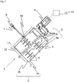
- zeigt eine Querschnittansicht eines Mischapparats gemäß einer ersten Ausführungsform der vorliegenden Erfindung.
- Fig. 2
- zeigt eine Schnittansicht A-A aus
Fig. 1 . - Fig. 3
- zeigt eine weitere Schnittansicht entlang der Linie B-B aus
Fig. 1 . - Fig. 4
- zeigt einen Mischapparat gemäß der ersten Ausführungsform der vorliegenden Erfindung, wobei hier allerdings ein Teil des Mantels weggelassen ist, so dass das Innere des Mischbehälters sichtbar ist, insbesondere das Mischwerkzeug.
- Fig. 5
- zeigt eine Ansicht von schräg unten auf den Mischbehälter der ersten Ausführungsform.
- Fig. 6
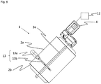
- zeigt eine isometrische Ansicht einer weiteren Ausführungsform des Mischapparats, welche ferner einen Wirbler aufweist.
- Fig. 7
- zeigt eine Querschnittansicht des Mischapparats der weiteren Ausführungsform wie in
Fig. 6 dargestellt, wobei hier zwei Wirbler vorgesehen sind.
- Fig. 1
- Fig. 13 is a cross-sectional view of a mixing apparatus according to a first embodiment of the present invention.
- Fig. 2
- shows a sectional view AA from
Fig. 1 . - Fig. 3
- FIG. 11 shows a further sectional view along the line BB from FIG
Fig. 1 . - Fig. 4
- shows a mixing apparatus according to the first embodiment of the present invention, but here a part of the jacket is omitted so that the interior of the mixing container is visible, in particular the mixing tool.
- Fig. 5
- shows a view obliquely from below of the mixing container of the first embodiment.
- Fig. 6
- Figure 12 shows an isometric view of another embodiment of the mixing apparatus which further includes a swirler.
- Fig. 7
- FIG. 13 shows a cross-sectional view of the mixing apparatus of the further embodiment as in FIG
Fig. 6 shown, with two vortices being provided here.
Aus
Ferner ist im Mantel 2a des Mischbehälters 2 eine Öffnung 6a (hier nicht gezeigt) vorgesehen, welche mit einem Verschlussmittel 6a versehen ist. Durch diese Öffnung kann eine Lanze 7 eingefahren werden, welche dazu angepasst ist, bis zur mittleren Welle 3a vorgeschoben werden zu können und mit dieser in Kontakt zu stehen. Am anderen Ende der Lanze 7, also außerhalb des Mischbehälters 2, ist ein Vibrationsmotor 8 an der Lanze angebracht, welcher Vibrationen auf die Lanze 7 und somit auch auf das Mischwerkzeug 3 übertragen kann, um dieses nach Gebrauch des Mischers leichter reinigen zu können. Ferner ist am unteren Ende der mittleren Welle 3a noch ein unterer Abstreifer 11 vorgesehen, welcher die Bodenplatte 2b von innen überstreicht, um diese im Bedarfsfall zu reinigen.Furthermore, an
Durch die Auswahl von speziellen Winkeln α, β und γ kann der Mischapparat einer besonderen Mischaufgabe angepasst werden, d.h. der Mischbehälter 2 kann um einen ganz bestimmten Winkel α um die Horizontale geneigt werden, die Mischvorrichtungen 3b können in einem bestimmten Winkel β voneinander angeordnet werden, und auch der Winkel γ, um welchen die Abstreifer 5 um die Richtung der mittleren Welle 3a verdreht sind, kann variieren.By selecting special angles α, β and γ, the mixing device can be adapted to a particular mixing task, ie the mixing
Die Winkel β zwischen zwei Mischvorrichtungen 3b kann beispielsweise vorzugsweise 10° bis 180°, weiter vorzugsweise 40° bis 90°, noch weiter vorzugsweise 45° bis 60° betragen.The angle β between two mixing
In
Ferner sind die beiden Antriebe 13a jeweils noch mit einem Wirbler-Frequenzumrichter 13d verbunden, damit diese Wirbler eben auch in beide Richtungen gefahren werden können und dieselben Vorteile aufweisen können wie auch der Antrieb 4 für gesamten Mischapparat (hier nicht gezeigt).Furthermore, the two
Es ist nicht unbedingt nötig, dass der Mischbehälter 2 eine zylindrische Form aufweist. Vielmehr können hier auch konus- oder kegelstumpfförmige Formen möglich sein. Auch die Anzahl der Mischvorrichtungen 3b, welche an einer inneren Welle 3a angebracht ist, kann je nach Mischaufgabe variieren.It is not absolutely necessary for the mixing
Ferner können an der inneren Welle 3a mehrere verschiedene Mischvorrichtungen 3b angebracht sein.Furthermore, a plurality of
Ferner können die Winkel γ an den Abstreifern 5 an den einzelnen Mischvorrichtungen 3b verschieden sein, müssen also nicht an jeder der einzelnen Mischvorrichtungen 3b gleich sein. Ferner können bei mehreren Mischvorrichtungen 3b verschiedene Arten von Verzweigungen 3c vorhanden sein. Diese können sich von den Mischvorrichtungen 3b in alle Raumrichtungen erstrecken.Furthermore, the angles γ on the
Im Folgenden soll ein Verfahren zum Mischen eines Mischguts in einem Mischapparat 1 gemäß der vorliegenden Erfindung beschrieben werden. Hier wird zuerst der Mischbehälter 2 mit den zu mischenden Komponenten beschickt. Dann erfolgt eine Rotation des Mischwerkzeugs 3 in eine Richtung. Nach einer gewissen Zeitspanne wird die Rotationsrichtung des Mischwerkzeugs 3 geändert. In einer Richtung wird das Material in die untere Wandung gedrückt und zusätzlich mit dem Abstreifer 5 zurück in Richtung der inneren Welle 3a gefördert, während in der anderen Betriebsrichtung hauptsächlich die Abstreifer 5 die Funktion erfüllen, die Innenseite des Behälters 2 zu reinigen. Die Abstreifer 5 erfüllen also zusätzlich zum Abstreifeffekt auch die Funktion einer Mischerschaufel.A method for mixing a material to be mixed in a
Nach Richtungsänderung wird das Mischgut somit in die Gegenrichtung gefördert. Je nach Mischgut wird die Drehrichtung des Mischwerkzeugs 3 pro Mischvorgang mehrfach geändert.After changing direction, the mix is conveyed in the opposite direction. Depending on the mix, the direction of rotation of the
Vorzugsweise wird während einer oder mehrerer der oben genannten Betriebsphasen noch ein Fluid, vorzugsweise Luft, durch die mindestens eine Düse 9 eingeblasenA fluid, preferably air, is preferably also blown in through the at least one
Nach Beendigung des Mischvorgangs wird die Rotation des Mischwerkzeugs gestoppt.When the mixing process is complete, the rotation of the mixing tool is stopped.
Zum Reinigen und zum Entleeren wird das Verfahren um die folgenden Schritte erweitert:
Die Auslauföffnung 10 wird geöffnet, damit das gemischte Material aus dem Mischbehälter 2 ausfließen kann. Durch die Bewegung in zwei verschiedene Richtungen kann der untere Abstreifer 11 den gesamten inneren Teil der Bodenplatte 2b vom Mischgut befreien und dieses durch die Auslauföffnung 12 aus dem Mischbehälter befördern, bis der Mischbehälter 2 leer ist. Optional kann dann die Lanze 7 in den Mischbehälter 2 eingefahren werden, bis ein Ende der Lanze 7 mit dem Mischwerkzeug 3, beispielsweise mit der mittleren Welle 3a, in Kontakt steht.For cleaning and draining, the procedure is expanded to include the following steps:
The
Dann wird der Vibrationsmotor eingeschaltet, damit das Mischwerkzeug 3 vom Mischgut befreit wird.The vibration motor is then switched on so that the
Nachdem alles Mischgut aus dem Mischbehälter 2 ausgelaufen ist, kann durch die mindestens eine Düse 9 Wasser in den Mischbehälter 2 eingebracht werden, um diesen weiter zu reinigen.After all the mixed material has run out of the mixing
In der vorliegenden Erfindung geht es um einen Mischapparat 1, welcher beispielsweise für die Mischung von Betonmaterialien eingesetzt wird. Hierbei ist der Mischbehälter 2 gegenüberüber der Horizontalen geneigt und der Antrieb 4, welcher das Mischwerkzeug 3 antreibt, ist in zwei entgegengesetzten Richtungen betreibbar. Dies dient zu einer Verbesserung der Mischeigenschaften sowie der Verkürzung der Mischzeit.The present invention concerns a
Claims (10)
- Mixing apparatus (1), comprising:a mixing container (2) comprising a shell (2a) and a bottom plate (2b),a mixing tool (3) which is rotatably provided in the mixing container (2),a drive (4) which drives the mixing tool (3),wherein the mixing container (2) is inclined with respect to the horizontal,and wherein the drive (4) which drives the mixing tool (3) is adapted to be operated in two opposite directions for mixing, wherein the mixing apparatus (1) is designed as a single-shaft mixer,wherein the mixing tool (3) comprises a shaft (3a) centrally arranged in the mixing container (2), as well as at least one mixing device (3b) attached thereto, which extends from the centrally arranged shaft (3a) towards the shell (2a) of the mixing container (2), wherein at the end of the mixing device (3b) facing away from the centrally arranged shaft (3a) a scraper (5) is arranged, which is adapted to abut with one side against the inside of the shell (2a) of the mixing container (2),wherein the scraper (5) is twisted by an angle (γ) of 10°-80° with respect to the direction of extension of the inner shaft (3a).
- Mixing apparatus (1) according to claim 1, wherein the angle of inclination of the mixing container (2) to the horizontal is adjustable in a range of 30° to 80°, preferably 15° to 70°, further preferably 30° to 60°.
- Mixing apparatus (1) according to any one of the preceding claims,
wherein the mixing device (3b) has branches (3c). - Mixing apparatus (1) according to claim 3,
wherein the scraper (5) is twisted with respect to the direction of extension of the inner shaft (3a) by an angle (γ) which is 15°-70°, further preferably 30° to 60°. - Mixing apparatus (1) according to claim 3 or 4, wherein a plurality of mixing devices (3b) are arranged on the centrally arranged shaft (3a) via fastening devices (3d), wherein the angle (β) enclosed by two of the plurality of mixing devices (3b) is variable in an adjustment mode but fixable in a mixing mode.
- Mixing apparatus (1) according to any one of the preceding claims, wherein an outlet opening (10) is provided on the bottom plate (2b) of the mixing container (2), wherein the outlet opening (10) is preferably closable by a closing means (10).
- mixing apparatus (1) according to any one of the preceding claims, further comprising a frequency converter (12) connected to and supplying power to the drive (4).
- Method of mixing a plurality of components with a mixing apparatus (1) according to any one of the preceding claims, comprising the steps of:- Filling the mixing container (2) with the components to be mixed,- Rotation of the mixing tool (3) in one direction,- Changing the direction of rotation of the mixing tool (3),- Stop the rotation of the mixing tool (3).
- Use of a mixing apparatus (1) according to any one of claims 1 - 7 for the production of concrete.
- Use of a mixing apparatus (1) according to any one of claims 1 - 7 for the production of cement emulsions, foamed concrete, colour mixtures and polystyrene concrete as well as high-quality concrete materials such as self-compacting concretes, ultra-high-strength concretes and mineral casting.
Applications Claiming Priority (1)
| Application Number | Priority Date | Filing Date | Title |
|---|---|---|---|
| DE102019201445.3A DE102019201445A1 (en) | 2019-02-05 | 2019-02-05 | Tilt mixer |
Publications (3)
| Publication Number | Publication Date |
|---|---|
| EP3702023A2 EP3702023A2 (en) | 2020-09-02 |
| EP3702023A3 EP3702023A3 (en) | 2020-11-18 |
| EP3702023B1 true EP3702023B1 (en) | 2021-09-01 |
Family
ID=69468440
Family Applications (1)
| Application Number | Title | Priority Date | Filing Date |
|---|---|---|---|
| EP20155397.1A Active EP3702023B1 (en) | 2019-02-05 | 2020-02-04 | Inclined mixer |
Country Status (3)
| Country | Link |
|---|---|
| EP (1) | EP3702023B1 (en) |
| DE (1) | DE102019201445A1 (en) |
| DK (1) | DK3702023T3 (en) |
Families Citing this family (9)
| Publication number | Priority date | Publication date | Assignee | Title |
|---|---|---|---|---|
| CN110618055A (en) * | 2019-09-24 | 2019-12-27 | 重庆国际复合材料股份有限公司 | Glass fiber chopped yarn bundling property detection method and system |
| CN112237861B (en) * | 2020-09-30 | 2023-01-03 | 西安汇诚化工科技有限公司 | Cutting fluid processing device |
| CN112428438A (en) * | 2020-11-18 | 2021-03-02 | 合肥东凯新型建材有限公司 | Proportioning and stirring device for high-strength concrete preparation |
| CN112917688A (en) * | 2021-01-21 | 2021-06-08 | 范晓彬 | Longitudinally placed concrete stirring device |
| DE202021106470U1 (en) | 2021-11-26 | 2022-01-10 | Kniele Gmbh | Improved Mixer Agitator |
| CN114953191A (en) * | 2022-05-10 | 2022-08-30 | 太原理工大学 | Ultrasonic wave generating device and concrete forming system |
| CN115301098A (en) * | 2022-08-05 | 2022-11-08 | 王文辉 | Preparation facilities of functional ceramic of mill's production |
| DE202022002144U1 (en) | 2022-09-29 | 2022-12-01 | Kniele Gmbh | compulsory mixer |
| CN116945368B (en) * | 2023-09-21 | 2023-12-05 | 山西路桥市政工程有限公司 | Cement stabilized macadam basic unit vibration mixing device |
Family Cites Families (18)
| Publication number | Priority date | Publication date | Assignee | Title |
|---|---|---|---|---|
| US1730713A (en) * | 1928-03-22 | 1929-10-08 | Alexander John | Plaster and mortar mixer |
| DE1182036B (en) * | 1963-02-26 | 1964-11-19 | Bauermeister Hermann Maschf | Machine for treating, in particular for dry conching and salving, of chocolate masses or the like. |
| US3197180A (en) * | 1963-10-11 | 1965-07-27 | Chemineer | Mixing device |
| DE2140759A1 (en) * | 1971-08-13 | 1973-02-22 | Brahim Ijac Kader | CONTINUOUS MIXER |
| US3738774A (en) * | 1971-12-16 | 1973-06-12 | K Lutz | Asphalt mixer tip and shank assembly |
| DE3241193A1 (en) * | 1982-11-08 | 1984-05-10 | Dietrich Dipl.-Ing. 6240 Königstein Maurer | Device for the continuous mixing of dry material with a liquid and for conveying the mixed material |
| DE3310570A1 (en) * | 1983-03-23 | 1984-09-27 | Hudelmaier, Ingrid, 7900 Ulm | CONCRETE MIXER |
| US4478515A (en) * | 1983-09-27 | 1984-10-23 | Stone Construction Equipment, Inc. | Mortar mixer with triple eight mixing action |
| DE8333124U1 (en) * | 1983-11-18 | 1988-04-28 | Alwin Berents Gmbh & Co Kg, 2805 Stuhr, De | |
| DE3604333A1 (en) * | 1986-02-12 | 1987-08-13 | Rudolf Ing Grad Riker | Single-shaft positive mixer |
| DE19512333A1 (en) * | 1995-04-01 | 1996-10-02 | Neuenkirchener Eisengieserei U | Dough mixing and kneading machine operating continuously under computer control |
| EP0836880A1 (en) * | 1996-10-16 | 1998-04-22 | Clariant GmbH | Mixer for the continuous processing of flowable materials |
| CH692274A5 (en) * | 1998-02-04 | 2002-04-30 | Gericke Ag | Continuous mixers, mixing plant with a continuous mixer and method of operation of such a plant. |
| KR101032289B1 (en) | 1998-05-18 | 2011-05-06 | 다케다 야쿠힌 고교 가부시키가이샤 | Fine granules |
| US6418948B1 (en) * | 1998-10-30 | 2002-07-16 | Thomas G. Harmon | Apparatus and method for removing concrete from interior surfaces of a concrete mixing drum |
| DE102004025318A1 (en) * | 2004-05-19 | 2005-12-08 | Rudolf Hartmann | Process and fermentation plant for the anaerobic fermentation of biogenic waste |
| DE102008033644A1 (en) * | 2008-07-17 | 2010-01-21 | Elba-Werk Maschinen-Gesellschaft Mbh | Concrete mixer i.e. planetary counter-flow mixer, has drive arrangement arranged such that angular speed of rotation movement of mixer and angular speed of circulating movement of mixer are adjusted independent of each other |
| CN106179023A (en) * | 2016-08-30 | 2016-12-07 | 伊泽瑞尔(大连)科技有限公司 | A kind of horizontal intelligent permanent magnet straight drive variable-frequency control agitating device |
-
2019
- 2019-02-05 DE DE102019201445.3A patent/DE102019201445A1/en active Pending
-
2020
- 2020-02-04 EP EP20155397.1A patent/EP3702023B1/en active Active
- 2020-02-04 DK DK20155397.1T patent/DK3702023T3/en active
Also Published As
| Publication number | Publication date |
|---|---|
| DE102019201445A1 (en) | 2020-08-06 |
| DK3702023T3 (en) | 2021-11-15 |
| EP3702023A2 (en) | 2020-09-02 |
| EP3702023A3 (en) | 2020-11-18 |
Similar Documents
| Publication | Publication Date | Title |
|---|---|---|
| EP3702023B1 (en) | Inclined mixer | |
| EP1121193B1 (en) | Compulsory mixer used, in particular, as a cement mixer | |
| EP3145687B1 (en) | Continuous mixer apparatus for producing a foamed slurry and method for operating such a continuous mixer apparatus | |
| DE3901894C5 (en) | Device for stirring a flowable medium | |
| EP2460581B1 (en) | Method for mixing powder or granular materials, and mixing machine | |
| EP2722103A2 (en) | Forced mixer with self-cleaning function and use of air inlets therefor | |
| DE10204921C1 (en) | Dispersing apparatus | |
| DE2637558A1 (en) | METHOD AND DEVICE FOR GENERATING A CONTINUOUS FLOW OF MATERIAL | |
| DE10006253A1 (en) | Stirrer | |
| EP2754351B1 (en) | Mixer with mixing blade with a vertical axis of rotation and mixing method | |
| DE102011006636A1 (en) | Pug mill mixer i.e. concrete mixer, for use in construction site for mixing liquid, powdery and/or granular components, has vibrating device coupled to shaft and actuated to simulate shaft for enabling vibration movements | |
| EP2011563A1 (en) | Mixing-drying unit and/or reactor | |
| DE4006846C2 (en) | ||
| DE10110910C1 (en) | Mixer, used in production of pasty products, e.g. creams, ointments and emulsions, comprises mixing container, and outer/inner stirrer in container that rotates about symmetrical axis of container using drive | |
| DE19507181A1 (en) | Dough mixer assembly with horizontal contra-rotating concentric mixer blades | |
| DE10260972B4 (en) | Device for circulating liquid manure and wastewater in a storage container | |
| DE102004036273B4 (en) | Closing and removal device for a silo or bulk container | |
| DE1558105A1 (en) | Device for processing refractory materials, in particular foundry molded materials | |
| EP0211230B1 (en) | Installation for mixing solid materials and liquids | |
| DE102008005018B3 (en) | Stirrer and agitator for mixing and / or homogenizing fluid media | |
| EP2119496B1 (en) | Mixing device and tool | |
| EP1256373B1 (en) | Propeller stirrer for agitating crude oil | |
| DE202022002144U1 (en) | compulsory mixer | |
| DE202021106470U1 (en) | Improved Mixer Agitator | |
| DE10105007C2 (en) | Mixing tool for a mixing device with planetary movement |
Legal Events
| Date | Code | Title | Description |
|---|---|---|---|
| PUAI | Public reference made under article 153(3) epc to a published international application that has entered the european phase |
Free format text: ORIGINAL CODE: 0009012 |
|
| STAA | Information on the status of an ep patent application or granted ep patent |
Free format text: STATUS: THE APPLICATION HAS BEEN PUBLISHED |
|
| AK | Designated contracting states |
Kind code of ref document: A2 Designated state(s): AL AT BE BG CH CY CZ DE DK EE ES FI FR GB GR HR HU IE IS IT LI LT LU LV MC MK MT NL NO PL PT RO RS SE SI SK SM TR |
|
| AX | Request for extension of the european patent |
Extension state: BA ME |
|
| PUAL | Search report despatched |
Free format text: ORIGINAL CODE: 0009013 |
|
| STAA | Information on the status of an ep patent application or granted ep patent |
Free format text: STATUS: REQUEST FOR EXAMINATION WAS MADE |
|
| AK | Designated contracting states |
Kind code of ref document: A3 Designated state(s): AL AT BE BG CH CY CZ DE DK EE ES FI FR GB GR HR HU IE IS IT LI LT LU LV MC MK MT NL NO PL PT RO RS SE SI SK SM TR |
|
| AX | Request for extension of the european patent |
Extension state: BA ME |
|
| RIC1 | Information provided on ipc code assigned before grant |
Ipc: B01F 7/02 20060101AFI20201015BHEP Ipc: B01F 13/02 20060101ALI20201015BHEP Ipc: B28C 5/12 20060101ALI20201015BHEP Ipc: B28C 5/48 20060101ALI20201015BHEP Ipc: B01F 7/00 20060101ALI20201015BHEP Ipc: B08B 7/02 20060101ALI20201015BHEP Ipc: B01F 15/00 20060101ALI20201015BHEP Ipc: B28C 7/12 20060101ALI20201015BHEP |
|
| 17P | Request for examination filed |
Effective date: 20201110 |
|
| RBV | Designated contracting states (corrected) |
Designated state(s): AL AT BE BG CH CY CZ DE DK EE ES FI FR GB GR HR HU IE IS IT LI LT LU LV MC MK MT NL NO PL PT RO RS SE SI SK SM TR |
|
| STAA | Information on the status of an ep patent application or granted ep patent |
Free format text: STATUS: EXAMINATION IS IN PROGRESS |
|
| 17Q | First examination report despatched |
Effective date: 20210201 |
|
| GRAP | Despatch of communication of intention to grant a patent |
Free format text: ORIGINAL CODE: EPIDOSNIGR1 |
|
| STAA | Information on the status of an ep patent application or granted ep patent |
Free format text: STATUS: GRANT OF PATENT IS INTENDED |
|
| INTG | Intention to grant announced |
Effective date: 20210608 |
|
| GRAS | Grant fee paid |
Free format text: ORIGINAL CODE: EPIDOSNIGR3 |
|
| GRAA | (expected) grant |
Free format text: ORIGINAL CODE: 0009210 |
|
| STAA | Information on the status of an ep patent application or granted ep patent |
Free format text: STATUS: THE PATENT HAS BEEN GRANTED |
|
| AK | Designated contracting states |
Kind code of ref document: B1 Designated state(s): AL AT BE BG CH CY CZ DE DK EE ES FI FR GB GR HR HU IE IS IT LI LT LU LV MC MK MT NL NO PL PT RO RS SE SI SK SM TR |
|
| REG | Reference to a national code |
Ref country code: GB Ref legal event code: FG4D Free format text: NOT ENGLISH |
|
| REG | Reference to a national code |
Ref country code: CH Ref legal event code: EP Ref country code: AT Ref legal event code: REF Ref document number: 1425614 Country of ref document: AT Kind code of ref document: T Effective date: 20210915 |
|
| REG | Reference to a national code |
Ref country code: DE Ref legal event code: R096 Ref document number: 502020000160 Country of ref document: DE |
|
| REG | Reference to a national code |
Ref country code: IE Ref legal event code: FG4D Free format text: LANGUAGE OF EP DOCUMENT: GERMAN |
|
| REG | Reference to a national code |
Ref country code: DK Ref legal event code: T3 Effective date: 20211110 |
|
| REG | Reference to a national code |
Ref country code: DE Ref legal event code: R079 Ref document number: 502020000160 Country of ref document: DE Free format text: PREVIOUS MAIN CLASS: B01F0007020000 Ipc: B01F0027600000 |
|
| REG | Reference to a national code |
Ref country code: SE Ref legal event code: TRGR |
|
| REG | Reference to a national code |
Ref country code: LT Ref legal event code: MG9D |
|
| REG | Reference to a national code |
Ref country code: NL Ref legal event code: MP Effective date: 20210901 |
|
| PG25 | Lapsed in a contracting state [announced via postgrant information from national office to epo] |
Ref country code: ES Free format text: LAPSE BECAUSE OF FAILURE TO SUBMIT A TRANSLATION OF THE DESCRIPTION OR TO PAY THE FEE WITHIN THE PRESCRIBED TIME-LIMIT Effective date: 20210901 Ref country code: RS Free format text: LAPSE BECAUSE OF FAILURE TO SUBMIT A TRANSLATION OF THE DESCRIPTION OR TO PAY THE FEE WITHIN THE PRESCRIBED TIME-LIMIT Effective date: 20210901 Ref country code: FI Free format text: LAPSE BECAUSE OF FAILURE TO SUBMIT A TRANSLATION OF THE DESCRIPTION OR TO PAY THE FEE WITHIN THE PRESCRIBED TIME-LIMIT Effective date: 20210901 Ref country code: HR Free format text: LAPSE BECAUSE OF FAILURE TO SUBMIT A TRANSLATION OF THE DESCRIPTION OR TO PAY THE FEE WITHIN THE PRESCRIBED TIME-LIMIT Effective date: 20210901 Ref country code: NO Free format text: LAPSE BECAUSE OF FAILURE TO SUBMIT A TRANSLATION OF THE DESCRIPTION OR TO PAY THE FEE WITHIN THE PRESCRIBED TIME-LIMIT Effective date: 20211201 Ref country code: LT Free format text: LAPSE BECAUSE OF FAILURE TO SUBMIT A TRANSLATION OF THE DESCRIPTION OR TO PAY THE FEE WITHIN THE PRESCRIBED TIME-LIMIT Effective date: 20210901 Ref country code: BG Free format text: LAPSE BECAUSE OF FAILURE TO SUBMIT A TRANSLATION OF THE DESCRIPTION OR TO PAY THE FEE WITHIN THE PRESCRIBED TIME-LIMIT Effective date: 20211201 |
|
| PG25 | Lapsed in a contracting state [announced via postgrant information from national office to epo] |
Ref country code: PL Free format text: LAPSE BECAUSE OF FAILURE TO SUBMIT A TRANSLATION OF THE DESCRIPTION OR TO PAY THE FEE WITHIN THE PRESCRIBED TIME-LIMIT Effective date: 20210901 Ref country code: LV Free format text: LAPSE BECAUSE OF FAILURE TO SUBMIT A TRANSLATION OF THE DESCRIPTION OR TO PAY THE FEE WITHIN THE PRESCRIBED TIME-LIMIT Effective date: 20210901 Ref country code: GR Free format text: LAPSE BECAUSE OF FAILURE TO SUBMIT A TRANSLATION OF THE DESCRIPTION OR TO PAY THE FEE WITHIN THE PRESCRIBED TIME-LIMIT Effective date: 20211202 |
|
| PGFP | Annual fee paid to national office [announced via postgrant information from national office to epo] |
Ref country code: DK Payment date: 20220216 Year of fee payment: 3 |
|
| PG25 | Lapsed in a contracting state [announced via postgrant information from national office to epo] |
Ref country code: IS Free format text: LAPSE BECAUSE OF FAILURE TO SUBMIT A TRANSLATION OF THE DESCRIPTION OR TO PAY THE FEE WITHIN THE PRESCRIBED TIME-LIMIT Effective date: 20220101 Ref country code: SM Free format text: LAPSE BECAUSE OF FAILURE TO SUBMIT A TRANSLATION OF THE DESCRIPTION OR TO PAY THE FEE WITHIN THE PRESCRIBED TIME-LIMIT Effective date: 20210901 Ref country code: SK Free format text: LAPSE BECAUSE OF FAILURE TO SUBMIT A TRANSLATION OF THE DESCRIPTION OR TO PAY THE FEE WITHIN THE PRESCRIBED TIME-LIMIT Effective date: 20210901 Ref country code: RO Free format text: LAPSE BECAUSE OF FAILURE TO SUBMIT A TRANSLATION OF THE DESCRIPTION OR TO PAY THE FEE WITHIN THE PRESCRIBED TIME-LIMIT Effective date: 20210901 Ref country code: PT Free format text: LAPSE BECAUSE OF FAILURE TO SUBMIT A TRANSLATION OF THE DESCRIPTION OR TO PAY THE FEE WITHIN THE PRESCRIBED TIME-LIMIT Effective date: 20220103 Ref country code: NL Free format text: LAPSE BECAUSE OF FAILURE TO SUBMIT A TRANSLATION OF THE DESCRIPTION OR TO PAY THE FEE WITHIN THE PRESCRIBED TIME-LIMIT Effective date: 20210901 Ref country code: EE Free format text: LAPSE BECAUSE OF FAILURE TO SUBMIT A TRANSLATION OF THE DESCRIPTION OR TO PAY THE FEE WITHIN THE PRESCRIBED TIME-LIMIT Effective date: 20210901 Ref country code: CZ Free format text: LAPSE BECAUSE OF FAILURE TO SUBMIT A TRANSLATION OF THE DESCRIPTION OR TO PAY THE FEE WITHIN THE PRESCRIBED TIME-LIMIT Effective date: 20210901 Ref country code: AL Free format text: LAPSE BECAUSE OF FAILURE TO SUBMIT A TRANSLATION OF THE DESCRIPTION OR TO PAY THE FEE WITHIN THE PRESCRIBED TIME-LIMIT Effective date: 20210901 |
|
| PGFP | Annual fee paid to national office [announced via postgrant information from national office to epo] |
Ref country code: SE Payment date: 20220222 Year of fee payment: 3 |
|
| REG | Reference to a national code |
Ref country code: DE Ref legal event code: R097 Ref document number: 502020000160 Country of ref document: DE |
|
| PLBE | No opposition filed within time limit |
Free format text: ORIGINAL CODE: 0009261 |
|
| STAA | Information on the status of an ep patent application or granted ep patent |
Free format text: STATUS: NO OPPOSITION FILED WITHIN TIME LIMIT |
|
| 26N | No opposition filed |
Effective date: 20220602 |
|
| PG25 | Lapsed in a contracting state [announced via postgrant information from national office to epo] |
Ref country code: SI Free format text: LAPSE BECAUSE OF FAILURE TO SUBMIT A TRANSLATION OF THE DESCRIPTION OR TO PAY THE FEE WITHIN THE PRESCRIBED TIME-LIMIT Effective date: 20210901 |
|
| PG25 | Lapsed in a contracting state [announced via postgrant information from national office to epo] |
Ref country code: MC Free format text: LAPSE BECAUSE OF FAILURE TO SUBMIT A TRANSLATION OF THE DESCRIPTION OR TO PAY THE FEE WITHIN THE PRESCRIBED TIME-LIMIT Effective date: 20210901 |
|
| REG | Reference to a national code |
Ref country code: BE Ref legal event code: MM Effective date: 20220228 |
|
| PG25 | Lapsed in a contracting state [announced via postgrant information from national office to epo] |
Ref country code: LU Free format text: LAPSE BECAUSE OF NON-PAYMENT OF DUE FEES Effective date: 20220204 |
|
| PG25 | Lapsed in a contracting state [announced via postgrant information from national office to epo] |
Ref country code: IE Free format text: LAPSE BECAUSE OF NON-PAYMENT OF DUE FEES Effective date: 20220204 |
|
| PG25 | Lapsed in a contracting state [announced via postgrant information from national office to epo] |
Ref country code: BE Free format text: LAPSE BECAUSE OF NON-PAYMENT OF DUE FEES Effective date: 20220228 |
|
| PGFP | Annual fee paid to national office [announced via postgrant information from national office to epo] |
Ref country code: FR Payment date: 20230227 Year of fee payment: 4 |
|
| PGFP | Annual fee paid to national office [announced via postgrant information from national office to epo] |
Ref country code: IT Payment date: 20230228 Year of fee payment: 4 Ref country code: DE Payment date: 20230227 Year of fee payment: 4 |
|
| P01 | Opt-out of the competence of the unified patent court (upc) registered |
Effective date: 20230523 |
|
| REG | Reference to a national code |
Ref country code: DK Ref legal event code: EBP Effective date: 20230228 |
|
| REG | Reference to a national code |
Ref country code: CH Ref legal event code: PL |
|
| REG | Reference to a national code |
Ref country code: SE Ref legal event code: EUG |
|
| PG25 | Lapsed in a contracting state [announced via postgrant information from national office to epo] |
Ref country code: SE Free format text: LAPSE BECAUSE OF NON-PAYMENT OF DUE FEES Effective date: 20230205 Ref country code: LI Free format text: LAPSE BECAUSE OF NON-PAYMENT OF DUE FEES Effective date: 20230228 Ref country code: CH Free format text: LAPSE BECAUSE OF NON-PAYMENT OF DUE FEES Effective date: 20230228 |
|
| PG25 | Lapsed in a contracting state [announced via postgrant information from national office to epo] |
Ref country code: DK Free format text: LAPSE BECAUSE OF NON-PAYMENT OF DUE FEES Effective date: 20230228 |