EP3701835A1 - Vorrichtung zur verbindung eines frontelements mit einem seitenteil eines bewegbaren möbelteils - Google Patents
Vorrichtung zur verbindung eines frontelements mit einem seitenteil eines bewegbaren möbelteils Download PDFInfo
- Publication number
- EP3701835A1 EP3701835A1 EP20158213.7A EP20158213A EP3701835A1 EP 3701835 A1 EP3701835 A1 EP 3701835A1 EP 20158213 A EP20158213 A EP 20158213A EP 3701835 A1 EP3701835 A1 EP 3701835A1
- Authority
- EP
- European Patent Office
- Prior art keywords
- catch hook
- basic position
- base body
- clamping surface
- front element
- Prior art date
- Legal status (The legal status is an assumption and is not a legal conclusion. Google has not performed a legal analysis and makes no representation as to the accuracy of the status listed.)
- Granted
Links
Images


Classifications
-
- A—HUMAN NECESSITIES
- A47—FURNITURE; DOMESTIC ARTICLES OR APPLIANCES; COFFEE MILLS; SPICE MILLS; SUCTION CLEANERS IN GENERAL
- A47B—TABLES; DESKS; OFFICE FURNITURE; CABINETS; DRAWERS; GENERAL DETAILS OF FURNITURE
- A47B88/00—Drawers for tables, cabinets or like furniture; Guides for drawers
- A47B88/90—Constructional details of drawers
- A47B88/944—Drawers characterised by the front panel
- A47B88/95—Drawers characterised by the front panel characterised by connection means for the front panel
-
- A—HUMAN NECESSITIES
- A47—FURNITURE; DOMESTIC ARTICLES OR APPLIANCES; COFFEE MILLS; SPICE MILLS; SUCTION CLEANERS IN GENERAL
- A47B—TABLES; DESKS; OFFICE FURNITURE; CABINETS; DRAWERS; GENERAL DETAILS OF FURNITURE
- A47B88/00—Drawers for tables, cabinets or like furniture; Guides for drawers
- A47B88/90—Constructional details of drawers
- A47B88/944—Drawers characterised by the front panel
- A47B88/95—Drawers characterised by the front panel characterised by connection means for the front panel
- A47B2088/955—Drawers characterised by the front panel characterised by connection means for the front panel fastening the front panel using a toggle-lever
Definitions
- the invention relates to a device for connecting a front element to a side part of a movable furniture part, in particular a drawer, with at least two fastening units lying one above the other in the height direction of the front element, one of which is an upper fastening unit and one that can be fastened to the inside of the front element and is fastened to the inside from the inside
- the catching device having a front and a rear side in the base body and having a catch hook which is pivotably mounted on the base body between a basic position and a tensioning position and is pretensioned by a spring device, the catch hook has a clamping surface facing the back of the base body, which engages behind the holding section of the holding projection in the clamping position and the front element on the side enteil tense.
- a device of the type mentioned is for example from WO 2012/069339 A1 known.
- the connecting fitting disclosed there has a frame adapter which can be fastened to a frame and on which a locking device is arranged.
- the locking device works with a support device together, which in turn is attached to the front panel.
- the locking device has a base bracket which is attached to the frame adapter and on which a locking lever is pivotably mounted.
- the locking lever is spring-loaded and cooperates with a release lever which is both pivotably mounted on the base bracket and is designed to be movable relative to the locking lever.
- a link in the form of a curved elongated hole is formed on the locking lever, in which a pin formed on the release lever is received in such a way that the locking lever is held in an open position against the spring force of the spring.
- a guide track on the base bracket is assigned to the pin on the release lever.
- a pin is provided on the support device, which strikes the release lever when it is retracted and pushes the pin of the release lever held in the link out of its holding position, whereby the spring force of the spring causes the locking lever to pivot in the direction of the closed position, the pin on the support device from Locking lever is engaged from behind.
- the object of the invention is to create a device for connecting a front element to a side part of a movable furniture part, which is constructed simply and inexpensively and, in particular, requires a smaller number of components compared to the prior art described above.
- the device according to the invention is characterized in that the catch hook is inclined with respect to the clamping surface and has an actuating surface adjoining this via an apex and facing the front side of the base body, which in the basic position lies in the insertion path of the holding projection, the catch hook being pretensioned into the basic position via the spring device, such that the holding section of the holding projection hits the actuating surface during the insertion process can and can press the catch hook against the force of the spring device from the basic position and the catch hook after the holding portion has passed the apex and has reached the area of the clamping surface, can pivot back through the force of the spring device in the direction of the basic position to the clamping surface on the Act holding section.
- the fastening of the front element in the sense of catching and tensioning the holding section of the holding projection can take place automatically when the holding projection is inserted.
- the holding section can push the catch hook away when it hits the actuating surface against the spring force of the spring device, the catch hook being able to snap back in the direction of the basic position after the apex is exceeded and from the apex the clamping surface is effective, which ensures the clamping of the front element to the side part.
- the actuating surface of the catch hook rises in its basic position from the front of the base body towards the rear up to the apex, the adjoining clamping surface in the basic position of the catch hook falling from the front of the base body towards the rear.
- the catch hook can be designed as a one-armed lever that moves between the basic position and the clamping position about a fixed pivot axis arranged on the base body is pivoted.
- the catch hook can be referred to as a catch pivot lever.
- pivot axis is arranged in the area between the actuating surface and the clamping surface.
- the pivot axis is arranged in the direction of the rear side of the base body behind the clamping surface.
- a relatively long lever arm is expediently formed between the pivot axis and the clamping surface.
- the spring device acts directly on the catch hook in order to bias the catch hook into the basic position. It is possible, for example, for the spring device to act on a longitudinal side of the catch hook which is arranged opposite a longitudinal side equipped with the actuating surface and the clamping surface.
- the spring device for biasing the catch hook into the basic position acts indirectly on the catch hook via a force introduction lever, the force introduction lever being articulated to the catch hook via a connecting joint.
- the catch hook forms a toggle lever together with the force introduction lever.
- the spring device has at least one compression spring or at least one tension spring.
- the direct coupling of the spring device and the catch hook is at least a compression spring connected on the one hand to the catch hook and on the other hand to the base body.
- At least one tension spring is connected on the one hand to the force introduction lever and on the other hand to the base head.
- the catch hook has a fork-shaped hook section which has two fork legs which are aligned parallel to one another and spaced apart from one another and which are oriented in the vertical direction in the basic position of the catch hook, such that an upwardly open receptacle for the retaining projection is formed between the fork legs is.
- the actuating surface and the adjoining clamping surface of the catch hook are formed by outer edges of the fork legs.
- the fork-shaped hook section of the catch hook thus has several functions, on the one hand it serves to form the upwardly open receptacle for receiving the holding projection, on the other hand it can also form the actuating surface and the adjoining clamping surface at the same time.
- the retaining projection assigned to the front element is designed as a retaining bolt, with a bolt shank and a bolt head that forms the retaining section and has a larger diameter than the bolt shank.
- the upper fastening unit is connected to the lower fastening interface via coupling means such that when the front element is released on the lower fastening unit via the coupling means at the same time the catch hook of the upper fastening unit can be pivoted out of the basic position to release the retaining projection.
- the coupling means have a connecting rod which is articulated on the one hand to a component of the lower fastening unit and on the other hand is articulated to the catch hook.
- the invention relates to a furniture part, in particular a drawer with a front element and two side parts, characterized by a device according to one of Claims 1 to 15.
- the invention comprises a piece of furniture with at least one furniture part, in particular a drawer, which has a front element with two side parts, characterized by a device according to one of Claims 1 to 16.
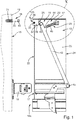
- the Figures 1 to 5 show a first exemplary embodiment of the device 11 according to the invention, which is used to attach a front element 12 to a side part 13.
- the front element 12 is designed as a front panel.
- the front panel and the side part 13 are part of a drawer or a drawer.
- the front element 12 is therefore to be attached to two opposite side parts 13, that is to say to a left and right side part 13. That in the Figures 1 to 5
- the illustrated first exemplary embodiment of the device 11 according to the invention can therefore also be present identically on the other second part in the example.
- the structure described below and the mode of operation of the device 11 therefore also apply in the same way to the other side part 13.
- the side part 13 can be designed as a drawer side wall which is attached to a running rail of a guide unit serving to guide the drawer.
- the side wall of the drawer can consist of wood, metal or plastic as a solid body.
- the side part 13 can also be designed as a drawer frame which accommodates components of the guide unit in the form of a hollow chamber frame.
- the device 11 according to the invention is described below by way of example with the use of a side part 13 designed as a hollow-chamber frame.
- the hollow-chamber frame can be designed as an extruded profile. Aluminum is suitable as an extrusion material. Alternatively, it is possible to manufacture the hollow chamber frame from sheet metal parts.
- the front element 12 that is to say the front panel in the example, can consist of wood, plastic or metal.
- the device 11 has at least two, in the example exactly two, fastening units 14a, 14b lying one above the other in the height direction of the front element 12 or side part 13.
- the lower fastening unit 14a is of less relevance in the following and is therefore only roughly described.
- the lower fastening unit 14a has a latching pawl 16 to be fastened on the inside 15 of the front element 12, which can retract into a latching receptacle 17 formed on the frame to fasten the front element 12 on the associated side part 13 in the form of the hollow-chamber frame and is latched there.
- the upper fastening unit 14b is of particular interest in the following.
- the upper fastening unit 14b has a holding projection 18 fastened to the inside 15 of the front element 12 and protruding from the inside 15 in the direction of the side part 13.
- the holding projection 18 has a holding section 19.
- the retaining projection 18 is designed as a retaining bolt, with a bolt shank 20 and a bolt head that forms the retaining section 19 and has a larger diameter than the bolt shank 20.
- the bolt shank 20 can have a threaded section for screwing into the front element 12.
- the threaded section of the retaining bolt is located on a dowel 21, in particular a wooden dowel, which in turn is to be introduced into a blind hole formed on the inside of the front element 12.
- a threadless section adjoins the threaded section in the axial direction of the bolt shank 20.
- the counterpart to the retaining projection 18 on the front element 12 is a catching device 22 fastened to the side part 13, that is to say to the frame.
- the catching device 22 has a base body 25 which has a front side 23 and a rear side 24 and on which a catch hook 26 is pivotably mounted between a basic position 27 and a clamping position 28.
- the catch hook 26 is biased into the basic position 27 by a spring device 29.
- the catch hook 26 has a clamping surface 30 facing the rear side 24 of the base body 25, which engages behind the holding section 19 of the holding projection 18 and clamps the front element 12 on the side part 13.
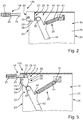
- the catch hook has an actuating surface 31 which is inclined with respect to the clamping surface 30 and adjoins it via an apex 31 and faces the front side 23 of the base body 25, which in the basic position 27 lies in the insertion path of the holding projection 18, the catch hook 26 via the spring device 29 in the basic position is pretensioned in such a way that the holding section 19 of the holding projection 18 can strike the actuating surface 31 during the insertion process and can push the catch hook 26 out of the basic position 27 against the force of the spring device 22 and the catch hook 26 after the holding section 19 passes the apex 31 and has reached the area of the clamping surface 30, by means of which the spring device 29 can pivot back in the direction of the basic position 27 in order to act with the clamping surface 30 on the holding section 19.
- the catch hook 26 has a fork-shaped hook section 33 which has two fork legs 34a, 34a, 34a, 34b, which in the basic position of the catch hook 26 are oriented in the height direction.
- the catch hook 26 is a relatively short, one-armed pivot lever which is mounted on the base body 25 such that it can pivot about a pivot axis 35.
- the pivot axis 35 is located essentially directly on the front side 23 of the base body 25, that is to say in the region of an insertion opening 36, which is open from the base body to the front side, for the holding projection 18.
- the base body is integrally connected to the rest of the hollow-chamber frame, that is, it is part of the hollow-chamber frame.
- the base body separately from the hollow-chamber frame and to place it on the hollow-chamber frame in the manner of a frame adapter and to fasten it there.
- the catch hook 26 is pivotably mounted with its pivot axis 35, on the one hand, on an outside of the base body and, on the other hand, on a bearing bracket 37 that is integrally connected to the rest of the base body and runs parallel to the outside.
- the bearing bracket 37 also forms the insertion opening 36 on its front face.
- the catch hook 26 is, as mentioned, designed as a short, one-armed pivot lever and is expediently also designed as a bent sheet metal component.
- the two fork legs 34a, 34b are connected to one another by a fork yoke 38.
- the two fork legs 34a, 34b run parallel to one another and are kept at a distance from one another by the fork yoke 38.
- the space between the two fork legs 34a, 34b forms the receptacle 39 for the threadless section of the holding projection 18.
- the distance between the two fork legs 34a, 34b to one another, i.e. the clear width of the receptacle 39, is smaller than the diameter of the retaining section 19, which is designed as a bolt head. This makes it possible for the bolt head to hit the catch hook 26 when it is inserted without it being caught in the Intake retracts.
- the fork legs 34a, 34b each have a characteristic contour and together form both the actuating surface 32 and the clamping surface 30 as well as the vertex 31 lying between the actuating surface and the clamping surface.
- the fork legs 34a, 34b each have the shape of a polygon.
- the actuating surface is formed by the front upper edges of the fork legs 34a, 34b, which in the in Figure 5 basic position shown extend obliquely upwards from the insertion opening 36 to the rear. In the direction from the front side 23 to the rear side 24 of the base body 25, the actuating surface is therefore inclined obliquely upward relative to the opening plane of the insertion opening 36.
- the actuation surface is a straight surface that begins in the area of the pivot axis 35 and ends at the vertex 31.
- the clamping surface 30 follows in the insertion direction after the apex 31, which in the example is designed as a curved surface is.
- the clamping surface 30 is formed by the rear upper edges of the fork legs 34a, 34b.
- pivot axis 35 is arranged in the area between the actuating surface 32 and the clamping surface 30.
- the catch hook is biased into the basic position 27 via the spring device 29.
- the spring device comprises at least one tension spring 40, which is mounted on the one hand on the base body 35 and on the other hand on the catching device 22.
- a window-like recess is formed on the base body 25, on which a suspension projection 41 is located for the end-side eyelet of the tension spring 40.
- the tension spring 40 does not act directly on the catch hook 26 but acts indirectly on the catch hook 26 via a force introduction lever 42.
- the force introduction lever 42 is articulated to the catch hook via a connecting joint 43. Overall, the catch hook together with the force introduction lever 42 forms a toggle lever.
- a suspension projection 44 for suspending the opposite suspension eye of the tension spring 40 is also formed on the force introduction lever 42.
- the upper fastening unit 14b is connected to the lower fastening unit 14a via coupling means, such that when the front element 12 is loosened on the lower fastening unit 14a via the Coupling means at the same time the catch hook 26 of the upper fastening unit 14b can be pivoted out of the basic position 27 to release the holding projection 18.
- the coupling means include the force introduction lever 42, which, as mentioned, is pivotably connected to the catch hook 26 via the connecting joint 43 and which, as in FIG Figure 1 shown, is connected via a further connecting hinge 45 to an adjusting mechanism of the lower fastening unit 14a.
- the holding projection 18 with the holding section 19 designed as a bolt head is guided in the direction of the insertion opening 36.
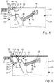
- the bolt head strikes the actuating surface 32, which in the basic position 27 runs obliquely from the insertion opening to the rear and upwards, whereby the catch hook is pivoted about the pivot axis 35 in a clockwise direction.
- the pivoting takes place against the spring force of the tension spring 40, which is tensioned when the catch hook 26 is pivoted.
- the catch hook 26 is pivoted approximately to the extent that the actuation surface 32 runs essentially parallel to the upper edge of the base body 26.
- the connecting joint 43 between the catch hook and the force introduction lever 42 is displaced downward and in the direction of the front of the base body 25, since the connecting joint 43 also swivels about the pivot axis 35.
- the spring force causes the tensioned tension spring pivoting the catch hook 26 counterclockwise, with the threadless section of the retaining projection 18 then moving into the receptacle 39 between the two fork legs 34a, 34b and the back of the bolt head sliding along the clamping surface 30. Since the clamping surface is curved in an arc shape, that is, has a convex shape, the front element 12 is drawn to the side part 13 when the bolt head slides further along, and the front element 12 is thus clamped to the side part 13.
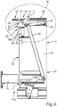
- the Figures 6 to 10 show a second exemplary embodiment of the device 11 according to the invention.
- the second exemplary embodiment differs from the previously described first exemplary embodiment in the different configuration of the catching device 22.
- the catch hook 26 is designed as a one-armed pivot lever, but not in such a short design as in the first exemplary embodiment, but as a relatively long pivot lever.
- the catch hook 26 thus has, in addition to the hook section 33 and the two fork legs 34a, 34b, also a relatively elongated base section 46 which, according to the exemplary embodiment, is designed as a rod.
- the base section 46 is mounted on the base body 25 at its rear end facing away from the hook section 33 so as to be pivotable about a pivot axis 35.
- the actuating surface 32 is designed in the same way as the first exemplary embodiment, i.e. is formed by the front upper edges of the two fork legs 34a, 34b, which in the basic position ( Figure 8 ) run diagonally upwards from the front of the main body to the rear.
- the clamping surface 30, which is also formed by the rear upper edges of the fork legs 34a, 34b, is not curved in an arc but has a straight course so that the fork legs 34a, 34b overall have the shape of a right triangle .
- a compression spring 47 is used here, which is supported on the one hand on the underside of the hook section 33 in the region of the fork yoke 38 and on the other hand on the base body 25.
- the catch hook 26 of the upper fastening unit 14b is connected to the lower fastening unit 14a via coupling means.
- a connecting lever 48 is present here, which on the one hand is pivotably articulated on the catch hook 26, in particular on its base section 46, and on the other hand is pivotably connected to an adjusting mechanism of the lower fastening unit 14a.
- the holding projection 18 with the holding section 19 designed as a bolt head is brought up to the catch hook 26 in advance.
- the bolt head hits the actuating surface 32 of the catch hook 26 and slides thereon, the catch hook pivoting counterclockwise around the pivot axis 35 against the spring force of the compression spring 47 downwards.
- the Figure 9 shows the situation exactly at the apex 31 of the catch hook 26. After the apex 31 has been exceeded, the catch hook 26 is pivoted back towards the basic position 27 by the spring force of the compression spring, whereby the threadless section of the retaining projection 18 enters the receptacle 39 between the two fork legs 34a, 34b.
- the circular pivoting movement of the hook about the pivot axis 35 generates a movement in the direction of the rear side of the base body when the back of the bolt head slides against one another on the clamping surface 30, whereby the front element 12 is clamped to the side part.
Landscapes
- Clamps And Clips (AREA)
Abstract
Description
- Die Erfindung betrifft eine Vorrichtung zur Verbindung eines Frontelementes mit einem Seitenteil eines bewegbaren Möbelteils, insbesondere Schublade, mit wenigstens zwei in Höhenrichtung des Frontelements übereinanderliegenden Befestigungseinheiten, von einen eine obere Befestigungseinheit einen an der Innenseite des Frontelements befestigbaren an dem befestigten Zustand von der Innenseite in Richtung Seitenteil wegragenden Haltevorsprung mit Halteabschnitt und eine am Seitenteil befestigbare Fangeinrichtung für den Haltevorsprung aufweist, wobei die Fangeinrichtung einen eine Vorderseite und eine Rückseite aufweisen im Grundkörper und einen am Grundkörper schwenkbar zwischen einer Grundstellung und einer Spannstellung gelagerten durch eine Federeinrichtung vorgespannten Fanghaken aufweist, wobei der Fanghaken eine der Rückseite des Grundkörpers zugewandte Spannfläche aufweist, die den Halteabschnitt des Haltevorsprungs in der Spannstellung hintergreift und das Frontelement an das Seitenteil spannt.
- Eine Vorrichtung der eingangs erwähnten Art ist beispielsweise aus der
WO 2012/069339 A1 bekannt. Der dort offenbarte Verbindungsbeschlag besitzt einen an einer Zarge befestigbaren Zargenadapter an dem eine Arretiereinrichtung angeordnet ist. Die Arretiereinrichtung wirkt mit einer Trageinrichtung zusammen, die ihrerseits an der Frontblende befestigt ist. Die Arretiereinrichtung weist einen Basiswinkel auf, der am Zargenadapter befestigt ist und an dem ein Arretierhebel schwenkbar gelagert ist. Der Arretierhebel ist federvorgespannt und wirkt mit einem Lösehebel zusammen, der sowohl schwenkbar am Basiswinkel gelagert ist als auch relativ beweglich zum Arretierhebel ausgebildet ist. Am Arretierhebel ist eine Kulisse in Form eines gekrümmten Langlochs ausgebildet, in das ein am Lösehebel ausgebildeter Stift derart aufgenommen ist, dass der Arretierhebel entgegen der Federkraft der Feder in einer Offenstellung gehalten ist. Dem Stift am Lösehebel ist eine Führungsbahn am Basiswinkel zugeordnet. An der Trageinrichtung ist ein Stift vorgesehen, der beim Einfahren auf den Lösehebel auftrifft und den in der Kulisse gehaltenen Stift des Lösehebels aus seiner Haltestellung drückt, wodurch die Federkraft der Feder ein Verschwenken des Arretierhebels in Richtung Schließstellung bewirkt, wobei der Stift an der Trageinrichtung vom Arretierhebel hintergriffen wird. - Aufgabe der Erfindung ist es, eine Vorrichtung zur Verbindung eines Frontelements mit einem Seitenteil eines bewegbaren Möbelteils zu schaffen, die einfach und kostengünstig aufgebaut ist und insbesondere gegenüber dem zuvor beschriebenen Stand der Technik mit einer geringeren Zahl an Bauteilen auskommt.
- Diese Aufgabe wird durch eine Vorrichtung zur Verbindung eines Frontelements mit einem Seitenteil eines bewegbaren Möbelteils mit den Merkmalen des unabhängigen Anspruchs 1 gelöst. Weiterbildungen der Erfindung sind in den Unteransprüchen dargestellt.
- Die erfindungsgemäße Vorrichtung zeichnet sich dadurch aus, dass der Fanghaken eine gegenüber der Spannfläche geneigte und daran über einen Scheitelpunkt anschließende, der Vorderseite des Grundkörpers zugewandte Betätigungsfläche aufweist, die in der Grundstellung im Einsteckweg des Haltevorsprungs liegt, wobei der Fanghaken über die Federeinrichtung in die Grundstellung vorgespannt ist, derart, dass der Halteabschnitt des Haltevorsprungs beim Einsteckvorgang auf die Betätigungsfläche auftreffen kann und den Fanghaken gegen die Kraft der Federeinrichtung aus der Grundstellung drücken kann und der Fanghaken nachdem der Halteabschnitt den Scheitelpunkt passiert hat und in den Bereich der Spannfläche gelangt ist, durch die Kraft der Federeinrichtung in Richtung Grundstellung zurückschwenken kann, um mit der Spannfläche auf den Halteabschnitt einzuwirken.
- Das Befestigen des Frontelements im Sinne des Fangens und Spannens des Halteabschnitts des Haltevorsprungs kann dabei selbsttätig beim Einstecken des Haltevorsprungs erfolgen. Der Halteabschnitt kann den Fanghaken beim Auftreffen auf die Betätigungsfläche gegen die Federkraft der Federeinrichtung wegdrücken, wobei der Fanghaken nach dem Überschreiten des Scheitelpunkts in Richtung Grundstellung zurückschnappen kann und ab dem Scheitelpunkt die Spannfläche wirksam ist, die für das Spannen des Frontelements an das Seitenteil sorgt.
- Bei einer Weiterbildung der Erfindung steigt die Betätigungsfläche des Fanghakens in dessen Grundstellung von der Vorderseite des Grundkörpers in Richtung Rückseite bis zum Scheitelpunkt an, wobei die sich daran anschließende Spannfläche in der Grundstellung des Fanghakens von der Vorderseite des Grundkörpers in Richtung Rückseite abfällt.
- Es ist möglich, dass der Fanghaken als einarmiger Hebel ausgebildet ist, der um eine am Grundkörper angeordnete ortsfeste Schwenkachse zwischen der Grundstellung und der Spannstellung schwenkbar gelagert ist. In diesem Fall kann der Fanghaken als Fang-Schwenkhebel bezeichnet werden.
- Es ist möglich, dass die Schwenkachse im Bereich zwischen der Betätigungsfläche und der Spannfläche angeordnet ist.
- Alternativ ist es denkbar, dass die Schwenkachse in Richtung Rückseite des Grundkörpers hinter der Spannfläche angeordnet ist. Zweckmäßigerweise ist in diesem Fall zwischen der Schwenkachse und der Spannfläche ein relativ langer Hebelarm ausgebildet.
- Bei einer Weiterbildung der Erfindung greift die Federeinrichtung zur Vorspannung des Fanghakens in die Grundstellung unmittelbaren am Fanghaken an. Es ist beispielsweise möglich, dass die Federeinrichtung an einer Längsseite des Fanghakens angreift, der einer mit der Betätigungsfläche und der Spannfläche ausgestatteten Längsseite entgegengesetzt angeordnet ist.
- Alternativ ist es denkbar, dass die Federeinrichtung zur Vorspannung des Fanghakens in die Grundstellung mittelbar über einen Krafteinleitungshebel am Fanghaken angreift, wobei der Krafteinleitungshebel über ein Verbindungsgelenk gelenkig mit dem Fanghaken verbunden ist. In diesem Fall bildet der Fanghaken gemeinsam mit dem Krafteinleitungshebel einen Kniehebel.
- Es ist möglich, dass die Federeinrichtung wenigstens eine Druckfeder oder wenigstens eine Zugfeder aufweist.
- Bei einer Weiterbildung der Erfindung ist bei der unmittelbaren Kopplung von Federeinrichtung und Fanghaken wenigstens eine Druckfeder einerseits mit dem Fanghaken und andererseits mit dem Grundkörper verbunden.
- Alternativ ist es denkbar, dass bei der mittelbaren Kopplung von Federeinrichtung und Fanghaken wenigstens eine Zugfeder einerseits mit dem Krafteinleitungshebel und andererseits mit dem Grundkopf verbunden ist.
- Bei einer Weiterbildung der Erfindung weist der Fanghaken einen gabelförmigen Hakenabschnitt auf, der zwei parallel zueinander ausgerichtete und zueinander beabstandete Gabelschenkel aufweist, die in der Grundstellung des Fanghakens in Höhenrichtung orientiert sind, derart, dass zwischen den Gabelschenkeln eine nach oben offene Aufnahme für die Haltevorsprung ausgebildet ist.
- In besonders bevorzugter Weise sind die Betätigungsfläche und die daran anschließende Spannfläche des Fanghakens durch Außenkanten der Gabelschenkel gebildet. Der gabelförmige Hakenabschnitt des Fanghakens weist also mehrere Funktionen auf, zum einen dient er zur Ausbildung der nach oben offenen Aufnahme zur Aufnahme des Haltevorsprungs, zum anderen kann er auch gleichzeitig die Betätigungs- und die daran anschließende Spannfläche bilden.
- Bei einer Weiterbildung der Erfindung ist der dem Frontelement zugeordnete Haltevorsprung als Haltebolzen ausgebildet, mit einem Bolzenschaft und einen den Halteabschnitt bildenden gegenüber dem Bolzenschaft einen größeren Durchmesser aufweisenden Bolzenkopf.
- Bei einer Weiterbildung der Erfindung ist die obere Befestigungseinheit mit der unteren Befestigungsschnittstelle über Kopplungsmittel verbunden, derart, dass beim Lösen des Frontelements an der unteren Befestigungseinheit über die Kopplungsmittel gleichzeitig der Fanghaken der oberen Befestigungseinheit aus der Grundstellung zur Freigabe des Haltevorsprungs herausschwenkbar ist.
- In besonders bevorzugter Weise weisen die Kopplungsmittel eine Verbindungsstange auf, die einerseits gelenkig mit einer Komponente der unteren Befestigungseinheit und andererseits gelenkig mit dem Fanghaken verbunden ist.
- Die Erfindung betrifft einen Möbelteil, insbesondere Schublade mit einem Frontelement und zwei Seitenteilen gekennzeichnet durch eine Vorrichtung nach einem der Ansprüche 1 bis 15.
- Schließlich umfasst die Erfindung ein Möbel, mit wenigstens einem Möbelteil, insbesondere Schublade, das ein Frontelement mit zwei Seitenteile aufweist, gekennzeichnet durch eine Vorrichtung nach einem der Ansprüche 1 bis 16.
- Bevorzugte Ausführungsbeispiele der Erfindung sind der Zeichnung dargestellt und werden im Folgenden näher erläutert. In der Zeichnung zeigen:
- Figur 1
- eine Seitenansicht auf einen Seitenteil des bewegbaren Möbelteils, dem ein erstes Ausführungsbeispiel der erfindungsgemäßen Vorrichtung zugeordnet ist,
- Figur 2
- eine vergrößerte Darstellung der Einzelheit X aus
Figur 1 , - Figur 3
- eine Darstellung gemäß
Figur 2 beim Herausschwenken des Fanghakens aus der Grundstellung, - Figur 4
- eine Darstellung gemäß den
Figuren 2 und 3 , nach dem der Haltevorsprung des Scheitelpunkt des Fanghakens passiert hat, - Figur 5
- eine Darstellung gemäß
Figur 4 mit der vom Fanghaken eingenommenen Spannstellung nach dem Spannen des Haltevorsprungs des zugeordneten Frontelements, - Figur 6
- eine Seitenansicht auf ein Seitenteil des bewegbaren Möbelteils, dem ein zweites Ausführungsbeispiel der erfindungsgemäßen Vorrichtung zugeordnet ist,
- Figur 7
- eine perspektivische Darstellung des Seitenteils mit der erfindungsgemäßen Vorrichtung zweitem Ausführungsbeispiel aus
Figur 6 , - Figur 8
- eine gesonderte Darstellung der Einzelheit Y aus
Figur 6 , wobei sich der Fanghaken in der Grundstellung befindet, - Figur 9
- die Einzeldarstellung von
Figur 8 , wobei der Haltevorsprung am Scheitelpunkt des Fanghakens angeordnet ist und der Fanghaken aus der Grundstellung herausgeschwenkt ist und - Figur 10
- eine Darstellung gemäß
Figur 9 , wobei der Haltevorsprung den Scheitelpunkt des Fanghakens passiert hat. - Die
Figuren 1 bis 5 zeigen ein erstes Ausführungsbeispiel der erfindungsgemäßen Vorrichtung 11, die zur Befestigung eines Frontelements 12 an einem Seitenteil 13 dient. - Das Frontelement 12 ist im Beispielsfall als Frontblende ausgebildet. Die Frontblende und das Seitenteil 13 sind Bestandteil einer Schublade bzw. eines Schubkastens. Daher ist das Frontelement 12 an zwei einander entgegengesetzten Seitenteilen 13, also an einem linken und rechten Seitenteil 13, zu befestigen. Das in den
Figuren 1 bis 5 dargestellte erste Ausführungsbeispiel der erfindungsgemäßen Vorrichtung 11 kann daher im Beispielsfall auch identisch am anderen zweiten Teil vorhanden sein. Der im Folgenden beschriebene Aufbau und die Funktionsweise der Vorrichtung 11 treffen daher in gleicher Weise auch auf das andere Seitenteil 13 zu. - Das Seitenteil 13 kann als Schubladen-Seitenwand ausgebildet sein, die an einer Laufschiene einer zur Führung der Schublade dienenden Führungseinheit befestigt ist. Die Schubladen-Seitenwand kann als Vollkörper aus Holz, Metall oder Kunststoff bestehen. Alternativ kann das Seitenteil 13 auch als Schubladen-Zarge ausgebildet sein, die in Form einer Hohlkammer-Zarge Komponenten der Führungseinheit aufnimmt. Die erfindungsgemäße Vorrichtung 11 wird im Folgenden beispielhaft beim Einsatz eines als Hohlkammer-Zarge ausgebildeten Seitenteils 13 beschrieben. Die Hohlkammer-Zarge kann als Strangpressprofil ausgeführt sein. Als Strangpressmaterial eignet sich Aluminium. Alternativ ist es möglich, die Hohlkammer-Zarge aus Metallblechteilen herzustellen.
- Das Frontelement 12, also im Beispielsfall die Frontblende, kann aus Holz, Kunststoff oder Metall bestehen.
- Wie insbesondere in
Figur 1 gezeigt, besitzt die Vorrichtung 11 wenigstens zwei, im Beispielsfall genau zwei, in Höhenrichtung des Frontelements 12 oder Seitenteils 13 übereinanderliegende Befestigungseinheiten 14a, 14b. Die untere Befestigungseinheit 14a ist im Folgenden von weniger Relevanz und wird daher nur grob beschrieben. Die untere Befestigungseinheit 14a besitzt eine an der Innenseite 15 des Frontelements 12 zu befestigende Rastklinke 16, die zur Befestigung des Frontelements 12 am zugeordneten Seitenteil 13 in Form der Hohlkammer-Zarge in eine an der Zarge ausgebildete Rastaufnahme 17 einfahren kann und dort verrastet wird. - Von besonderem Interesse ist im Folgenden die obere Befestigungseinheit 14b.
- Wie insbesondere in den
Figuren 1 bis 5 gezeigt, weist die obere Befestigungseinheit 14b einen an der Innenseite 15 des Frontelements 12 befestigtes und von der Innenseite 15 in Richtung Seitenteil 13 wegragenden Haltevorsprung 18 auf. Der Haltevorsprung 18 besitzt einen Halteabschnitt 19. - Im gezeigten Beispielsfall ist der Haltevorsprung 18 als Haltebolzen ausgebildet, mit einem Bolzenschaft 20 und einem den Halteabschnitt 19 bildenden gegenüber dem Bolzenschaft 20 einen größeren Durchmesser aufweisenden Bolzenkopf.
- Der Bolzenschaft 20 kann einen Gewindeabschnitt zum Einschrauben in das Frontelement 12 aufweisen. Im gezeigten Beispielsfall befindet sich der Gewindeabschnitt des Haltebolzens an einem Dübel 21, insbesondere Holzdübel, der seinerseits in ein an der Innenseite des Frontelementes 12 ausgebildetes Sackloch einzubringen ist.
- In Axialrichtung des Bolzenschafts 20 schließt sich an den Gewindeabschnitt ein gewindeloser Abschnitt an.
- Das Gegenstück zum Haltevorsprung 18 am Frontelement 12 ist eine am Seitenteil 13, also an der Zarge, befestigte Fangeinrichtung 22.
- Wie insbesondere in
Figur 1 gezeigt, weist die Fangeinrichtung 22 einen eine Vorderseite 23 und eine Rückseite 24 aufweisenden Grundkörper 25 auf, an dem ein Fanghaken 26 zwischen einer Grundstellung 27 und einer Spannstellung 28 schwenkbar gelagert ist. - Wie insbesondere in den
Figuren 1 bis 5 gezeigt, ist der Fanghaken 26 durch eine Federeinrichtung 29 in die Grundstellung 27 vorgespannt. Der Fanghaken 26 weist eine der Rückseite 24 des Grundkörpers 25 zugewandte Spannfläche 30 auf, die den Halteabschnitt 19 des Haltevorsprungs 18 hintergreift und das Frontelement 12 an das Seitenteil 13 spannt. - Wie insbesondere in den
Figuren 3 bis 5 gezeigt, besitzt der Fanghaken eine gegenüber der Spannfläche 30 geneigte und daran über einen Scheitelpunkt 31 anschließende, der Vorderseite 23 des Grundkörpers 25 zugewandte Betätigungsfläche 31, die in der Grundstellung 27 im Einsteckweg des Haltevorsprungs 18 liegt, wobei der Fanghaken 26 über die Federeinrichtung 29 in die Grundstellung vorgespannt ist, derart, dass der Halteabschnitt 19 des Haltevorsprungs 18 beim Einsteckvorgang auf die Betätigungsfläche 31 auftreffen kann und den Fanghaken 26 gegen die Kraft der Federeinrichtung 22 aus der Grundstellung 27 drücken kann und der Fanghaken 26 nachdem der Halteabschnitt 19 den Scheitelpunkt 31 passiert hat und in den Bereich der Spannfläche 30 gelangt ist, durch die Kraft der Federeinrichtung 29 in Richtung Grundstellung 27 zurückschwenken kann, um mit der Spannfläche 30 auf den Halteabschnitt 19 einzuwirken. - Wie beispielhaft anhand der
Figuren 1 bis 5 gemäß erstem Ausführungsbeispiel gezeigt, besitzt der Fanghaken 26 einen gabelförmigen Hakenabschnitt 33, der zwei parallel zueinander ausgerichtete und zueinander beabstandete Gabelschenkel 34a, 34b aufweist, die in der Grundstellung des Fanghakens 26 in Höhenrichtung orientiert sind. - Gemäß erstem Ausführungsbeispiel ist der Fanghaken 26 ein relativ kurzer, einarmiger Schwenkhebel, der um eine Schwenkachse 35 schwenkbar am Grundkörper 25 gelagert ist. Die Schwenkachse 35 befindet sich dabei im Wesentlichen unmittelbar an der Vorderseite 23 des Grundkörpers 25 also im Bereich einer vom Grundkörper zur Vorderseite hin offene Einstecköffnung 36 für den Haltevorsprung 18.
- Wie insbesondere in den
Figuren 1 bis 5 gezeigt, ist der Grundkörper einstückig mit dem Rest der Hohlkammer-Zarge verbunden, ist also Bestandteil der Hohlkammer-Zarge. Alternativ wäre es jedoch auch denkbar, den Grundkörper separat von der Hohlkammer-Zarge auszubilden und nach Art eines Zargen-Adapters auf die Hohlkammer-Zarge aufzusetzen und dort zu befestigen. - Wie insbesondere in
Figur 2 gezeigt, ist der Fanghaken 26 mit seiner Schwenkachse 35 einerseits an einer Außenseite des Grundkörpers und andererseits an einer einstückig mit dem Rest des Grundkörpers verbundenen parallel zur Außenseite verlaufenden Lagerlasche 37 schwenkbar gelagert. Die Lagerlasche 37 bildet zudem auch an ihrer vorderen Stirnseite die Einstecköffnung 36 aus. - Der Fanghaken 26 ist, wie erwähnt, als kurzer, einarmiger Schwenkhebel ausgebildet und zweckmäßiger Weise ebenfalls als Blechbiege-Bauteil ausgebildet. Dabei sind die beiden Gabelschenkel 34a, 34b durch ein Gabeljoch 38 miteinander verbunden. Die beiden Gabelschenkeln 34a, 34b verlaufen parallel zueinander und werden durch das Gabeljoch 38 auf Abstand zueinander gehalten. Der Zwischenraum zwischen den beiden Gabelschenkeln 34a, 34b bildet die Aufnahme 39 für den gewindelosen Abschnitt des Haltevorsprungs 18.
- Der Abstand der beiden Gabelschenkel 34a, 34b zueinander, also die lichte Weite der Aufnahme 39 ist kleiner als der Durchmesser des als Bolzenkopf ausgebildeten Halteabschnitts 19. Dadurch ist es möglich, dass der Bolzenkopf beim Einstecken auf den Fanghaken 26 auftreffen kann ohne dass er in die Aufnahme einfährt.
- Die Gabelschenkel 34a, 34b besitzen jeweils eine charakteristische Kontur und bilden gemeinsam sowohl die Betätigungsfläche 32 als auch die Spannfläche 30 sowie den zwischen der Betätigungsfläche und der Spannfläche liegenden Scheitelpunkt 31. Die Gabelschenkel 34a, 34b haben jeweils die Form eines Polygons.
- Wie insbesondere die Zusammenschau der
Figuren 2 bis 5 zeigt, wird die Betätigungsfläche von den vorderen Oberkanten der Gabelschenkel 34a, 34b gebildet, die in der inFigur 5 gezeigten Grundstellung von der Einstecköffnung 36 nach hinten nach schräg oben verlaufen. In Richtung von der Vorderseite 23 zur Rückseite 24 des Grundkörpers 25 ist die Betätigungsfläche also gegenüber der Mündungsebene der Einstecköffnung 36 schräg nach oben geneigt. - Im Beispielsfall ist die Betätigungsfläche eine gerade Fläche, die im Bereich der Schwenkachse 35 beginnt und am Scheitelpunkt 31 endet.
- Wie insbesondere in den
Figuren 2 bis 5 gezeigt, schließt sich in Einsteckrichtung nach dem Scheitelpunkt 31 die Spannfläche 30 an, die im Beispielsfall als Bogenfläche ausgebildet ist. Die Spannfläche 30 wird von den hinteren Oberkanten der Gabelschenkel 34a, 34b gebildet. - Charakteristisch für das erste Ausführungsbeispiel ist, dass die Schwenkachse 35 im Bereich zwischen der Betätigungsfläche 32 und der Spannfläche 30 angeordnet ist.
- Wie bereits erwähnt wird der Fanghaken über die Federeinrichtung 29 in die Grundstellung 27 vorgespannt. Im gezeigten Beispielsfall umfasst die Federeinrichtung wenigstens eine Zugfeder 40, die einerseits am Grundkörper 35 und andererseits an der Fangeinrichtung 22 gelagert ist.
- Wie beispielhaft in den
Figuren 2 bis 5 gezeigt, ist hierzu am Grundkörper 25 eine fensterartige Ausnehmung ausgebildet, an der sich ein Einhängevorsprung 41 für die endseitige Öse der Zugfeder 40 befindet. - Charakteristisch für das erste Ausführungsbeispiel ist, dass die Zugfeder 40 nicht direkt am Fanghaken 26 angreift sondern mittelbar über einen Krafteinleitungshebel 42 am Fanghaken 26 angreift. Der Krafteinleitungshebel 42 ist über ein Verbindungsgelenk 43 gelenkig mit dem Fanghaken verbunden. Insgesamt bildet der Fanghaken gemeinsam mit dem Krafteinleitungshebel 42 einen Kniehebel.
- Am Krafteinleitungshebel 42 ist ebenfalls ein Einhängevorsprung 44 zum Einhängen der entgegengesetzten Einhängeöse der Zugfeder 40 ausgebildet.
- Wie insbesondere in
Figur 1 gezeigt, ist die obere Befestigungseinheit 14b mit der unteren Befestigungseinheit 14a über Kopplungsmittel verbunden, derart, dass beim Lösen des Frontelements 12 an der unteren Befestigungseinheit 14a über die Kopplungsmittel gleichzeitig der Fanghaken 26 der oberen Befestigungseinheit 14b aus der Grundstellung 27 zur Freigabe des Haltevorsprungs 18 herausschwenkbar ist. - Zu den Kopplungsmitteln zählt der Krafteinleitungshebel 42, der, wie erwähnt, über das Verbindungsgelenk 43 mit dem Fanghaken 26 schwenkbar verbunden ist und der, wie in
Figur 1 gezeigt, über ein weiteres Verbindungsgelenk 45 mit einem Stellmechanismus der unteren Befestigungseinheit 14a verbunden ist. - Zum Verbinden des Frontelements 12 mit dem Seitenteil im Bereich der oberen Befestigungseinheit 14b wird, wie die Zusammenschau der
Figuren 2 bis 5 zeigt, zunächst der Haltevorsprung 18 mit dem als Bolzenkopf ausgebildeten Halteabschnitt 19 voraus in Richtung Einstecköffnung 36 geführt. Dabei trifft der Bolzenkopf auf die in der Grundstellung 27 schräg von der Einstecköffnung nach hinten oben verlaufende Betätigungsfläche 32, wodurch der Fanghaken in Uhrzeiger-Richtung um die Schwenkachse 35 verschwenkt wird. Das Verschwenken erfolgt gegen die Federkraft der Zugfeder 40, die beim Verschwenken des Fanghakens 26 gespannt wird. - Wie insbesondere die Zusammenschau der
Figuren 2 und 3 zeigt, wird der Fanghaken 26 in etwa soweit verschwenkt, dass die Betätigungsfläche 32 in wesentlichen parallel zur Oberkante des Grundkörpers 26 verläuft. Das Verbindungsgelenk 43 zwischen Fanghaken und Krafteinleitungshebel 42 wird nach unten und in Richtung Vorderseite des Grundkörpers 25 verlagert, da das Verbindungsgelenk 43 ebenfalls um die Schwenkachse 35 schwenkt. - Hat der Bolzenkopf den Scheitelpunkt 31 des Fanghakens 26 überschritten, so bewirkt die Federkraft der gespannten Zugfeder ein Zurückschwenken des Fanghakens 26 in GegenUhrzeigerrichtung, wobei dann der gewindelose Abschnitt des Haltevorsprungs 18 in die Aufnahme 39 zwischen den beiden Gabelschenkeln 34a, 34b einfährt und der Bolzenkopf mit seiner Rückseite an der Spannfläche 30 entlang gleitet. Da die Spannfläche bogenförmig gekrümmt ausgebildet ist, also einen konvexen Verlauf aufweist, wird beim weiteren Entlanggleiten des Bolzenkopfes das Frontelement 12 an das Seitenteil 13 gezogen und somit das Frontelement 12 an das Seitenteil 13 gespannt.
- Die
Figuren 6 bis 10 zeigen ein zweites Ausführungsbeispiel der erfindungsgemäßen Vorrichtung 11. Das zweite Ausführungsbeispiel unterscheidet sich von dem zuvor beschriebenen ersten Ausführungsbeispiel durch die andersartige Ausgestaltung der Fangeinrichtung 22. - Auch hier ist der Fanghaken 26 als einarmiger Schwenkhebel ausgebildet, jedoch nicht in derart kurzer Ausführung wie beim ersten Ausführungsbeispiel, sondern als relativ langer Schwenkhebel.
- Der Fanghaken 26 besitzt somit neben dem Hakenabschnitt 33 und den beiden Gabelschenkeln 34a, 34b noch einen relativ lang gestreckten Basisabschnitt 46, der gemäß Ausführungsbeispiel als Stange ausgebildet ist. Der Basisabschnitt 46 ist an seinem dem Hakenabschnitt 33 abgewandten hinteren Ende um eine Schwenkachse 35 schwenkbar am Grundkörper 25 gelagert.
- Die Betätigungsfläche 32 ist in gleicher Weise zum ersten Ausführungsbeispiel ausgebildet, wird also von den vorderen Oberkanten der beiden Gabelschenkel 34a, 34b gebildet, die in der Grundstellung (
Figur 8 ) von der Vorderseite des Grundkörpers nach hinten nach schräg oben verlaufen. - Im Gegensatz zum zuvor beschriebenen ersten Ausführungsbeispiel ist die Spannfläche 30, die ebenfalls von den hinteren Oberkanten der Gabelschenkel 34a, 34b gebildet wird, jedoch nicht bogenförmig gekrümmt sondern hat einen geraden Verlauf, so dass die Gabelschenkel 34a, 34b insgesamt die Form eines rechtwinkligen Dreiecks haben.
- Ein weiterer Unterschied zum zuvor beschriebenen ersten Ausführungsbeispiel ist die Ausgestaltung der Federeinrichtung 29. Im Gegensatz zum ersten Ausführungsbeispiel ist hier eine Druckfeder 47 eingesetzt, die einerseits an der Unterseite des Hakenabschnitts 33 im Bereich des Gabeljochs 38 und andererseits am Grundkörper 25 gelagert ist. Wie insbesondere die
Figuren 6 und7 zeigen, ist der Fanghaken 26 der oberen Befestigungseinheit 14b über Kopplungsmittel mit der unteren Befestigungseinheit 14a verbunden. Wie insbesondere inFigur 6 oder7 gezeigt, ist hier ein Verbindungshebel 48 vorhanden, der einerseits schwenkbar am Fanghaken 26, insbesondere an dessen Basisabschnitt 46 angelenkt ist und andererseits mit einem Stellmechanismus der unteren Befestigungseinheit 14a schwenkbar verbunden ist. - Zur Befestigung des Frontelements 12 am Seitenteil 13 im Bereich der oberen Befestigungseinheit 14b wird der Haltevorsprung 18 mit dem als Bolzenkopf ausgebildeten Halteabschnitt 19 voraus an den Fanghaken 26 herangeführt. Der Bolzenkopf trifft auf die Betätigungsfläche 32 des Fanghakens 26 und gleitet daran ab, wobei der Fanghaken in GegenUhrzeigerrichtung um die Schwenkachse 35 gegen die Federkraft der Druckfeder 47 nach unten schwenkt. Die
Figur 9 zeigt die Situation genau am Scheitelpunkt 31 des Fanghakens 26. Nach Überschreiten des Scheitelpunkts 31 wird der Fanghaken 26 durch die Federkraft der Druckfeder wieder zurück in Richtung Grundstellung 27 verschwenkt, wodurch der gewindelose Abschnitt des Haltevorsprungs 18 in die Aufnahme 39 zwischen den beiden Gabelschenkeln 34a, 34b gelangt. Durch die kreisförmige Schwenkbewegung des Fanghakens um die Schwenkachse 35 wird beim Aneinanderabgleiten der Rückseite des Bolzenkopfes an der Spannfläche 30 eine Bewegung in Richtung Rückseite des Grundkörpers erzeugt, wodurch das Frontelement 12 an das Seitenteil gespannt wird.
Claims (15)
- Vorrichtung zur Verbindung eines Frontelements (12) mit einem Seitenteil (13) eines bewegbaren Möbelteils, insbesondere Schublade, mit wenigstens zwei in Höhenrichtung des Frontelements (12) übereinander liegenden Befestigungseinheiten (14a, 14b), von denen eine obere Befestigungseinheit (14b) einen an der Innenseite (15) des Frontelements (12) befestigbaren und im befestigten Zustand von der Innenseite (15) in Richtung Seitenteil (13) weg ragenden Haltevorsprung (18) mit Halteabschnitt (19) und eine am Seitenteil (13) befestigbare Fangeinrichtung (22) für den Haltevorsprung (18) aufweist, wobei die Fangeinrichtung (22) einen eine Vorderseite (23) und eine Rückseite (24) aufweisenden Grundkörper (25) und einen am Grundkörper (25) schwenkbar zwischen einer Grundstellung (27) und einer Spannstellung (28) gelagerten durch eine Federeinrichtung (29) vorgespannten Fanghaken (26) aufweist, wobei der Fanghaken (26) eine der Rückseite (24) des Grundkörpers (25) zugewandte Spannfläche (30) aufweist, die den Halteabschnitt (19) des Haltevorsprungs (18) in der Spannstellung (30) hintergreift und das Frontelement (12) an das Seitenteil (13) spannt, dadurch gekennzeichnet, dass der Fanghaken (26) eine gegenüber der Spannfläche (30) geneigte und daran über einen Scheitelpunkt (31) anschließende, der Vorderseite (23) des Grundkörpers (25) zugewandte Betätigungsfläche (32) aufweist, die in der Grundstellung (27) im Einsteckweg des Haltevorsprung (18) liegt, wobei der Fanghaken (26) über die Federeinrichtung (29) in die Grundstellung (27) vorgespannt ist, derart, dass der Halteabschnitt (19) des Haltevorsprungs (18) beim Einsteckvorgang auf die Betätigungsfläche (32) auftreffen kann und den Fanghaken (26) gegen die Kraft der Federeinrichtung (29) aus der Grundstellung (27) drücken kann und der Fanghaken (26) nachdem der Halteabschnitt (19) den Scheitelpunkt (31) passiert hat und in den Bereich der Spannfläche (30) gelangt ist, durch die Kraft der Federeinrichtung (29) in Richtung Grundstellung (27) zurückschwenken kann, um mit der Spannfläche (30) auf den Halteabschnitt (19) einzuwirken.
- Vorrichtung nach Anspruch 1, dadurch gekennzeichnet, dass die Betätigungsfläche (32) des Fanghakens (26) in dessen Grundstellung (27) von der Vorderseite (23) des Grundkörpers (25) in Richtung Rückseite (24) bis zum Scheitelpunkt (31) ansteigt und die sich daran anschließende Spannfläche (30) in der Grundstellung (27) des Fanghakens (26) von der Vorderseite (23) des Grundkörpers (25) in Richtung Rückseite (24) abfällt.
- Vorrichtung nach Anspruch 1 oder 2, dadurch gekennzeichnet, dass der Fanghaken (26) als einarmiger Hebel ausgebildet ist, der um eine am Grundkörper (25) angeordnete ortsfeste Schwenkachse (35) zwischen der Grundstellung (27) und der Spannstellung schwenkbar gelagert ist, wobei vorzugsweise die Schwenkachse (35) im Bereich zwischen der Betätigungsfläche (32) und der Spannfläche (30) angeordnet ist.
- Vorrichtung nach Anspruch 3, dadurch gekennzeichnet, dass die Schwenkachse (35) in Richtung Rückseite (24) des Grundkörpers (25) hinter der Spannfläche (30) angeordnet ist, wobei vorzugsweise zwischen der Schwenkachse (35) und der Spannfläche (30) ein relativ langer Hebelarm ausgebildet ist.
- Vorrichtung nach Anspruch 3, dadurch gekennzeichnet, dass die Federeinrichtung (29) zur Vorspannung des Fanghakens (26) in die Grundstellung (27) unmittelbar am Fanghaken (26) angreift, insbesondere an einer Längsseite des Fanghakens (26), der einer mit der Betätigungsfläche (32) und der Spannfläche (30) ausgestatteten Längsseite entgegengesetzt angeordnet ist.
- Vorrichtung nach Anspruch 3 oder 4, dadurch gekennzeichnet, dass die Federeinrichtung (29) zur Vorspannung des Fanghakens (26) in die Grundstellung (27) mittelbar über einen Krafteinleitungshebel (42) am Fanghaken (26) angreift, wobei der Krafteinleitungshebel (42) über ein Verbindungsgelenk (43) gelenkig mit dem Fanghaken (26) verbunden ist.
- Vorrichtung nach einem der vorhergehenden Ansprüche, dadurch gekennzeichnet, dass die Federeinrichtung (29) wenigstens eine Druckfeder (47) oder wenigstens eine Zugfeder (40) aufweist, wobei vorzugsweise bei der unmittelbaren Kopplung von Federeinrichtung (29) und Fanghaken (26) wenigstens eine Druckfeder (47) einerseits mit dem Fanghaken (26) und andererseits mit dem Grundkörper (25) verbunden ist.
- Vorrichtung nach Anspruch 7, dadurch gekennzeichnet, dass bei der mittelbaren Kopplung von Federeinrichtung (29) und Fanghaken (26) wenigstens eine Zugfeder (40) einerseits mit dem Krafteinleitungshebel (42) und andererseits mit dem Grundkörper (25) verbunden ist.
- Vorrichtung nach einem der vorhergehenden Ansprüche, dadurch gekennzeichnet, dass der Fanghaken (26) einen gabelförmigen Hakenabschnitt (33) aufweist, der zwei parallel zueinander ausgerichtete und zueinander beabstandete Gabelschenkel (34a, 34b) aufweist, die in der Grundstellung (27) des Fanghakens (26) in Höhenrichtung orientiert sind, derart, dass zwischen den Gabelschenkeln (34a, 34b) eine nach oben offene Aufnahme (39) für den Haltevorsprung (18) ausgebildet ist.
- Vorrichtung nach Anspruch 9, dadurch gekennzeichnet, dass die Betätigungsfläche (32) und die daran anschließende Spannfläche (30) des Fanghakens (26) durch Außenkanten der Gabelschenkel (34a, 34b) gebildet sind.
- Vorrichtung nach einem der vorhergehenden Ansprüche, dadurch gekennzeichnet, dass der dem Frontelement (12) zugeordnete Haltevorsprung (18) als Haltebolzen ausgebildet ist, mit einem Bolzenschaft und einem den Haltabschnitt (19) bildenden gegenüber dem Bolzenschaft einen größeren Durchmesser aufweisenden Bolzenkopf.
- Vorrichtung nach einem der vorhergehenden Ansprüche, dadurch gekennzeichnet, dass die obere Befestigungseinheit (14b) mit der unteren Befestigungseinheit (14a) über Kopplungsmittel verbunden ist, derart, dass beim Lösen des Frontelements (12) an der unteren Befestigungseinheit (14a) über die Kopplungsmittel gleichzeitig der Fanghaken (26) der oberen Befestigungseinheit (14b) aus der Spannstellung zur Freigabe des Haltevorsprungs herausschwenkbar ist.
- Vorrichtung nach Anspruch 12, dadurch gekennzeichnet, dass die Kopplungsmittel eine Verbindungsstange (48) aufweisen, die einerseits gelenkig mit einer Komponente der unterer Befestigungseinheit (14a) und andererseits gelenkig mit dem Fanghaken (26) verbunden ist.
- Möbelteil, insbesondere Schublade, mit einem Frontelement (12) und zwei Seitenteilen (13), gekennzeichnet durch eine Vorrichtung (11) nach einem der Ansprüche 1 bis 13.
- Möbel, mit wenigstens einem Möbelteil, insbesondere Schublade, das ein Frontelement (12) und zwei Seitenteile (13) aufweist, gekennzeichnet durch eine Vorrichtung nach einem der Ansprüche 1 bis 14.
Applications Claiming Priority (1)
| Application Number | Priority Date | Filing Date | Title |
|---|---|---|---|
| DE202019101142.4U DE202019101142U1 (de) | 2019-02-28 | 2019-02-28 | Vorrichtung zur Verbindung eines Frontelements mit einem Seitenteil eines bewegbaren Möbelteils |
Publications (2)
| Publication Number | Publication Date |
|---|---|
| EP3701835A1 true EP3701835A1 (de) | 2020-09-02 |
| EP3701835B1 EP3701835B1 (de) | 2022-08-31 |
Family
ID=69784035
Family Applications (1)
| Application Number | Title | Priority Date | Filing Date |
|---|---|---|---|
| EP20158213.7A Active EP3701835B1 (de) | 2019-02-28 | 2020-02-19 | Vorrichtung zur verbindung eines frontelements mit einem seitenteil eines bewegbaren möbelteils |
Country Status (3)
| Country | Link |
|---|---|
| EP (1) | EP3701835B1 (de) |
| DE (1) | DE202019101142U1 (de) |
| ES (1) | ES2927396T3 (de) |
Citations (3)
| Publication number | Priority date | Publication date | Assignee | Title |
|---|---|---|---|---|
| DE202007015212U1 (de) * | 2007-11-02 | 2008-01-24 | Anton Schneider Gmbh & Co Kg | Befestigungsvorrichtung für Möbelteile |
| WO2012069339A1 (de) | 2010-11-22 | 2012-05-31 | Paul Hettich Gmbh & Co. Kg | Verbindungsbeschlag |
| WO2012171047A1 (de) * | 2011-05-24 | 2012-12-20 | Julius Blum Gmbh | Befestigungsvorrichtung zum befestigen einer frontblende an einer schublade |
Family Cites Families (4)
| Publication number | Priority date | Publication date | Assignee | Title |
|---|---|---|---|---|
| DE202010007430U1 (de) * | 2010-05-31 | 2011-09-05 | Grass Gmbh | Vorrichtung mit einer Anbringeinrichtung und Schublade |
| DE102015105130A1 (de) * | 2015-04-02 | 2016-10-06 | Paul Hettich Gmbh & Co. Kg | Seitenzarge für einen Schubkasten und Verfahren zur Montage der Seitenzarge |
| DE102015122192B4 (de) * | 2015-12-18 | 2024-08-08 | Paul Hettich Gmbh & Co. Kg | Vorrichtung zum lösbaren Fixieren einer Frontblende und Verfahren zum Montieren und Demontieren einer Frontblende |
| AT520427B1 (de) * | 2017-11-07 | 2019-04-15 | Blum Gmbh Julius | Befestigungsvorrichtung zum lösbaren Befestigen einer Frontblende an einer Schublade |
-
2019
- 2019-02-28 DE DE202019101142.4U patent/DE202019101142U1/de active Active
-
2020
- 2020-02-19 EP EP20158213.7A patent/EP3701835B1/de active Active
- 2020-02-19 ES ES20158213T patent/ES2927396T3/es active Active
Patent Citations (3)
| Publication number | Priority date | Publication date | Assignee | Title |
|---|---|---|---|---|
| DE202007015212U1 (de) * | 2007-11-02 | 2008-01-24 | Anton Schneider Gmbh & Co Kg | Befestigungsvorrichtung für Möbelteile |
| WO2012069339A1 (de) | 2010-11-22 | 2012-05-31 | Paul Hettich Gmbh & Co. Kg | Verbindungsbeschlag |
| WO2012171047A1 (de) * | 2011-05-24 | 2012-12-20 | Julius Blum Gmbh | Befestigungsvorrichtung zum befestigen einer frontblende an einer schublade |
Also Published As
| Publication number | Publication date |
|---|---|
| DE202019101142U1 (de) | 2020-05-29 |
| ES2927396T3 (es) | 2022-11-04 |
| EP3701835B1 (de) | 2022-08-31 |
Similar Documents
| Publication | Publication Date | Title |
|---|---|---|
| DE4204712C2 (de) | Ausbaubarer Autositz | |
| EP3760076A1 (de) | Verbindungsstift für möbelteile | |
| EP0346447B1 (de) | Montageplatte für möbelscharniere | |
| EP1934421B1 (de) | Beschlag zum schwenkbaren befestigen einer frontklappe an einem möbelschrank | |
| CH642423A5 (de) | Traggelenk fuer gelenkarme an markisen. | |
| DE10058044C2 (de) | Türschloss mit Dämpfungseinrichtung | |
| EP2420685A1 (de) | Profilnutanschlussverbinder sowie Anordnung mit einem solchen Verbinder | |
| EP1834544A1 (de) | Verriegelung für Tischtennis-Tische mit verschwenkbaren Plattenhälften | |
| EP3701835B1 (de) | Vorrichtung zur verbindung eines frontelements mit einem seitenteil eines bewegbaren möbelteils | |
| DE202004015908U1 (de) | Teleskopierbare Auszugschiene für ein ausziehbares Möbelteil | |
| EP1327783B1 (de) | Teleskopeinrichtung, insbesondere für den Möbelbau | |
| DE69100036T2 (de) | Beschlag fuer einen fensterfluegel eines kippfensters mit verbesserter schliessung. | |
| AT521511B1 (de) | Selbsteinziehvorrichtung | |
| DE3131537A1 (de) | "eckverbindung" | |
| EP1505238A2 (de) | Scharnier zum gelenkigen Verbinden zweier Faltelemente einer Faltklappe oder Falttüre | |
| CH684305A5 (de) | Matratzenrahmen mit einem daran schwenkbar angeschlossenen Kopfteil. | |
| DE102018215197B4 (de) | Einlegebodenanordnung eines Fahrzeugs und Fahrzeug mit einer Einlegebodenanordnung | |
| AT521512A4 (de) | Befestigungsvorrichtung zum lösbaren Befestigen einer Frontblende an einer Schublade | |
| DE4021779B4 (de) | Sicherungsschere | |
| DE19501567C2 (de) | Tisch | |
| EP4258938B1 (de) | Möbelstück mit gelenkanordnung | |
| EP3701836B1 (de) | Vorrichtung zur verbindung eines frontelements mit einem seitenteil eines bewegbaren möbelteils | |
| DE102004055481B3 (de) | Scharnier zum gelenkigen Verbinden zweier Faltelemente einer Faltklappe oder Falttüre | |
| DE3830167C2 (de) | Schlüsselring | |
| EP0227667A1 (de) | Autodach-lassträger |
Legal Events
| Date | Code | Title | Description |
|---|---|---|---|
| PUAI | Public reference made under article 153(3) epc to a published international application that has entered the european phase |
Free format text: ORIGINAL CODE: 0009012 |
|
| STAA | Information on the status of an ep patent application or granted ep patent |
Free format text: STATUS: THE APPLICATION HAS BEEN PUBLISHED |
|
| AK | Designated contracting states |
Kind code of ref document: A1 Designated state(s): AL AT BE BG CH CY CZ DE DK EE ES FI FR GB GR HR HU IE IS IT LI LT LU LV MC MK MT NL NO PL PT RO RS SE SI SK SM TR |
|
| AX | Request for extension of the european patent |
Extension state: BA ME |
|
| STAA | Information on the status of an ep patent application or granted ep patent |
Free format text: STATUS: REQUEST FOR EXAMINATION WAS MADE |
|
| 17P | Request for examination filed |
Effective date: 20210301 |
|
| RBV | Designated contracting states (corrected) |
Designated state(s): AL AT BE BG CH CY CZ DE DK EE ES FI FR GB GR HR HU IE IS IT LI LT LU LV MC MK MT NL NO PL PT RO RS SE SI SK SM TR |
|
| GRAP | Despatch of communication of intention to grant a patent |
Free format text: ORIGINAL CODE: EPIDOSNIGR1 |
|
| STAA | Information on the status of an ep patent application or granted ep patent |
Free format text: STATUS: GRANT OF PATENT IS INTENDED |
|
| INTG | Intention to grant announced |
Effective date: 20220502 |
|
| GRAS | Grant fee paid |
Free format text: ORIGINAL CODE: EPIDOSNIGR3 |
|
| GRAA | (expected) grant |
Free format text: ORIGINAL CODE: 0009210 |
|
| STAA | Information on the status of an ep patent application or granted ep patent |
Free format text: STATUS: THE PATENT HAS BEEN GRANTED |
|
| AK | Designated contracting states |
Kind code of ref document: B1 Designated state(s): AL AT BE BG CH CY CZ DE DK EE ES FI FR GB GR HR HU IE IS IT LI LT LU LV MC MK MT NL NO PL PT RO RS SE SI SK SM TR |
|
| REG | Reference to a national code |
Ref country code: CH Ref legal event code: EP Ref country code: GB Ref legal event code: FG4D Free format text: NOT ENGLISH |
|
| REG | Reference to a national code |
Ref country code: AT Ref legal event code: REF Ref document number: 1514657 Country of ref document: AT Kind code of ref document: T Effective date: 20220915 Ref country code: DE Ref legal event code: R096 Ref document number: 502020001594 Country of ref document: DE |
|
| REG | Reference to a national code |
Ref country code: IE Ref legal event code: FG4D Free format text: LANGUAGE OF EP DOCUMENT: GERMAN |
|
| REG | Reference to a national code |
Ref country code: ES Ref legal event code: FG2A Ref document number: 2927396 Country of ref document: ES Kind code of ref document: T3 Effective date: 20221104 |
|
| REG | Reference to a national code |
Ref country code: LT Ref legal event code: MG9D |
|
| REG | Reference to a national code |
Ref country code: NL Ref legal event code: MP Effective date: 20220831 |
|
| PG25 | Lapsed in a contracting state [announced via postgrant information from national office to epo] |
Ref country code: SE Free format text: LAPSE BECAUSE OF FAILURE TO SUBMIT A TRANSLATION OF THE DESCRIPTION OR TO PAY THE FEE WITHIN THE PRESCRIBED TIME-LIMIT Effective date: 20220831 Ref country code: RS Free format text: LAPSE BECAUSE OF FAILURE TO SUBMIT A TRANSLATION OF THE DESCRIPTION OR TO PAY THE FEE WITHIN THE PRESCRIBED TIME-LIMIT Effective date: 20220831 Ref country code: NO Free format text: LAPSE BECAUSE OF FAILURE TO SUBMIT A TRANSLATION OF THE DESCRIPTION OR TO PAY THE FEE WITHIN THE PRESCRIBED TIME-LIMIT Effective date: 20221130 Ref country code: LV Free format text: LAPSE BECAUSE OF FAILURE TO SUBMIT A TRANSLATION OF THE DESCRIPTION OR TO PAY THE FEE WITHIN THE PRESCRIBED TIME-LIMIT Effective date: 20220831 Ref country code: LT Free format text: LAPSE BECAUSE OF FAILURE TO SUBMIT A TRANSLATION OF THE DESCRIPTION OR TO PAY THE FEE WITHIN THE PRESCRIBED TIME-LIMIT Effective date: 20220831 Ref country code: FI Free format text: LAPSE BECAUSE OF FAILURE TO SUBMIT A TRANSLATION OF THE DESCRIPTION OR TO PAY THE FEE WITHIN THE PRESCRIBED TIME-LIMIT Effective date: 20220831 |
|
| PG25 | Lapsed in a contracting state [announced via postgrant information from national office to epo] |
Ref country code: PL Free format text: LAPSE BECAUSE OF FAILURE TO SUBMIT A TRANSLATION OF THE DESCRIPTION OR TO PAY THE FEE WITHIN THE PRESCRIBED TIME-LIMIT Effective date: 20220831 Ref country code: IS Free format text: LAPSE BECAUSE OF FAILURE TO SUBMIT A TRANSLATION OF THE DESCRIPTION OR TO PAY THE FEE WITHIN THE PRESCRIBED TIME-LIMIT Effective date: 20221231 Ref country code: HR Free format text: LAPSE BECAUSE OF FAILURE TO SUBMIT A TRANSLATION OF THE DESCRIPTION OR TO PAY THE FEE WITHIN THE PRESCRIBED TIME-LIMIT Effective date: 20220831 Ref country code: GR Free format text: LAPSE BECAUSE OF FAILURE TO SUBMIT A TRANSLATION OF THE DESCRIPTION OR TO PAY THE FEE WITHIN THE PRESCRIBED TIME-LIMIT Effective date: 20221201 |
|
| PG25 | Lapsed in a contracting state [announced via postgrant information from national office to epo] |
Ref country code: SM Free format text: LAPSE BECAUSE OF FAILURE TO SUBMIT A TRANSLATION OF THE DESCRIPTION OR TO PAY THE FEE WITHIN THE PRESCRIBED TIME-LIMIT Effective date: 20220831 Ref country code: RO Free format text: LAPSE BECAUSE OF FAILURE TO SUBMIT A TRANSLATION OF THE DESCRIPTION OR TO PAY THE FEE WITHIN THE PRESCRIBED TIME-LIMIT Effective date: 20220831 Ref country code: PT Free format text: LAPSE BECAUSE OF FAILURE TO SUBMIT A TRANSLATION OF THE DESCRIPTION OR TO PAY THE FEE WITHIN THE PRESCRIBED TIME-LIMIT Effective date: 20230102 Ref country code: DK Free format text: LAPSE BECAUSE OF FAILURE TO SUBMIT A TRANSLATION OF THE DESCRIPTION OR TO PAY THE FEE WITHIN THE PRESCRIBED TIME-LIMIT Effective date: 20220831 Ref country code: CZ Free format text: LAPSE BECAUSE OF FAILURE TO SUBMIT A TRANSLATION OF THE DESCRIPTION OR TO PAY THE FEE WITHIN THE PRESCRIBED TIME-LIMIT Effective date: 20220831 |
|
| PG25 | Lapsed in a contracting state [announced via postgrant information from national office to epo] |
Ref country code: SK Free format text: LAPSE BECAUSE OF FAILURE TO SUBMIT A TRANSLATION OF THE DESCRIPTION OR TO PAY THE FEE WITHIN THE PRESCRIBED TIME-LIMIT Effective date: 20220831 Ref country code: EE Free format text: LAPSE BECAUSE OF FAILURE TO SUBMIT A TRANSLATION OF THE DESCRIPTION OR TO PAY THE FEE WITHIN THE PRESCRIBED TIME-LIMIT Effective date: 20220831 |
|
| REG | Reference to a national code |
Ref country code: DE Ref legal event code: R097 Ref document number: 502020001594 Country of ref document: DE |
|
| P01 | Opt-out of the competence of the unified patent court (upc) registered |
Effective date: 20230519 |
|
| PG25 | Lapsed in a contracting state [announced via postgrant information from national office to epo] |
Ref country code: NL Free format text: LAPSE BECAUSE OF FAILURE TO SUBMIT A TRANSLATION OF THE DESCRIPTION OR TO PAY THE FEE WITHIN THE PRESCRIBED TIME-LIMIT Effective date: 20220831 Ref country code: AL Free format text: LAPSE BECAUSE OF FAILURE TO SUBMIT A TRANSLATION OF THE DESCRIPTION OR TO PAY THE FEE WITHIN THE PRESCRIBED TIME-LIMIT Effective date: 20220831 |
|
| PLBE | No opposition filed within time limit |
Free format text: ORIGINAL CODE: 0009261 |
|
| STAA | Information on the status of an ep patent application or granted ep patent |
Free format text: STATUS: NO OPPOSITION FILED WITHIN TIME LIMIT |
|
| 26N | No opposition filed |
Effective date: 20230601 |
|
| PG25 | Lapsed in a contracting state [announced via postgrant information from national office to epo] |
Ref country code: SI Free format text: LAPSE BECAUSE OF FAILURE TO SUBMIT A TRANSLATION OF THE DESCRIPTION OR TO PAY THE FEE WITHIN THE PRESCRIBED TIME-LIMIT Effective date: 20220831 |
|
| PG25 | Lapsed in a contracting state [announced via postgrant information from national office to epo] |
Ref country code: MC Free format text: LAPSE BECAUSE OF FAILURE TO SUBMIT A TRANSLATION OF THE DESCRIPTION OR TO PAY THE FEE WITHIN THE PRESCRIBED TIME-LIMIT Effective date: 20220831 |
|
| REG | Reference to a national code |
Ref country code: CH Ref legal event code: PL |
|
| REG | Reference to a national code |
Ref country code: BE Ref legal event code: MM Effective date: 20230228 |
|
| PG25 | Lapsed in a contracting state [announced via postgrant information from national office to epo] |
Ref country code: LU Free format text: LAPSE BECAUSE OF NON-PAYMENT OF DUE FEES Effective date: 20230219 Ref country code: LI Free format text: LAPSE BECAUSE OF NON-PAYMENT OF DUE FEES Effective date: 20230228 Ref country code: CH Free format text: LAPSE BECAUSE OF NON-PAYMENT OF DUE FEES Effective date: 20230228 |
|
| REG | Reference to a national code |
Ref country code: IE Ref legal event code: MM4A |
|
| PG25 | Lapsed in a contracting state [announced via postgrant information from national office to epo] |
Ref country code: IE Free format text: LAPSE BECAUSE OF NON-PAYMENT OF DUE FEES Effective date: 20230219 Ref country code: FR Free format text: LAPSE BECAUSE OF NON-PAYMENT OF DUE FEES Effective date: 20230228 |
|
| PG25 | Lapsed in a contracting state [announced via postgrant information from national office to epo] |
Ref country code: BE Free format text: LAPSE BECAUSE OF NON-PAYMENT OF DUE FEES Effective date: 20230228 |
|
| GBPC | Gb: european patent ceased through non-payment of renewal fee |
Effective date: 20240219 |
|
| PG25 | Lapsed in a contracting state [announced via postgrant information from national office to epo] |
Ref country code: BG Free format text: LAPSE BECAUSE OF FAILURE TO SUBMIT A TRANSLATION OF THE DESCRIPTION OR TO PAY THE FEE WITHIN THE PRESCRIBED TIME-LIMIT Effective date: 20220831 |
|
| PG25 | Lapsed in a contracting state [announced via postgrant information from national office to epo] |
Ref country code: BG Free format text: LAPSE BECAUSE OF FAILURE TO SUBMIT A TRANSLATION OF THE DESCRIPTION OR TO PAY THE FEE WITHIN THE PRESCRIBED TIME-LIMIT Effective date: 20220831 |
|
| PG25 | Lapsed in a contracting state [announced via postgrant information from national office to epo] |
Ref country code: GB Free format text: LAPSE BECAUSE OF NON-PAYMENT OF DUE FEES Effective date: 20240219 |
|
| PG25 | Lapsed in a contracting state [announced via postgrant information from national office to epo] |
Ref country code: GB Free format text: LAPSE BECAUSE OF NON-PAYMENT OF DUE FEES Effective date: 20240219 |
|
| PGFP | Annual fee paid to national office [announced via postgrant information from national office to epo] |
Ref country code: ES Payment date: 20250306 Year of fee payment: 6 |
|
| PG25 | Lapsed in a contracting state [announced via postgrant information from national office to epo] |
Ref country code: CY Free format text: LAPSE BECAUSE OF FAILURE TO SUBMIT A TRANSLATION OF THE DESCRIPTION OR TO PAY THE FEE WITHIN THE PRESCRIBED TIME-LIMIT; INVALID AB INITIO Effective date: 20200219 |
|
| PG25 | Lapsed in a contracting state [announced via postgrant information from national office to epo] |
Ref country code: HU Free format text: LAPSE BECAUSE OF FAILURE TO SUBMIT A TRANSLATION OF THE DESCRIPTION OR TO PAY THE FEE WITHIN THE PRESCRIBED TIME-LIMIT; INVALID AB INITIO Effective date: 20200219 |
|
| PGFP | Annual fee paid to national office [announced via postgrant information from national office to epo] |
Ref country code: DE Payment date: 20260218 Year of fee payment: 7 |
|
| PGFP | Annual fee paid to national office [announced via postgrant information from national office to epo] |
Ref country code: AT Payment date: 20260219 Year of fee payment: 7 |
|
| PGFP | Annual fee paid to national office [announced via postgrant information from national office to epo] |
Ref country code: IT Payment date: 20260224 Year of fee payment: 7 |
|
| PGFP | Annual fee paid to national office [announced via postgrant information from national office to epo] |
Ref country code: TR Payment date: 20260211 Year of fee payment: 7 |