EP3701656B1 - Semipersistente planungsverwaltung in new radio - Google Patents
Semipersistente planungsverwaltung in new radio Download PDFInfo
- Publication number
- EP3701656B1 EP3701656B1 EP18800455.0A EP18800455A EP3701656B1 EP 3701656 B1 EP3701656 B1 EP 3701656B1 EP 18800455 A EP18800455 A EP 18800455A EP 3701656 B1 EP3701656 B1 EP 3701656B1
- Authority
- EP
- European Patent Office
- Prior art keywords
- harq timing
- base station
- dci
- sps
- bwp
- Prior art date
- Legal status (The legal status is an assumption and is not a legal conclusion. Google has not performed a legal analysis and makes no representation as to the accuracy of the status listed.)
- Active
Links
Images


Classifications
-
- H—ELECTRICITY
- H04—ELECTRIC COMMUNICATION TECHNIQUE
- H04L—TRANSMISSION OF DIGITAL INFORMATION, e.g. TELEGRAPHIC COMMUNICATION
- H04L1/00—Arrangements for detecting or preventing errors in the information received
- H04L1/12—Arrangements for detecting or preventing errors in the information received by using return channel
- H04L1/16—Arrangements for detecting or preventing errors in the information received by using return channel in which the return channel carries supervisory signals, e.g. repetition request signals
- H04L1/18—Automatic repetition systems, e.g. Van Duuren systems
- H04L1/1829—Arrangements specially adapted for the receiver end
- H04L1/1854—Scheduling and prioritising arrangements
-
- H—ELECTRICITY
- H04—ELECTRIC COMMUNICATION TECHNIQUE
- H04L—TRANSMISSION OF DIGITAL INFORMATION, e.g. TELEGRAPHIC COMMUNICATION
- H04L1/00—Arrangements for detecting or preventing errors in the information received
- H04L1/12—Arrangements for detecting or preventing errors in the information received by using return channel
- H04L1/16—Arrangements for detecting or preventing errors in the information received by using return channel in which the return channel carries supervisory signals, e.g. repetition request signals
- H04L1/18—Automatic repetition systems, e.g. Van Duuren systems
- H04L1/1812—Hybrid protocols; Hybrid automatic repeat request [HARQ]
-
- H—ELECTRICITY
- H04—ELECTRIC COMMUNICATION TECHNIQUE
- H04L—TRANSMISSION OF DIGITAL INFORMATION, e.g. TELEGRAPHIC COMMUNICATION
- H04L1/00—Arrangements for detecting or preventing errors in the information received
- H04L1/12—Arrangements for detecting or preventing errors in the information received by using return channel
- H04L1/16—Arrangements for detecting or preventing errors in the information received by using return channel in which the return channel carries supervisory signals, e.g. repetition request signals
- H04L1/18—Automatic repetition systems, e.g. Van Duuren systems
- H04L1/1829—Arrangements specially adapted for the receiver end
- H04L1/1861—Physical mapping arrangements
-
- H—ELECTRICITY
- H04—ELECTRIC COMMUNICATION TECHNIQUE
- H04L—TRANSMISSION OF DIGITAL INFORMATION, e.g. TELEGRAPHIC COMMUNICATION
- H04L1/00—Arrangements for detecting or preventing errors in the information received
- H04L1/12—Arrangements for detecting or preventing errors in the information received by using return channel
- H04L1/16—Arrangements for detecting or preventing errors in the information received by using return channel in which the return channel carries supervisory signals, e.g. repetition request signals
- H04L1/18—Automatic repetition systems, e.g. Van Duuren systems
- H04L1/1867—Arrangements specially adapted for the transmitter end
- H04L1/1887—Scheduling and prioritising arrangements
-
- H—ELECTRICITY
- H04—ELECTRIC COMMUNICATION TECHNIQUE
- H04L—TRANSMISSION OF DIGITAL INFORMATION, e.g. TELEGRAPHIC COMMUNICATION
- H04L1/00—Arrangements for detecting or preventing errors in the information received
- H04L1/12—Arrangements for detecting or preventing errors in the information received by using return channel
- H04L1/16—Arrangements for detecting or preventing errors in the information received by using return channel in which the return channel carries supervisory signals, e.g. repetition request signals
- H04L1/18—Automatic repetition systems, e.g. Van Duuren systems
- H04L1/1867—Arrangements specially adapted for the transmitter end
- H04L1/1893—Physical mapping arrangements
-
- H—ELECTRICITY
- H04—ELECTRIC COMMUNICATION TECHNIQUE
- H04L—TRANSMISSION OF DIGITAL INFORMATION, e.g. TELEGRAPHIC COMMUNICATION
- H04L1/00—Arrangements for detecting or preventing errors in the information received
- H04L1/12—Arrangements for detecting or preventing errors in the information received by using return channel
- H04L1/16—Arrangements for detecting or preventing errors in the information received by using return channel in which the return channel carries supervisory signals, e.g. repetition request signals
- H04L1/18—Automatic repetition systems, e.g. Van Duuren systems
- H04L1/1867—Arrangements specially adapted for the transmitter end
- H04L1/1896—ARQ related signaling
-
- H—ELECTRICITY
- H04—ELECTRIC COMMUNICATION TECHNIQUE
- H04L—TRANSMISSION OF DIGITAL INFORMATION, e.g. TELEGRAPHIC COMMUNICATION
- H04L5/00—Arrangements affording multiple use of the transmission path
- H04L5/0001—Arrangements for dividing the transmission path
- H04L5/0003—Two-dimensional division
- H04L5/0005—Time-frequency
- H04L5/0007—Time-frequency the frequencies being orthogonal, e.g. OFDM(A) or DMT
- H04L5/001—Time-frequency the frequencies being orthogonal, e.g. OFDM(A) or DMT the frequencies being arranged in component carriers
-
- H—ELECTRICITY
- H04—ELECTRIC COMMUNICATION TECHNIQUE
- H04L—TRANSMISSION OF DIGITAL INFORMATION, e.g. TELEGRAPHIC COMMUNICATION
- H04L5/00—Arrangements affording multiple use of the transmission path
- H04L5/003—Arrangements for allocating sub-channels of the transmission path
- H04L5/0053—Allocation of signalling, i.e. of overhead other than pilot signals
- H04L5/0055—Physical resource allocation for ACK/NACK
-
- H—ELECTRICITY
- H04—ELECTRIC COMMUNICATION TECHNIQUE
- H04L—TRANSMISSION OF DIGITAL INFORMATION, e.g. TELEGRAPHIC COMMUNICATION
- H04L5/00—Arrangements affording multiple use of the transmission path
- H04L5/0091—Signalling for the administration of the divided path, e.g. signalling of configuration information
- H04L5/0094—Indication of how sub-channels of the path are allocated
-
- H—ELECTRICITY
- H04—ELECTRIC COMMUNICATION TECHNIQUE
- H04W—WIRELESS COMMUNICATION NETWORKS
- H04W72/00—Local resource management
- H04W72/04—Wireless resource allocation
- H04W72/044—Wireless resource allocation based on the type of the allocated resource
- H04W72/0446—Resources in time domain, e.g. slots or frames
-
- H—ELECTRICITY
- H04—ELECTRIC COMMUNICATION TECHNIQUE
- H04W—WIRELESS COMMUNICATION NETWORKS
- H04W72/00—Local resource management
- H04W72/04—Wireless resource allocation
- H04W72/044—Wireless resource allocation based on the type of the allocated resource
- H04W72/0453—Resources in frequency domain, e.g. a carrier in FDMA
-
- H—ELECTRICITY
- H04—ELECTRIC COMMUNICATION TECHNIQUE
- H04W—WIRELESS COMMUNICATION NETWORKS
- H04W72/00—Local resource management
- H04W72/04—Wireless resource allocation
- H04W72/044—Wireless resource allocation based on the type of the allocated resource
- H04W72/0457—Variable allocation of band or rate
-
- H—ELECTRICITY
- H04—ELECTRIC COMMUNICATION TECHNIQUE
- H04W—WIRELESS COMMUNICATION NETWORKS
- H04W72/00—Local resource management
- H04W72/04—Wireless resource allocation
- H04W72/11—Semi-persistent scheduling
-
- H—ELECTRICITY
- H04—ELECTRIC COMMUNICATION TECHNIQUE
- H04W—WIRELESS COMMUNICATION NETWORKS
- H04W72/00—Local resource management
- H04W72/12—Wireless traffic scheduling
-
- H—ELECTRICITY
- H04—ELECTRIC COMMUNICATION TECHNIQUE
- H04W—WIRELESS COMMUNICATION NETWORKS
- H04W72/00—Local resource management
- H04W72/12—Wireless traffic scheduling
- H04W72/1263—Mapping of traffic onto schedule, e.g. scheduled allocation or multiplexing of flows
- H04W72/1273—Mapping of traffic onto schedule, e.g. scheduled allocation or multiplexing of flows of downlink data flows
-
- H—ELECTRICITY
- H04—ELECTRIC COMMUNICATION TECHNIQUE
- H04W—WIRELESS COMMUNICATION NETWORKS
- H04W72/00—Local resource management
- H04W72/20—Control channels or signalling for resource management
- H04W72/23—Control channels or signalling for resource management in the downlink direction of a wireless link, i.e. towards a terminal
- H04W72/231—Control channels or signalling for resource management in the downlink direction of a wireless link, i.e. towards a terminal the control data signalling from the layers above the physical layer, e.g. RRC or MAC-CE signalling
-
- H—ELECTRICITY
- H04—ELECTRIC COMMUNICATION TECHNIQUE
- H04W—WIRELESS COMMUNICATION NETWORKS
- H04W72/00—Local resource management
- H04W72/20—Control channels or signalling for resource management
- H04W72/23—Control channels or signalling for resource management in the downlink direction of a wireless link, i.e. towards a terminal
- H04W72/232—Control channels or signalling for resource management in the downlink direction of a wireless link, i.e. towards a terminal the control data signalling from the physical layer, e.g. DCI signalling
-
- H—ELECTRICITY
- H04—ELECTRIC COMMUNICATION TECHNIQUE
- H04W—WIRELESS COMMUNICATION NETWORKS
- H04W76/00—Connection management
- H04W76/20—Manipulation of established connections
- H04W76/27—Transitions between radio resource control [RRC] states
Definitions
- the following relates generally to wireless communication, and more specifically to semi-persistent scheduling (SPS) management in New Radio (NR).
- SPS semi-persistent scheduling
- NR New Radio
- Wireless communications systems are widely deployed to provide various types of communication content such as voice, video, packet data, messaging, broadcast, and so on. These systems may be capable of supporting communication with multiple users by sharing the available system resources (e.g., time, frequency, and power).
- Examples of such multiple-access systems include fourth generation (4G) systems such as a Long Term Evolution (LTE) systems or LTE-Advanced (LTE-A) systems, and fifth generation (5G) systems which may be referred to as NR systems.
- 4G systems such as a Long Term Evolution (LTE) systems or LTE-Advanced (LTE-A) systems
- 5G systems which may be referred to as NR systems.
- LTE Long Term Evolution
- LTE-A LTE-Advanced
- 5G systems which may be referred to as NR systems.
- LTE Long Term Evolution
- LTE-A LTE-Advanced
- 5G systems which may be referred to as NR systems.
- technologies such as code division multiple access (CDMA
- 3GPP Tdoc R1-1717663 relates to HARQ-ACK timing indications (see section 3 of D1).
- the timing between DL data reception (PDSCH) and corresponding HARQ-ACK is indicated by a field in the DCI from a set of values that are configured by higher layer signaling.
- the HARQ-ACK timing can be configured separately considering the mini-slot scheduling may target service with much lower latency than slot scheduling.
- For SPS PDSCH only the first PDSCH transmission is scheduled by DCI and other PDSCHs are transmitted periodically.
- the HARQ-ACK feedback timing for SPS PDSCH can be indicated by a field in the DCI of SPS activation.
- 3GPP Tdoc R1-1713664 relates to HARQ feedback timing for SPS.
- SPS PDSCH For SPS PDSCH, only the first PDSCH transmission is scheduled by DCI and other PDSCHs are transmitted periodically.
- the HARQ-ACK feedback timing can be indicated by a field in the DCI of SPS activation from a set of values that is configured by higher layer signaling and the HARQ-ACK feedback timing of PDSCHs without PDCCH scheduling follow the HARQ-ACK feedback timing indicated by a field in the DCI of SPS activation.
- WO 2016/117928 A1 discloses a cell activation/deactivation method in a wireless communication system and an apparatus therefor.
- a method for activating/deactivating a secondary cell (SCell) by a UE in a wireless communication system supporting carrier aggregation includes: receiving an SCell addition related message from an eNB; partially activating one or more first SCell when a partial activation related message for the first SCell from among a plurality of SCells added according to the SCell addition related message is received from the eNB; and fully activating one or more second SCell when a full activation related message for the second SCell from among the plurality of SCells added according to the SCell addition related message is received from the eNB, wherein normal SCell operations are applied to the second SCell and only some of the normal SCell operations are applied to the first SCell.
- WO 2017/166260 A1 relates to an improved semi-persistent resource allocation for a mobile terminal (MT) for transmitting periodic data.
- the MT transmits information on the periodic data to the radio base station, such that the base station determines the different possible transmission periodicities and/or the different possible message sizes of the data components of the periodic data.
- the MT receives from the base station plural semi-persistent resource configurations, each being usable to transmit at least one of the supported data components.
- the MT indicates to the base station the data components that are to be transmitted by the MT.
- the MT receives from the base station an activation command to activate one or more of the semi-persistent configurations to periodically allocate radio resources for the MT to transmit each of the indicated data components.
- the MT then transmits the one or more data components based on the radio resources and the transmission periodicity as configured by the activated one or more semi-persistent configurations.
- a base station may configure a UE for SPS communications by scheduling the UE to transmit uplink messages at a certain periodicity on reserved SPS resources.
- a UE may be configured to transmit feedback associated with downlink transmissions according to a timing latency described by a hybrid automatic repeat request (HARQ).
- HARQ hybrid automatic repeat request
- the HARQ timing may be dynamically indicated by each downlink transmission.
- DCI downlink control information
- a downlink control information (DCI) scheduling a downlink transmission may be configured to indicate a HARQ timing associated with the downlink transmission.
- the UE may not receive a HARQ timing.
- SPS semi-persistent scheduling
- NR New Radio
- the techniques provide for a wireless communications network that may support SPS for uplink and downlink communications.
- SPS may be used by a base station to schedule a user equipment (UE) to transmit messages at a certain periodicity on reserved SPS resources.
- UE user equipment
- a UE may be configured to transmit an acknowledgement (ACK)/non-acknowledgement (NACK) in response to a downlink transmission according to a dynamic HARQ timing.
- ACK acknowledgement
- NACK non-acknowledgement
- the HARQ timing may be dynamically indicated to a UE in a scheduling downlink control information (DCI).
- DCI scheduling downlink control information
- the HARQ timing may be indicated using a 2-bit field in the DCI.
- a UE may be configured to predetermine a HARQ timing for SPS transmissions without a scheduling DCI.
- the UE receives an indication to initiate transmissions according to an SPS configuration.
- the base station may indicate a periodicity and resources for SPS transmissions.
- the UE may be configured to assume a predetermined HARQ timing.
- the predetermined HARQ timing value may be dependent upon a UE capability.
- the capability of a UE may be a capability of the UE to decode a received downlink transmission.
- a HARQ timing for SPS transmissions without a scheduling DCI may be configured by radio resource control (RRC) signaling.
- RRC radio resource control
- the UE may receive an indication to initiate transmissions according to a received SPS configuration via RRC.
- the UE may be configured to set up the HARQ timing based on the RRC signaling and a capability associated with the UE.
- a HARQ timing for SPS transmissions without a scheduling DCI may be configured by the most recent DCI activating the SPS.
- the UE may receive a DCI from a base station indicating activation of SPS configuration for transmission between the base station and the UE.
- the UE may use the HARQ timing included in the DCI not only for the downlink transmission associated with the DCI, but also for subsequent transmissions without a scheduling DCI.
- a UE may establish a connection with a base station using a component carrier (CC).
- the CC may include multiple bandwidth parts (BWPs), each BWP having a portion of frequency bandwidth of the CC.
- BWPs bandwidth parts
- the UE may receive an indication to activate a BWP.
- the UE and the base station use BWP dependent SPS configurations and/or activations.
- the UE is configured to receive signaling that indicates an SPS configuration or other types of pre-configured resources associated with a first BWP.
- the UE may then transmit or receive using the first BWP according to the received SPS configuration or other types or pre-configured resources.
- the UE may receive a DCI activating the SPS configuration associated with the active BWP.
- a wireless communications network may support semi-persistent scheduling (SPS) for uplink and downlink communications.
- a base station may schedule and allocate resources for a user equipment (UE), such that the UE may transmit and receive messages on the allocated resources.
- the scheduled and allocated resources may be indicated to the UE in a scheduling grant carried in a subframe transmitted from the base station.
- the scheduling grant may be transmitted periodically as part of control information carried via a Physical Downlink Control Channel (PDCCH), e.g., within each subframe of a set of subframes.
- PDCCH Physical Downlink Control Channel
- the packet size is usually small, and the inter-arrival time of the packets is constant.
- the base station may use SPS to allocate resources to the UE at once.
- the UE may then be configured to use these resources at a set periodicity.
- the SPS may be activated or deactivated by a downlink control information (DCI).
- DCI may be transmitted by the base station on the PDCCH.
- the PDCCH may be included in a physical downlink shared channel (PDSCH).
- PDSCH physical downlink shared channel
- the PDCCH may be mapped to a plurality of orthogonal frequency division multiplexing (OFDM) symbols in a downlink subframe.
- OFDM orthogonal frequency division multiplexing
- the PDCCH may be mapped to a predetermined number of OFDM symbols in every downlink subframe. For example, the predetermined number of OFDM symbols for PDCCH may be 1,2, or 3.
- the base station may inform the UE of the predetermined number of OFDM symbols using a Physical Control Format Indicator Channel (PCFICH).
- PCFICH Physical Control Format Indicator Channel
- the DCI may be configured to include a transport format, a resource allocation, and information related to hybrid automatic repeat request (HARQ).
- HARQ hybrid automatic repeat request
- the DCI transmitted on the PDCCH may be protected by a cyclic redundancy check (CRC).
- the CRC may be scrambled by SPS cell Radio Network Temporary Identifier (SPS C-RNTI).
- the UE may receive a PDCCH and may activate an SPS for transmission between the base station and the UE according to a scheduling DCI included in the PDCCH.
- the subsequent SPS transmission timings may depend on a transmission periodicity and may be performed without a scheduling DCI. More specifically, after activation, the subsequent SPS transmissions in a subframe may be based on a configured SPS periodicity and may be scheduled without a scheduling DCI.
- the UE may be configured to transmit feedback information to the base station using an acknowledgement (ACK)/non-acknowledgement (NACK). The ACK/NACKs may be transmitted according to a HARQ timing.
- ACK acknowledgement
- NACK non-acknowledgement
- the HARQ timing may indicate a timing latency between the PDSCH to a corresponding HARQ response.
- the HARQ timing may be predetermined. For example, in frequency division duplex (FDD), the HARQ timing may follow a 4ms latency, and in time division duplex (TDD), the HARQ timing may follow a latency greater than 4ms.
- the HARQ timing in TDD may be based on the TDD downlink (DL)/uplink (UL) subframe configuration.
- a UE may be configured to transmit ACK/NACKs according to a dynamic HARQ timing.
- the latency between a PDSCH and a HARQ response may be based on a parameter (e.g., k1).
- the HARQ timing may be dynamically indicated to a UE in a scheduling DCI.
- the HARQ timing may be indicated using a 2-bit field in the DCI.
- the 2-bit field in the DCI may be configured to indicate 4 different values.
- the DCI may indicate that a HARQ response may be transmitted in the same slot, a HARQ response in a following slot, a HARQ response may be transmitted in a next available UL slot, or a combination thereof.
- the HARQ timing may be dynamically configured by a base station (giga Node B (gNB)).
- the gNB may choose a HARQ timing based on operation conditions of a UE, capabilities associated with the UE. For example, if a UE is capable of high performance, then the gNB may configure the UE to a reduced HARQ timing.
- the gNB may dynamically indicate the HARQ timing using a DCI.
- a HARQ timing for SPS transmissions without a scheduling DCI may be predetermined.
- the UE may receive an indication to initiate transmissions according to a received SPS configuration.
- the UE may be configured to assume a predetermined HARQ timing.
- the UE may be configured to assume a single latency value for transmitting ACK/NACKs in response to a downlink transmission.
- the UE may receive an initial HARQ timing in the initial DCI (or the DCI associated with SPS configuration).
- the UE may use the HARQ timing indication in the initial DCI for transmitting ACK/NACK associated with the initial DCI.
- the UE may transmit feedback to the base station indicating whether the initial DCI was successfully decoded after a timing latency indicated by the HARQ timing in the DCI.
- the UE may be configured to use a predetermined HARQ timing value.
- the predetermined HARQ timing value may be dependent on a UE capability.
- the capability of a UE may be a capability of the UE to decode a received downlink transmission (received via PDSCH).
- the UE may be configured to indicate the predetermined HARQ timing to the base station, and the base station may adopt the received HARQ timing.
- the UE may transmit feedback (such as ACK/NACK) associated with a PDSCH in a slot, which is transmitted 4 slots after receiving the PDSCH.
- feedback such as ACK/NACK
- a HARQ timing for SPS transmissions without a scheduling DCI may be configured by radio resource control (RRC) signaling.
- RRC radio resource control
- the UE may receive an indication to initiate transmissions according to a received SPS configuration via RRC. Further, the UE receives the HARQ timing in the RRC signaling.
- the UE may be configured to set up the HARQ timing based on the RRC signaling and a capability associated with the UE. In some cases, the UE capability may be static. In some cases, the UE may be configured to semi-statically determine a HARQ response timing latency (or HARQ timing). In some cases, the UE may maintain a capability profile.
- the capability profile may indicate a minimum number of HARQ timing value (such as k1 value) supported by the UE.
- the gNB may determine the HARQ timing based on the capability profile of the UE.
- the capability profile of the UE may be semi-statically configured when a dynamic signaling option is not used by the UE.
- the dynamic signaling option may be indicated using 2 bits in the DCI.
- the UE may be configured to determine the capability profile based on an initial signaling procedure with the base station. In some cases, if there are two or more SPS instances, the SPS configuration and HARQ timing may be separate for each SPS instance.
- a HARQ timing for SPS transmissions without a scheduling DCI may be configured by the most recent DCI activating the SPS.
- the UE may receive a DCI from a base station indicating activation of SPS configuration for transmission between the base station and the UE.
- the UE may receive an initial HARQ timing in the DCI.
- the UE may be configured to use the received HARQ timing for subsequent transmissions without a scheduling DCI.
- the base station (such as a gNB) may be configured to transmit another activation DCI to update a HARQ timing value.
- the activation DCI may indicate a HARQ timing, not only for a PDSCH transmission associated with the activation, but also for all subsequent PDSCH transmissions without a scheduling DCI.
- the HARQ timing for a PDSCH transmission without a scheduling DCI is additionally a function of one or more other parameters.
- the HARQ timing is a function of at least one of: a slot structure, a bandwidth part (BWP) switching procedure, or a combination thereof.
- the slot structure may include an UL transmission opportunity for transmitting an ACK/NACK in response to a DL transmission slot structure.
- the slot structure may be dynamically indicated by at least one slot-format-indicator (SFI). For example, if the slot-structure indicates that the slot is designated for is indicated as DL transmissions, then the HARQ response may be skipped or postponed to the next opportunity.
- SFI slot-format-indicator
- a UE may establish a connection with a base station using a component carrier (CC).
- the CC may include multiple BWPs, each BWP having a portion of frequency bandwidth of the CC.
- a UE may be configured with two or more BWPs.
- BWP may be a way to limit an operating bandwidth of a UE at a given time. For cases of low-bandwidth operations, it may be beneficial to conserve bandwidth.
- a CC may be 100 MHz and a UE may operate within 20 MHz. In such an example, to conserve bandwidth and to save power, the UE can be configured to operate on a BWP on the CC.
- a first BWP may be configured to include a first frequency range and a second BWP may be configured to include a second frequency range.
- the first frequency range is not overlapping or partially overlapping with the second frequency range.
- the UE may be dynamically switched from one BWP to another BWP. Such switching from one BWP to another BWP may be performed using a DCI.
- one BWP is active for a serving base station of the UE.
- the UE and the base station use BWP dependent SPS configurations and/or activations.
- the SPS periodicity and offsets may be configured separately for each BWP.
- the UE is configured to receive signaling that indicates an SPS configuration or other types of pre-configured resources associated with a first BWP. The UE may then transmit or receive using the first BWP according to the received SPS configuration or other types or pre-configured resources.
- the base station may configure a set of BWPs or other resources in which an SPS configuration may be supported. In some cases, the base station may configure all BWPs to support SPS configuration. In some cases, resources for SPS configuration on the BWPs may be pre-configured. This is because when a UE switches from a first BWP to a second BWP, then the UE may still be configured to use the SPS resources associated with the second BWP without interruption. In some examples, SPS resources may be included within one BWP, but may not be included within another BWP. In such cases, if an active BWP is not pre-configured to support SPS, the UE may consider that the SPS is implicitly released.
- the UE may be configured to determine corresponding SPS slots based on the respective SPS configurations.
- the UE may receive a DCI activating SPS. The UE may use information from the DCI to activate PDSCH resources for one or more additional BWPs.
- aspects of the disclosure are initially described in the context of a wireless communications system. Aspects of the disclosure are further illustrated by and described with reference to apparatus diagrams, system diagrams, and flowcharts that relate to SPS management in NR.
- FIG. 1 illustrates an example of a wireless communications system 100 which is useful for understanding the invention.
- the wireless communications system 100 includes base stations 105, UEs 115, and a core network 130.
- the wireless communications system 100 may be an LTE network, an LTE-Advanced (LTE-A) network, or an NR network.
- LTE-A LTE-Advanced
- NR NR network.
- wireless communications system 100 may support enhanced broadband communications, ultra-reliable (e.g., mission critical) communications, low latency communications, or communications with low-cost and low-complexity devices.
- ultra-reliable e.g., mission critical
- Base stations 105 may wirelessly communicate with UEs 115 via one or more base station antennas.
- Base stations 105 described herein may include or may be referred to by those skilled in the art as a base transceiver station, a radio base station, an access point, a radio transceiver, a NodeB, an eNB, a next-generation Node B or giga-nodeB (either of which may be referred to as a gNB), a Home NodeB, a Home eNodeB, or some other suitable terminology.
- Wireless communications system 100 may include base stations 105 of different types (e.g., macro or small cell base stations).
- the UEs 115 described herein may be able to communicate with various types of base stations 105 and network equipment including macro eNBs, small cell eNBs, gNBs, relay base stations, and the like.
- Each base station 105 may be associated with a particular geographic coverage area 110 in which communications with various UEs 115 is supported. Each base station 105 may provide communication coverage for a respective geographic coverage area 110 via communication links 125, and communication links 125 between a base station 105 and a UE 115 may utilize one or more carriers. Communication links 125 shown in wireless communications system 100 may include uplink transmissions from a UE 115 to a base station 105, or downlink transmissions, from a base station 105 to a UE 115. Downlink transmissions may also be called forward link transmissions while uplink transmissions may also be called reverse link transmissions.
- the geographic coverage area 110 for a base station 105 may be divided into sectors making up only a portion of the geographic coverage area 110, and each sector may be associated with a cell.
- each base station 105 may provide communication coverage for a macro cell, a small cell, a hot spot, or other types of cells, or various combinations thereof.
- a base station 105 may be movable and therefore provide communication coverage for a moving geographic coverage area 110.
- different geographic coverage areas 110 associated with different technologies may overlap, and overlapping geographic coverage areas 110 associated with different technologies may be supported by the same base station 105 or by different base stations 105.
- the wireless communications system 100 may include, for example, a heterogeneous LTE/LTE-A or NR network in which different types of base stations 105 provide coverage for various geographic coverage areas 110.
- the term "cell” refers to a logical communication entity used for communication with a base station 105 (e.g., over a carrier), and may be associated with an identifier for distinguishing neighboring cells (e.g., a physical cell identifier (PCID), a virtual cell identifier (VCID)) operating via the same or a different carrier.
- a carrier may support multiple cells, and different cells may be configured according to different protocol types (e.g., machine-type communication (MTC), narrowband Internet-of-Things (NB-IoT), enhanced mobile broadband (eMBB), or others) that may provide access for different types of devices.
- MTC machine-type communication
- NB-IoT narrowband Internet-of-Things
- eMBB enhanced mobile broadband
- the term "cell” may refer to a portion of a geographic coverage area 110 (e.g., a sector) over which the logical entity operates.
- UEs 115 may be dispersed throughout the wireless communications system 100, and each UE 115 may be stationary or mobile.
- a UE 115 may also be referred to as a mobile device, a wireless device, a remote device, a handheld device, or a subscriber device, or some other suitable terminology, where the "device” may also be referred to as a unit, a station, a terminal, or a client.
- a UE 115 may also be a personal electronic device such as a cellular phone, a personal digital assistant (PDA), a tablet computer, a laptop computer, or a personal computer.
- PDA personal digital assistant
- a UE 115 may also refer to a wireless local loop (WLL) station, an Internet of Things (IoT) device, an Internet of Everything (IoE) device, or an MTC device, or the like, which may be implemented in various articles such as appliances, vehicles, meters, or the like.
- WLL wireless local loop
- IoT Internet of Things
- IoE Internet of Everything
- MTC massive machine type communications
- the UE 115 may receive signaling from base station 105 to activate an SPS configuration for transmissions between the UE 115 and the base station 105. The UE 115 may then receive a HARQ timing for downlink transmissions based on the SPS configuration being activated. In some cases, the UE 115 may be configured to determine a HARQ timing value based on the capabilities associated with the UE 115. In some cases, the HARQ timing value may be predetermined.
- the UE 115 may establish a connection with the base station 105 using a CC.
- the CC may have a plurality of BWPs, each BWP having a portion of a frequency bandwidth of the CC.
- the UE 115 may receive signaling that indicates an SPS configuration or other types of pre-configured resources associated with at least a first BWP of the plurality of BWPs.
- the UE may transmit or receive using at least the first BWP according to the SPS configuration or other types of pre-configured resources associated with at least the first BWP.
- the base station 105 may establish a connection with the UE 115 using a CC.
- the base station 105 may transmit signaling that indicates an SPS configuration or other types of pre-configured resources associated with at least a first BWP.
- the base station 105 may then receive or transmit using at least the first BWP according to the SPS configuration or other types of pre-configured resources associated with at least the first BWP.
- Some UEs 115 may be low cost or low complexity devices, and may provide for automated communication between machines (e.g., via Machine-to-Machine (M2M) communication).
- M2M communication or MTC may refer to data communication technologies that allow devices to communicate with one another or a base station 105 without human intervention.
- M2M communication or MTC may include communications from devices that integrate sensors or meters to measure or capture information and relay that information to a central server or application program that can make use of the information or present the information to humans interacting with the program or application.
- Some UEs 115 may be designed to collect information or enable automated behavior of machines. Examples of applications for MTC devices include smart metering, inventory monitoring, water level monitoring, equipment monitoring, healthcare monitoring, wildlife monitoring, weather and geological event monitoring, fleet management and tracking, remote security sensing, physical access control, and transaction-based business charging.
- Some UEs 115 may be configured to employ operating modes that reduce power consumption, such as half-duplex communications (e.g., a mode that supports one-way communication via transmission or reception, but not transmission and reception simultaneously). In some examples half-duplex communications may be performed at a reduced peak rate. Other power conservation techniques for UEs 115 include entering a power saving "deep sleep" mode when not engaging in active communications, or operating over a limited bandwidth (e.g., according to narrowband communications). In some cases, UEs 115 may be designed to support critical functions (e.g., mission critical functions), and a wireless communications system 100 may be configured to provide ultra-reliable communications for these functions.
- critical functions e.g., mission critical functions
- a UE 115 may also be able to communicate directly with other UEs 115 (e.g., using a peer-to-peer (P2P) or device-to-device (D2D) protocol).
- P2P peer-to-peer
- D2D device-to-device
- One or more of a group of UEs 115 utilizing D2D communications may be within the geographic coverage area 110 of a base station 105.
- Other UEs 115 in such a group may be outside the geographic coverage area 110 of a base station 105, or be otherwise unable to receive transmissions from a base station 105.
- groups of UEs 115 communicating via D2D communications may utilize a one-to-many (1:M) system in which each UE 115 transmits to every other UE 115 in the group.
- a base station 105 facilitates the scheduling of resources for D2D communications.
- D2D communications are carried out between UEs 115 without the involvement of a base station
- Base stations 105 may communicate with the core network 130 and with one another. For example, base stations 105 may interface with the core network 130 through backhaul links 132 (e.g., via an S1 or other interface). Base stations 105 may communicate with one another over backhaul links 134 (e.g., via an X2 or other interface) either directly (e.g., directly between base stations 105) or indirectly (e.g., via core network 130).
- backhaul links 132 e.g., via an S1 or other interface
- backhaul links 134 e.g., via an X2 or other interface
- the core network 130 may provide user authentication, access authorization, tracking, Internet Protocol (IP) connectivity, and other access, routing, or mobility functions.
- the core network 130 may be an evolved packet core (EPC), which may include at least one mobility management entity (MME), at least one serving gateway (S-GW), and at least one Packet Data Network (PDN) gateway (P-GW).
- the MME may manage non-access stratum (e.g., control plane) functions such as mobility, authentication, and bearer management for UEs 115 served by base stations 105 associated with the EPC.
- User IP packets may be transferred through the S-GW, which itself may be coupled with the P-GW.
- the P-GW may provide IP address allocation as well as other functions.
- the P-GW may be coupled with the network operators IP services.
- the operators IP services may include access to the Internet, Intranet(s), an IP Multimedia Subsystem (IMS), or a Packet-Switched (PS) Streaming Service.
- IMS IP Multimedia Subsystem
- At least some of the network devices may include subcomponents such as an access network entity, which may be an example of an access node controller (ANC).
- an access network entity may communicate with UEs 115 through a number of other access network transmission entities, which may be referred to as a radio head, a smart radio head, or a transmission/reception point (TRP).
- TRP transmission/reception point
- various functions of each access network entity or base station 105 may be distributed across various network devices (e.g., radio heads and access network controllers) or consolidated into a single network device (e.g., a base station 105).
- the wireless communications system 100 may operate using one or more frequency bands, typically in the range of 300 MHz to 300 GHz.
- the region from 300 MHz to 3 GHz is known as the ultra-high frequency (UHF) region or decimeter band, since the wavelengths range from approximately one decimeter to one meter in length.
- UHF waves may be blocked or redirected by buildings and environmental features. However, the waves may penetrate structures sufficiently for a macro cell to provide service to UEs 115 located indoors. Transmission of UHF waves may be associated with smaller antennas and shorter range (e.g., less than 100 km) compared to transmission using the smaller frequencies and longer waves of the high frequency (HF) or very high frequency (VHF) portion of the spectrum below 300 MHz.
- HF high frequency
- VHF very high frequency
- Wireless communications system 100 may also operate in a super high frequency (SHF) region using frequency bands from 3 GHz to 30 GHz, also known as the centimeter band.
- SHF region includes bands such as the 5 GHz industrial, scientific, and medical (ISM) bands, which may be used opportunistically by devices that can tolerate interference from other users.
- ISM bands 5 GHz industrial, scientific, and medical bands
- Wireless communications system 100 may also operate in an extremely high frequency (EHF) region of the spectrum (e.g., from 30 GHz to 300 GHz), also known as the millimeter band.
- EHF extremely high frequency
- wireless communications system 100 may support millimeter wave (mmW) communications between UEs 115 and base stations 105, and EHF antennas of the respective devices may be even smaller and more closely spaced than UHF antennas. In some cases, this may facilitate use of antenna arrays within a UE 115.
- mmW millimeter wave
- the propagation of EHF transmissions may be subject to even greater atmospheric attenuation and shorter range than SHF or UHF transmissions. Techniques disclosed herein may be employed across transmissions that use one or more different frequency regions, and designated use of bands across these frequency regions may differ by country or regulating body.
- the system 100 may utilize both licensed and unlicensed radio frequency spectrum bands.
- wireless communications system 100 may employ License Assisted Access (LAA), LTE-Unlicensed (LTE-U) radio access technology, or NR technology in an unlicensed band such as the 5 GHz ISM band.
- LAA License Assisted Access
- LTE-U LTE-Unlicensed
- NR NR technology
- an unlicensed band such as the 5 GHz ISM band.
- wireless devices such as base stations 105 and UEs 115 may employ listen-before-talk (LBT) procedures to ensure a frequency channel is clear before transmitting data.
- LBT listen-before-talk
- operations in unlicensed bands may be based on a CA configuration in conjunction with CCs operating in a licensed band (e.g., LAA).
- Operations in unlicensed spectrum may include downlink transmissions, uplink transmissions, peer-to-peer transmissions, or a combination of these.
- Duplexing in unlicensed spectrum may be based on frequency division duplexing (FDD), time division duplexing (TDD), or a combination of both.
- FDD frequency division duplexing
- TDD time division duplexing
- base station 105 or UE 115 may be equipped with multiple antennas, which may be used to employ techniques such as transmit diversity, receive diversity, multiple-input multiple-output (MIMO) communications, or beamforming.
- wireless communications system 100 may use a transmission scheme between a transmitting device (e.g., a base station 105) and a receiving device (e.g., a UE 115), where the transmitting device is equipped with multiple antennas and the receiving devices are equipped with one or more antennas.
- MIMO communications may employ multipath signal propagation to increase the spectral efficiency by transmitting or receiving multiple signals via different spatial layers, which may be referred to as spatial multiplexing.
- the multiple signals may, for example, be transmitted by the transmitting device via different antennas or different combinations of antennas. Likewise, the multiple signals may be received by the receiving device via different antennas or different combinations of antennas.
- Each of the multiple signals may be referred to as a separate spatial stream, and may carry bits associated with the same data stream (e.g., the same codeword) or different data streams.
- Different spatial layers may be associated with different antenna ports used for channel measurement and reporting.
- MIMO techniques include single-user MIMO (SU-MIMO) where multiple spatial layers are transmitted to the same receiving device, and multiple-user MIMO (MU-MIMO) where multiple spatial layers are transmitted to multiple devices.
- SU-MIMO single-user MIMO
- MU-MIMO multiple-user MIMO
- Beamforming which may also be referred to as spatial filtering, directional transmission, or directional reception, is a signal processing technique that may be used at a transmitting device or a receiving device (e.g., a base station 105 or a UE 115) to shape or steer an antenna beam (e.g., a transmit beam or receive beam) along a spatial path between the transmitting device and the receiving device.
- Beamforming may be achieved by combining the signals communicated via antenna elements of an antenna array such that signals propagating at particular orientations with respect to an antenna array experience constructive interference while others experience destructive interference.
- the adjustment of signals communicated via the antenna elements may include a transmitting device or a receiving device applying amplitude and phase offsets to signals carried via each of the antenna elements associated with the device.
- the adjustments associated with each of the antenna elements may be defined by a beamforming weight set associated with a particular orientation (e.g., with respect to the antenna array of the transmitting device or receiving device, or with respect to some other orientation).
- a base station 105 may use multiple antennas or antenna arrays to conduct beamforming operations for directional communications with a UE 115. For instance, some signals (e.g. synchronization signals, reference signals, beam selection signals, or other control signals) may be transmitted by a base station 105 multiple times in different directions, which may include a signal being transmitted according to different beamforming weight sets associated with different directions of transmission. Transmissions in different beam directions may be used to identify (e.g., by the base station 105 or a receiving device, such as a UE 115) a beam direction for subsequent transmission and/or reception by the base station 105.
- some signals e.g. synchronization signals, reference signals, beam selection signals, or other control signals
- Transmissions in different beam directions may be used to identify (e.g., by the base station 105 or a receiving device, such as a UE 115) a beam direction for subsequent transmission and/or reception by the base station 105.
- Some signals may be transmitted by a base station 105 in a single beam direction (e.g., a direction associated with the receiving device, such as a UE 115).
- the beam direction associated with transmissions along a single beam direction may be determined based on a signal that was transmitted in different beam directions.
- a UE 115 may receive one or more of the signals transmitted by the base station 105 in different directions, and the UE 115 may report to the base station 105 an indication of the signal it received with a highest signal quality, or an otherwise acceptable signal quality.
- a UE 115 may employ similar techniques for transmitting signals multiple times in different directions (e.g., for identifying a beam direction for subsequent transmission or reception by the UE 115), or transmitting a signal in a single direction (e.g., for transmitting data to a receiving device).
- a receiving device may try multiple receive beams when receiving various signals from the base station 105, such as synchronization signals, reference signals, beam selection signals, or other control signals.
- a receiving device may try multiple receive directions by receiving via different antenna subarrays, by processing received signals according to different antenna subarrays, by receiving according to different receive beamforming weight sets applied to signals received at a plurality of antenna elements of an antenna array, or by processing received signals according to different receive beamforming weight sets applied to signals received at a plurality of antenna elements of an antenna array, any of which may be referred to as "listening" according to different receive beams or receive directions.
- a receiving device may use a single receive beam to receive along a single beam direction (e.g., when receiving a data signal).
- the single receive beam may be aligned in a beam direction determined based on listening according to different receive beam directions (e.g., a beam direction determined to have a highest signal strength, highest signal-to-noise ratio, or otherwise acceptable signal quality based on listening according to multiple beam directions).
- the antennas of a base station 105 or UE 115 may be located within one or more antenna arrays, which may support MIMO operations, or transmit or receive beamforming.
- one or more base station antennas or antenna arrays may be co-located at an antenna assembly, such as an antenna tower.
- antennas or antenna arrays associated with a base station 105 may be located in diverse geographic locations.
- a base station 105 may have an antenna array with a number of rows and columns of antenna ports that the base station 105 may use to support beamforming of communications with a LTE 115.
- a UE 115 may have one or more antenna arrays that may support various MIMO or beamforming operations.
- wireless communications system 100 may be a packet-based network that operate according to a layered protocol stack.
- PDCP Packet Data Convergence Protocol
- a Radio Link Control (RLC) layer may in some cases perform packet segmentation and reassembly to communicate over logical channels.
- RLC Radio Link Control
- a Medium Access Control (MAC) layer may perform priority handling and multiplexing of logical channels into transport channels.
- the MAC layer may also use HARQ to provide retransmission at the MAC layer to improve link efficiency.
- the RRC protocol layer may provide establishment, configuration, and maintenance of an RRC connection between a UE 115 and a base station 105 or core network 130 supporting radio bearers for user plane data.
- PHY Physical
- UEs 115 and base stations 105 may support retransmissions of data to increase the likelihood that data is received successfully.
- HARQ feedback is one technique of increasing the likelihood that data is received correctly over a communication link 125.
- HARQ may include a combination of error detection (e.g., using a CRC), forward error correction (FEC), and retransmission (e.g., automatic repeat request (ARQ)).
- FEC forward error correction
- ARQ automatic repeat request
- HARQ may improve throughput at the MAC layer in poor radio conditions (e.g., signal-to-noise conditions).
- a wireless device may support same-slot HARQ feedback, where the device may provide HARQ feedback in a specific slot for data received in a previous symbol in the slot. In other cases, the device may provide HARQ feedback in a subsequent slot, or according to some other time interval.
- the radio frames may be identified by a system frame number (SFN) ranging from 0 to 1023.
- SFN system frame number
- Each frame may include 10 subframes numbered from 0 to 9, and each subframe may have a duration of 1 ms.
- a subframe may be further divided into 2 slots each having a duration of 0.5 ms, and each slot may contain 6 or 7 modulation symbol periods (e.g., depending on the length of the cyclic prefix prepended to each symbol period). Excluding the cyclic prefix, each symbol period may contain 2048 sampling periods.
- a subframe may be the smallest scheduling unit of the wireless communications system 100, and may be referred to as a transmission time interval (TTI).
- TTI transmission time interval
- a smallest scheduling unit of the wireless communications system 100 may be shorter than a subframe or may be dynamically selected (e.g., in bursts of shortened TTIs (sTTIs) or in selected component carriers using sTTIs).
- a slot may further be divided into multiple mini-slots containing one or more symbols.
- a symbol of a mini-slot or a mini-slot may be the smallest unit of scheduling.
- Each symbol may vary in duration depending on the subcarrier spacing or frequency band of operation, for example.
- some wireless communications systems may implement slot aggregation in which multiple slots or mini-slots are aggregated together and used for communication between a UE 115 and a base station 105.
- carrier refers to a set of radio frequency spectrum resources having a defined physical layer structure for supporting communications over a communication link 125.
- a carrier of a communication link 125 may include a portion of a radio frequency spectrum band that is operated according to physical layer channels for a given radio access technology.
- Each physical layer channel may carry user data, control information, or other signaling.
- a carrier may be associated with a predefined frequency channel (e.g., an E-UTRA absolute radio frequency channel number (EARFCN)), and may be positioned according to a channel raster for discovery by UEs 115.
- E-UTRA absolute radio frequency channel number E-UTRA absolute radio frequency channel number
- Carriers may be downlink or uplink (e.g., in an FDD mode), or be configured to carry downlink and uplink communications (e.g., in a TDD mode).
- signal waveforms transmitted over a carrier may be made up of multiple sub-carriers (e.g., using multi-carrier modulation (MCM) techniques such as OFDM or DFT-s-OFDM).
- MCM multi-carrier modulation
- the organizational structure of the carriers may be different for different radio access technologies (e.g., LTE, LTE-A, NR, etc.). For example, communications over a carrier may be organized according to TTIs or slots, each of which may include user data as well as control information or signaling to support decoding the user data.
- a carrier may also include dedicated acquisition signaling (e.g., synchronization signals or system information, etc.) and control signaling that coordinates operation for the carrier.
- acquisition signaling e.g., synchronization signals or system information, etc.
- control signaling that coordinates operation for the carrier.
- a carrier may also have acquisition signaling or control signaling that coordinates operations for other carriers.
- Physical channels may be multiplexed on a carrier according to various techniques.
- a physical control channel and a physical data channel may be multiplexed on a downlink carrier, for example, using time division multiplexing (TDM) techniques, frequency division multiplexing (FDM) techniques, or hybrid TDM-FDM techniques.
- control information transmitted in a physical control channel may be distributed between different control regions in a cascaded manner (e.g., between a common control region or common search space and one or more UE-specific control regions or UE-specific search spaces).
- a carrier may be associated with a particular bandwidth of the radio frequency spectrum, and in some examples the carrier bandwidth may be referred to as a "system bandwidth" of the carrier or the wireless communications system 100.
- the carrier bandwidth may be one of a number of predetermined bandwidths for carriers of a particular radio access technology (e.g., 1.4, 3, 5, 10, 15, 20, 40, or 80 MHz).
- each served UE 115 may be configured for operating over portions or all of the carrier bandwidth.
- some UEs 115 may be configured for operation using a narrowband protocol type that is associated with a predefined portion or range (e.g., set of subcarriers or RBs) within a carrier (e.g., "in-band" deployment of a narrowband protocol type).
- a resource element may include one symbol period (e.g., a duration of one modulation symbol) and one subcarrier, where the symbol period and subcarrier spacing are inversely related.
- the number of bits carried by each resource element may depend on the modulation scheme (e.g., the order of the modulation scheme).
- the more resource elements that a UE 115 receives and the higher the order of the modulation scheme the higher the data rate may be for the UE 115.
- a wireless communications resource may refer to a combination of a radio frequency spectrum resource, a time resource, and a spatial resource (e.g., spatial layers), and the use of multiple spatial layers may further increase the data rate for communications with a UE 115.
- Devices of the wireless communications system 100 may have a hardware configuration that supports communications over a particular carrier bandwidth, or may be configurable to support communications over one of a set of carrier bandwidths.
- the wireless communications system 100 may include base stations 105 and/or UEs that can support simultaneous communications via carriers associated with more than one different carrier bandwidth.
- Wireless communications system 100 may support communication with a UE 115 on multiple cells or carriers, a feature which may be referred to as carrier aggregation (CA) or multi-carrier operation.
- a UE 115 may be configured with multiple downlink CCs and one or more uplink CCs according to a carrier aggregation configuration.
- Carrier aggregation may be used with both FDD and TDD component carriers.
- wireless communications system 100 may utilize enhanced component carriers (eCCs).
- eCC may be characterized by one or more features including wider carrier or frequency channel bandwidth, shorter symbol duration, shorter TTI duration, or modified control channel configuration.
- an eCC may be associated with a carrier aggregation configuration or a dual connectivity configuration (e.g., when multiple serving cells have a suboptimal or non-ideal backhaul link).
- An eCC may also be configured for use in unlicensed spectrum or shared spectrum (e.g., where more than one operator is allowed to use the spectrum).
- An eCC characterized by wide carrier bandwidth may include one or more segments that may be utilized by UEs 115 that are not capable of monitoring the whole carrier bandwidth or are otherwise configured to use a limited carrier bandwidth (e.g., to conserve power).
- an eCC may utilize a different symbol duration than other CCs, which may include use of a reduced symbol duration as compared with symbol durations of the other CCs.
- a shorter symbol duration may be associated with increased spacing between adjacent subcarriers.
- a device such as a UE 115 or base station 105, utilizing eCCs may transmit wideband signals (e.g., according to frequency channel or carrier bandwidths of 20, 40, 60, 80 MHz, etc.) at reduced symbol durations (e.g., 16.67 microseconds).
- a TTI in eCC may include one or multiple symbol periods. In some cases, the TTI duration (that is, the number of symbol periods in a TTI) may be variable.
- Wireless communications systems such as an NR system may utilize any combination of licensed, shared, and unlicensed spectrum bands, among others.
- the flexibility of eCC symbol duration and subcarrier spacing may allow for the use of eCC across multiple spectrums.
- NR shared spectrum may increase spectrum utilization and spectral efficiency, specifically through dynamic vertical (e.g., across frequency) and horizontal (e.g., across time) sharing of resources.
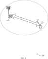
- FIG. 2 illustrates an example of a wireless communication system 200 that supports SPS management in NR in accordance with the invention.
- wireless communication system 200 may implement aspects of wireless communication system 100.
- wireless devices may support communications over carrier 205.
- the wireless communication system 200 may be a 5G or NR system that supports SPS for uplink and downlink communications.
- the base station 105-a may schedule UE 115-a to transmit uplink messages on reserved resources.
- the UE 115-a may receive resource allocation information on PDCCH. More specifically, the UE 115-a may receive the PDCCH included a PDSCH.
- the UE 115-a receives an indication to activate an SPS configuration. In some cases, the indication to activate the SPS may be received via a DCI. In some cases, the DCI may be transmitted by the base station 105-a over carrier 205.
- the UE 115-a may activate the SPS configuration for transmission between the base station 105-a and the UE 115-a.
- the SPS configuration may be activated according to a scheduling DCI included in the PDCCH.
- the UE 115-a is configured to determine a HARQ timing.
- the HARQ timing may be predetermined.
- the UE 115-a may be configured to assume a latency value (or HARQ timing) for transmitting ACK/NACKs in response to a downlink transmission.
- the UE 115-a may receive an initial DCI from the base station 105-a instructing an activation of SPS configuration.
- the initial DCI may be a part of the PDCCH.
- the initial DCI may include an initial HARQ timing.
- the UE 115-a may thus receive a DCI and may identify the HARQ timing indicated by the DCI.
- the UE 115-a may use the determined HARQ timing for transmitting ACK/NACKs associated with the initial DCI.
- the UE 115-a may transmit a feedback (in form of ACK or NACK) to the base station 105-a indicating whether the initial DCI was successfully decoded. This feedback may be transmitted after a timing latency indicated by the HARQ timing in the initial DCI.
- the UE 115-a may be configured to transmit uplink messages to the base station 105-a according to a periodicity set by the SPS configuration. In such cases, the UE 115-a may not receive a scheduling DCI for every subsequent transmission. In some examples, for subsequent transmissions without a scheduling DCI, the UE 115-a may use a predetermined HARQ timing value. In some examples, the predetermined HARQ timing value may be dependent on a UE capability. As previously discussed, the UE capability may be based on a capability profile.
- a HARQ timing value for transmitting feedback associated with SPS transmissions is configured by RRC signaling.
- the UE 115-a may receive an RRC signal from the base station 105-a.
- the RRC signal may indicate an initiating of transmissions according to a received SPS configuration.
- the UE 115-a receives the HARQ timing in the RRC signaling.
- the UE 115-a may use a timing latency indicated by the HARQ timing value to provide feedback to the base station 105-a.
- the UE 115-a may be configured to set up the HARQ timing based on the RRC signaling and a capability associated with the UE 115-a.
- the capability may be based on a minimum value of the HARQ timing supported by the UE 115-a.
- the capability of the UE 115-a may be static.
- a HARQ timing for SPS transmissions without a scheduling DCI may be configured by the most recent DCI activating the SPS.
- the UE 115-a may receive a DCI from the base station 105-a. indicating activation of SPS configuration for transmission between the base station and the UE.
- the UE 115-a may receive an initial HARQ timing in the DCI activating the SPS configuration.
- the UE 115-a may then be configured to use the received HARQ timing for subsequent transmissions without a scheduling DCI.
- the UE 115-a may continue to use the HARQ timing value until the HARQ timing value is updated by the base station 105-a.
- the HARQ timing value may be updated by the base station 105-a by a second activation DCI.
- FIG. 3 illustrates an example of a wireless communication system 300 that supports SPS management in NR useful for understanding the invention.
- the wireless communication system 300 may implement aspects of wireless communication system 100 and wireless communication system 200, as described with reference to FIGs. 1 and 2 .
- the base station 105-b and the UE 115-b may establish a connection (not shown).
- the connection may have one or more wideband CCs.
- one or more of the CCs may include one or more BWPs.
- a CC may include two or more BWPs.
- the base station 105-a may configure the connection 305 with two or more BWPs, and may activate and deactivate one or more of the BWPs through DCI signaling.
- the UE 115-b may receive a signal to activate a first BWP and a second BWP may be inactive by default.
- the base station 105-b may activate the second BWP through transmitting DCI to the UE 115-a that indicates the second BWP is to be activated.
- the UE 115-b may receive the DCI and, in some cases, acknowledge receipt of the DCI. In some cases, the UE 115-b may acknowledge the receipt of the DCI after a timing latency indicated by HARQ timing.
- one or more BWPs may be activated by the base station 105-b via a scheduling DCI, that is transmitted to the UE 115-b.
- multiple BWPs may be configured, and the DCI may include an indication of which BWPs are active for a particular transmission or for a predetermined time period.
- the UE 115-b upon receiving the DCI, may activate the BWP indicated as active, and deactivate any previously active BWPs that are no longer indicated as being active.
- the base station 105-b may transmit a BWP DCI on an active beam to UE 115-b via beamformed transmission 320.
- the UE 115 may receive an indication of SPS resources associated with an active BWP.
- the base station 105-b may be configured to determine SPS configurations and several BWPs to be associated with the SPS configuration.
- the base station 105-b may configure a set of BWPs or other resources in which an SPS configuration may be supported.
- the base station 105-b may configure all BWPs to support SPS configuration.
- the base station 105-b may configure a subset of the BWPs to support SPS configuration.
- the base station 105-b may pre-configure resources for SPS configuration on the BWPs.
- SPS resources may be included within one BWP, but may not be included within another BWP. In such cases, if an active BWP is not pre-configured to support SPS, the UE 115-b may consider that the SPS is implicitly released.
- the base station 105-b may transmit to the UE 115-b, an indication to switch BWPs.
- the LTE 115-b may transmit or receive using SPS configurations associated with the second BWP.
- the base station 105-b may indicate information associated with SPS configurations in the signal indicating switching of the BWPs.
- the SPS periodicity and offsets may be configured separately for each BWP.
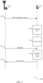
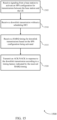
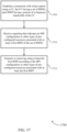
- FIG. 4 illustrates an example of a process flow 400 that supports SPS management in NR in accordance with the invention.
- process flow 400 may implement aspects of wireless communication system 100.
- Base station 105-c may be an example of base station 105, as described with reference to FIG. 1 .
- UE 115-c may be an example of UE 115, as described with reference to FIG. 1 .
- the operations between the base station 105-c and UE 115-c may be transmitted in a different order than the exemplary order shown, or the operations performed by the base station 105-c and UE 115-c may be performed in different orders or at different times. Some operations may also be left out of the process flow 400, or other operations may be added to the process flow 400.
- base station 105-c transmits a signal to activate an SPS configuration for transmission between the base station 105-c and the UE 115-c as described with reference to FIGs. 1 and 2 .
- the signal may be a PDCCH signal including a DCI indicating information associated with the SPS configuration.
- the DCI may indicate initiation of an SPS configuration, periodicity of upcoming SPS transmissions, etc.
- the UE 115-c may determine the DCI included in the signal.
- the UE 115-c may receive an initial HARQ timing as part of the signaling.
- the HARQ timing may be for transmitting feedback associated with the DCI.
- the HARQ timing may be used by the UE 115-c to transmit feedback in response to subsequent downlink transmissions without a scheduling DCI.
- the UE 115-c may activate SPS configuration for transmissions between the base station 105-c and the UE 115-c.
- the UE 115-c may receive downlink transmissions from the base station 105-c.
- the UE 115-c determines a HARQ timing to provide feedback associated with the downlink transmission.
- the HARQ timing value may be predetermined.
- the UE 115-c may predetermine the HARQ timing value based on a UE capability.
- the HARQ timing value is indicated by RRC signaling (not shown).
- the HARQ timing value may be the value indicated in the DCI received by the UE 115-c at 405. In such cases, the UE 115-c may continue to use the HARQ timing value associated with the DCI until the DCI is updated.
- the UE 115-c may transmit an ACK/NACK in response to the downlink transmission according to a timing latency indicated by the received HARQ timing.
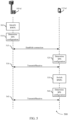
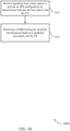
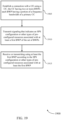
- FIG. 5 illustrates an example of a process flow 500 that supports SPS management in NR useful for understanding the invention.
- process flow 500 may implement aspects of wireless communication system 100.
- Base station 105-d may be an example of base station 105, as described with reference to FIG. 1 .
- UE 115-d may be an example of UE 115, as described with reference to FIG. 1 .
- the operations between the base station 105-d and UE 115-d may be transmitted in a different order than the exemplary order shown, or the operations performed by the base station 105-d and UE 115-d may be performed in different orders or at different times. Some operations may also be left out of the process flow 500, or other operations may be added to the process flow 500.
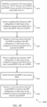
- the base station 105-d may identify a plurality of BWPs.
- each BWP may include a portion of a frequency bandwidth of a primary CC.
- a first BWP may include a first range of frequencies and a second BWP may include a second range of frequencies, where the first range of frequencies do not overlap with the second range of frequencies.
- the base station 105-d may identify a subset of BWPs from the plurality of BWPs and associate the subset of BWPs with an SPS configuration.
- the base station 105-d and the UE 115-d may establish a connection with each other using a CC.
- the CC having a plurality of BWPs.
- the UE 115-d may receive a signaling that indicates the SPS configuration or other types of pre-configured resources associated with a BWP.
- the signaling may include DCI and RRC messages.
- the UE 115-d may activate a BWP and may determine the SPS configurations associated with the activated BWP. In some cases, the UE 115-d may determine other types of pre-configured resources associated with the activated BWP.
- the UE 115-d and the base station 105-d may transmit or receive using the activated BWP according to the SPS configuration or other types of pre-configured resources associated with the activated BWP.
- the UE 115-d may switch from a first BWP to a second BWP. In some cases, the switching may be in response to a signaling that indicates a SPS configuration or other types of pre-configured resources associated with the second BWP (not shown).
- the UE 115-d may determine SPS configuration information associated with the second BWP. In some cases, the UE 115-d may determine other types of pre-configured resources associated with the second BWP.
- the UE 115-d may transmit or receive using the second BWP according to the determined SPS configuration or other types of pre-configured resources associated with the second BWP.
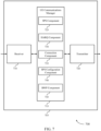
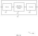
- FIG. 6 shows a block diagram 600 of a wireless device 605 that supports SPS management in NR in accordance with the invention .
- Wireless device 605 may be an example of aspects of a UE 115 as described herein.
- Wireless device 605 may include receiver 610, UE communications manager 615, and transmitter 620.
- Wireless device 605 may also include a processor. Each of these components may be in communication with one another (e.g., via one or more buses).
- Receiver 610 may receive information such as packets, user data, or control information associated with various information channels (e.g., control channels, data channels, and information related to SPS management in NR, etc.). Information may be passed on to other components of the device.
- the receiver 610 may be an example of aspects of the transceiver 935 described with reference to FIG. 9 .
- the receiver 610 may utilize a single antenna or a set of antennas.
- Receiver 610 may receive a downlink transmission without a scheduling DCI.
- UE communications manager 615 may be an example of aspects of the UE communications manager 915 described with reference to FIG. 9 .
- UE communications manager 615 and/or at least some of its various sub-components may be implemented in hardware, software executed by a processor, firmware, or any combination thereof. If implemented in software executed by a processor, the functions of the UE communications manager 615 and/or at least some of its various sub-components may be executed by a general-purpose processor, a digital signal processor (DSP), an application-specific integrated circuit (ASIC), an field-programmable gate array (FPGA) or other programmable logic device, discrete gate or transistor logic, discrete hardware components, or any combination thereof designed to perform the functions described in the present disclosure.
- DSP digital signal processor
- ASIC application-specific integrated circuit
- FPGA field-programmable gate array
- the UE communications manager 615 and/or at least some of its various sub-components may be physically located at various positions, including being distributed such that portions of functions are implemented at different physical locations by one or more physical devices.
- UE communications manager 615 and/or at least some of its various sub-components may be a separate and distinct component in accordance with various aspects of the present disclosure.
- UE communications manager 615 and/or at least some of its various sub-components may be combined with one or more other hardware components, including but not limited to an I/O component, a transceiver, a network server, another computing device, one or more other components described in the present disclosure, or a combination thereof in accordance with various aspects of the present disclosure.
- UE communications manager 615 receives signaling from a base station to activate an SPS configuration for transmission between the base station and the UE, and receives a HARQ timing for downlink transmissions based on the SPS configuration being activated.
- the UE communications manager 615 may also receive signaling from a base station to activate an SPS configuration for transmission between the base station and the UE and determine a HARQ timing for downlink transmissions based on a capability associated with the UE.
- the UE communications manager 615 may also establish a connection with a base station using a CC, the CC having a set of BWPs, each BWP having a portion of a frequency bandwidth of the CC.
- the UE communications manager 615 may receive signaling that indicates an SPS configuration or other types of pre-configured resources associated with at least a first BWP of the set of BWPs, and transmit or receive using at least the first BWP according to the SPS configuration or other types of pre-configured resources associated with at least the first BWP.
- Transmitter 620 may transmit signals generated by other components of the device.
- the transmitter 620 may be collocated with a receiver 610 in a transceiver module.
- the transmitter 620 may be an example of aspects of the transceiver 935 described with reference to FIG. 9 .
- the transmitter 620 may utilize a single antenna or a set of antennas.
- Transmitter 620 may transmit an ACK/NACK in response to the downlink transmission according to a timing latency indicated by the received HARQ timing.
- FIG. 7 shows a block diagram 700 of a wireless device 705 that supports SPS management in accordance with the invention.
- Wireless device 705 may be an example of aspects of a wireless device 605 or a UE 115 as described with reference to FIG. 6 .
- Wireless device 705 may include receiver 710, UE communications manager 715, and transmitter 720.
- Wireless device 705 may also include a processor. Each of these components may be in communication with one another (e.g., via one or more buses).
- Receiver 710 may receive information such as packets, user data, or control information associated with various information channels (e.g., control channels, data channels, and information related to SPS management in NR, etc.). Information may be passed on to other components of the device.
- the receiver 710 may be an example of aspects of the transceiver 935 described with reference to FIG. 9 .
- the receiver 710 may utilize a single antenna or a set of antennas.
- UE communications manager 715 may be an example of aspects of the UE communications manager 915 described with reference to FIG. 9 .
- UE communications manager 715 may also include SPS component 725, HARQ component 730, connection component 735, SPS configuration component 740, and BWP component 745.
- SPS component 725 receives signaling from a base station to activate an SPS configuration for transmission between the base station and the UE and may receive signaling from the base station to activate a second SPS configuration for a second set of transmissions between the base station and the UE.
- the HARQ component 730 receives a HARQ timing for downlink transmissions based on the SPS configuration being activated.
- the HARQ component 730 may receive a second HARQ timing via RRC signaling.
- the second HARQ timing may be associated with the second SPS configuration.
- the HARQ component may also receive the HARQ timing via the activation DCI, the activation DCI including a PDSCH, and determine a HARQ timing for downlink transmissions based on a capability associated with the UE (such as UE 115).
- the received HARQ timing is applied to the PDSCH with the activation DCI and subsequent transmissions of PDSCH without a DCI.
- the HARQ timing is a function of at least one of a slot structure, or a BWP switching procedure, or a combination thereof. In some cases, the HARQ timing is a function of at least one of a slot structure and a BWP switching procedure.
- Connection component 735 may establish a connection with a base station using a CC, the CC having a set of BWPs, each BWP having a portion of a frequency bandwidth of the CC.
- SPS configuration component 740 may receive signaling that indicates an SPS configuration or other types of pre-configured resources associated with at least a first BWP of the set of BWPs.
- the SPS configuration component 740 may receive signaling that indicates a SPS configuration or other types of pre-configured resources associated with at least a second BWP of the set of BWPs.
- the SPS configuration component 740 may determine the second BWP is unassociated with an SPS configuration or other types of pre-configured resources.
- the signaling includes DCI or RRC messages.
- BWP component 745 may transmit or receive using at least the first BWP according to the SPS configuration or other types of pre-configured resources associated with at least the first BWP. In some cases, the BWP component 745 may transmit or receive using at least the second BWP according to the SPS configuration or other types of pre-configured resources associated with at least the second BWP. In some cases, the BWP component may transmit or receive using the second BWP and without an active SPS configuration.
- Transmitter 720 may transmit signals generated by other components of the device.
- the transmitter 720 may be collocated with a receiver 710 in a transceiver module.
- the transmitter 720 may be an example of aspects of the transceiver 935 described with reference to FIG. 9 .
- the transmitter 720 may utilize a single antenna or a set of antennas.
- FIG. 8 shows a block diagram 800 of a UE communications manager 815 that supports SPS management in NR in accordance with the invention.
- the UE communications manager 815 may be an example of aspects of a UE communications manager 615, a UE communications manager 715, or a UE communications manager 915 described with reference to FIGs. 6 , 7 , and 9 .
- the UE communications manager 815 may include SPS component 820, HARQ component 825, connection component 830, SPS configuration component 835, BWP component 840, RRC component 845, UE capability component 850, DCI component 855, slot structure component 860, and switching component 865. Each of these modules may communicate, directly or indirectly, with one another (e.g., via one or more buses).
- SPS component 820 receives signaling from a base station to activate an SPS configuration for transmission between the base station and the UE, and may receive signaling from the base station to activate a second SPS configuration for a second set of transmissions between the base station and the UE.
- the HARQ component 825 receives a HARQ timing for downlink transmissions based on the SPS configuration being activated. In some cases, the HARQ component 825 may receive a second HARQ timing via the RRC signaling, the second HARQ timing being associated with the second SPS configuration. In some implementations, the HARQ component 825 may receive the HARQ timing via the activation DCI, the activation DCI including a PDSCH, and determine a HARQ timing for downlink transmissions based on a capability associated with the UE. In some cases, the received HARQ timing is applied to the PDSCH with the activation DCI and subsequent transmissions of PDSCH without a DCI. In some cases, the HARQ timing is a function of at least one of: a slot structure, a BWP switching procedure, or a combination thereof.
- Connection component 830 may establish a connection with a base station using a CC, the CC having a set of BWPs, each BWP having a portion of a frequency bandwidth of the CC.
- SPS configuration component 835 may receive signaling that indicates an SPS configuration or other types of pre-configured resources associated with at least a first BWP of the set of BWPs, receive signaling that indicates a SPS configuration or other types of pre-configured resources associated with at least a second BWP of the set of BWPs, and determine the second BWP is unassociated with an SPS configuration or other types of pre-configured resources.
- the signaling includes DCI or RRC messages.
- BWP component 840 may transmit or receive using at least the first BWP according to the SPS configuration or other types of pre-configured resources associated with at least the first BWP. In some cases, the BWP component 840 may transmit or receive using at least the second BWP according to the SPS configuration or other types of pre-configured resources associated with at least the second BWP. In some cases, the BWP component 840 may transmit or receive using the second BWP and without an active SPS configuration.
- RRC component 845 may receive an RRC signaling from the base station.
- receiving the HARQ timing may include receiving the HARQ timing via the RRC signaling from the base station.
- UE capability component 850 may determine a capability of the UE (such as UE 115).
- the HARQ timing is based on the capability of the UE.
- the capability associated with the UE is based on a capability profile for the UE, where the capability profile indicates a minimum value of the HARQ timing supported by the UE.
- the capability associated with the UE is static.
- DCI component 855 may receive a second activation DCI that includes second HARQ timing, the second HARQ timing replacing the previously received HARQ timing.
- the signaling to activate the SPS configuration includes an activation DCI.
- the received signaling to activate the SPS configuration includes an activation DCI.
- Slot structure component 860 may determine a slot structure.
- the slot structure includes an uplink transmission opportunity for transmitting an ACK/NACK in response to a downlink transmission.
- the slot structure is dynamically indicated by at least one SFI.
- Switching component 865 may switch from the first BWP to the second BWP and switch from the first BWP to a second BWP.
- FIG. 9 shows a diagram of a system 900 including a device 905 that supports SPS management in NR useful for understanding the invention.
- Device 905 may be an example of or include the components of wireless device 605, wireless device 705, or a UE 115 as described above, e.g., with reference to FIGs. 6 and 7 .
- Device 905 may include components for bi-directional voice and data communications including components for transmitting and receiving communications, including UE communications manager 915, processor 920, memory 925, software 930, transceiver 935, antenna 940, and I/O controller 945. These components may be in electronic communication via one or more buses (e.g., bus 910).
- Device 905 may communicate wirelessly with one or more base stations 105.
- Processor 920 may include an intelligent hardware device, (e.g., a general-purpose processor, a DSP, a central processing unit (CPU), a microcontroller, an ASIC, an FPGA, a programmable logic device, a discrete gate or transistor logic component, a discrete hardware component, or any combination thereof).
- processor 920 may be configured to operate a memory array using a memory controller.
- a memory controller may be integrated into processor 920.
- Processor 920 may be configured to execute computer-readable instructions stored in a memory to perform various functions (e.g., functions or tasks supporting SPS management in NR).
- Memory 925 may include random access memory (RAM) and read only memory (ROM).
- the memory 925 may store computer-readable, computer-executable software 930 including instructions that, when executed, cause the processor to perform various functions described herein.
- the memory 925 may contain, among other things, a basic input/output system (BIOS) which may control basic hardware or software operation such as the interaction with peripheral components or devices.
- BIOS basic input/output system
- Software 930 may include code to implement aspects of the present disclosure, including code to support SPS management in NR.
- Software 930 may be stored in a non-transitory computer-readable medium such as system memory or other memory. In some cases, the software 930 may not be directly executable by the processor but may cause a computer (e.g., when compiled and executed) to perform functions described herein.
- Transceiver 935 may communicate bi-directionally, via one or more antennas, wired, or wireless links as described above.
- the transceiver 935 may represent a wireless transceiver and may communicate bi-directionally with another wireless transceiver.
- the transceiver 935 may also include a modem to modulate the packets and provide the modulated packets to the antennas for transmission, and to demodulate packets received from the antennas.
- the wireless device may include a single antenna 940. However, in some cases the device may have more than one antenna 940, which may be capable of concurrently transmitting or receiving multiple wireless transmissions.
- I/O controller 945 may manage input and output signals for device 905. I/O controller 945 may also manage peripherals not integrated into device 905. In some cases, I/O controller 945 may represent a physical connection or port to an external peripheral. In some cases, I/O controller 945 may utilize an operating system such as iOS ® , ANDROID ® , MS-DOS ® , MS-WINDOWS ® , OS/2 ® , UNIX ® , LINUX ® , or another known operating system. In other cases, I/O controller 945 may represent or interact with a modem, a keyboard, a mouse, a touchscreen, or a similar device. In some cases, I/O controller 945 may be implemented as part of a processor. In some cases, a user may interact with device 905 via I/O controller 945 or via hardware components controlled by I/O controller 945.
- FIG. 10 shows a block diagram 1000 of a wireless device 1005 that supports SPS management in NR useful for understanding the invention.
- Wireless device 1005 may be an example of aspects of a base station 105 as described herein.
- Wireless device 1005 may include receiver 1010, base station communications manager 1015, and transmitter 1020.
- Wireless device 1005 may also include a processor. Each of these components may be in communication with one another (e.g., via one or more buses).
- Receiver 1010 may receive information such as packets, user data, or control information associated with various information channels (e.g., control channels, data channels, and information related to SPS management in NR, etc.). Information may be passed on to other components of the device.
- the receiver 1010 may be an example of aspects of the transceiver 1335 described with reference to FIG. 13 .
- the receiver 1010 may utilize a single antenna or a set of antennas.
- Base station communications manager 1015 may be an example of aspects of the base station communications manager 1315 described with reference to FIG. 13 .
- Base station communications manager 1015 and/or at least some of its various sub-components may be implemented in hardware, software executed by a processor, firmware, or any combination thereof. If implemented in software executed by a processor, the functions of the base station communications manager 1015 and/or at least some of its various sub-components may be executed by a general-purpose processor, a DSP, an ASIC, an FPGA or other programmable logic device, discrete gate or transistor logic, discrete hardware components, or any combination thereof designed to perform the functions described in the present disclosure.
- the base station communications manager 1015 and/or at least some of its various sub-components may be physically located at various positions, including being distributed such that portions of functions are implemented at different physical locations by one or more physical devices.
- base station communications manager 1015 and/or at least some of its various sub-components may be a separate and distinct component in accordance with various aspects of the present disclosure.
- base station communications manager 1015 and/or at least some of its various sub-components may be combined with one or more other hardware components, including but not limited to an I/O component, a transceiver, a network server, another computing device, one or more other components described in the present disclosure, or a combination thereof in accordance with various aspects of the present disclosure.
- Base station communications manager 1015 may establish a connection with a UE using a CC, the CC having two or more BWPs. In some cases, each BWP may have a portion of a frequency bandwidth of a primary CC.
- the base station communications manager 1015 may transmit signaling that indicates an SPS configuration or other types of pre-configured resources associated with at least a first BWP of the set of BWPs, and receive or transmitting using at least the first BWP according to the SPS configuration or other types of pre-configured resources associated with at least the first BWP.
- Transmitter 1020 may transmit signals generated by other components of the device.
- the transmitter 1020 may be collocated with a receiver 1010 in a transceiver module.
- the transmitter 1020 may be an example of aspects of the transceiver 1335 described with reference to FIG. 13 .
- the transmitter 1020 may utilize a single antenna or a set of antennas.
- FIG. 11 shows a block diagram 1100 of a wireless device 1105 that supports SPS management in NR useful for understanding the invention.
- Wireless device 1105 may be an example of aspects of a wireless device 1005 or a base station 105 as described with reference to FIG. 10 .
- Wireless device 1105 may include receiver 1110, base station communications manager 1115, and transmitter 1120.
- Wireless device 1105 may also include a processor. Each of these components may be in communication with one another (e.g., via one or more buses).
- Receiver 1110 may receive information such as packets, user data, or control information associated with various information channels (e.g., control channels, data channels, and information related to SPS management in NR, etc.). Information may be passed on to other components of the device.
- the receiver 1110 may be an example of aspects of the transceiver 1335 described with reference to FIG. 13 .
- the receiver 1110 may utilize a single antenna or a set of antennas.
- Base station communications manager 1115 may be an example of aspects of the base station communications manager 1315 described with reference to FIG. 13 .
- Base station communications manager 1115 may also include connection component 1125, SPS configuration component 1130, and BWP component 1135.
- Connection component 1125 may establish a connection with a UE using a CC, the CC having two or more BWPs each BWP having a portion of a frequency bandwidth of a primary CC.
- SPS configuration component 1130 may transmit signaling that indicates an SPS configuration or other types of pre-configured resources associated with at least a first BWP of the set of BWPs. In some cases, the signaling includes DCI or RRC messages.
- BWP component 1135 may receive or transmit using at least the first BWP according to the SPS configuration or other types of pre-configured resources associated with at least the first BWP and identify a subset of BWPs from the set of BWPs that are to be associated with an SPS configuration.
- Transmitter 1120 may transmit signals generated by other components of the device.
- the transmitter 1120 may be collocated with a receiver 1110 in a transceiver module.
- the transmitter 1120 may be an example of aspects of the transceiver 1335 described with reference to FIG. 13 .
- the transmitter 1120 may utilize a single antenna or a set of antennas.
- FIG. 12 shows a block diagram 1200 of a base station communications manager 1215 that supports SPS management in NR useful for understanding the invention.
- the base station communications manager 1215 may be an example of aspects of a base station communications manager 1315 described with reference to FIGs. 10 , 11 , and 13 .
- the base station communications manager 1215 may include connection component 1220, SPS configuration component 1225, and BWP component 1230. Each of these modules may communicate, directly or indirectly, with one another (e.g., via one or more buses).
- Connection component 1220 may establish a connection with a UE using a CC, the CC having two or more BWPs, each BWP having a portion of a frequency bandwidth of a primary CC.
- SPS configuration component 1225 may transmit signaling that indicates an SPS configuration or other types of pre-configured resources associated with at least a first BWP of the set of BWPs. In some cases, the signaling includes DCI or RRC messages.
- BWP component 1230 may receive or transmit using at least the first BWP according to the SPS configuration or other types of pre-configured resources associated with at least the first BWP and identify a subset of BWPs from the set of BWPs that are to be associated with an SPS configuration.
- FIG. 13 shows a diagram of a system 1300 including a device 1305 that supports SPS management in NR useful for understanding the invention.
- Device 1305 may be an example of or include the components of base station 105 as described above, e.g., with reference to FIG. 1 .
- Device 1305 may include components for bi-directional voice and data communications including components for transmitting and receiving communications, including base station communications manager 1315, processor 1320, memory 1325, software 1330, transceiver 1335, antenna 1340, network communications manager 1345, and inter-station communications manager 1350. These components may be in electronic communication via one or more buses (e.g., bus 1310).
- Device 1305 may communicate wirelessly with one or more UEs 115.
- Processor 1320 may include an intelligent hardware device, (e.g., a general-purpose processor, a DSP, a CPU, a microcontroller, an ASIC, an FPGA, a programmable logic device, a discrete gate or transistor logic component, a discrete hardware component, or any combination thereof).
- processor 1320 may be configured to operate a memory array using a memory controller.
- a memory controller may be integrated into processor 1320.
- Processor 1320 may be configured to execute computer-readable instructions stored in a memory to perform various functions (e.g., functions or tasks supporting SPS management in NR).
- Memory 1325 may include RAM and ROM.
- the memory 1325 may store computer-readable, computer-executable software 1330 including instructions that, when executed, cause the processor to perform various functions described herein.
- the memory 1325 may contain, among other things, a BIOS which may control basic hardware or software operation such as the interaction with peripheral components or devices.
- Software 1330 may include code to implement aspects of the present disclosure, including code to support SPS management in NR.
- Software 1330 may be stored in a non-transitory computer-readable medium such as system memory or other memory. In some cases, the software 1330 may not be directly executable by the processor but may cause a computer (e.g., when compiled and executed) to perform functions described herein.
- Transceiver 1335 may communicate bi-directionally, via one or more antennas, wired, or wireless links as described above.
- the transceiver 1335 may represent a wireless transceiver and may communicate bi-directionally with another wireless transceiver.
- the transceiver 1335 may also include a modem to modulate the packets and provide the modulated packets to the antennas for transmission, and to demodulate packets received from the antennas.
- the wireless device may include a single antenna 1340. However, in some cases the device may have more than one antenna 1340, which may be capable of concurrently transmitting or receiving multiple wireless transmissions.
- Network communications manager 1345 may manage communications with the core network (e.g., via one or more wired backhaul links). For example, the network communications manager 1345 may manage the transfer of data communications for client devices, such as one or more UEs 115.
- Inter-station communications manager 1350 may manage communications with other base station 105 and may include a controller or scheduler for controlling communications with UEs 115 in cooperation with other base stations 105. For example, the inter-station communications manager 1350 may coordinate scheduling for transmissions to UEs 115 for various interference mitigation techniques such as beamforming or joint transmission. In some examples, inter-station communications manager 1350 may provide an X2 interface within an LTE/LTE-A wireless communication network technology to provide communication between base stations 105.
- FIG. 14 shows a flowchart illustrating a method 1400 for SPS management in NR in accordance with the invention.
- the operations of method 1400 may be implemented by a UE 115 or its components as described herein.
- the operations of method 1400 may be performed by a UE communications manager as described with reference to FIGs. 6 through 9 .
- a UE 115 may execute a set of codes to control the functional elements of the device to perform the functions described below. Additionally, or alternatively, the UE 115 may perform aspects of the functions described below using special-purpose hardware.
- the UE 115 receives signaling from a base station to activate an SPS configuration for transmission between the base station and the UE.
- the operations of 1405 may be performed according to the methods described herein. In some examples, aspects of the operations of 1405 may be performed by a SPS component as described with reference to FIGs. 6 through 9 .
- the UE 115 receives a HARQ timing for downlink transmissions based on the SPS configuration being activated.
- the operations of 1410 may be performed according to the methods described herein. In some examples, aspects of the operations of 1410 may be performed by a HARQ component as described with reference to FIGs. 6 through 9 .
- FIG. 15 shows a flowchart illustrating a method 1500 for SPS management in NR in accordance with aspects of the present disclosure.
- the operations of method 1500 may be implemented by a UE 115 or its components as described herein.
- the operations of method 1500 may be performed by a UE communications manager as described with reference to FIGs. 6 through 9 .
- a UE 115 may execute a set of codes to control the functional elements of the device to perform the functions described below. Additionally, or alternatively, the UE 115 may perform aspects of the functions described below using special-purpose hardware.
- the UE 115 receives signaling from a base station to activate an SPS configuration for transmission between the base station and the UE.
- the operations of 1505 may be performed according to the methods described herein. In some examples, aspects of the operations of 1505 may be performed by a SPS component as described with reference to FIGs. 6 through 9 .
- the UE 115 may receive a downlink transmission without a scheduling DCI.
- the operations of 1510 may be performed according to the methods described herein. In some examples, aspects of the operations of 1510 may be performed by a receiver as described with reference to FIGs. 6 through 9 .
- the UE 115 receives a HARQ timing for downlink transmissions based on the SPS configuration being activated.
- the operations of 1515 may be performed according to the methods described herein. In some examples, aspects of the operations of 1515 may be performed by a HARQ component as described with reference to FIGs. 6 through 9 .
- the UE 115 may transmit an ACK/NACK in response to the downlink transmission according to a timing latency indicated by the received HARQ timing.
- the operations of 1520 may be performed according to the methods described herein. In some examples, aspects of the operations of 1520 may be performed by a transmitter as described with reference to FIGs. 6 through 9 .
- FIG. 16 shows a flowchart illustrating a method 1600 for SPS management in NR in accordance with the invention.
- the operations of method 1600 may be implemented by a UE 115 or its components as described herein.
- the operations of method 1600 may be performed by a UE communications manager as described with reference to FIGs. 6 through 9 .
- a UE 115 may execute a set of codes to control the functional elements of the device to perform the functions described below. Additionally, or alternatively, the UE 115 may perform aspects of the functions described below using special-purpose hardware.
- the UE 115 receives signaling from a base station to activate an SPS configuration for transmission between the base station and the UE.
- the operations of 1605 may be performed according to the methods described herein. In some examples, aspects of the operations of 1605 may be performed by a SPS component as described with reference to FIGs. 6 through 9 .
- the UE 115 determines a HARQ timing for downlink transmissions based on a capability associated with the UE.
- the operations of 1610 may be performed according to the methods described herein. In some examples, aspects of the operations of 1610 may be performed by a HARQ component as described with reference to FIGs. 6 through 9 .
- FIG. 17 shows a flowchart illustrating a method 1700 for SPS management in NR useful for understanding the invention.
- the operations of method 1700 may be implemented by a UE 115 or its components as described herein.
- the operations of method 1700 may be performed by a UE communications manager as described with reference to FIGs. 6 through 9 .
- a UE 115 may execute a set of codes to control the functional elements of the device to perform the functions described below. Additionally, or alternatively, the UE 115 may perform aspects of the functions described below using special-purpose hardware.
- the UE 115 may establish a connection with a base station using a CC, the CC having a plurality of BWPs, each BWP having a portion of a frequency bandwidth of the CC.
- the operations of 1705 may be performed according to the methods described herein. In some examples, aspects of the operations of 1705 may be performed by a connection component as described with reference to FIGs. 6 through 9 .
- the UE 115 may receive signaling that indicates an SPS configuration or other types of pre-configured resources associated with at least a first BWP of the plurality of BWPs.
- the operations of 1710 may be performed according to the methods described herein. In some examples, aspects of the operations of 1710 may be performed by a SPS configuration component as described with reference to FIGs. 6 through 9 .
- the UE 115 may transmit or receiving using at least the first BWP according to the SPS configuration or other types of pre-configured resources associated with at least the first BWP.
- the operations of 1715 may be performed according to the methods described herein. In some examples, aspects of the operations of 1715 may be performed by a BWP component as described with reference to FIGs. 6 through 9 .
- FIG. 18 shows a flowchart illustrating a method 1800 for SPS management in NR useful for understanding the invention.
- the operations of method 1800 may be implemented by a UE 115 or its components as described herein.
- the operations of method 1800 may be performed by a UE communications manager as described with reference to FIGs. 6 through 9 .
- a UE 115 may execute a set of codes to control the functional elements of the device to perform the functions described below. Additionally, or alternatively, the UE 115 may perform aspects of the functions described below using special-purpose hardware.
- the UE 115 may establish a connection with a base station using a CC, the CC having a plurality of BWPs, each BWP having a portion of a frequency bandwidth of the CC.
- the operations of 1805 may be performed according to the methods described herein. In some examples, aspects of the operations of 1805 may be performed by a connection component as described with reference to FIGs. 6 through 9 .
- the UE 115 may receive signaling that indicates an SPS configuration or other types of pre-configured resources associated with at least a first BWP of the plurality of BWPs.
- the operations of 1810 may be performed according to the methods described herein. In some examples, aspects of the operations of 1810 may be performed by a SPS configuration component as described with reference to FIGs. 6 through 9 .
- the UE 115 may transmit or receiving using at least the first BWP according to the SPS configuration or other types of pre-configured resources associated with at least the first BWP.
- the operations of 1815 may be performed according to the methods described herein. In some examples, aspects of the operations of 1815 may be performed by a BWP component as described with reference to FIGs. 6 through 9 .
- the UE 115 may receive signaling that indicates a SPS configuration or other types of pre-configured resources associated with at least a second BWP of the plurality of BWPs.
- the operations of 1820 may be performed according to the methods described herein. In some examples, aspects of the operations of 1820 may be performed by a SPS configuration component as described with reference to FIGs. 6 through 9 .
- the UE 115 may switch from the first BWP to the second BWP.
- the operations of 1825 may be performed according to the methods described herein. In some examples, aspects of the operations of 1825 may be performed by a switching component as described with reference to FIGs. 6 through 9 .
- the UE 115 may transmit or receiving using at least the second BWP according to the SPS configuration or other types of pre-configured resources associated with at least the second BWP.
- the operations of 1830 may be performed according to the methods described herein. In some examples, aspects of the operations of 1830 may be performed by a BWP component as described with reference to FIGs. 6 through 9 .
- FIG. 19 shows a flowchart illustrating a method 1900 for SPS management in NR useful for understanding the invention.
- the operations of method 1900 may be implemented by a base station 105 or its components as described herein.
- the operations of method 1900 may be performed by a base station communications manager as described with reference to FIGs. 10 through 13 .
- a base station 105 may execute a set of codes to control the functional elements of the device to perform the functions described below. Additionally, or alternatively, the base station 105 may perform aspects of the functions described below using special-purpose hardware.
- the base station 105 may establish a connection with a UE using a CC, the CC having two or more BWPs each BWP having a portion of a frequency bandwidth of a primary CC.
- the operations of 1905 may be performed according to the methods described herein. In some examples, aspects of the operations of 1905 may be performed by a connection component as described with reference to FIGs. 10 through 13 .
- the base station 105 may transmit signaling that indicates an SPS configuration or other types of pre-configured resources associated with at least a first BWP of the plurality of BWPs.
- the operations of 1910 may be performed according to the methods described herein. In some examples, aspects of the operations of 1910 may be performed by a SPS configuration component as described with reference to FIGs. 10 through 13 .
- the base station 105 may receive or transmitting using at least the first BWP according to the SPS configuration or other types of pre-configured resources associated with at least the first BWP.
- the operations of 1915 may be performed according to the methods described herein. In some examples, aspects of the operations of 1915 may be performed by a BWP component as described with reference to FIGs. 10 through 13 .
- CDMA code division multiple access
- TDMA time division multiple access
- FDMA frequency division multiple access
- OFDMA orthogonal frequency division multiple access
- SC-FDMA single carrier frequency division multiple access
- a CDMA system may implement a radio technology such as CDMA2000, Universal Terrestrial Radio Access (UTRA), etc.
- CDMA2000 covers IS-2000, IS-95, and IS-856 standards.
- IS-2000 Releases may be commonly referred to as CDMA2000 1X, 1X, etc.
- IS-856 TIA-856) is commonly referred to as CDMA2000 1 ⁇ EV-DO, High Rate Packet Data (HRPD), etc.
- UTRA includes Wideband CDMA (WCDMA) and other variants of CDMA.
- a TDMA system may implement a radio technology such as Global System for Mobile Communications (GSM).
- GSM Global System for Mobile Communications
- An OFDMA system may implement a radio technology such as Ultra Mobile Broadband (UMB), Evolved UTRA (E-UTRA), Institute of Electrical and Electronics Engineers (IEEE) 802.11 (Wi-Fi), IEEE 802.16 (WiMAX), IEEE 802.20, Flash-OFDM, etc.
- UMB Ultra Mobile Broadband
- E-UTRA Evolved UTRA
- IEEE Institute of Electrical and Electronics Engineers
- Wi-Fi Wi-Fi
- WiMAX IEEE 802.16
- IEEE 802.20 Flash-OFDM
- UMB Ultra Mobile Broadband
- E-UTRA Evolved UTRA
- IEEE 802.11 Wi-Fi
- WiMAX IEEE 802.16
- Flash-OFDM Flash-OFDM
- UTRA and E-UTRA are part of Universal Mobile Telecommunications System (UMTS).
- LTE and LTE-A are releases of UMTS that use E-UTRA.
- LTE or NR may be described for purposes of example, and LTE or NR terminology may be used in much of the description, the techniques described herein are applicable beyond LTE or NR applications.
- a macro cell generally covers a relatively large geographic area (e.g., several kilometers in radius) and may allow unrestricted access by UEs 115 with service subscriptions with the network provider.
- a small cell may be associated with a lower-powered base station 105, as compared with a macro cell, and a small cell may operate in the same or different (e.g., licensed, unlicensed, etc.) frequency bands as macro cells.
- Small cells may include pico cells, femto cells, and micro cells according to various examples.
- a pico cell for example, may cover a small geographic area and may allow unrestricted access by UEs 115 with service subscriptions with the network provider.
- a femto cell may also cover a small geographic area (e.g., a home) and may provide restricted access by UEs 115 having an association with the femto cell (e.g., UEs 115 in a closed subscriber group (CSG), UEs 115 for users in the home, and the like).
- An eNB for a macro cell may be referred to as a macro eNB.
- An eNB for a small cell may be referred to as a small cell eNB, a pico eNB, a femto eNB, or a home eNB.
- An eNB may support one or multiple (e.g., two, three, four, and the like) cells, and may also support communications using one or multiple component carriers.
- the wireless communications system 100 or systems described herein may support synchronous or asynchronous operation.
- the base stations 105 may have similar frame timing, and transmissions from different base stations 105 may be approximately aligned in time.
- the base stations 105 may have different frame timing, and transmissions from different base stations 105 may not be aligned in time.
- the techniques described herein may be used for either synchronous or asynchronous operations.
- Information and signals described herein may be represented using any of a variety of different technologies and techniques.
- data, instructions, commands, information, signals, bits, symbols, and chips that may be referenced throughout the above description may be represented by voltages, currents, electromagnetic waves, magnetic fields or particles, optical fields or particles, or any combination thereof.
- a general-purpose processor may be a microprocessor, but in the alternative, the processor may be any conventional processor, controller, microcontroller, or state machine.
- a processor may also be implemented as a combination of computing devices (e.g., a combination of a DSP and a microprocessor, multiple microprocessors, one or more microprocessors in conjunction with a DSP core, or any other such configuration).
- the functions described herein may be implemented in hardware, software executed by a processor, firmware, or any combination thereof. If implemented in software executed by a processor, the functions may be stored on or transmitted over as one or more instructions or code on a computer-readable medium. Due to the nature of software, functions described above can be implemented using software executed by a processor, hardware, firmware, hardwiring, or combinations of any of these. Features implementing functions may also be physically located at various positions, including being distributed such that portions of functions are implemented at different physical locations.
- Computer-readable media includes both non-transitory computer storage media and communication media including any medium that facilitates transfer of a computer program from one place to another.
- a non-transitory storage medium may be any available medium that can be accessed by a general purpose or special purpose computer.
- non-transitory computer-readable media may include RAM, ROM, electrically erasable programmable read only memory (EEPROM), flash memory, compact disk (CD) ROM or other optical disk storage, magnetic disk storage or other magnetic storage devices, or any other non-transitory medium that can be used to carry or store desired program code means in the form of instructions or data structures and that can be accessed by a general-purpose or special-purpose computer, or a general-purpose or special-purpose processor.
- any connection is properly termed a computer-readable medium.
- the software is transmitted from a website, server, or other remote source using a coaxial cable, fiber optic cable, twisted pair, digital subscriber line (DSL), or wireless technologies such as infrared, radio, and microwave
- the coaxial cable, fiber optic cable, twisted pair, DSL, or wireless technologies such as infrared, radio, and microwave are included in the definition of medium.
- Disk and disc include CD, laser disc, optical disc, digital versatile disc (DVD), floppy disk and Blu-ray disc where disks usually reproduce data magnetically, while discs reproduce data optically with lasers.
Landscapes
- Engineering & Computer Science (AREA)
- Signal Processing (AREA)
- Computer Networks & Wireless Communication (AREA)
- Mobile Radio Communication Systems (AREA)
- Detection And Prevention Of Errors In Transmission (AREA)
- Communication Control (AREA)
Claims (15)
- Verfahren zum Durchführen einer drahtlosen Kommunikation durch ein Benutzergerät, UE, in einem neuen Funknetz, NR, wobei das Verfahren umfasst:Empfangen (1605) einer Signalisierung von einer Basisstation, um eine semipersistente Scheduling-, SPS-, Konfiguration zu aktivieren, die von einem Bandbreitenteil abhängt, mit dem das UE konfiguriert ist, wobei die SPS-Konfiguration dem UE-Ressourcen, die mit dem Bandbreitenteil verbunden sind, für Übertragungen zwischen der Basisstation und dem UE zuweist; undBestimmen (1610) einer hybriden automatischen Wiederholungsanforderung, HARQ, Zeitsteuerung für Abwärtsstreckenübertragungen, die zumindest teilweise auf der SPS-Konfiguration, die aktiviert ist, und einem HARQ-Zeitsteuerungswert basiert, der durch eine Funkressourcensteuerungs-, RRC-, Signalisierung angezeigt wird, und wobei der HARQ-Zeitsteuerungswert von einem Bandbreitenteil-Umschaltverfahren abhängt.
- Verfahren nach Anspruch 1, ferner umfassend:Empfangen einer Abwärtsstrecken-Übertragung ohne eine planende Abwärtsstrecken-Steuerungsinformation, DCI; undÜbertragen einer Bestätigung, ACK, bzw. einer negativen Bestätigung, NACK, als Reaktion auf die Abwärtsstreckenübertragung gemäß einer Zeitlatenz, die durch die empfangene HARQ-Zeitsteuerung angezeigt wird.
- Verfahren nach Anspruch 1, ferner umfassend:
Empfangen eines Hinweises auf den HARQ-Zeitwert über die Funkressourcensteuerungs-, RRC-, Signalisierung von der Basisstation. - Verfahren nach Anspruch 1, wobei das HARQ-Timing zumindest teilweise auf einer Fähigkeit des UE basiert.
- Verfahren nach Anspruch 4, wobei die dem UE zugeordnete Fähigkeit zumindest teilweise auf einem Fähigkeitsprofil für das UE basiert, wobei das Fähigkeitsprofil einen Mindestwert des vom UE unterstützten HARQ-Timings angibt.
- Verfahren nach Anspruch 1, wobei die Signalisierung zur Aktivierung der SPS-Konfiguration eine Aktivierungs-Abwärtsstrecken-Steuerungsinformation, DCI, umfasst.
- Verfahren nach Anspruch 6, ferner umfassend:Empfangen einer Anzeige des HARQ-Timings über die Aktivierungs-DCI, wobei die Aktivierungs-DCI einen gemeinsam genutzten physikalischen Abwärtsstrecken-Kanal, PDSCH, enthält; undwobei das empfangene HARQ-Timing auf den PDSCH mit dem Aktivierungs-DCI und nachfolgenden Übertragungen von PDSCH ohne DCI angewendet wird;und optional ferner umfassend:
Empfangen einer zweiten Aktivierungs-DCI, die ein zweites HARQ-Timing anzeigt, wobei das zweite HARQ-Timing das zuvor empfangene HARQ-Timing ersetzt. - Verfahren nach Anspruch 1, wobei die HARQ-Zeitsteuerung eine Funktion einer Schlitzstruktur ist; undwobei die Schlitzstruktur eine Aufwärtsstrecken-Übertragungsgelegenheit zum Übertragen einer Bestätigung, ACK, bzw. negativen Bestätigung, NACK, als Reaktion auf eine Abwärtsstrecken-Übertragung umfasst; und/oderwobei die Schlitzstruktur dynamisch durch mindestens einen Schlitzformat-Indikator, SFI, angezeigt wird.
- Vorrichtung zum Durchführen einer drahtlosen Kommunikation durch ein Benutzergerät, UE, in einem neuen Funknetz, NR, wobei die Vorrichtung aufweist:Mittel (725) zum Empfangen von Signalen von einer Basisstation, um eine semipersistente Planungskonfiguration, SPS, zu aktivieren, die spezifisch für einen Bandbreitenteil ist, mit dem das UE konfiguriert ist, wobei die SPS-Konfiguration dem UE-Ressourcen für Übertragungen zwischen der Basisstation und dem UE über den Bandbreitenteil zuweist; undMittel (730) zum Bestimmen eines hybriden automatischen Wiederholungsanforderungszeitpunkts, HARQ, für Abwärtsstreckenübertragungen zumindest teilweise auf der Grundlage der aktivierten SPS-Konfiguration und eines HARQ-Zeitpunktwerts, der durch Funkressourcensteuerungs-, RRC-, angezeigt wird, und wobei der HARQ-Zeitpunktwert von einem Bandbreitenteil-Umschaltverfahren abhängt.
- Vorrichtung nach Anspruch 9, ferner aufweisend:Mittel zum Empfangen einer Abwärtsstrecken-Übertragung ohne eine planende Abwärtsstrecken-Steuerungsinformation, DCI; undMittel zum Übertragen einer Bestätigung, ACK, bzw. einer negativen Bestätigung, NACK, als Reaktion auf die Abwärtsstreckenübertragung gemäß einer Zeitlatenz, die durch die empfangene HARQ-Zeitsteuerung angezeigt wird.
- Vorrichtung nach Anspruch 9, ferner aufweisend:
Mittel zum Empfangen eines Hinweises auf den HARQ-Zeitwert über die Funkressourcensteuerungs-, RRC-, Signalisierung von der Basisstation. - Vorrichtung nach Anspruch 9, wobei das HARQ-Timing zumindest teilweise auf einer Fähigkeit des UE basiert.
- Vorrichtung nach Anspruch 12, wobei die dem UE zugeordnete Fähigkeit zumindest teilweise auf einem Fähigkeitsprofil für das UE basiert, wobei das Fähigkeitsprofil einen Mindestwert des von dem UE unterstützten HARQ-Timings angibt.
- Vorrichtung nach Anspruch 9, wobei die Signalisierung zur Aktivierung der SPS-Konfiguration eine Aktivierungs-Abwärtsstrecken-Steuerungsinformation, DCI, umfasst.
- Vorrichtung nach Anspruch 14, ferner aufweisend:Mittel zum Empfangen einer Anzeige des HARQ-Timings über die Aktivierungs-DCI, wobei die Aktivierungs-DCI einen gemeinsam genutzten physikalischen Abwärtsstrecken-Kanal, PDSCH, enthält; undwobei das empfangene HARQ-Timing auf den PDSCH mit dem Aktivierungs-DCI und nachfolgende Übertragungen von PDSCH ohne DCI angewendet wird;und optional weiter umfassend:
Mittel zum Empfangen einer zweiten Aktivierungs-DCI, die eine zweite HARQ-Zeitsteuerung enthält, wobei die zweite HARQ-Zeitsteuerung die zuvor empfangene HARQ-Zeitsteuerung ersetzt.
Priority Applications (1)
| Application Number | Priority Date | Filing Date | Title |
|---|---|---|---|
| EP23195861.2A EP4277179A1 (de) | 2017-10-26 | 2018-10-26 | Semipersistente planungsverwaltung in new radio |
Applications Claiming Priority (4)
| Application Number | Priority Date | Filing Date | Title |
|---|---|---|---|
| US201762577696P | 2017-10-26 | 2017-10-26 | |
| US201762582007P | 2017-11-06 | 2017-11-06 | |
| US16/171,035 US11025372B2 (en) | 2017-10-26 | 2018-10-25 | Semi-persistent scheduling management in new radio |
| PCT/US2018/057779 WO2019084449A1 (en) | 2017-10-26 | 2018-10-26 | SEMI-PERSISTENT PLANNING MANAGEMENT IN A NEW RADIO |
Related Child Applications (1)
| Application Number | Title | Priority Date | Filing Date |
|---|---|---|---|
| EP23195861.2A Division EP4277179A1 (de) | 2017-10-26 | 2018-10-26 | Semipersistente planungsverwaltung in new radio |
Publications (3)
| Publication Number | Publication Date |
|---|---|
| EP3701656A1 EP3701656A1 (de) | 2020-09-02 |
| EP3701656B1 true EP3701656B1 (de) | 2023-09-13 |
| EP3701656C0 EP3701656C0 (de) | 2023-09-13 |
Family
ID=66243324
Family Applications (2)
| Application Number | Title | Priority Date | Filing Date |
|---|---|---|---|
| EP23195861.2A Pending EP4277179A1 (de) | 2017-10-26 | 2018-10-26 | Semipersistente planungsverwaltung in new radio |
| EP18800455.0A Active EP3701656B1 (de) | 2017-10-26 | 2018-10-26 | Semipersistente planungsverwaltung in new radio |
Family Applications Before (1)
| Application Number | Title | Priority Date | Filing Date |
|---|---|---|---|
| EP23195861.2A Pending EP4277179A1 (de) | 2017-10-26 | 2018-10-26 | Semipersistente planungsverwaltung in new radio |
Country Status (8)
| Country | Link |
|---|---|
| US (2) | US11025372B2 (de) |
| EP (2) | EP4277179A1 (de) |
| JP (3) | JP7254787B2 (de) |
| KR (2) | KR20240161213A (de) |
| CN (2) | CN115442002A (de) |
| BR (1) | BR112020007973A2 (de) |
| SG (1) | SG11202002081SA (de) |
| WO (1) | WO2019084449A1 (de) |
Families Citing this family (44)
| Publication number | Priority date | Publication date | Assignee | Title |
|---|---|---|---|---|
| CN108282315B (zh) * | 2017-01-06 | 2020-11-10 | 华为技术有限公司 | 一种时隙类型指示方法、确定方法及装置 |
| CA3022159A1 (en) | 2017-10-26 | 2019-04-26 | Comcast Cable Communications, Llc | Activation and deactivation of configured grant |
| US11025372B2 (en) * | 2017-10-26 | 2021-06-01 | Qualcomm Incorporated | Semi-persistent scheduling management in new radio |
| US11751204B2 (en) | 2017-10-27 | 2023-09-05 | Comcast Cable Communications, Llc | Group common DCI for wireless resources |
| CA3024549A1 (en) * | 2017-11-16 | 2019-05-16 | Comcast Cable Communications, Llc | Power control for bandwidth part switching |
| US10666480B2 (en) * | 2017-11-16 | 2020-05-26 | Ofinno, Llc | Bandwidth part slot format indication |
| WO2019139995A1 (en) * | 2018-01-11 | 2019-07-18 | Sharp Laboratories Of America, Inc. | User equipments, base stations and methods |
| CN108702777B (zh) * | 2018-05-03 | 2022-04-15 | 北京小米移动软件有限公司 | 信息发送方法及装置、基站和用户设备 |
| CN112385187B (zh) * | 2018-05-14 | 2024-12-20 | 诺基亚技术有限公司 | 用于新无线电带宽部分操作的方法、系统和装置 |
| US11696284B2 (en) | 2018-09-10 | 2023-07-04 | Qualcomm Incorporated | Interference detection, signaling, and mitigation techniques for low latency transmissions |
| US10901478B2 (en) * | 2018-11-13 | 2021-01-26 | Qualcomm Incorporated | Performing a power saving operation based on a received power saving signal and power saving signal configuration |
| US20220046722A1 (en) * | 2019-01-10 | 2022-02-10 | Lg Electronics Inc. | Method for operating terminal and base station in wireless communication system supporting unlicensed band, and device supporting same |
| US11546911B2 (en) * | 2019-01-24 | 2023-01-03 | Qualcomm Incorporated | Enhancements to support multiple semi-persistent resource allocations per serving cell |
| US11357028B2 (en) * | 2019-06-14 | 2022-06-07 | Qualcomm Incorporated | Techniques for beam sweep based semi-persistent scheduling/configured grant activation |
| CN114128385B (zh) | 2019-07-19 | 2023-08-29 | 中兴通讯股份有限公司 | 基于非对称带宽部分发送数据的方法、装置和系统 |
| CN111800867B (zh) * | 2019-08-16 | 2023-05-09 | 维沃移动通信有限公司 | 半持续调度物理下行共享信道的反馈方法及终端设备 |
| CN112583560A (zh) * | 2019-09-30 | 2021-03-30 | 深圳市中兴微电子技术有限公司 | 一种资源的激活方法及装置 |
| US11864216B2 (en) * | 2019-09-30 | 2024-01-02 | Qualcomm Incorporated | Acknowledgment feedback for semi-persistent scheduling in wireless communications |
| WO2021075886A1 (ko) * | 2019-10-15 | 2021-04-22 | 엘지전자 주식회사 | 무선 통신 시스템에서 무선 신호 송수신 방법 및 장치 |
| JP7347668B2 (ja) * | 2019-11-07 | 2023-09-20 | 富士通株式会社 | 無線通信方法、装置及びシステム |
| CN112825495B (zh) * | 2019-11-20 | 2022-08-26 | 维沃移动通信有限公司 | Harq-ack处理方法及相关设备 |
| CN112994855B (zh) * | 2019-12-13 | 2023-10-24 | 维沃移动通信有限公司 | Pdcch的harq-ack反馈的方法及设备 |
| CN113194534B (zh) * | 2020-01-14 | 2023-08-25 | 维沃移动通信有限公司 | 一种定时确定方法及通信设备 |
| JP7614591B2 (ja) * | 2020-01-16 | 2025-01-16 | オフィノ, エルエルシー | 無線通信システムにおける確認応答送信 |
| CN115443722B (zh) * | 2020-05-01 | 2025-08-12 | 高通股份有限公司 | 用于抖动周期性业务的半持久调度机会 |
| CN113708899B (zh) | 2020-05-20 | 2023-04-21 | 维沃移动通信有限公司 | 多载波调度方法、装置及设备 |
| CN115669037B (zh) * | 2020-05-29 | 2024-11-22 | 苹果公司 | 5g新空口双连接中的带宽部分切换的方法及其基站 |
| CN114070535A (zh) * | 2020-08-04 | 2022-02-18 | 北京三星通信技术研究有限公司 | 上行链路控制信道的发送和接收方法、用户设备和基站 |
| CN116158177A (zh) * | 2020-08-07 | 2023-05-23 | 高通股份有限公司 | Sps重新激活dci |
| WO2022046372A1 (en) * | 2020-08-28 | 2022-03-03 | Qualcomm Incorporated | Techniques to facilitate ue indication of sps pucch harq feedback location |
| KR102771015B1 (ko) * | 2020-10-22 | 2025-02-21 | 한국전자통신연구원 | 통신 시스템에서 harq 피드백을 위한 방법 및 장치 |
| US20220046677A1 (en) * | 2020-10-22 | 2022-02-10 | Intel Corporation | Hybrid automatic repeat request (harq) enhancements for ultra-reliable low latency communication (urllc) |
| CN116391334B (zh) * | 2020-10-23 | 2025-08-22 | 苹果公司 | 用户装备的基带处理器以及基站 |
| EP4213558B1 (de) * | 2020-10-23 | 2025-06-25 | Huawei Technologies Co., Ltd. | Datenübertragungsverfahren und zugehörige vorrichtung |
| JP7673208B2 (ja) * | 2021-01-14 | 2025-05-08 | ノキア テクノロジーズ オサケユイチア | マルチキャストブロードキャスト・サービストラフィックのセミスタティック・スケジューリング |
| KR20230161938A (ko) * | 2021-04-01 | 2023-11-28 | 지티이 코포레이션 | 무선 통신을 위한 방법, 디바이스 및 컴퓨터 프로그램제품 |
| EP4315895A4 (de) * | 2021-04-01 | 2025-03-05 | Lenovo (Beijing) Limited | Verfahren und vorrichtung für harq-ack-rückkopplung für semipersistente planungsübertragung |
| JP2024515492A (ja) * | 2021-04-06 | 2024-04-10 | インテル コーポレイション | 動的かつ半永続的な受信のためのharqフィードバック |
| US11956797B2 (en) * | 2021-07-22 | 2024-04-09 | Qualcomm Incorporated | Techniques for full-duplex scheduling across multiple user equipment |
| CN117256193A (zh) * | 2022-04-19 | 2023-12-19 | 北京小米移动软件有限公司 | 资源配置方法及装置 |
| CN116996185A (zh) | 2022-04-24 | 2023-11-03 | 北京三星通信技术研究有限公司 | 无线通信系统中的装置及由其执行的方法 |
| US12484068B2 (en) * | 2022-10-12 | 2025-11-25 | Qualcomm Incorporated | Deactivation of semi-persistent scheduling and configured grant resources during temporary bandwidth part switching |
| US20240223332A1 (en) * | 2022-12-30 | 2024-07-04 | Qualcomm Incorporated | Common reference signal resources for bandwidth part switching |
| CN120390290A (zh) * | 2024-01-26 | 2025-07-29 | 北京三星通信技术研究有限公司 | 通信方法、用户设备及基站 |
Family Cites Families (35)
| Publication number | Priority date | Publication date | Assignee | Title |
|---|---|---|---|---|
| EP2289197A2 (de) * | 2008-06-06 | 2011-03-02 | Research In Motion Limited | Sendung von informationen über reservierte harq für semipersistente downlink-terminierung |
| CN101646239B (zh) * | 2008-08-06 | 2012-05-09 | 中兴通讯股份有限公司 | 一种半持久调度的方法 |
| EP2166804A1 (de) * | 2008-09-17 | 2010-03-24 | Panasonic Corporation | Deaktivierung semipersistenter Ressourcenzuweisungen in einem mobilen Kommunikationsnetz |
| EP2237633A1 (de) * | 2009-04-03 | 2010-10-06 | Panasonic Corporation | Berichterstattung zum Pufferspeicherzustand in einem Mobilkommunikationssystem |
| CN101990043A (zh) * | 2009-08-06 | 2011-03-23 | 中兴通讯股份有限公司 | 一种ip网络语音业务半静态调度资源配置的方法及系统 |
| CN102014508B (zh) * | 2009-09-04 | 2013-08-07 | 中兴通讯股份有限公司 | 一种半静态调度重激活的方法及基站 |
| US8379585B2 (en) * | 2009-10-29 | 2013-02-19 | Lg Electronics Inc. | Method of transmitting semi-persistent scheduling data in multiple component carrier system |
| TWI519190B (zh) * | 2009-11-19 | 2016-01-21 | 內數位專利控股公司 | 多載波系統中分量載波啟動/止動 |
| CN101959249B (zh) * | 2010-01-30 | 2012-09-26 | 华为技术有限公司 | 组成载波管理方法与设备 |
| EP2532111A1 (de) * | 2010-02-01 | 2012-12-12 | Telefonaktiebolaget LM Ericsson (publ) | Verfahren und anordnung zum lastausgleich in einem telekommunikationssystem |
| CN103262455B (zh) * | 2010-12-13 | 2016-01-06 | Lg电子株式会社 | 在基于tdd的无线通信系统中发射ack/nack的方法和设备 |
| WO2013120253A1 (en) * | 2012-02-14 | 2013-08-22 | Renesas Mobile Corporation | Semi-persistent scheduling reconfiguration in carrier aggregation |
| US9094960B2 (en) * | 2012-05-30 | 2015-07-28 | Intel Corporation | Hybrid automatic repeat request (HARQ) mapping for carrier aggregation (CA) |
| WO2013191360A1 (ko) | 2012-06-20 | 2013-12-27 | 엘지전자 주식회사 | 신호 송수신 방법 및 이를 위한 장치 |
| US9973315B2 (en) * | 2012-09-28 | 2018-05-15 | Intel Corporation | Systems and methods for semi-persistent scheduling of wireless communications |
| WO2014071581A1 (zh) * | 2012-11-07 | 2014-05-15 | 华为技术有限公司 | 半持久调度的方法和基站 |
| WO2015020440A1 (en) * | 2013-08-06 | 2015-02-12 | Lg Electronics Inc. | The method and apparatus for wireless communication |
| JP2017085188A (ja) * | 2014-03-13 | 2017-05-18 | シャープ株式会社 | 端末装置、基地局装置および通信方法 |
| EP3016312B1 (de) * | 2014-10-28 | 2019-06-19 | HTC Corporation | Vorrichtung zur handhabung der übertragung auf nicht lizenzierten komponententrägern |
| KR102543750B1 (ko) | 2015-01-20 | 2023-06-15 | 엘지전자 주식회사 | 무선 통신 시스템에서 셀 활성화/비활성화 방법 및 이를 위한 장치 |
| CN105991272A (zh) * | 2015-02-13 | 2016-10-05 | 中兴通讯股份有限公司 | 数据传输方法及装置 |
| US11277235B2 (en) * | 2015-11-23 | 2022-03-15 | Qualcomm Incorporated | Techniques for multiplexing or cascading control information and data within a transmission time interval |
| CN108781441B (zh) | 2016-04-01 | 2023-01-10 | 松下电器(美国)知识产权公司 | 用于v2v业务的改进的半持久资源分派 |
| JP6837492B2 (ja) * | 2016-04-20 | 2021-03-03 | コンヴィーダ ワイヤレス, エルエルシー | 新しい無線における物理チャネル |
| US10813123B2 (en) * | 2016-05-02 | 2020-10-20 | Lg Electronics Inc. | Method and apparatus for changing SPS operation in wireless communication system |
| KR102437251B1 (ko) * | 2016-08-12 | 2022-08-26 | 베이징 시아오미 모바일 소프트웨어 컴퍼니 리미티드 | 무선 네트워크 및 디바이스에서의 주기적 자원 할당 |
| US10492107B2 (en) * | 2016-11-03 | 2019-11-26 | Ofinno, Llc | SPS configuration during handover |
| JP7374082B2 (ja) * | 2017-09-15 | 2023-11-06 | オッポ広東移動通信有限公司 | データ伝送方法、端末デバイス及びネットワークデバイス |
| CN109586866B (zh) * | 2017-09-28 | 2024-06-28 | 华为技术有限公司 | 通信方法、装置和设备 |
| CN111108796B (zh) * | 2017-09-28 | 2024-04-05 | 三星电子株式会社 | 用于在多个带宽部分上执行数据发射和测量的方法和网络节点 |
| US11025372B2 (en) * | 2017-10-26 | 2021-06-01 | Qualcomm Incorporated | Semi-persistent scheduling management in new radio |
| US10693620B2 (en) * | 2017-10-27 | 2020-06-23 | Ofinno, Llc | Bandwidth part configuration and operation |
| US11012197B2 (en) * | 2018-01-12 | 2021-05-18 | Apple Inc. | Resource set configurations using automatic repeat request information |
| WO2019193768A1 (ja) * | 2018-04-06 | 2019-10-10 | 株式会社Nttドコモ | ユーザ端末及び無線基地局 |
| US11272539B2 (en) * | 2018-08-09 | 2022-03-08 | Ofinno, Llc | Channel access and bandwidth part switching |
-
2018
- 2018-10-25 US US16/171,035 patent/US11025372B2/en active Active
- 2018-10-26 KR KR1020247036142A patent/KR20240161213A/ko active Pending
- 2018-10-26 SG SG11202002081SA patent/SG11202002081SA/en unknown
- 2018-10-26 CN CN202211272481.2A patent/CN115442002A/zh active Pending
- 2018-10-26 BR BR112020007973-1A patent/BR112020007973A2/pt unknown
- 2018-10-26 EP EP23195861.2A patent/EP4277179A1/de active Pending
- 2018-10-26 JP JP2020522832A patent/JP7254787B2/ja active Active
- 2018-10-26 CN CN201880069324.7A patent/CN111279643B/zh active Active
- 2018-10-26 EP EP18800455.0A patent/EP3701656B1/de active Active
- 2018-10-26 KR KR1020207011683A patent/KR102725835B1/ko active Active
- 2018-10-26 WO PCT/US2018/057779 patent/WO2019084449A1/en not_active Ceased
-
2021
- 2021-05-18 US US17/323,726 patent/US11838135B2/en active Active
-
2023
- 2023-03-29 JP JP2023053850A patent/JP7460821B2/ja active Active
-
2024
- 2024-03-21 JP JP2024045079A patent/JP7678181B2/ja active Active
Also Published As
| Publication number | Publication date |
|---|---|
| US20190132092A1 (en) | 2019-05-02 |
| KR20240161213A (ko) | 2024-11-12 |
| EP3701656A1 (de) | 2020-09-02 |
| EP4277179A1 (de) | 2023-11-15 |
| JP7678181B2 (ja) | 2025-05-15 |
| WO2019084449A1 (en) | 2019-05-02 |
| EP3701656C0 (de) | 2023-09-13 |
| CN111279643A (zh) | 2020-06-12 |
| US11025372B2 (en) | 2021-06-01 |
| CN111279643B (zh) | 2022-11-01 |
| US11838135B2 (en) | 2023-12-05 |
| JP7254787B2 (ja) | 2023-04-10 |
| JP2024081703A (ja) | 2024-06-18 |
| SG11202002081SA (en) | 2020-05-28 |
| US20210273753A1 (en) | 2021-09-02 |
| KR102725835B1 (ko) | 2024-11-04 |
| CN115442002A (zh) | 2022-12-06 |
| JP7460821B2 (ja) | 2024-04-02 |
| JP2023078447A (ja) | 2023-06-06 |
| KR20200069310A (ko) | 2020-06-16 |
| JP2021501513A (ja) | 2021-01-14 |
| BR112020007973A2 (pt) | 2020-10-20 |
Similar Documents
| Publication | Publication Date | Title |
|---|---|---|
| US11838135B2 (en) | Semi-persistent scheduling management in New Radio | |
| AU2023200848B2 (en) | Uplink beam assignment | |
| US20230037246A1 (en) | User equipment-specific scheduling request repetitions | |
| EP3766281B1 (de) | Techniken zur signalisierung von indikatoren der qos-klasse | |
| EP3669486B1 (de) | Auflösung von schlitzformatkonflikten für drahtlose systeme | |
| US11109380B2 (en) | Uplink control channel beam switch procedure | |
| US11109236B2 (en) | Techniques for carrier feedback in wireless systems | |
| EP3804202B1 (de) | Schnelle aktivierung und deaktivierung für kommunikation mit niedriger latenz | |
| AU2019261606B2 (en) | Resource allocation pattern signaling for mini-slots | |
| US11546924B2 (en) | Group physical control channel for autonomous uplink transmissions | |
| US11463228B2 (en) | Duplexing modes based on power configurations for transmissions | |
| EP3791515B1 (de) | Dynamische steuerkanalverwaltung | |
| US10932287B2 (en) | Dynamic monitoring and scheduling in retransmission | |
| EP3909351B1 (de) | Suchraumaktivierung für die kanalüberwachung | |
| EP3738258B1 (de) | Übertragung von uci-signalen unter verwendung eines huckepack-verfahrens | |
| WO2021040963A1 (en) | Multiple configurations with overlapping occasions |
Legal Events
| Date | Code | Title | Description |
|---|---|---|---|
| STAA | Information on the status of an ep patent application or granted ep patent |
Free format text: STATUS: UNKNOWN |
|
| STAA | Information on the status of an ep patent application or granted ep patent |
Free format text: STATUS: THE INTERNATIONAL PUBLICATION HAS BEEN MADE |
|
| PUAI | Public reference made under article 153(3) epc to a published international application that has entered the european phase |
Free format text: ORIGINAL CODE: 0009012 |
|
| STAA | Information on the status of an ep patent application or granted ep patent |
Free format text: STATUS: REQUEST FOR EXAMINATION WAS MADE |
|
| 17P | Request for examination filed |
Effective date: 20200312 |
|
| AK | Designated contracting states |
Kind code of ref document: A1 Designated state(s): AL AT BE BG CH CY CZ DE DK EE ES FI FR GB GR HR HU IE IS IT LI LT LU LV MC MK MT NL NO PL PT RO RS SE SI SK SM TR |
|
| AX | Request for extension of the european patent |
Extension state: BA ME |
|
| DAV | Request for validation of the european patent (deleted) | ||
| DAX | Request for extension of the european patent (deleted) | ||
| STAA | Information on the status of an ep patent application or granted ep patent |
Free format text: STATUS: EXAMINATION IS IN PROGRESS |
|
| 17Q | First examination report despatched |
Effective date: 20220107 |
|
| REG | Reference to a national code |
Ref country code: DE Free format text: PREVIOUS MAIN CLASS: H04L0001180000 Ref country code: DE Ref legal event code: R079 Ref document number: 602018057571 Country of ref document: DE Free format text: PREVIOUS MAIN CLASS: H04L0001180000 Ipc: H04L0001181200 |
|
| GRAP | Despatch of communication of intention to grant a patent |
Free format text: ORIGINAL CODE: EPIDOSNIGR1 |
|
| STAA | Information on the status of an ep patent application or granted ep patent |
Free format text: STATUS: GRANT OF PATENT IS INTENDED |
|
| RIC1 | Information provided on ipc code assigned before grant |
Ipc: H04W 72/23 20230101ALI20230220BHEP Ipc: H04L 5/00 20060101ALI20230220BHEP Ipc: H04L 1/1867 20230101ALI20230220BHEP Ipc: H04L 1/1829 20230101ALI20230220BHEP Ipc: H04L 1/1812 20230101AFI20230220BHEP |
|
| INTG | Intention to grant announced |
Effective date: 20230329 |
|
| GRAS | Grant fee paid |
Free format text: ORIGINAL CODE: EPIDOSNIGR3 |
|
| GRAA | (expected) grant |
Free format text: ORIGINAL CODE: 0009210 |
|
| STAA | Information on the status of an ep patent application or granted ep patent |
Free format text: STATUS: THE PATENT HAS BEEN GRANTED |
|
| AK | Designated contracting states |
Kind code of ref document: B1 Designated state(s): AL AT BE BG CH CY CZ DE DK EE ES FI FR GB GR HR HU IE IS IT LI LT LU LV MC MK MT NL NO PL PT RO RS SE SI SK SM TR |
|
| REG | Reference to a national code |
Ref country code: CH Ref legal event code: EP |
|
| REG | Reference to a national code |
Ref country code: DE Ref legal event code: R096 Ref document number: 602018057571 Country of ref document: DE |
|
| REG | Reference to a national code |
Ref country code: IE Ref legal event code: FG4D |
|
| U01 | Request for unitary effect filed |
Effective date: 20230928 |
|
| U07 | Unitary effect registered |
Designated state(s): AT BE BG DE DK EE FI FR IT LT LU LV MT NL PT SE SI Effective date: 20231006 |
|
| U20 | Renewal fee for the european patent with unitary effect paid |
Year of fee payment: 6 Effective date: 20231018 |
|
| PG25 | Lapsed in a contracting state [announced via postgrant information from national office to epo] |
Ref country code: GR Free format text: LAPSE BECAUSE OF FAILURE TO SUBMIT A TRANSLATION OF THE DESCRIPTION OR TO PAY THE FEE WITHIN THE PRESCRIBED TIME-LIMIT Effective date: 20231214 |
|
| PG25 | Lapsed in a contracting state [announced via postgrant information from national office to epo] |
Ref country code: RS Free format text: LAPSE BECAUSE OF FAILURE TO SUBMIT A TRANSLATION OF THE DESCRIPTION OR TO PAY THE FEE WITHIN THE PRESCRIBED TIME-LIMIT Effective date: 20230913 Ref country code: NO Free format text: LAPSE BECAUSE OF FAILURE TO SUBMIT A TRANSLATION OF THE DESCRIPTION OR TO PAY THE FEE WITHIN THE PRESCRIBED TIME-LIMIT Effective date: 20231213 Ref country code: HR Free format text: LAPSE BECAUSE OF FAILURE TO SUBMIT A TRANSLATION OF THE DESCRIPTION OR TO PAY THE FEE WITHIN THE PRESCRIBED TIME-LIMIT Effective date: 20230913 Ref country code: GR Free format text: LAPSE BECAUSE OF FAILURE TO SUBMIT A TRANSLATION OF THE DESCRIPTION OR TO PAY THE FEE WITHIN THE PRESCRIBED TIME-LIMIT Effective date: 20231214 |
|
| PG25 | Lapsed in a contracting state [announced via postgrant information from national office to epo] |
Ref country code: IS Free format text: LAPSE BECAUSE OF FAILURE TO SUBMIT A TRANSLATION OF THE DESCRIPTION OR TO PAY THE FEE WITHIN THE PRESCRIBED TIME-LIMIT Effective date: 20240113 |
|
| PG25 | Lapsed in a contracting state [announced via postgrant information from national office to epo] |
Ref country code: ES Free format text: LAPSE BECAUSE OF FAILURE TO SUBMIT A TRANSLATION OF THE DESCRIPTION OR TO PAY THE FEE WITHIN THE PRESCRIBED TIME-LIMIT Effective date: 20230913 |
|
| PG25 | Lapsed in a contracting state [announced via postgrant information from national office to epo] |
Ref country code: SM Free format text: LAPSE BECAUSE OF FAILURE TO SUBMIT A TRANSLATION OF THE DESCRIPTION OR TO PAY THE FEE WITHIN THE PRESCRIBED TIME-LIMIT Effective date: 20230913 Ref country code: RO Free format text: LAPSE BECAUSE OF FAILURE TO SUBMIT A TRANSLATION OF THE DESCRIPTION OR TO PAY THE FEE WITHIN THE PRESCRIBED TIME-LIMIT Effective date: 20230913 Ref country code: IS Free format text: LAPSE BECAUSE OF FAILURE TO SUBMIT A TRANSLATION OF THE DESCRIPTION OR TO PAY THE FEE WITHIN THE PRESCRIBED TIME-LIMIT Effective date: 20240113 Ref country code: ES Free format text: LAPSE BECAUSE OF FAILURE TO SUBMIT A TRANSLATION OF THE DESCRIPTION OR TO PAY THE FEE WITHIN THE PRESCRIBED TIME-LIMIT Effective date: 20230913 Ref country code: CZ Free format text: LAPSE BECAUSE OF FAILURE TO SUBMIT A TRANSLATION OF THE DESCRIPTION OR TO PAY THE FEE WITHIN THE PRESCRIBED TIME-LIMIT Effective date: 20230913 Ref country code: SK Free format text: LAPSE BECAUSE OF FAILURE TO SUBMIT A TRANSLATION OF THE DESCRIPTION OR TO PAY THE FEE WITHIN THE PRESCRIBED TIME-LIMIT Effective date: 20230913 |
|
| PG25 | Lapsed in a contracting state [announced via postgrant information from national office to epo] |
Ref country code: PL Free format text: LAPSE BECAUSE OF FAILURE TO SUBMIT A TRANSLATION OF THE DESCRIPTION OR TO PAY THE FEE WITHIN THE PRESCRIBED TIME-LIMIT Effective date: 20230913 |
|
| REG | Reference to a national code |
Ref country code: CH Ref legal event code: PL |
|
| REG | Reference to a national code |
Ref country code: DE Ref legal event code: R097 Ref document number: 602018057571 Country of ref document: DE |
|
| PG25 | Lapsed in a contracting state [announced via postgrant information from national office to epo] |
Ref country code: MC Free format text: LAPSE BECAUSE OF FAILURE TO SUBMIT A TRANSLATION OF THE DESCRIPTION OR TO PAY THE FEE WITHIN THE PRESCRIBED TIME-LIMIT Effective date: 20230913 |
|
| PG25 | Lapsed in a contracting state [announced via postgrant information from national office to epo] |
Ref country code: CH Free format text: LAPSE BECAUSE OF NON-PAYMENT OF DUE FEES Effective date: 20231031 |
|
| PLBE | No opposition filed within time limit |
Free format text: ORIGINAL CODE: 0009261 |
|
| STAA | Information on the status of an ep patent application or granted ep patent |
Free format text: STATUS: NO OPPOSITION FILED WITHIN TIME LIMIT |
|
| PG25 | Lapsed in a contracting state [announced via postgrant information from national office to epo] |
Ref country code: MC Free format text: LAPSE BECAUSE OF FAILURE TO SUBMIT A TRANSLATION OF THE DESCRIPTION OR TO PAY THE FEE WITHIN THE PRESCRIBED TIME-LIMIT Effective date: 20230913 Ref country code: CH Free format text: LAPSE BECAUSE OF NON-PAYMENT OF DUE FEES Effective date: 20231031 |
|
| 26N | No opposition filed |
Effective date: 20240614 |
|
| U20 | Renewal fee for the european patent with unitary effect paid |
Year of fee payment: 7 Effective date: 20240916 |
|
| PG25 | Lapsed in a contracting state [announced via postgrant information from national office to epo] |
Ref country code: CY Free format text: LAPSE BECAUSE OF FAILURE TO SUBMIT A TRANSLATION OF THE DESCRIPTION OR TO PAY THE FEE WITHIN THE PRESCRIBED TIME-LIMIT; INVALID AB INITIO Effective date: 20181026 |
|
| PG25 | Lapsed in a contracting state [announced via postgrant information from national office to epo] |
Ref country code: HU Free format text: LAPSE BECAUSE OF FAILURE TO SUBMIT A TRANSLATION OF THE DESCRIPTION OR TO PAY THE FEE WITHIN THE PRESCRIBED TIME-LIMIT; INVALID AB INITIO Effective date: 20181026 |
|
| PGFP | Annual fee paid to national office [announced via postgrant information from national office to epo] |
Ref country code: GB Payment date: 20250911 Year of fee payment: 8 |
|
| PGFP | Annual fee paid to national office [announced via postgrant information from national office to epo] |
Ref country code: IE Payment date: 20250912 Year of fee payment: 8 |
|
| U20 | Renewal fee for the european patent with unitary effect paid |
Year of fee payment: 8 Effective date: 20250915 |
|
| PG25 | Lapsed in a contracting state [announced via postgrant information from national office to epo] |
Ref country code: TR Free format text: LAPSE BECAUSE OF FAILURE TO SUBMIT A TRANSLATION OF THE DESCRIPTION OR TO PAY THE FEE WITHIN THE PRESCRIBED TIME-LIMIT Effective date: 20230913 |