EP3701192B1 - Kombinationsgerät mit dunstabzugsvorrichtung und kochfeld - Google Patents
Kombinationsgerät mit dunstabzugsvorrichtung und kochfeld Download PDFInfo
- Publication number
- EP3701192B1 EP3701192B1 EP18783527.7A EP18783527A EP3701192B1 EP 3701192 B1 EP3701192 B1 EP 3701192B1 EP 18783527 A EP18783527 A EP 18783527A EP 3701192 B1 EP3701192 B1 EP 3701192B1
- Authority
- EP
- European Patent Office
- Prior art keywords
- filter
- combination device
- grease
- hob
- air inlet
- Prior art date
- Legal status (The legal status is an assumption and is not a legal conclusion. Google has not performed a legal analysis and makes no representation as to the accuracy of the status listed.)
- Active
Links
Images

Classifications
-
- F—MECHANICAL ENGINEERING; LIGHTING; HEATING; WEAPONS; BLASTING
- F24—HEATING; RANGES; VENTILATING
- F24C—DOMESTIC STOVES OR RANGES ; DETAILS OF DOMESTIC STOVES OR RANGES, OF GENERAL APPLICATION
- F24C15/00—Details
- F24C15/20—Removing cooking fumes
- F24C15/2042—Devices for removing cooking fumes structurally associated with a cooking range e.g. downdraft
-
- F—MECHANICAL ENGINEERING; LIGHTING; HEATING; WEAPONS; BLASTING
- F24—HEATING; RANGES; VENTILATING
- F24C—DOMESTIC STOVES OR RANGES ; DETAILS OF DOMESTIC STOVES OR RANGES, OF GENERAL APPLICATION
- F24C15/00—Details
- F24C15/20—Removing cooking fumes
- F24C15/2035—Arrangement or mounting of filters
Definitions
- the present invention relates to a combination appliance with extractor hood and hob.
- Cooking processes usually produce fumes and vapors. Extractor hoods are known that can be used to extract and clean the fumes and vapors. Combination devices are known for this purpose, for example, in which an extractor hood is located below the hob.
- the cooking device has a main body with a heating device for cooking, as well as an extraction system.
- the extraction system comprises an extraction passage for sucking in air around the heating device.
- a fan is arranged on the extraction passage.
- the fan is arranged laterally offset in particular to the extraction passage.
- a grease filter, a fine dust filter and an odor filter are provided in the extraction passage.
- the filters are horizontal and are arranged offset upwards to the fan.
- the cooking device has a cabinet which forms a cooking device boundary.
- a fume outlet is provided in the cabinet.
- the air filter unit comprises a substantially vertical section. Filter elements for removing solid particles and odor-bearing chemicals are provided in the section.
- filter elements which can consist of steel wool, for example, are provided, particularly in the upper area.
- another filter which comprises a housing with activated carbon provided therein. The air flows through the upper and lower filter elements in a horizontal direction.
- a fan opening is provided in the middle of this hob. Below the fan opening, a space is provided, on the side wall of which a fan is arranged.
- a filter element is arranged at an angle in the space. The filter element is used to filter out impurities and can have an activated carbon filter or a metal grid.
- Another combination device is, for example, in the DE 20 2013 005 303 U1 described.
- a fan housing for two or more radial fans is arranged below the hob, which extract air from the cooking fume extraction chamber below.
- An exhaust chamber is connected to the fan housing. From there, the air reaches an odor filter, which is located on the back of the combination appliance.
- This combination device has the disadvantage that the odor filter is difficult to access for the user of the combination device.
- the object of the invention is to create a solution in which, on the one hand, fumes and vapors can be reliably cleaned and, in particular, freed from odorous substances and, on the other hand, user-friendliness is increased.
- top and bottom and front and back refer to the combination appliance and its components in a built-in state with the hob in a horizontal position.
- the front is the side facing the user.
- the back is the side that usually faces an installation wall.
- the back of the combination appliance is preferably the side through which purified air is emitted from the combination appliance.
- the dimension in the direction between the front and back is called the depth.
- the horizontal dimension perpendicular to this is called the width.
- the vertical dimension is called the height.
- a combination appliance is a household appliance in which a hob and an extractor hood are combined.
- Combination appliance refers to a household appliance that can be installed in a kitchen as an assembly unit.
- the two components of the combination appliance ie the hob and the extractor hood, are supplied with power from a common power supply, for example a common power cable.
- the two components can be controlled by a common control device in which control devices for the two components are combined.
- the two components can also be operated by a common control unit.
- the combination device comprises a hob, an extractor device and an air inlet opening for the extractor device.
- the hob has at least one cooking module.
- the hob preferably comprises a cover plate on which the cooking module or modules are arranged from below.
- the cover plate can be made of glass ceramic, for example.
- Each of the cooking modules forms at least one cooking zone, i.e. an area on which food can be heated on the hob.
- the cooking module can be an electrical heating module with a heating coil.
- the cooking module is preferably an induction module and is also referred to as an inductor.
- the induction module preferably comprises at least one induction coil.
- the combination device further comprises an extractor device.
- An extractor device is a device with which air, in particular contaminated air, for example in the form of fumes and vapors, can be sucked downwards from the space above the hob. The air is cleaned in the extractor device and released as cleaned air or clean air from the extractor device and the combination device.
- the extractor device therefore comprises at least one blower.
- a blower is understood to be a unit consisting of a fan, in particular a fan wheel, and a blower housing surrounding the fan.
- the fan is preferably a radial fan, in particular a radial fan with forward-curved blades, and the blower housing is preferably a spiral housing, which can also be referred to as a worm housing.
- the blower has at least one intake opening.
- the intake opening is formed in the blower housing.
- the blower can have one or two intake openings.
- a fan with one intake opening is also called a single-flow fan and a Blowers with two intake openings are referred to as double-flow blowers.
- at least one and particularly preferably two single-flow blowers are used.
- the intake opening of the blowers is preferably vertical.
- the combination device also has at least one air inlet opening for the extractor device.
- the air inlet opening is the opening through which air enters the combination device from above the hob.
- the air inlet opening for the extractor device is also referred to below as the air inlet opening of the extractor device.
- the air inlet opening is arranged in the hob.
- the air inlet opening is arranged in a recess in the hob, in particular a recess in the cover plate of the hob.
- the air inlet opening can be in the recess of the hob or can be formed by it.
- the cooking module(s) are offset from the recess of the hob.
- the recess in the hob is preferably an elongated recess, which particularly preferably has a rectangular cross-section.
- the recess preferably extends in the depth direction of the hob and is particularly preferably arranged in the middle of the width of the hob.
- the extractor device is arranged at least partially underneath the hob.
- at least the fan(s) of the extractor device are arranged offset downwards from the hob and are located underneath the at least one cooking module of the hob.
- the combination device has at least one grease filter and at least one odor filter, which are arranged between the air inlet opening and the at least one fan.
- the grease filter can, for example, be a filter cassette in which expanded metal serves as the filter material. Several layers of expanded metal can be provided in the grease filter.
- Odour filters and grease filters are referred to as being arranged between the air inlet opening and the fan and are located in the direction of flow between the air inlet opening and an intake opening of the fan.
- An odour filter can be, for example, a Activated carbon filters can be used.
- the odor filter can have the form of a plate, mat or a molded body.
- the odor filter can preferably consist of a pleated mat of filter material.
- the odor filter is particularly preferably a flat odor filter.
- the odour filter By placing the odour filter between the air inlet opening of the extractor and the fan, the noise caused by the operation of the fan can be dampened by the odour filter. This reduces the noise level that is noticeable to the user of the combination appliance.
- the at least one odor filter is located behind the at least one grease filter in the direction of flow.
- incoming air can first be freed of liquid contaminants, in particular grease particles, at the grease filter.
- the air pre-cleaned in this way then reaches the odor filter, where odor particles are filtered out of the air.
- the odor filter must have a high air resistance in order to filter out the odor particles in it. Due to this high air resistance, the air sucked in is distributed in front of the grease filter over its entire surface. This can ensure reliable cleaning of the contaminated air.
- grease filters must be cleaned more frequently.
- the odor filter is located after the grease filter in the direction of flow, the grease filter(s) is easily accessible for the user of the combination device and in particular is not covered by the odor filter. After removing the grease filter, the odor filter is also visible to the user. In this way, the user can easily decide whether the odor filter needs to be replaced or cleaned.
- the odor filter is located adjacent to the grease filter. The filters can be placed next to each other or at a short distance from each other.
- the at least one odor filter is detachably held in the combination device. This enables the odor filter to be replaced or removed for cleaning purposes.
- the odor filter is preferably a separate filter from the grease filter. This allows the user to remove the grease filter and, if necessary, the odor filter from the combination device.
- the at least one odor filter is preferably held in a filter holder.
- the filter holder can be, for example, a frame or rack that is arranged inside the combination device.
- the filter holder can be attached to the underside of the hob.
- the filter holder can also be formed by a device housing of the combination device in which the extractor hood is accommodated.
- the odor filter can be placed, for example, on the base of the device housing or on a holding device provided on the base.
- the combination device has an air inlet housing.
- the air inlet housing extends from the air inlet opening for the extractor device to the at least one intake opening of the fan.
- the air inlet housing serves to guide air in the combination device.
- a flow space is formed by the air inlet housing by directing the air flow from the air inlet opening to the intake opening.
- the filter holder for the odor filter is part of the air inlet housing.
- the filter holder for the odor filter can be formed by a recess or a tapered region of the air inlet housing. This embodiment, in which the odor filter is held on the air inlet housing, is advantageous because it can reduce the number of components required.
- the part of the air inlet housing that serves as a filter holder for the odor filter is designed to be non-detachable in the air inlet housing. Since odor filters are usually stable enough to allow handling, the odor filter(s) can be removed from the filter holder in the air inlet housing without having to remove the filter holder as well.
- the area of the odor filter corresponds at least to the area of the grease filter.
- the odor filter particularly preferably has a dimension that is smaller than the dimensions of the recess in the hob.
- the odor filter has a length that is smaller than the length of the recess in the hob.
- the thickness of the odor filter is also smaller than the width of the recess in the hob. In this way, the odor filter can be removed upwards through the recess in the hob.
- the area of the odor filter corresponds to the area of the grease filter, it can be ensured that all of the air that passes through the grease filter, reaches the odor filter.
- the entire surface of the odor filter can be used to filter out odorous substances.
- a grease filter and an odor filter are arranged next to each other.
- the odor filter is preferably arranged vertically in the combination device.
- the odor filter can cover the entire height of the interior of the combination device.
- the odor filter is positioned parallel to the grease filter. This ensures that air that has passed through the grease filter flows evenly to the odor filter.
- the at least one grease filter is held in a filter carrier.
- the filter carrier is detachably attached in the combination device and extends downwards from the air inlet opening for the extractor device.
- several, in particular two, grease filters are held in the filter carrier.
- the filter carrier can be inserted into the recess in the hob.
- the filter carrier extends downwards from the recess and thus the air inlet opening.
- the filter carrier preferably has at least one frame in which a grease filter can be held. Preferably, two frames are provided which lie opposite one another.
- the frames can preferably be attached to an inlet frame which forms the upper region of the filter carrier and serves to rest on the circumference of the recess in the hob.
- the filter carrier is therefore preferably a frame which is open at the top and closed at the bottom.
- Two side walls of the filter carrier can be formed by the frames for receiving the grease filters. These sides are preferably the long sides of the filter carrier.
- the shorter end sides of the filter carrier are preferably made of air-impermeable material.
- the filter carrier comprises a collecting channel which is connected to at least one frame of the filter carrier.
- the collecting channel forms the bottom of the filter carrier.
- the frame(s) of the filter carrier are arranged in such a way that its lower edge borders on the collecting channel or is accommodated in it. This allows impurities that are separated on the grease filter and run down it to be collected.
- the collecting channel is particularly preferably designed to be detachable from the at least one filter carrier, in particular from the frame of the filter carrier. This allows the collecting channel to be emptied if necessary.
- the filter element(s) can be arranged vertically in the filter carrier.
- the filter carrier has a box shape that is open at the top, with at least one of the side walls and preferably the two long side walls being formed by frames for the grease filters.
- the grease filters are preferably held in the filter carrier at an angle to the vertical.
- the frame(s) of the filter carrier is also arranged at an angle to the vertical.
- the filter carrier can form a V-shaped cross-section.
- the inclined orientation of the grease filter can prevent contaminants from dripping down.
- the inclined orientation of the grease filters reduces the space they take up inside the combination device.
- the recess is arranged in the middle of the width of the hob and extends in the depth direction of the hob.
- a filter carrier is introduced into the recess, in which the grease filters are held vertically or are arranged at an angle to the vertical. The grease filters thus extend downwards from the recess.
- An odor filter is arranged downstream of the respective grease filter and parallel to the grease filter in the flow direction.
- a fan is arranged downstream of the odor filter in the flow direction. The fan is preferably arranged so that the intake opening of the fan faces the odor filter.
- the surface centers of the grease filter, the odor filter and the intake opening lie on a horizontal plane.
- two grease filters which are held in a filter carrier, two odor filters and two fans are provided in the combination device.
- an air inlet housing is used in the combination device, this preferably has a base body and side bodies adjoining it at the sides.
- An inlet nozzle is preferably provided on the upper side of the base body, the area of which corresponds to the area of the recess in the hob.
- the base body preferably has a box shape, the height of which is greater than its width.
- the depth of the base body is preferably greater than the depth of the recess in the hob.
- the base body is open at the top to the inlet nozzle.
- the filter carrier for the grease filters is accommodated in the base body of the air inlet housing.
- Openings are provided in the side walls of the base body, through which the base body merges into the side bodies.
- the side bodies preferably have a frame shape and particularly preferably serve as a holder frame for the odor filters.
- each of the side bodies preferably has a funnel-shaped side wall that ends in a round opening.
- the size of the round opening in the funnel-shaped side wall corresponds to the size of the intake opening of the fan.
- the side wall it is also possible for the side wall to be a flat, vertical wall in which the corresponding round opening is made. If an appliance housing is provided, this preferably has an open box shape that is closed by the hob.
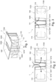
- FIG. 1 a schematic perspective view of an embodiment of the combination device 1 according to the invention is shown.
- the combination device 1 consists of a hob 10 and an extractor device 11.
- the hob 10 consists of a cover plate 100 and cooking modules arranged below the cover plate 100 (not visible).
- a recess 1000 is made in the cover plate 100, which forms the air inlet opening 111.
- the recess 1000 is made in the middle of the width of the cover plate 100 and extends in the depth direction.
- the recess 1000 has a rectangular, elongated shape.
- the length of the recess 1000 i.e. its dimension in the depth direction, corresponds to the length of the cooking modules (not visible).
- the cooking modules are arranged offset to the left and right of the recess 1000.
- the extractor device 11 comprises two fans 110.
- the fans 110 are arranged below the hob 10 in the combination device 1.
- the combination device 1 comprises a device housing 14.
- the fans 110 are arranged in the device housing 14 and are laterally offset from the recess 1000 in the cover plate 100.
- the intake openings (not visible) of the fans 110 each face the recess 1000.
- a filter carrier 120 is inserted into the recess 1000 of the hob 10.
- the upper edge of the filter carrier 120 is formed by an inlet frame 1203. With this inlet frame 1203, the filter carrier 120 rests on the circumference of the recess 1000.
- the lower area of the filter carrier 120 is formed by a collecting channel 1202. Between the inlet frame 1203 and the collecting channel 1202, frames (not visible) extend along the long sides of the filter carrier 120, in which the grease filters (not visible) are held. At the end faces of the filter carrier 120, it is delimited by end walls 1204, which extend between the inlet frame 1203 and the collecting channel 1202.
- An odor filter 1210 is arranged between the filter carrier 120 and the fans 110.
- the odor filters 1210 are aligned vertically and extend from the underside of the hob 10 to the bottom of the appliance housing 14.
- the depth of the odor filters 1210 corresponds to the depth of the recess 1000 or is slightly smaller than the depth of the recess 1000.
- FIG. 2 The arrangement of the filter elements in an embodiment of the combination device 1 according to the invention is shown schematically.
- Two grease filters 1201 are inserted into the recess 1000 of the hob 10.
- the grease filters 1201 are held by a filter carrier 120 on the recess 1000.
- the filter carrier 120 is shown in the Figure 2 only the collecting channel 1202 is indicated schematically.
- the grease filters 1201 are arranged inclined to the vertical.
- the lower edges of the grease filters 1201 lie in the collecting channel 1202.
- the horizontal distance between the grease filters 1201 at their lower edges is smaller than the horizontal distance between the grease filters 1201 at their upper edges in the area of the recess 1000.
- the upper edge of the filter carrier 120 which can be formed by an inlet frame 1203, thus forms the air inlet opening 111 for the extractor device 11.
- An odor filter 1210 is arranged laterally offset from the grease filters 1201.
- the odor filters 1210 are thus located behind the grease filters 1201 in the direction of flow.
- a fan 1100 is arranged after each odor filter 1210 in the direction of flow.
- the fans 110 are each arranged so that their intake opening 1101 faces the odor filter 1210.
- the intake opening 1101 of the respective fans 110 is vertical.
- the rotation axis 1103 of the fan wheel of the blower 110 is perpendicular to the intake opening 1101 and is therefore horizontal.
- the contaminated air sucked in by the blower 110 enters the combination device 1 via the air inlet opening 111. Since two blowers 110 are provided in the combination device 1, the air is divided, with each of the partial air streams first passing through a grease filter 1201. The respective partial air stream then passes through the odor filter 1210 before it reaches the respective blower 110. The air enters the blower 110 via the intake opening 1101. As can be seen from Figure 1 The air is blown out of the blower housing 1100 via the air outlet opening 1102 of the blower housing 1100 and, in the embodiment shown, is guided to the air outlet 13 of the combination device 1 via an air guide channel element 113.
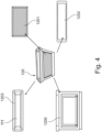
- the filter carrier 120 is shown in a perspective view.
- the filter carrier 120 is a box shape that is open at the top and whose side walls are inclined.
- the upper area of the filter carrier 120 is formed by the inlet frame 1203, which is shown in plan view at the top left.
- the frames 1200 adjoin the inlet frame 1203 at the bottom on the two long sides. These are shown in the Figure 4 shown at the bottom left.
- the lower part of the filter carrier 120 is formed by the collecting channel 1202, which Figure 4 shown below right.
- a grease filter 1201 is inserted into the frame 1200, which is Figure 4 shown schematically as a filter cassette at the top right.
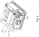
- FIG 5 is a schematic plan view of an air inlet housing 112.
- the air inlet housing 112 has an inlet nozzle which has a width and depth which is slightly larger than the recess 1000 of the hob 10. Below the inlet nozzle, the air inlet housing 112 widens out to the sides. In this area, the air inlet housing 112 forms vertically standing holder frames 1211. On the side of the respective holder frame 1211 facing away from the inlet nozzle, the air inlet housing 112 tapers and has the shape and size of the intake opening 1101 of the fan 110 at its outer end. In the Figure 5 only a part of the blower housing 1100 is shown schematically.
- the air inlet housing 112 consists of a base body 1121 and two side bodies 1122.
- the base body 1121 has an elongated box shape whose depth is greater than its width.
- the height of the base body 1121 is greater than the height of the side bodies 1122.
- the holding frames 1211 each have a rectangular cross-section whose depth is less than the depth of the inlet nozzle.
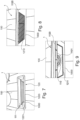
- FIG 7 a perspective view of the combination device 1 is shown in the area of the recess 1000.
- a filter carrier 120 is inserted into the recess 1000.
- the upper edge of the inlet frame 1203 lies in the recess 1000 in the embodiment shown.
- the inlet frame 1203 thus forms the air inlet opening 111 for the extractor device 11.
- Grease filters 1201 extend downwards from the inlet frame 1203.
- the combination device is Figure 7 without filter carrier 120. From this Figure 8 It can be seen that after removing the filter carrier 120, the odor filters 1210 downstream in the flow direction are accessible to the user. In the Figure 8 Only one odor filter 1210 is visible, another odor filter 1210 is arranged on the opposite long side of the recess 1000.
- the inlet nozzle 1120 of the air inlet housing 112 and the end walls 1204 of the air inlet housing 112 are visible.
- the odor filter 1210 is accommodated in the holder frame 1211, which is formed by a part of the air inlet housing 112, in particular the side body 1122.
- the fan 110 in particular the intake opening 1101 of the fan 110, is located laterally behind the holder frame 1211.
- the present invention is not limited to the embodiments shown. In particular, other shapes or arrangements of fans can be used.
- the holder of the odor filter can also be designed in a different way from the ones shown. Designs can be made on separate holder frames, which do not necessarily have to form part of an air inlet housing.
- the essence of the invention is that the odor filter is arranged between the grease filter and the fan, in particular the fan motor.
- the combination device according to the invention has a compact structure, since the individual components of the extractor device, in particular the grease filter, the odor filter and the fan, can be arranged in close proximity to one another.
- the odor filter is arranged in front of the fan in the direction of flow, it can also serve as noise insulation.
- the odor filter is arranged in the area of the air inlet opening for the extractor device and in particular near the recess in the hob, it can be removed directly upwards by the user. In addition, the user can gain an insight into the odor filter and thus visually check whether the odor filter needs to be replaced.
- the air flow that flows from the grease filter to the fan of the combination device is subject to no or only a slight change in direction.
- the odor filter which is arranged after the grease filter in the direction of flow, serves to evenly distribute the incoming air to the grease filter and thus increases the filter efficiency.
Landscapes
- Engineering & Computer Science (AREA)
- Chemical & Material Sciences (AREA)
- Combustion & Propulsion (AREA)
- Mechanical Engineering (AREA)
- General Engineering & Computer Science (AREA)
- Filtering Of Dispersed Particles In Gases (AREA)
- Disinfection, Sterilisation Or Deodorisation Of Air (AREA)
Description
- Die vorliegende Erfindung betrifft ein Kombinationsgerät mit Dunstabzugsvorrichtung und Kochfeld.
- Bei Kochvorgängen entstehen in der Regel Dünste und Wrasen. Es sind Dunstabzugsvorrichtungen bekannt, mittels derer die Dünste und Wrasen abgesaugt und gereinigt werden können. Hierzu sind beispielsweise Kombinationsgeräte bekannt, bei denen eine Dunstabzugsvorrichtung unterhalb des Kochfeldes angeordnet ist.
- In der der
KR 2006 0087209 A - In der
GB 1 232 982 A - In der
US 2010/0163549 A1 ist ein Induktionskochfeld mit einem Wärmemanagementsystem beschrieben. Gemäß einer Ausführungsform ist in diesem Kochfeld ist in der Mitte des Kochfeldes eine Lüfteröffnung vorgesehen. Unterhalb der Lüfteröffnung ist ein Raum vorgesehen, an dessen Seitenwand ein Lüfter angeordnet ist. In dem Raum ist ein Filterelement schräg angeordnet. Das Filterelement wird zum Ausfiltern von Verunreinigungen verwendet und kann ein Aktivkohlefilter oder ein Metallgitter aufweisen. - In der
DE 10 2008 033 792 B4 sind eine Dunstabzugsvorrichtung und ein Umluftmodul beschrieben. - Ein weiteres Kombinationsgerät ist beispielsweise in der
DE 20 2013 005 303 U1 beschrieben. Bei diesem Kombinationsgerät ist unterhalb des Kochfeldes ein Lüftergehäuse für zwei oder mehrere Radiallüfter angeordnet, die Luft aus der darunter liegenden Kochdunstansaugkammer absaugen. An das Lüftergehäuse schließt sich eine Ausblaskammer an. Von dort gelangt die Luft zu einem Geruchsfilter, der sich an der Rückseite des Kombinationsgerätes befindet. - Dieses Kombinationsgerät weist den Nachteil auf, dass der Geruchsfilter für den Benutzer des Kombinationsgerätes nur schwer zugänglich ist.
- Daher ist es Aufgabe der Erfindung eine Lösung zu schaffen, bei der zum einen Dünste und Wrasen zuverlässig gereinigt und insbesondere von Geruchsstoffen befreit werden können und bei der zum anderen die Benutzerfreundlichkeit gesteigert ist.
- Die Aufgabe wird daher erfindungsgemäß gelöst durch ein Kombinationsgerät mit den Merkmalen des Anspruchs 1.
- Richtungsangaben, wie beispielsweise oben und unten sowie vorne und hinten beziehen sich, soweit nicht anders angegeben, auf das Kombinationsgerät und dessen Bestandteile in einem eingebauten Zustand, bei dem das Kochfeld in der Horizontalen liegt. Als Vorderseite wird die Seite bezeichnet, die dem Benutzer zugewandt ist. Die Rückseite ist die Seite, die in der Regel einer Montagewand zugewandt ist. Zudem ist die Rückseite des Kombinationsgerätes vorzugsweise die Seite, über die gereinigte Luft aus dem Kombinationsgerät ausgegeben wird. Die Abmessung in der Richtung zwischen Vorderseite und Rückseite wird als Tiefe bezeichnet. Die dazu senkrechte Abmessung in der Horizontalen wird als Breite bezeichnet. Die Abmessung in der Vertikalen wird als Höhe bezeichnet.
- Als Kombinationsgerät wird ein Haushaltsgerät bezeichnet, bei dem ein Kochfeld und eine Dunstabzugsvorrichtung miteinander kombiniert sind. Insbesondere wird als Kombinationsgerät ein Haushaltsgerät bezeichnet, das als eine Montageeinheit in eine Küche eingebaut werden kann. Vorzugsweise werden die beiden Komponenten des Kombinationsgerätes, d.h. das Kochfeld und die Dunstabzugsvorrichtung, durch eine gemeinsame Stromversorgung beispielsweise ein gemeinsames Netzkabel versorgt. Zudem kann die Steuerung der beiden Komponenten durch eine gemeinsame Steuervorrichtung erfolgen, bei der Steuervorrichtungen für die beiden Komponenten kombiniert sind. Beispielsweise können die beiden Komponenten auch durch eine gemeinsame Bedieneinheit bedient werden.
- Das Kombinationsgerät umfasst ein Kochfeld, eine Dunstabzugsvorrichtung sowie eine Lufteinlassöffnung für die Dunstabzugsvorrichtung. Das Kochfeld weist mindestens ein Kochmodul auf. Zudem umfasst das Kochfeld vorzugsweise eine Deckplatte, an der das oder die Kochmodule von unten angeordnet sind. Die Deckplatte kann beispielsweise aus Glaskeramik bestehen. Durch jedes der Kochmodule wird mindestens eine Kochzone gebildet, das heißt ein Bereich, auf dem auf dem Kochfeld Gargut erwärmt werden kann. Das Kochmodul kann ein elektrisches Heizmodul mit einer Heizspule darstellen. Das Kochmodul stellt aber vorzugsweise ein Induktionsmodul dar und wird auch als Induktor bezeichnet. Das Induktionsmodul umfasst vorzugsweise zumindest eine Induktionsspule.
- Das Kombinationsgerät umfasst weiterhin eine Dunstabzugsvorrichtung. Als Dunstabzugsvorrichtung wird eine Vorrichtung bezeichnet, mit der Luft, insbesondere verunreinigte Luft, beispielsweise in Form von Dünsten und Wrasen von dem Raum oberhalb des Kochfeldes nach unten gesaugt werden kann. Die Luft wird in der Dunstabzugsvorrichtung gereinigt und als gereinigte Luft bzw. Reinluft aus der Dunstabzugsvorrichtung und dem Kombinationsgerät abgegeben. Die Dunstabzugsvorrichtung umfasst daher zumindest ein Gebläse. Als Gebläse wird hierbei eine Einheit bestehend aus einem Lüfter, insbesondere Lüfterrad, und einem den Lüfter umgebenden Gebläsegehäuse verstanden. Der Lüfter stellt vorzugsweise einen Radiallüfter, insbesondere einen Radiallüfter mit vorwärtsgekrümmten Schaufeln, dar und das Gebläsegehäuse stellt vorzugsweise ein Spiralgehäuse dar, das auch als Schneckengehäuse bezeichnet werden kann. Das Gebläse weist zumindest eine Ansaugöffnung auf. Die Ansaugöffnung ist in dem Gebläsegehäuse ausgebildet. Erfindungsgemäß kann das Gebläse eine oder zwei Ansaugöffnungen aufweisen. Ein Gebläse mit einer Ansaugöffnung wird auch als einflutiges Gebläse bezeichnet und ein Gebläse mit zwei Ansaugöffnungen als doppelflutiges Gebläse bezeichnet. Vorzugsweise wird erfindungsgemäß zumindest ein und besonders bevorzugt zwei einflutige Gebläse verwendet. Die Ansaugöffnung der Gebläse liegt vorzugsweise in der Vertikalen.
- Das Kombinationsgerät weist weiterhin zumindest eine Lufteinlassöffnung für die Dunstabzugsvorrichtung auf. Als Lufteinlassöffnung wird die Öffnung bezeichnet, über die Luft von oberhalb des Kochfeldes in das Kombinationsgerät eintritt. Die Lufteinlassöffnung für die Dunstabzugsvorrichtung wird im Folgenden auch als Lufteinlassöffnung der Dunstabzugsvorrichtung bezeichnet. Die Lufteinlassöffnung ist in dem Kochfeld angeordnet. Insbesondere ist die Lufteinlassöffnung in einer Aussparung in dem Kochfeld, insbesondere einer Aussparung in der Deckplatte des Kochfeldes angeordnet. Die Lufteinlassöffnung kann in der Aussparung des Kochfeldes liegen oder durch diese gebildet sein. Das oder die Kochmodule liegen zu der Aussparung des Kochfeldes versetzt. Die Aussparung in dem Kochfeld stellt vorzugsweise eine längliche Aussparung dar, die besonders bevorzugt einen rechteckigen Querschnitt aufweist. Vorzugsweise erstreckt sich die Aussparung in der Tiefenrichtung des Kochfeldes und ist besonders bevorzugt in der Mitte der Breite des Kochfeldes angeordnet.
- Die Dunstabzugsvorrichtung ist zumindest teilweise unterhalb des Kochfeldes angeordnet. Insbesondere sind zumindest das oder die Gebläse der Dunstabzugsvorrichtung zu dem Kochfeld nach unten versetzt angeordnet und befinden sich unterhalb des mindestens einen Kochmoduls des Kochfeldes.
- Das Kombinationsgerät weist zumindest einen Fettfilter und zumindest einen Geruchsfilter auf, die zwischen der Lufteinlassöffnung und dem mindestens einen Gebläse angeordnet sind.
- Der Fettfilter kann beispielsweise eine Filterkassette sein, bei der Streckmetall als Filtermaterial dient. Hierbei können mehrere Lagen Streckmetall in dem Fettfilter vorgesehen sein.
- Als zwischen der Lufteinlassöffnung und dem Gebläse angeordnet werden Geruchsfilter und Fettfilter bezeichnet, die in Strömungsrichtung zwischen der Lufteinlassöffnung und einer Ansaugöffnung des Gebläses liegen. Als Geruchsfilter kann beispielsweise ein Aktivkohlefilter verwendet werden. Der Geruchsfilter kann die Form einer Platte, Matte oder eines Formkörpers haben. Der Geruchsfilter kann vorzugsweise aus einer plissierten Matte von Filtermaterial bestehen. Besonders bevorzugt ist der Geruchsfilter ein flächiger Geruchsfilter.
- Indem der Geruchsfilter zwischen der Lufteinlassöffnung der Dunstabzugsvorrichtung und dem Gebläse angeordnet ist, können Geräusche, die durch den Betrieb des Gebläses entstehen, durch den Geruchsfilter gedämpft werden. Damit wird der Geräuschpegel, der für den Benutzer des Kombinationsgerätes wahrnehmbar ist, verringert.
- Erfindungsgemäß liegt der mindestens eine Geruchsfilter in Strömungsrichtung hinter dem mindestens einen Fettfilter. Auf diese Weise kann anströmende Luft zunächst an dem Fettfilter von flüssigen Verunreinigungen, insbesondere Fettpartikel, befreit werden. Die so vorgereinigte Luft gelangt dann zu dem Geruchsfilter, wo Geruchspartikel aus der Luft ausgefiltert werden. Der Geruchsfilter muss einen hohen Luftwiderstand aufweisen, um die Geruchspartikel in diesem herauszufiltern. Durch diesen hohen Luftwiderstand verteilt sich die angesaugte Luft vor dem Fettfilter über dessen gesamte Fläche. Somit kann eine zuverlässige Reinigung der verunreinigten Luft gewährleistet werden. Zudem müssen Fettfilter häufiger gereinigt werden. Indem der Geruchsfilter in Strömungsrichtung nach dem Fettfilter liegt, ist der oder sind die Fettfilter für den Benutzer des Kombinationsgerätes auf einfache Weise zugänglich und werden insbesondere nicht durch den Geruchsfilter verdeckt. Nach der Entnahme des Fettfilters ist für den Benutzer auch der Geruchsfilter sichtbar. Auf diese Weise kann der Benutzer auf einfache Weise entscheiden, ob ein Austausch oder eine Reinigung des Geruchsfilters notwendig ist. Der Geruchsfilter liegt erfindungsgemäß benachbart zu dem Fettfilter. Die Filter können dabei aneinander anliegen oder in geringem Abstand zueinander angeordnet sein.
- Vorzugsweise ist der mindestens eine Geruchsfilter lösbar in dem Kombinationsgerät gehalten. Hierdurch wird ein Austausch oder eine Entnahme des Geruchsfilters zu Reinigungszwecken ermöglicht. Der Geruchsfilter liegt vorzugsweise als separater Filter zu dem Fettfilter vor. Somit kann der Benutzer je nach Bedarf den Fettfilter und gegebenenfalls zusätzlich den Geruchsfilter aus dem Kombinationsgerät entnehmen.
- Der mindestens eine Geruchsfilter wird vorzugsweise in einem Filterhalter gehalten. Der Filterhalter kann beispielsweise einen Rahmen oder Gestell sein, dass im Inneren des Kombinationsgerätes angeordnet ist. Der Filterhalter kann an der Unterseite des Kochfeldes befestigt sein. Der Filterhalter kann allerdings auch durch ein Gerätegehäuse des Kombinationsgerätes, in dem die Dunstabzugsvorrichtung aufgenommen ist, gebildet sein. Hierbei kann der Geruchsfilter beispielsweise auf den Boden des Gerätegehäuses oder einer an dem Boden vorgesehenen Haltevorrichtung aufgesetzt werden.
- Gemäß einer bevorzugten Ausführungsform weist das Kombinationsgerät ein Lufteinlassgehäuse auf. Das Lufteinlassgehäuse erstreckt sich von der Lufteinlassöffnung für die Dunstabzugsvorrichtung zu der mindestens einen Ansaugöffnung des Gebläses. Das Lufteinlassgehäuse dient zur Luftführung in dem Kombinationsgerät. Insbesondere wird durch das Lufteinlassgehäuse ein Strömungsraum gebildet, indem die Luftströmung von der Lufteinlassöffnung zu der Ansaugöffnung geleitet wird. Vorzugsweise ist der Filterhalter für den Geruchsfilter Teil des Lufteinlassgehäuses. Insbesondere kann der Filterhalter für den Geruchsfilter durch eine Vertiefung oder einen verjüngten Bereich des Lufteinlassgehäuses gebildet werden. Diese Ausführungsform, bei der der Geruchsfilter an dem Lufteinlassgehäuse gehalten wird, ist vorteilhaft, da hierdurch die benötigte Anzahl an Bauteilen verringert werden kann. Der Teil des Lufteinlassgehäuses, der als Filterhalter für den Geruchsfilter dient, ist in dem Lufteinlassgehäuse unlösbar ausgebildet. Da Geruchsfilter in der Regel eine Stabilität aufweisen, die deren Handhabung erlaubt, kann der oder können die Geruchsfilter aus der Filterhalterung dem Lufteinlassgehäuse entnommen werden, ohne dass die Filterhalterung ebenfalls entnommen werden muss.
- Gemäß einer bevorzugten Ausführungsform entspricht die Fläche des Geruchsfilters zumindest der Fläche des Fettfilters. Besonders bevorzugt weist der Geruchsfilter eine Abmessung auf, die geringer ist, als die Abmessungen der Aussparung in dem Kochfeld. Insbesondere weist der Geruchsfilter eine Länge auf, die geringer ist als die Länge der Aussparung in dem Kochfeld. Zudem ist auch die Dicke bzw. Stärke des Geruchsfilters geringer als die Breite der Aussparung in dem Kochfeld. Auf diese Weise kann der Geruchsfilter durch die Aussparung des Kochfeldes nach oben entnommen werden. Bei der Ausführungsform, bei der die Fläche des Geruchsfilters der Fläche des Fettfilters entspricht, kann zum einen gewährleistet werden, dass die gesamte Luft, die durch den Fettfilter hindurch tritt, zu dem Geruchsfilter gelangt. Zudem kann bei dieser Ausführungsform gesamte Fläche des Geruchsfilters zum Herausfiltern von Geruchsstoffen genutzt werden.
- In dem Kombinationsgerät vorzugsweise ein Fettfilter und ein Geruchsfilter benachbart zueinander. Der Geruchsfilter ist vorzugsweise vertikal in dem Kombinationsgerät angeordnet. Der Geruchsfilter kann dabei die gesamte Höhe des Inneren des Kombinationsgerätes abdecken.
- Erfindungsgemäß liegt der Geruchsfilter parallel zu dem Fettfilter. Hierdurch kann ein gleichmäßiges Anströmen des Geruchsfilters von Luft, die durch den Fettfilter hindurchgetreten ist, gewährleistet werden.
- Erfindungsgemäß wird der mindestens eine Fettfilter in einem Filterträger gehalten. Der Filterträger ist in dem Kombinationsgerät lösbar befestigt und erstreckt sich von der Lufteinlassöffnung für die Dunstabzugsvorrichtung nach unten. Vorzugsweise werden mehrere, insbesondere zwei Fettfilter in dem Filterträger gehalten. Indem einen Filterträger vorgesehen ist, können mehrere Fettfilter gleichzeitig aus dem Kombinationsgerät entnommen und in dieses eingebracht werden. Hierzu kann der Filterträger in die Aussparung des Kochfeldes eingebracht werden. Von der Aussparung und damit der Lufteinlassöffnung erstreckt sich der Filterträger nach unten. Der Filterträger weist vorzugsweise zumindest einen Rahmen auf in dem ein Fettfilter gehalten werden kann. Vorzugsweise sind zwei Rahmen vorgesehen, die einander gegenüberliegen. Die Rahmen können vorzugsweise an einem Einlassrahmen befestigt sein, der den oberen Bereich des Filterträgers bildet und zur Auflage auf dem Umfang der Aussparung des Kochfeldes dient. Der Filterträger ist somit vorzugsweise ein Gerüst, das nach oben offen ist, und nach unten verschlossen ist. Zwei Seitenwände den Filterträgers können durch die Rahmen zur Aufnahme der Fettfilter gebildet sein. Diese Seiten sind vorzugsweise Längsseiten des Filterträgers. Die kürzeren Stirnseiten des Filterträgers sind vorzugsweise aus luftundurchlässigem Material hergestellt.
- Gemäß einer Ausführungsform umfasst der Filterträger eine Auffangrinne, die mit mindestens einem Rahmen des Filterträgers verbunden ist. Insbesondere bildet die Auffangrinne den Boden des Filterträgers. Der oder die Rahmen des Filterträgers sind dabei so angeordnet, dass deren unterer Rand an die Auffangrinne angrenzt oder in dieser aufgenommen ist. Hierdurch können Verunreinigungen, die an dem Fettfilter abgeschieden werden und an diesem herunterlaufen, gesammelt werden. Besonders bevorzugt ist die Auffangrinne von dem mindestens einen Filterträger, insbesondere von den Rahmen des Filterträgers, lösbar ausgestaltet. Hierdurch kann die Auffangrinne bei Bedarf entleert werden.
- Das oder die Filterelemente können in dem Filterträger vertikal angeordnet sein. Bei dieser Ausführungsform weist der Filterträger eine nach oben offene Kastenform auf, wobei mindestens eine der Seitenwände und vorzugsweise die beiden Längsseitenwände durch Rahmen für die Fettfilter gebildet sind. Gemäß einer Ausführungsform sind die Fettfilter aber vorzugsweise zu der Vertikalen geneigt in dem Filterträger gehalten. Bei dieser Ausführungsform ist der bzw. sind die Rahmen des Filterträgers ebenfalls zu der Vertikalen geneigt angeordnet. Der Filterträger kann bei dieser Ausführungsform einen V-förmigen Querschnitt bilden. Durch die geneigte Ausrichtung des Fettfilters kann ein Heruntertropfen von Verunreinigungen verhindert werden. Zudem wird durch eine geneigte Ausrichtung der Fettfilter der Raum, der durch diese im Inneren des Kombinationsgerätes in Anspruch genommen wird, verringert.
- Erfindungsgemäß ist die Aussparung in der Mitte der Breite des Kochfeldes angeordnet und erstreckt sich in der Tiefenrichtung des Kochfeldes. In die Aussparung ist ein Filterträger eingebracht, in dem die Fettfilter in der Vertikalen gehalten sind oder zu der Vertikalen geneigt angeordnet sind. Die Fettfilter erstrecken sich somit von der Aussparung nach unten. In Strömungsrichtung nach dem jeweiligen Fettfilter und parallel zu dem Fettfilter ist jeweils ein Geruchsfilter angeordnet. In Strömungsrichtung nach den Geruchsfilter jeweils ein Gebläse angeordnet. Das Gebläse ist vorzugsweise so angeordnet, dass die Ansaugöffnung des Gebläses dem Geruchsfilter zugewandt ist. Erfindungsgemäß liegen die Flächenmitten des Fettfilters, des Geruchsfilters und der Ansaugöffnung auf einer horizontalen Ebene. Besonders bevorzugt sind in dem Kombinationsgerät zwei Fettfilter, die in einem Filterträger gehalten sind, zwei Geruchsfilter und zwei Gebläse vorgesehen. Wird in dem Kombinationsgerät ein Lufteinlassgehäuse verwendet, so weist dieses vorzugsweise einen Grundkörper sowie seitlich daran anschließende Seitenkörper auf. An der Oberseite des Grundkörpers ist vorzugsweise ein Einlassstutzen vorgesehen, dessen Fläche der Fläche der Aussparung in dem Kochfeld entspricht. Der Grundkörper weißt vorzugsweise eine Kastenform auf, deren Höhe größer ist als deren Breite. Die Tiefe des Grundkörpers vorzugsweise größer als die Tiefe der Aussparung des Kochfeldes. Nach oben ist der Grundkörper zu dem Einlassstutzen offen. In dem Grundkörper des Lufteinlassgehäuses wird der Filterträger für die Fettfilter aufgenommen. In den Seitenwänden des Grundkörpers sind Öffnungen vorgesehen, über die der Grundkörper in die Seitenkörper übergeht. Die Seitenkörper weisen vorzugsweise eine Rahmenform auf und dienen sonders bevorzugt als Halterrahmen für die Geruchsfilter. An der Seite der Seitenkörper, die den Grundkörper abgewandt ist, weißt jeder der Seitenkörper vorzugsweise eine trichterförmigen Seitenwand auf, die in einer runden Öffnung endet. Die Größe der runden Öffnung in der trichterförmigen Seitenwand entspricht der Größe der Ansaugöffnung des Gebläses. Es ist allerdings auch möglich, dass die Seitenwand eine ebene, vertikalen Wand darstellt, in der die entsprechende runde Öffnung eingebracht ist. Ist ein Gerätegehäuses vorgesehen, so weist dieses vorzugsweise eine nach offene Kastenform auf, die durch das Kochfeldes verschlossen wird.
- Die vorliegende Erfindung wird im Folgenden erneut unter Bezugnahme auf die beiliegenden Figuren genauer erläutert. Es zeigen:
-
Figur 1 : eine schematische Perspektivansicht einer Ausführungsform des erfindungsgemäßen Kombinationsgerätes; -
Figur 2 : eine schematische Prinzipdarstellung der Anordnung der Fettfilter und Geruchsfilter einer Ausführungsform des erfindungsgemäßen Kombinationsgerätes; -
Figur 3 : eine schematische Prinzipdarstellung der Entnahme der Fettfilter und Geruchsfilter der Ausführungsform des Kombinationsgerätes nachFigur 2 ; -
Figur 4 : eine schematische Detaildarstellung der Bestandteile einer Ausführungsform eines Filterträgers; -
Figur 5 : eine schematische Draufsicht auf ein Lufteinlassgehäuse; -
Figur 6 : eine schematische perspektivische Unteransicht einer Ausführungsform des Lufteinlassgehäuses; -
Figur 7 : eine schematische Perspektivansicht des Kombinationsgerätes im Bereich der Lufteinlassöffnung; -
Figur 8 : eine schematische Perspektivansicht des Kombinationsgerätes im Bereich der Lufteinlassöffnung ohne Filterträger; und -
Figur 9 : eine schematische Perspektivansicht des Kombinationsgerätes im Bereich der Lufteinlassöffnung ohne Filterträger und ohne Geruchsfilter. - In
Figur 1 ist eine schematische Perspektivansicht einer Ausführungsform des erfindungsgemäßen Kombinationsgerätes 1 gezeigt. Das Kombinationsgerät 1 besteht aus einem Kochfeld 10 und einer Dunstabzugsvorrichtung 11. - Das Kochfeld 10 besteht aus einer Deckplatte 100 und unterhalb der Deckplatte 100 angeordneten Kochmodulen (nicht sichtbar). In der Deckplatte 100 ist eine Aussparung 1000 eingebracht, die die Lufteinlassöffnung 111 bildet. In der gezeigten Ausführungsform ist die Aussparung 1000 in der Mitte der Breite der Deckplatte 100 eingebracht und erstreckt sich in Tiefenrichtung. Die Aussparung 1000 weist in der dargestellten Ausführungsform eine rechteckige, längliche Form auf. Die Länge der Aussparung 1000, d.h. deren Abmessung im Tiefenrichtung, entspricht der Länge der Kochmodule (nicht sichtbar). Die Kochmodule sind links und rechts zu der Aussparung 1000 versetzt angeordnet.
- Die Dunstabzugsvorrichtung 11 umfasst in der dargestellten Ausführungsform zwei Gebläse 110. Die Gebläse 110 sind unterhalb des Kochfeldes 10 in dem Kombinationsgerät 1 angeordnet. In der dargestellten Ausführungsform umfasst das Kombinationsgerät 1 ein Gerätegehäuse 14. Die Gebläse 110 sind in dem Gerätegehäuse 14 angeordnet und zu der Aussparung 1000 in der Deckplatte 100 seitlich versetzt angeordnet. Die Ansaugöffnungen (nicht sichtbar) der Gebläse 110 sind jeweils der Aussparung 1000 zugewandt.
- In die Aussparung 1000 des Kochfeldes 10 ist ein Filterträger 120 eingebracht. Der obere Rand des Filterträgers 120 wird durch einen Einlassrahmen 1203 gebildet. Mit diesem Einlassrahmen 1203 liegt der Filterträger 120 auf dem Umfang der Aussparung 1000 auf. Der untere Bereich des Filterträgers 120 wird durch eine Auffangrinne 1202 gebildet. Zwischen dem Einlassrahmen 1203 und der Auffangrinne 1202 erstrecken sich an den Längsseiten des Filterträgers 120 Rahmen (nicht sichtbar), in denen die Fettfilter (nicht sichtbar) gehalten sind. An den Stirnseiten des Filterträgers 120 ist dieser durch Stirnwände 1204 begrenzt, die sich zwischen dem Einlassrahmen 1203 und der Auffangrinne 1202 erstrecken.
- Zwischen dem Filterträger 120 und den Gebläsen 110 ist jeweils ein Geruchsfilter 1210 angeordnet. Die Geruchsfilter 1210 sind in der dargestellten Ausführungsform vertikal ausgerichtet und erstrecken sich von der Unterseite des Kochfeldes 10 zu dem Boden des Gerätegehäuses 14. Die Tiefe der Geruchsfilter 1210 entspricht der Tiefe der Aussparung 1000 bzw. ist geringfügig kleiner als die Tiefe der Aussparung 1000.
- In der
Figur 2 ist die Anordnung der Filterelemente in einer Ausführungsform des erfindungsgemäßen Kombinationsgerätes 1 schematisch dargestellt. In die Aussparung 1000 des Kochfeldes 10 sind zwei Fettfilter 1201 eingebracht. Die Fettfilter 1201 werden von einem Filterträger 120 an der Aussparung 1000 gehalten. Von dem Filterträger 120 ist in derFigur 2 nur die Auffangrinne 1202 schematisch angedeutet. Die Fettfilter 1201 sind in der gezeigten Ausführungsform zu der Vertikalen geneigt angeordnet. Die unteren Ränder der Fettfilter 1201 liegen in der Auffangrinne 1202. Der horizontale Abstand zwischen den Fettfiltern 1201 an deren unteren Rändern ist geringer als der horizontale Abstand zwischen den Fettfiltern 1201 an deren oberen Rändern im Bereich der Aussparung 1000. Der obere Rand des Filterträgers 120, der durch einen Einlassrahmen 1203 gebildet sein kann, bildet damit die Lufteinlassöffnung 111 für die Dunstabzugsvorrichtung 11. - Zu den Fettfiltern 1201 seitlich versetzt liegt jeweils ein Geruchsfilter 1210. Die Geruchsfilter 1210 liegen somit in Strömungsrichtung hinter den Fettfiltern 1201. In Strömungsrichtung ist nach jedem Geruchsfilter 1210 ein Gebläse 1100 angeordnet. Die Gebläse 110 sind jeweils so angeordnet, dass deren Ansaugöffnung 1101 dem Geruchsfilter 1210 zugewandt ist. Die Ansaugöffnung 1101 der jeweiligen Gebläse 110 liegt dabei in der Vertikalen. Die Drehachse 1103 des Lüfterrades des Gebläses 110 steht senkrecht zu der Ansaugöffnung 1101 liegt damit in der Horizontalen.
- Wie in
Figur 2 durch die Pfeile angedeutet, tritt die durch die Gebläse 110 eingesaugte, verunreinigte Luft über die Lufteinlassöffnung 111 in das Kombinationsgerät 1 ein. Da zwei Gebläse 110 in dem Kombinationsgerät 1 vorgesehen sind, teils sich die Luft auf, wobei jeder der Teilluftströme zunächst durch einen Fettfilter 1201 hindurchtritt. Anschließend passiert der jeweilige Teilluftstrom den Geruchsfilter 1210, bevor dieser das jeweilige Gebläse 110 erreicht die Luft tritt über die Ansaugöffnung 1101 des Gebläses 110 in dieses eintritt. Wie sich ausFigur 1 ergibt wird die Luft aus dem Gebläsegehäuse 1100 über die Luftauslassöffnung 1102 des Gebläsegehäuses 1100 ausgeblasen und in der dargestellten Ausführungsform über ein Luftführungskanalelement 113 zu dem Luftauslass 13 des Kombinationsgerätes 1 geführt. - In
Figur 3 ist schematisch die Entnahme der Fettfilter 1201 und Geruchsfilter 1210 gezeigt. Zunächst wird der Filterträger 120 nach oben aus der Aussparung 1000 des Kochfeldes 10 herausgenommen. Hierdurch wird der Zugriff auf die Geruchsfilter 1210 für den Benutzer möglich. Die Geruchsfilter 1210 werden durch Verschwenken in Richtung der Aussparung 1000 unter die Aussparung 1000 gebracht und können über diese nach oben entnommen werden. - In der
Figur 4 sind die Teile des Filterträgers 120 genauer gezeigt. In der Mitte derFigur 4 ist der Filterträger 120 in einer perspektivischen Ansicht gezeigt. Der Filterträger 120 stellt in der dargestellten Ausführungsform eine nach oben offene Kastenform dar, deren Seitenwände geneigt sind. Der obere Bereich des Filterträgers 120 wird durch den Einlassrahmen 1203 gebildet, der oben links in Draufsicht gezeigt ist. An den Einlassrahmen 1203 schließen sich nach unten an den beiden Längsseiten die Rahmen 1200 an. Diese sind in derFigur 4 unten links gezeigt. Den unteren Bereich des Filterträgers 120 bildet die Auffangrinne 1202, die inFigur 4 unten rechts gezeigt ist. In den Rahmen 1200 ist jeweils einen Fettfilter 1201 eingesetzt, der inFigur 4 oben rechts schematisch als Filterkassette gezeigt ist. - In
Figur 5 ist eine schematische Draufsicht auf ein Lufteinlassgehäuse 112 gezeigt. Das Lufteinlassgehäuse 112 weist einen Einlassstutzen auf, der eine Breite und Tiefe aufweist, die geringfügig größer ist, als die Aussparung 1000 des Kochfeldes 10. Unterhalb des Einlassstutzen erweitert sich das Lufteinlassgehäuse 112 zu den Seiten. In diesem Bereich bildet das Lufteinlassgehäuse 112 vertikal stehende Halterrahmen 1211. An der dem Einlassstutzen abgewandten Seite des jeweiligen Halterrahmens 1211 verjüngt sich das Lufteinlassgehäuse 112 und weist an dessen äußeren Ende die Form und Größe der Ansaugöffnung 1101 des Gebläses 110 auf. In derFigur 5 ist nur ein Teil des Gebläsegehäuses 1100 schematisch gezeigt. Wie sich ausFigur 6 ergibt, besteht das Lufteinlassgehäuse 112 aus einem Grundkörper 1121 zwei Seitenkörpern 1122. Der Grundkörper 1121 weißt eine längliche Kastenform auf, deren Tiefe größer ist, als deren Breite. Die Höhe des Grundkörpers 1121 ist größer als die Höhe der Seitenkörper 1122. - Die Halterahmen 1211 weisen jeweils einen rechteckigen Querschnitt auf, dessen Tiefe geringer ist, als die Tiefe des Einlassstutzens.
- In der
Figur 7 ist eine perspektivische Ansicht des Kombinationsgerätes 1 im Bereich der Aussparung 1000 gezeigt. In die Aussparung 1000 ist ein Filterträger 120 eingebracht. Der obere Rand des Einlassrahmens 1203 liegt in der gezeigten Ausführungsform in der Aussparung 1000. Der Einlassrahmen 1203 bildet damit die Lufteinlassöffnung 111 für die Dunstabzugsvorrichtung 11. Von dem Einlassrahmen 1203 erstrecken sich Fettfilter 1201 nach unten. In derFigur 8 ist das Kombinationsgerät nachFigur 7 ohne Filterträger 120 gezeigt. Aus dieserFigur 8 ist ersichtlich, dass nach der Entnahme des Filterträgers 120 die in Strömungsrichtung nachgeschalteten Geruchsfilter 1210 für den Benutzer zugänglich sind. In derFigur 8 ist nur ein Geruchsfilter 1210 sichtbar, ein weiterer Geruchsfilter 1210 ist auf der gegenüberliegenden Längsseite der Aussparung 1000 angeordnet. In derFigur 8 ist der Einlassstutzen 1120 des Lufteinlassgehäuse 112 sowie die Stirnwände 1204 des Lufteinlassgehäuses 112 sichtbar. Der Geruchsfilter 1210 ist in dem Halterrahmen 1211, der durch ein Teil des Lufteinlassgehäuses 112, insbesondere den Seitenkörper 1122 gebildet ist, aufgenommen. Wie sich ausFigur 9 entnehmen lässt, in der der Geruchsfilter 1210 nicht gezeigt ist, liegt das Gebläse 110 insbesondere die Ansaugöffnung 1101 des Gebläses 110 seitlich hinter dem Halterrahmen 1211. - Die vorliegende Erfindung ist nicht auf die dargestellten Ausführungsformen beschränkt. Insbesondere können andere Formen oder Anordnungen von Gebläsen verwendet werden. Auch die Halterung des Geruchsfilters kann in Abweichung von den gezeigten Ausführungsformen an separaten Halterrahmen erfolgen, die nicht zwangsweise Teil eines Lufteinlassgehäuses bilden müssen.
- Kern der Erfindung ist, dass der Geruchsfilter zwischen dem Fettfilter und dem Gebläse, insbesondere dem Gebläsemotor angeordnet ist.
- Die vorliegende Erfindung weist eine Reihe von Vorteilen auf. Zum einen besitzt das erfindungsgemäße Kombinationsgerät einen kompakten Aufbau, da die einzelnen Komponenten der Dunstabzugsvorrichtung, insbesondere der Fettfilter, der Geruchsfilter und das Gebläse in unmittelbarer Nähe zueinander angeordnet sein können. Indem der Geruchsfilter in Strömungsrichtung vor dem Gebläse angeordnet ist, kann dieser darüber hinaus als Geräuschdämmung dienen. Da der Geruchsfilter im Bereich der Lufteinlassöffnung für die Dunstabzugsvorrichtung und insbesondere in der Nähe der Aussparung des Kochfeldes angeordnet ist, kann dieser direkt vom Benutzer nach oben entnommen werden. Zudem kann der Benutzer Einblick auf den Geruchsfilter erlangen und somit optisch überprüfen, ob ein Austausch des Geruchsfilters notwendig ist. Darüber hinaus ist der Luftstrom, der von dem Fettfilter zu dem Gebläse das Kombinationsgerät strömt, keiner bzw. nur einer geringen Richtungsänderung unterworfen. Zudem dient der Geruchsfilter, der in Strömungsrichtung nach dem Fettfilter angeordnet ist, zur gleichmäßigen Verteilung der anströmenden Luft an dem Fettfilter und erhöht dadurch die Filtereffizienz.
-
- 1
- Kombinationsgerät
- 10
- Kochfeld
- 100
- Deckplatte
- 1000
- Aussparung
- 11
- Dunstabzugsvorrichtung
- 110
- Gebläse
- 1100
- Gebläsegehäuse
- 1101
- Ansaugöffnung
- 1102
- Luftauslassöffnung Gebläsegehäuse
- 1103
- Drehachse Lüfterrad
- 111
- Lufteinlassöffnung für Dunstabzugsvorrichtung
- 112
- Lufteinlassgehäuse
- 1120
- Einlassstutzen
- 1121
- Grundkörper
- 1122
- Seitenkörper
- 113
- Luftführungskanalelement
- 12
- Filtervorrichtung
- 120
- Filterträger
- 1200
- Rahmen
- 1201
- Fettfilter
- 1202
- Auffangrinne
- 1203
- Einlassrahmen
- 1204
- Stirnwand
- 121
- Filterhalter
- 1210
- Geruchsfilter
- 1211
- Halterahmen
- 13
- Luftauslass Kombinationsgerät
- 14
- Gerätegehäuse
Claims (8)
- Kombinationsgerät, das ein Kochfeld (10) mit mindestens einem Kochmodul (101), mindestens eine Dunstabzugsvorrichtung (11) mit zumindest einem Gebläse (110) mit zumindest einer Ansaugöffnung (1101) und zumindest eine Lufteinlassöffnung (111) für die Dunstabzugsvorrichtung (11) umfasst, wobei die Lufteinlassöffnung (111) in einer Aussparung (1000) des Kochfeldes (10) angeordnet ist, wobei die Aussparung (1000) in der Mitte der Breite des Kochfeldes (10) angeordnet ist und sich in der Tiefenrichtung des Kochfeldes (10) erstreckt, und das mindestens eine Gebläse (110) unterhalb des mindestens einen Kochmoduls (101) des Kochfeldes (10) liegt, wobei das Kombinationsgerät (1) zumindest einen Fettfilter (1201) und zumindest einen Geruchsfilter (1210) aufweist, die zwischen der Lufteinlassöffnung (111) und dem mindestens einen Gebläse (110) angeordnet sind, dadurch gekennzeichnet, dass in die Aussparung (1000) ein Filterträger (120) eingebracht ist, in dem der mindestens eine Fettfilter (1201) in der Vertikalen gehalten ist oder zu der Vertikalen geneigt angeordnet ist, der mindestens eine Geruchsfilter (1210) in Strömungsrichtung hinter dem mindestens einen Fettfilter (1201) und benachbart zu dem Fettfilter (1201) und parallel zu dem Fettfilter (1201) liegt und die Flächenmitten des Fettfilters (1201), des Geruchsfilters (1210) und der Ansaugöffnung (1101) auf einer horizontalen Ebene liegen.
- Kombinationsgerätes nach Anspruch 1, dadurch gekennzeichnet, dass der mindestens eine Geruchsfilter (1210) lösbar in dem Kombinationsgerät (1) gehalten ist.
- Kombinationsaeräts nach einem der Ansprüche 1 oder 2 dadurch gekennzeichnet, dass der mindestens eine Geruchsfilter (1210) in mindestens einem Filterhalter (121) gehalten wird.
- Kombinationsgeräts nach Anspruch 3, dadurch gekennzeichnet, dass das Kombinationsgerät (1) ein Lufteinlassgehäuse (112) aufweist, dass sich von der Lufteinlassöffnung (111) für die Dunstabzugsvorrichtung (11) zu einer Ansaugöffnung (1101) des Gebläses (110) erstreckt und der Filterhalter (121) Teil des Lufteinlassgehäuses (112) ist.
- Kombinationsgeräts nach einem der Ansprüche 1 bis 4, dadurch gekennzeichnet, dass die Fläche des Geruchsfilters (1210) zumindest der Fläche des Fettfilters (1201) entspricht.
- Kombinationsgerät nach einem der Ansprüche 1 bis 5, dadurch gekennzeichnet, dass der mindestens eine Geruchsfilter (1210) in den Kombinationsgerät (1) vertikal angeordnet ist.
- Kombinationsgeräts nach einem der Ansprüche 1 bis 6, dadurch gekennzeichnet, dass der Filterträger (120) in dem Kombinationsgerät (1) lösbar befestigt ist und sich von der Lufteinlassöffnung (111) nach unten erstreckt.
- Kombinationsgerät nach Anspruch 7, dadurch gekennzeichnet, dass der Filterträger (120) zumindest einen Rahmen (1200) zum Halten eines Fettfilters (1201) und eine Auffangrinne (1202) umfasst, die mit dem mindestens einem Rahmen (1200) des Filterträgers (120) verbunden ist.
Applications Claiming Priority (2)
| Application Number | Priority Date | Filing Date | Title |
|---|---|---|---|
| EP17290138 | 2017-10-26 | ||
| PCT/EP2018/078216 WO2019081271A1 (de) | 2017-10-26 | 2018-10-16 | Kombinationsgerät mit dunstabzugsvorrichtung und kochfeld |
Publications (2)
| Publication Number | Publication Date |
|---|---|
| EP3701192A1 EP3701192A1 (de) | 2020-09-02 |
| EP3701192B1 true EP3701192B1 (de) | 2024-12-11 |
Family
ID=60302027
Family Applications (1)
| Application Number | Title | Priority Date | Filing Date |
|---|---|---|---|
| EP18783527.7A Active EP3701192B1 (de) | 2017-10-26 | 2018-10-16 | Kombinationsgerät mit dunstabzugsvorrichtung und kochfeld |
Country Status (2)
| Country | Link |
|---|---|
| EP (1) | EP3701192B1 (de) |
| WO (1) | WO2019081271A1 (de) |
Families Citing this family (11)
| Publication number | Priority date | Publication date | Assignee | Title |
|---|---|---|---|---|
| DE102017223828A1 (de) | 2017-12-27 | 2019-06-27 | Wilhelm Bruckbauer | Dunstabzugsvorrichtung zum Abzug von Kochdünsten nach unten |
| EP3827204B1 (de) * | 2018-07-24 | 2023-12-06 | Wilhelm Bruckbauer | Kochfeldsystem |
| IT202000016360A1 (it) * | 2020-07-07 | 2022-01-07 | Elica Spa | Piano cottura con cappa aspirante |
| EP3951270A1 (de) * | 2020-08-05 | 2022-02-09 | Electrolux Appliances Aktiebolag | Kombinationsgerät |
| DE102020125817A1 (de) * | 2020-10-02 | 2022-04-07 | Miele & Cie. Kg | Dunstabzugseinheit zum Verbau unterhalb eines Kochfeldes, Filtereinheit, Dunstabzugssystem und Verfahren zum Betreiben eines Dunstabzugssystems |
| EP4030104A1 (de) * | 2021-01-14 | 2022-07-20 | Electrolux Appliances Aktiebolag | Extraktionsvorrichtung |
| DK4151909T3 (da) * | 2021-09-17 | 2025-05-19 | Silverline Enduestri Ve Ticaret A S | Kogeplademodul |
| CN117091179A (zh) * | 2022-05-13 | 2023-11-21 | 佛山市顺德区美的电热电器制造有限公司 | 集成灶 |
| IT202300013401A1 (it) * | 2023-06-28 | 2024-12-28 | Elica Spa | Elettrodomestico per la cottura di pietanze comprendente un piano cottura e una cappa downdraft |
| EP4517191A1 (de) * | 2023-08-28 | 2025-03-05 | Electrolux Appliances Aktiebolag | Kochfeldvorrichtung |
| WO2025218614A1 (zh) * | 2024-04-15 | 2025-10-23 | 佛山市顺德区美的电热电器制造有限公司 | 油脂分离组件和集成灶 |
Citations (1)
| Publication number | Priority date | Publication date | Assignee | Title |
|---|---|---|---|---|
| DE102008033792B4 (de) * | 2008-07-18 | 2021-04-29 | BSH Hausgeräte GmbH | Umluftmodul und Dunstabzugsvorrichtung |
Family Cites Families (5)
| Publication number | Priority date | Publication date | Assignee | Title |
|---|---|---|---|---|
| GB1232982A (de) * | 1967-07-08 | 1971-05-26 | ||
| US3926171A (en) * | 1972-03-16 | 1975-12-16 | Jenn Air Corp | Base for a ventilated cooking range |
| KR20060087209A (ko) * | 2005-01-28 | 2006-08-02 | 삼성전자주식회사 | 조리기구용 배기시스템 |
| US8872077B2 (en) * | 2005-08-01 | 2014-10-28 | Western Industries, Inc. | Low profile induction cook top with heat management system |
| DE202013005303U1 (de) | 2013-06-12 | 2013-06-24 | Wilhelm Bruckbauer | Kochfeld |
-
2018
- 2018-10-16 WO PCT/EP2018/078216 patent/WO2019081271A1/de not_active Ceased
- 2018-10-16 EP EP18783527.7A patent/EP3701192B1/de active Active
Patent Citations (1)
| Publication number | Priority date | Publication date | Assignee | Title |
|---|---|---|---|---|
| DE102008033792B4 (de) * | 2008-07-18 | 2021-04-29 | BSH Hausgeräte GmbH | Umluftmodul und Dunstabzugsvorrichtung |
Also Published As
| Publication number | Publication date |
|---|---|
| WO2019081271A1 (de) | 2019-05-02 |
| EP3701192A1 (de) | 2020-09-02 |
Similar Documents
| Publication | Publication Date | Title |
|---|---|---|
| WO2019081271A1 (de) | Kombinationsgerät mit dunstabzugsvorrichtung und kochfeld | |
| EP3338028B1 (de) | Kombinationsgerät mit kochfeld und dunstabzugsvorrichtung | |
| EP3338031B1 (de) | Kombinationsgerät mit kochfeld und dunstabzugsvorrichtung | |
| EP3722677B1 (de) | Dunstabzugsvorrichtung und kombinationsgerät mit kochfeld und dunstabzugsvorrichtung | |
| EP2975327B2 (de) | Montageeinheit mit kochfeld und dunstabzugsvorrichtung | |
| EP1194721B1 (de) | Luftabsaugvorrichtung für einen arbeitsplatz | |
| EP3775700B1 (de) | Dunstabzugsvorrichtung mit filtervorrichtung | |
| EP3133350B1 (de) | Kombinationsgerät mit kochfeld und dunstabzugsvorrichtung mit filtereinheit | |
| DE2323596A1 (de) | Verfahren zur filterung von fetthaltigen daempfen und filtereinsatz fuer wrasenabzug | |
| EP4474718A2 (de) | Kombinationsgerät mit dunstabzugsvorrichtung und kochfeld | |
| EP3136004B1 (de) | Kombinationsgerät mit kochfeld und dunstabzugsvorrichtung | |
| DE202018006721U1 (de) | Dunstabzug zum Abzug von auf einem Kochfeld erzeugter Abluft in vertikal unterhalb einer Kochfeldebene weisender Richtung | |
| EP3133349B1 (de) | Kombinationsgerät mit Kochfeld und Dunstabzugsvorrichtung mit Filtereinheit | |
| EP2397775A2 (de) | Abzugsvorrichtung | |
| EP3338029A1 (de) | Kombinationsgerät mit kochfeld und dunstabzugsvorrichtung | |
| EP3620721B1 (de) | Vorrichtung zur muldenabsaugung von auf einem kochfeld erzeugter abluft | |
| WO2005100863A1 (de) | Dunstabsaugvorrichtung für eine speisenzubereitungseinrichtung | |
| EP2857758A1 (de) | Dunstabzugsvorrichtung | |
| EP2615383B1 (de) | Dunstabzugshaube | |
| EP3904772A1 (de) | Dunstabzugshaube mit sichthaube und innenelement | |
| EP4151909B1 (de) | Kochfeldmodul | |
| EP1128132A2 (de) | Dunstabzugshaube | |
| DE102018217616A1 (de) | Kombinationsgerät mit Dunstabzugsvorrichtung und Kochfeld | |
| WO2019081265A1 (de) | Kombinationsgerät mit dunstabzugsvorrichtung und kochfeld | |
| EP3926242B1 (de) | Filtereinheit und dunstabzugsvorrichtung |
Legal Events
| Date | Code | Title | Description |
|---|---|---|---|
| STAA | Information on the status of an ep patent application or granted ep patent |
Free format text: STATUS: UNKNOWN |
|
| STAA | Information on the status of an ep patent application or granted ep patent |
Free format text: STATUS: THE INTERNATIONAL PUBLICATION HAS BEEN MADE |
|
| PUAI | Public reference made under article 153(3) epc to a published international application that has entered the european phase |
Free format text: ORIGINAL CODE: 0009012 |
|
| STAA | Information on the status of an ep patent application or granted ep patent |
Free format text: STATUS: REQUEST FOR EXAMINATION WAS MADE |
|
| 17P | Request for examination filed |
Effective date: 20200526 |
|
| AK | Designated contracting states |
Kind code of ref document: A1 Designated state(s): AL AT BE BG CH CY CZ DE DK EE ES FI FR GB GR HR HU IE IS IT LI LT LU LV MC MK MT NL NO PL PT RO RS SE SI SK SM TR |
|
| AX | Request for extension of the european patent |
Extension state: BA ME |
|
| DAV | Request for validation of the european patent (deleted) | ||
| DAX | Request for extension of the european patent (deleted) | ||
| TPAC | Observations filed by third parties |
Free format text: ORIGINAL CODE: EPIDOSNTIPA |
|
| STAA | Information on the status of an ep patent application or granted ep patent |
Free format text: STATUS: EXAMINATION IS IN PROGRESS |
|
| 17Q | First examination report despatched |
Effective date: 20230202 |
|
| GRAP | Despatch of communication of intention to grant a patent |
Free format text: ORIGINAL CODE: EPIDOSNIGR1 |
|
| STAA | Information on the status of an ep patent application or granted ep patent |
Free format text: STATUS: GRANT OF PATENT IS INTENDED |
|
| TPAC | Observations filed by third parties |
Free format text: ORIGINAL CODE: EPIDOSNTIPA |
|
| INTG | Intention to grant announced |
Effective date: 20240628 |
|
| GRAS | Grant fee paid |
Free format text: ORIGINAL CODE: EPIDOSNIGR3 |
|
| GRAA | (expected) grant |
Free format text: ORIGINAL CODE: 0009210 |
|
| STAA | Information on the status of an ep patent application or granted ep patent |
Free format text: STATUS: THE PATENT HAS BEEN GRANTED |
|
| AK | Designated contracting states |
Kind code of ref document: B1 Designated state(s): AL AT BE BG CH CY CZ DE DK EE ES FI FR GB GR HR HU IE IS IT LI LT LU LV MC MK MT NL NO PL PT RO RS SE SI SK SM TR |
|
| REG | Reference to a national code |
Ref country code: GB Ref legal event code: FG4D Free format text: NOT ENGLISH |
|
| REG | Reference to a national code |
Ref country code: CH Ref legal event code: EP |
|
| REG | Reference to a national code |
Ref country code: DE Ref legal event code: R096 Ref document number: 502018015412 Country of ref document: DE |
|
| REG | Reference to a national code |
Ref country code: IE Ref legal event code: FG4D Free format text: LANGUAGE OF EP DOCUMENT: GERMAN |
|
| REG | Reference to a national code |
Ref country code: NL Ref legal event code: FP |
|
| REG | Reference to a national code |
Ref country code: LT Ref legal event code: MG9D |
|
| PG25 | Lapsed in a contracting state [announced via postgrant information from national office to epo] |
Ref country code: HR Free format text: LAPSE BECAUSE OF FAILURE TO SUBMIT A TRANSLATION OF THE DESCRIPTION OR TO PAY THE FEE WITHIN THE PRESCRIBED TIME-LIMIT Effective date: 20241211 |
|
| PG25 | Lapsed in a contracting state [announced via postgrant information from national office to epo] |
Ref country code: FI Free format text: LAPSE BECAUSE OF FAILURE TO SUBMIT A TRANSLATION OF THE DESCRIPTION OR TO PAY THE FEE WITHIN THE PRESCRIBED TIME-LIMIT Effective date: 20241211 |
|
| PG25 | Lapsed in a contracting state [announced via postgrant information from national office to epo] |
Ref country code: BG Free format text: LAPSE BECAUSE OF FAILURE TO SUBMIT A TRANSLATION OF THE DESCRIPTION OR TO PAY THE FEE WITHIN THE PRESCRIBED TIME-LIMIT Effective date: 20241211 |
|
| PG25 | Lapsed in a contracting state [announced via postgrant information from national office to epo] |
Ref country code: ES Free format text: LAPSE BECAUSE OF FAILURE TO SUBMIT A TRANSLATION OF THE DESCRIPTION OR TO PAY THE FEE WITHIN THE PRESCRIBED TIME-LIMIT Effective date: 20241211 |
|
| PG25 | Lapsed in a contracting state [announced via postgrant information from national office to epo] |
Ref country code: NO Free format text: LAPSE BECAUSE OF FAILURE TO SUBMIT A TRANSLATION OF THE DESCRIPTION OR TO PAY THE FEE WITHIN THE PRESCRIBED TIME-LIMIT Effective date: 20250311 |
|
| PG25 | Lapsed in a contracting state [announced via postgrant information from national office to epo] |
Ref country code: LV Free format text: LAPSE BECAUSE OF FAILURE TO SUBMIT A TRANSLATION OF THE DESCRIPTION OR TO PAY THE FEE WITHIN THE PRESCRIBED TIME-LIMIT Effective date: 20241211 Ref country code: GR Free format text: LAPSE BECAUSE OF FAILURE TO SUBMIT A TRANSLATION OF THE DESCRIPTION OR TO PAY THE FEE WITHIN THE PRESCRIBED TIME-LIMIT Effective date: 20250312 |
|
| PG25 | Lapsed in a contracting state [announced via postgrant information from national office to epo] |
Ref country code: RS Free format text: LAPSE BECAUSE OF FAILURE TO SUBMIT A TRANSLATION OF THE DESCRIPTION OR TO PAY THE FEE WITHIN THE PRESCRIBED TIME-LIMIT Effective date: 20250311 |
|
| PG25 | Lapsed in a contracting state [announced via postgrant information from national office to epo] |
Ref country code: SM Free format text: LAPSE BECAUSE OF FAILURE TO SUBMIT A TRANSLATION OF THE DESCRIPTION OR TO PAY THE FEE WITHIN THE PRESCRIBED TIME-LIMIT Effective date: 20241211 |
|
| PG25 | Lapsed in a contracting state [announced via postgrant information from national office to epo] |
Ref country code: PL Free format text: LAPSE BECAUSE OF FAILURE TO SUBMIT A TRANSLATION OF THE DESCRIPTION OR TO PAY THE FEE WITHIN THE PRESCRIBED TIME-LIMIT Effective date: 20241211 |
|
| PG25 | Lapsed in a contracting state [announced via postgrant information from national office to epo] |
Ref country code: IS Free format text: LAPSE BECAUSE OF FAILURE TO SUBMIT A TRANSLATION OF THE DESCRIPTION OR TO PAY THE FEE WITHIN THE PRESCRIBED TIME-LIMIT Effective date: 20250411 |
|
| PG25 | Lapsed in a contracting state [announced via postgrant information from national office to epo] |
Ref country code: PT Free format text: LAPSE BECAUSE OF FAILURE TO SUBMIT A TRANSLATION OF THE DESCRIPTION OR TO PAY THE FEE WITHIN THE PRESCRIBED TIME-LIMIT Effective date: 20250411 |
|
| PG25 | Lapsed in a contracting state [announced via postgrant information from national office to epo] |
Ref country code: EE Free format text: LAPSE BECAUSE OF FAILURE TO SUBMIT A TRANSLATION OF THE DESCRIPTION OR TO PAY THE FEE WITHIN THE PRESCRIBED TIME-LIMIT Effective date: 20241211 |
|
| PG25 | Lapsed in a contracting state [announced via postgrant information from national office to epo] |
Ref country code: RO Free format text: LAPSE BECAUSE OF FAILURE TO SUBMIT A TRANSLATION OF THE DESCRIPTION OR TO PAY THE FEE WITHIN THE PRESCRIBED TIME-LIMIT Effective date: 20241211 |
|
| PG25 | Lapsed in a contracting state [announced via postgrant information from national office to epo] |
Ref country code: SK Free format text: LAPSE BECAUSE OF FAILURE TO SUBMIT A TRANSLATION OF THE DESCRIPTION OR TO PAY THE FEE WITHIN THE PRESCRIBED TIME-LIMIT Effective date: 20241211 |
|
| PG25 | Lapsed in a contracting state [announced via postgrant information from national office to epo] |
Ref country code: CZ Free format text: LAPSE BECAUSE OF FAILURE TO SUBMIT A TRANSLATION OF THE DESCRIPTION OR TO PAY THE FEE WITHIN THE PRESCRIBED TIME-LIMIT Effective date: 20241211 |
|
| PG25 | Lapsed in a contracting state [announced via postgrant information from national office to epo] |
Ref country code: SE Free format text: LAPSE BECAUSE OF FAILURE TO SUBMIT A TRANSLATION OF THE DESCRIPTION OR TO PAY THE FEE WITHIN THE PRESCRIBED TIME-LIMIT Effective date: 20241211 |
|
| REG | Reference to a national code |
Ref country code: DE Ref legal event code: R097 Ref document number: 502018015412 Country of ref document: DE |
|
| PG25 | Lapsed in a contracting state [announced via postgrant information from national office to epo] |
Ref country code: DK Free format text: LAPSE BECAUSE OF FAILURE TO SUBMIT A TRANSLATION OF THE DESCRIPTION OR TO PAY THE FEE WITHIN THE PRESCRIBED TIME-LIMIT Effective date: 20241211 |
|
| PLBE | No opposition filed within time limit |
Free format text: ORIGINAL CODE: 0009261 |
|
| STAA | Information on the status of an ep patent application or granted ep patent |
Free format text: STATUS: NO OPPOSITION FILED WITHIN TIME LIMIT |
|
| PGFP | Annual fee paid to national office [announced via postgrant information from national office to epo] |
Ref country code: NL Payment date: 20251023 Year of fee payment: 8 |
|
| 26N | No opposition filed |
Effective date: 20250912 |
|
| PGFP | Annual fee paid to national office [announced via postgrant information from national office to epo] |
Ref country code: DE Payment date: 20251031 Year of fee payment: 8 |
|
| PGFP | Annual fee paid to national office [announced via postgrant information from national office to epo] |
Ref country code: IT Payment date: 20251031 Year of fee payment: 8 |