EP3701128B1 - Dispositif de maintien d'un tube de refroidissement pour carter de turbomachine - Google Patents
Dispositif de maintien d'un tube de refroidissement pour carter de turbomachine Download PDFInfo
- Publication number
- EP3701128B1 EP3701128B1 EP18800727.2A EP18800727A EP3701128B1 EP 3701128 B1 EP3701128 B1 EP 3701128B1 EP 18800727 A EP18800727 A EP 18800727A EP 3701128 B1 EP3701128 B1 EP 3701128B1
- Authority
- EP
- European Patent Office
- Prior art keywords
- cooling
- casing
- cooling tube
- retention
- turbomachine
- Prior art date
- Legal status (The legal status is an assumption and is not a legal conclusion. Google has not performed a legal analysis and makes no representation as to the accuracy of the status listed.)
- Active
Links
- 238000001816 cooling Methods 0.000 title claims description 142
- 230000014759 maintenance of location Effects 0.000 title claims 27
- 238000005219 brazing Methods 0.000 claims description 5
- 238000006073 displacement reaction Methods 0.000 claims 1
- 208000031968 Cadaver Diseases 0.000 description 5
- 238000009825 accumulation Methods 0.000 description 2
- 230000006835 compression Effects 0.000 description 1
- 238000007906 compression Methods 0.000 description 1
- 230000000694 effects Effects 0.000 description 1
- 238000012423 maintenance Methods 0.000 description 1
- 238000000034 method Methods 0.000 description 1
- 238000005457 optimization Methods 0.000 description 1
- 239000007787 solid Substances 0.000 description 1
- 238000011144 upstream manufacturing Methods 0.000 description 1
Images
Classifications
-
- F—MECHANICAL ENGINEERING; LIGHTING; HEATING; WEAPONS; BLASTING
- F02—COMBUSTION ENGINES; HOT-GAS OR COMBUSTION-PRODUCT ENGINE PLANTS
- F02C—GAS-TURBINE PLANTS; AIR INTAKES FOR JET-PROPULSION PLANTS; CONTROLLING FUEL SUPPLY IN AIR-BREATHING JET-PROPULSION PLANTS
- F02C7/00—Features, components parts, details or accessories, not provided for in, or of interest apart form groups F02C1/00 - F02C6/00; Air intakes for jet-propulsion plants
- F02C7/12—Cooling of plants
- F02C7/16—Cooling of plants characterised by cooling medium
- F02C7/18—Cooling of plants characterised by cooling medium the medium being gaseous, e.g. air
-
- F—MECHANICAL ENGINEERING; LIGHTING; HEATING; WEAPONS; BLASTING
- F01—MACHINES OR ENGINES IN GENERAL; ENGINE PLANTS IN GENERAL; STEAM ENGINES
- F01D—NON-POSITIVE DISPLACEMENT MACHINES OR ENGINES, e.g. STEAM TURBINES
- F01D25/00—Component parts, details, or accessories, not provided for in, or of interest apart from, other groups
- F01D25/08—Cooling; Heating; Heat-insulation
- F01D25/12—Cooling
-
- F—MECHANICAL ENGINEERING; LIGHTING; HEATING; WEAPONS; BLASTING
- F01—MACHINES OR ENGINES IN GENERAL; ENGINE PLANTS IN GENERAL; STEAM ENGINES
- F01D—NON-POSITIVE DISPLACEMENT MACHINES OR ENGINES, e.g. STEAM TURBINES
- F01D11/00—Preventing or minimising internal leakage of working-fluid, e.g. between stages
- F01D11/08—Preventing or minimising internal leakage of working-fluid, e.g. between stages for sealing space between rotor blade tips and stator
- F01D11/14—Adjusting or regulating tip-clearance, i.e. distance between rotor-blade tips and stator casing
- F01D11/20—Actively adjusting tip-clearance
- F01D11/24—Actively adjusting tip-clearance by selectively cooling-heating stator or rotor components
-
- F—MECHANICAL ENGINEERING; LIGHTING; HEATING; WEAPONS; BLASTING
- F01—MACHINES OR ENGINES IN GENERAL; ENGINE PLANTS IN GENERAL; STEAM ENGINES
- F01D—NON-POSITIVE DISPLACEMENT MACHINES OR ENGINES, e.g. STEAM TURBINES
- F01D25/00—Component parts, details, or accessories, not provided for in, or of interest apart from, other groups
- F01D25/24—Casings; Casing parts, e.g. diaphragms, casing fastenings
-
- F—MECHANICAL ENGINEERING; LIGHTING; HEATING; WEAPONS; BLASTING
- F05—INDEXING SCHEMES RELATING TO ENGINES OR PUMPS IN VARIOUS SUBCLASSES OF CLASSES F01-F04
- F05D—INDEXING SCHEME FOR ASPECTS RELATING TO NON-POSITIVE-DISPLACEMENT MACHINES OR ENGINES, GAS-TURBINES OR JET-PROPULSION PLANTS
- F05D2230/00—Manufacture
- F05D2230/20—Manufacture essentially without removing material
- F05D2230/23—Manufacture essentially without removing material by permanently joining parts together
- F05D2230/232—Manufacture essentially without removing material by permanently joining parts together by welding
- F05D2230/237—Brazing
-
- F—MECHANICAL ENGINEERING; LIGHTING; HEATING; WEAPONS; BLASTING
- F05—INDEXING SCHEMES RELATING TO ENGINES OR PUMPS IN VARIOUS SUBCLASSES OF CLASSES F01-F04
- F05D—INDEXING SCHEME FOR ASPECTS RELATING TO NON-POSITIVE-DISPLACEMENT MACHINES OR ENGINES, GAS-TURBINES OR JET-PROPULSION PLANTS
- F05D2250/00—Geometry
- F05D2250/40—Movement of components
- F05D2250/41—Movement of components with one degree of freedom
-
- F—MECHANICAL ENGINEERING; LIGHTING; HEATING; WEAPONS; BLASTING
- F05—INDEXING SCHEMES RELATING TO ENGINES OR PUMPS IN VARIOUS SUBCLASSES OF CLASSES F01-F04
- F05D—INDEXING SCHEME FOR ASPECTS RELATING TO NON-POSITIVE-DISPLACEMENT MACHINES OR ENGINES, GAS-TURBINES OR JET-PROPULSION PLANTS
- F05D2260/00—Function
- F05D2260/20—Heat transfer, e.g. cooling
- F05D2260/201—Heat transfer, e.g. cooling by impingement of a fluid
-
- F—MECHANICAL ENGINEERING; LIGHTING; HEATING; WEAPONS; BLASTING
- F05—INDEXING SCHEMES RELATING TO ENGINES OR PUMPS IN VARIOUS SUBCLASSES OF CLASSES F01-F04
- F05D—INDEXING SCHEME FOR ASPECTS RELATING TO NON-POSITIVE-DISPLACEMENT MACHINES OR ENGINES, GAS-TURBINES OR JET-PROPULSION PLANTS
- F05D2260/00—Function
- F05D2260/30—Retaining components in desired mutual position
-
- F—MECHANICAL ENGINEERING; LIGHTING; HEATING; WEAPONS; BLASTING
- F05—INDEXING SCHEMES RELATING TO ENGINES OR PUMPS IN VARIOUS SUBCLASSES OF CLASSES F01-F04
- F05D—INDEXING SCHEME FOR ASPECTS RELATING TO NON-POSITIVE-DISPLACEMENT MACHINES OR ENGINES, GAS-TURBINES OR JET-PROPULSION PLANTS
- F05D2260/00—Function
- F05D2260/50—Kinematic linkage, i.e. transmission of position
- F05D2260/52—Kinematic linkage, i.e. transmission of position involving springs
-
- F—MECHANICAL ENGINEERING; LIGHTING; HEATING; WEAPONS; BLASTING
- F05—INDEXING SCHEMES RELATING TO ENGINES OR PUMPS IN VARIOUS SUBCLASSES OF CLASSES F01-F04
- F05D—INDEXING SCHEME FOR ASPECTS RELATING TO NON-POSITIVE-DISPLACEMENT MACHINES OR ENGINES, GAS-TURBINES OR JET-PROPULSION PLANTS
- F05D2260/00—Function
- F05D2260/96—Preventing, counteracting or reducing vibration or noise
-
- Y—GENERAL TAGGING OF NEW TECHNOLOGICAL DEVELOPMENTS; GENERAL TAGGING OF CROSS-SECTIONAL TECHNOLOGIES SPANNING OVER SEVERAL SECTIONS OF THE IPC; TECHNICAL SUBJECTS COVERED BY FORMER USPC CROSS-REFERENCE ART COLLECTIONS [XRACs] AND DIGESTS
- Y02—TECHNOLOGIES OR APPLICATIONS FOR MITIGATION OR ADAPTATION AGAINST CLIMATE CHANGE
- Y02T—CLIMATE CHANGE MITIGATION TECHNOLOGIES RELATED TO TRANSPORTATION
- Y02T50/00—Aeronautics or air transport
- Y02T50/60—Efficient propulsion technologies, e.g. for aircraft
Definitions
- the technical field of the invention is, in general, that of turbomachines, and more particularly that of the cooling of various elements of a turbomachine, in particular the casings of the low-pressure turbine of the turbomachine.
- the present invention relates more particularly to a device for holding a cooling system by air jets of a low-pressure turbine casing of a turbomachine.
- a cooling device which involves a set of cooling tubes, also called cooling ramps, pierced with holes and arranged outside the casing. , most often by surrounding said casing, so that air, sucked in upstream of the turbomachine relative to the direction of gas flow in the turbomachine, is sent to the outer face of the casing.
- the cooling system is also composed of two boxes, arranged on either side of the casing, supplying the cooling tubes, so that each box supplies air to the cooling tubes surrounding the casing over approximately a quarter of its length. circumference.
- Cooling systems of the LPTCC Low Pressure Turbine Clearance Control
- the LPTCC system can be controlled by the FADEC (acronym for Full Authority Digital Engine Control, which designates a full authority digital engine governor for an aircraft engine); this is then referred to as active control, the system then being designated by the acronym LPTACC.
- active control the system then being designated by the acronym LPTACC.
- passive control LPTCC. Its main function is to regulate the clearance between the parts of the low pressure turbine by modulating the cooling and the air flow taken from the secondary flow for the cooling of the low pressure turbine casing.
- the cooling tubes of the LPTCC or LPTACC systems are held in position around the casing by the supply boxes and by fixing plates, integral with the casing.
- the fixing sheets are generally flat sheets under which are fixed fixing collars, also called shower collars.
- the fixing collars surround the cooling tubes and guarantee their positioning around the crankcase.
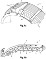
- the picture 1a shows a first perspective view of a cooling system 1 for the low pressure turbine casing of a turbomachine according to the state of the art.
- the picture 1a shows a turbomachine casing 2, a cooling system 1 for cooling the casing 2 comprising a plurality of cooling tubes 3, a supply box 4 supplying air to the plurality of cooling tubes, a plurality of fixing plates 5 for holding the cooling tubes 3 in position around the casing 2.
- the figure 1b shows a second perspective view of the cooling system 1 for the turbomachine casing according to the state of the art.
- the figure 1b shows more particularly a fixing plate under which a plurality of collars 6 are fixed, each collar 6 surrounding a cooling tube 3.
- a certain play (in the radial direction of the turbine) is provided between the fixing collars or the cooling tubes and the outer casing of the casing, in particular to avoid any contact of the parts (fixing collars, cooling tubes, casing) which could cause damage.
- the clearance between the cooling tubes and the outer casing casing must be as small as possible to position the cooling tubes as close as possible to the casing casing and to optimize its cooling.
- the current technical difficulty is to find a good compromise of radial positioning of the cooling tubes to avoid wear of the parts while making the cooling system as efficient as possible. Indeed, an optimal play is difficult to guarantee and to control because the casing and the cooling tubes are large diameter parts and the various intermediate parts intervening in the maintenance of the tubes cause an accumulation of tolerances which consequently increase the minimum play. eligible.
- the document FR1454790 describes for example a solution making it possible to better control the positioning of the cooling tube by reducing the number of intermediate parts for holding the cooling tubes. Such a solution makes it possible in particular to minimize the accumulation of tolerances linked to each intermediate part and therefore to better control the positioning of the cooling tubes.
- the invention offers a solution to the problems mentioned above, by proposing a holding device allowing fine and precise adjustment of the position of the cooling tubes during assembly around the casing so as to control the play between the cooling tubes and the casing envelope depending in particular actual dimensional constraints of the assembled parts and engine performance determined during test campaigns.
- the subject of the invention is a device for holding at least one cooling tube of a turbomachine casing cooling system, the casing extending around an axial direction of the turbomachine, the device holding device comprising a fixing plate adapted to be secured to the casing and a holding element for the cooling tube, said holding device being characterized in that it comprises an adjustment means configured to adjust the relative position of said holding element by relative to said fixing plate and to damp a relative movement between the holding element and the fixing plate.
- the present invention also relates to a turbomachine casing cooling system comprising a cooling tube; a device for holding at least one cooling tube according to the invention, said cooling tube being integral with said holding device by brazing.
- the turbomachine casing cooling system comprises a plurality of cooling tubes, a plurality of holding devices, each holding device of said plurality ensuring the holding and simultaneous adjustment of the position of two cooling adjacent to the crankcase.
- the invention also relates to a low-pressure turbine casing of a turbomachine, characterized in that it comprises a cooling system according to the invention arranged radially externally with respect to the casing.
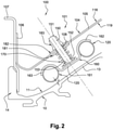
- the figure 2 is a partial sectional view of an exemplary embodiment of a cooling system 100 by air jets according to the invention mounted around a casing 10 of a turbomachine turbine.
- the housing 10 is a low pressure turbine housing.
- the cooling system 100 in the example shown is an LPTACC (Low Pressure Turbine Active Clearance Control) cooling device, for controlling clearances for low pressure turbines.
- LPTACC Low Pressure Turbine Active Clearance Control
- the cooling tubes 120 and the holding device 101 constitute the cooling system 100 of the casing 10 of the low pressure turbine.
- Such a system could also be applied to an LPTCC cooling device without departing from the scope of the invention.
- the two cooling tubes 120 have small openings not visible on the figure 2 .
- the supply units supply relatively cool air with respect to the casing 10 to the cooling tubes 120, which send the air thus available to the outer face 11 of the casing 10 through the small openings (not visible in the figure). ).
- the two supply boxes are arranged diametrically opposite on the casing 10.
- each zone of the cooling tubes 120 is supplied with air by a supply box located less than a quarter turn from the casing 10 , which makes it possible to have a flow of air sent via the small openings of the cooling tubes 120 sufficient whatever the zone considered of the cooling tubes 120.
- the holding device 101 comprises in particular a fixing plate 104 having a main part 105, a first end 106 and a second end (not shown).
- the fixing plate 104 is fixed to the casing 10 by means of intermediate plates 107 fixed to the ends of said fixing plate 104.
- the fixing plate 104 is fixed to the intermediate plates 107 for example by riveting or else by bolting.
- the casing 10 has a body 13 and side flanges 14 (a single flange being shown in picture 2 ). Each intermediate plate 105 is secured to the casing 10 at the side edges 14 of the casing 10, for example by riveting or by bolting.
- the main part 105 of the fixing plate 104 has an outer face 118, an inner face 119, and at least one through opening 108.
- the main part 105 of the fixing plate 104 may comprise a portion or a plurality of portions, for example with recesses as illustrated in the document FR1258238 .
- Each portion is generally planar and extends over the entire width of the main part 105 and two consecutive portions form an angle so that the main wall 104 thus follows the general shape of the casing 10 thanks to its different portions and to the angles that they form between themselves and/or with each of the two ends.
- the holding device 101 comprises an adjustment means making it possible to adjust the relative position of the cooling tubes 120 with respect to the fixing plate 104 and to dampen the relative movements between the cooling tubes 120 and the fixing plate 104.
- the adjustment means comprises a body 150 passing through said at least one opening 108.
- the body 150 is for example of cylindrical shape.
- the body 150 is movable in translation through said opening 108 and more precisely in a direction transverse to the plane formed by the opening 108 or by the portion on which the opening 108 is provided.
- the relative position of the body 150 with respect to the fixing plate 108 is adjustable via a screwing element 183 detailed below.
- the body 150 of cylindrical shape has a first end 151 and a second end 152.
- the second end 152 is integral with a support 160 allowing the attachment of at least one cooling tube 120.
- the support element 160 is for example a preformed support plate.
- the retaining plate 160 is for example obtained by forming and has a generally planar central part 161 and two ends 162, 163 in the form of half-rings intended to marry and to cover, at least partially, the annular shape of two tubes of cooling 120 adjacent.
- the cooling tubes 120 are secured to the retaining plate 160, for example by brazing.
- the retaining plate 160 advantageously makes it possible to secure the cooling tubes at the level of a radially outer part of the cooling tubes, that is to say on the side of the fixing plate 104, in particular so as to avoid the presence of a part or an additional element between the cooling tube 120 and the casing 10, and so as to be able to bring the cooling tubes 120 closer to the casing 10 for the optimization of the cooling of the latter.
- the retaining plate 160 covers at least partially the periphery of the cooling tubes and only a radially outer part of the cooling tubes 120, in particular the periphery of the cooling tubes facing the fixing plate 104.
- the holding plate 160 makes it possible to secure two cooling tubes 120 by means of a single and same holding plate 160.
- two cooling tubes are held and positioned circumferentially adjacent cooling by producing only an opening 108 in the fixing plate 108.
- the fixing plate 108 according to the invention will have fewer openings 108 and less grip than a fixing plate according to the state of the art.
- it is also envisaged to produce a retaining element making it possible to individually secure a cooling tube so as to improve the precision of adjustment of the radial position of the cooling tubes 120 with respect to the casing 10.
- the second end 152 of the cylindrical body 150 has a cylindrical cup 153 whose axis of revolution is oriented along the longitudinal axis of the cylindrical body 150.
- the cylindrical cup 153 is for example secured to the cylindrical body 150 by brazing.
- the cylindrical cup 153 makes it possible in particular to form a support element and to create a sufficient contact surface for the brazing of the holding element 160.
- the cylindrical cup 153 forms a support element for a return spring 170.
- the return spring 170 is a compression spring mounted under the fixing plate and more precisely between the cylindrical cup 153 of the second end 152 of the cylindrical body 150 and the inner face 119 of the fixing plate 104.
- a first washer 181 is interposed between the return spring 170 and the inner face 119 of the fixing plate 104.
- the return spring 170 bears directly on the first washer 181 and not on the fixing plate 104, in particular to avoid the phenomena of wear.
- the return spring 170 is an elastic element participating in the adjustment of the position of the cylindrical body 150, and therefore of the holding element 160 of the integral cooling tubes 120 and making it possible to damp the relative movements between the cooling tubes 120 and the fixing plate 104, the relative movements coming in particular from the differential expansions between the various elements of the cooling system and the casing 10.
- the return spring 170 also makes it possible to damp the vibrations of the turbomachine thus avoiding a rupture of the cooling system Operating.
- a screwing element 183 such as a nut, cooperates with a threaded portion of the cylindrical body 150 provided for example at the level of the first end 151 of the body 150.
- the screwing element 183 has a braking means making it possible to prevent any rotation thereof under the effect of vibrations.
- the screwing element 183 is for example a self-locking nut.
- the return spring 170, the nut 183 cooperating with the threaded part of the body 150 form the means for adjusting the holding device 101 making it possible to modify the position of the holding element 160 and of the cooling tubes with respect to the sheet. fixing 104, and relative to the housing 10.
- a second washer 182 is inserted between the nut 183 and the outer face 118 of the fixing plate 104, so that the base of the nut 183 is in contact with the second washer 182 and not directly with the fixing plate. 104, in particular to avoid wear phenomena.
- Said at least one opening 108 formed in the fixing plate 104 is advantageously an opening of oblong shape thus allowing movements of the cylindrical body 150, and of the holding element 160, in a plane orthogonal to the axis of the opening. 108 so as to allow differential expansion of the cooling tubes 120 relative to the housing 10 during operation.
- the holding device it is possible to precisely modify the relative position of the holding element 160, and therefore of the cooling tubes 120, with respect to the casing 10 by a simple rotation of the nut 183.
- the screwing of the nut 183 causes the cooling tubes 120 to move away from the casing 10, the clearance J between the cooling tubes 120 and the housing 10.
- unscrewing the nut 183 causes the cooling tubes 120 to move closer to the housing 10, the clearance J between the cooling tubes 120 and the housing 10.
- the return spring 170 makes it possible to exert a constant thrust on the retaining element 160 so that the nut 183 is constantly bearing on the washer 182, in particular to guarantee correct positioning of the tubes of D cooling 120.
- the holding device 101 according to the invention therefore makes it possible to carry out a precise, simple, effective adjustment by controlling the clearance J between the casing 10 and each cooling tube 120 or group of several cooling tubes 120 (for example two cooling tubes as shown on the picture 2 ) over there removal of a fixing collar completely surrounding the cooling tube.
- the holding device according to the invention makes it possible to guarantee a controlled positioning of the cooling tubes 120 with respect to the casing 10 individually (that is to say tube by tube) or in a group (by group of several cooling tubes). Thanks to the invention, the positioning of the cooling tubes 120 is controlled, which makes it possible to improve the cooling of the casing while minimizing the risks of contact between the cooling tubes 120 and the casing 10 and therefore the wear of the casing 10 .
Landscapes
- Engineering & Computer Science (AREA)
- Mechanical Engineering (AREA)
- General Engineering & Computer Science (AREA)
- Chemical & Material Sciences (AREA)
- Combustion & Propulsion (AREA)
- Turbine Rotor Nozzle Sealing (AREA)
Applications Claiming Priority (2)
| Application Number | Priority Date | Filing Date | Title |
|---|---|---|---|
| FR1760145A FR3073007B1 (fr) | 2017-10-27 | 2017-10-27 | Dispositif de maintien d'un tube de refroidissement pour carter de turbomachine |
| PCT/FR2018/052655 WO2019081861A1 (fr) | 2017-10-27 | 2018-10-25 | Dispositif de maintien d'un tube de refroidissement pour carter de turbomachine |
Publications (2)
| Publication Number | Publication Date |
|---|---|
| EP3701128A1 EP3701128A1 (fr) | 2020-09-02 |
| EP3701128B1 true EP3701128B1 (fr) | 2022-02-23 |
Family
ID=60923691
Family Applications (1)
| Application Number | Title | Priority Date | Filing Date |
|---|---|---|---|
| EP18800727.2A Active EP3701128B1 (fr) | 2017-10-27 | 2018-10-25 | Dispositif de maintien d'un tube de refroidissement pour carter de turbomachine |
Country Status (7)
| Country | Link |
|---|---|
| US (1) | US11098613B2 (ja) |
| EP (1) | EP3701128B1 (ja) |
| JP (1) | JP7219763B2 (ja) |
| CN (1) | CN111279053B (ja) |
| CA (1) | CA3079641A1 (ja) |
| FR (1) | FR3073007B1 (ja) |
| WO (1) | WO2019081861A1 (ja) |
Families Citing this family (5)
| Publication number | Priority date | Publication date | Assignee | Title |
|---|---|---|---|---|
| FR3085719B1 (fr) * | 2018-09-06 | 2021-04-16 | Safran Aircraft Engines | Boitier d'alimentation en air sous pression d'un dispositif de refroidissement par jets d'air |
| FR3089560B1 (fr) * | 2018-12-06 | 2021-01-22 | Safran Aircraft Engines | Dispositif de maintien d'un tube de refroidissement pour carter de turbomachine |
| FR3093129B1 (fr) * | 2019-02-25 | 2021-01-29 | Safran Aircraft Engines | Dispositif de maintien d’au moins un tube de refroidissement à un carter de turbomachine et son procédé de montage |
| FR3099800B1 (fr) * | 2019-08-09 | 2021-07-09 | Safran Aircraft Engines | Dispositif d'accrochage d'un boîtier d'alimentation en air d'un dispositif de refroidissement d'un carter de turbomachine |
| FR3137406A1 (fr) * | 2022-07-04 | 2024-01-05 | Safran Aircraft Engines | Carter de turbine de turboreacteur equipe de dispositifs mobiles de fixation de tubes de refroidissement |
Family Cites Families (32)
| Publication number | Priority date | Publication date | Assignee | Title |
|---|---|---|---|---|
| FR1258238A (fr) | 1959-10-10 | 1961-04-14 | Thermostat perfectionné | |
| FR1351676A (fr) | 1963-02-12 | 1964-02-07 | Peter Uhren G M B H | Chronomètre pour la mesure de courts intervalles de temps prédéterminés |
| US3330313A (en) | 1965-02-25 | 1967-07-11 | Emco Wheaton | Supply and receiver coupler |
| US4859142A (en) * | 1988-02-01 | 1989-08-22 | United Technologies Corporation | Turbine clearance control duct arrangement |
| US5540547A (en) * | 1994-06-23 | 1996-07-30 | General Electric Company | Method and apparatus for damping vibrations of external tubing of a gas turbine engine |
| JP3493764B2 (ja) * | 1994-11-18 | 2004-02-03 | 石川島播磨重工業株式会社 | ジェットエンジン用アフタバーナのフラップ取付構造 |
| FR2766232B1 (fr) * | 1997-07-18 | 1999-08-20 | Snecma | Dispositif de refroidissement ou d'echauffement d'un carter circulaire |
| US5867976A (en) * | 1997-08-01 | 1999-02-09 | General Electric Company | Self-retained borescope plug |
| US6185925B1 (en) * | 1999-02-12 | 2001-02-13 | General Electric Company | External cooling system for turbine frame |
| FR2816352B1 (fr) * | 2000-11-09 | 2003-01-31 | Snecma Moteurs | Ensemble de ventilation d'un anneau de stator |
| JP3951688B2 (ja) * | 2001-12-03 | 2007-08-01 | 石川島播磨重工業株式会社 | エンジンケース用冷却装置及びガスタービンエンジン |
| US8801370B2 (en) * | 2006-10-12 | 2014-08-12 | General Electric Company | Turbine case impingement cooling for heavy duty gas turbines |
| US7819626B2 (en) * | 2006-10-13 | 2010-10-26 | General Electric Company | Plasma blade tip clearance control |
| US7914254B2 (en) * | 2007-02-13 | 2011-03-29 | General Electric Company | Integrated support/thermocouple housing for impingement cooling manifolds and cooling method |
| GB2462069B (en) * | 2008-07-21 | 2011-11-02 | Rolls Royce Plc | Mounting assembly |
| US8079804B2 (en) * | 2008-09-18 | 2011-12-20 | Siemens Energy, Inc. | Cooling structure for outer surface of a gas turbine case |
| US8123406B2 (en) * | 2008-11-10 | 2012-02-28 | General Electric Company | Externally adjustable impingement cooling manifold mount and thermocouple housing |
| US8342798B2 (en) * | 2009-07-28 | 2013-01-01 | General Electric Company | System and method for clearance control in a rotary machine |
| US8573078B2 (en) * | 2010-11-23 | 2013-11-05 | General Electric Company | System and method for positioning a sensor |
| FR2977276B1 (fr) * | 2011-06-30 | 2016-12-09 | Snecma | Agencement pour le raccordement d'un conduit a un boitier de distribution d'air |
| US9719372B2 (en) * | 2012-05-01 | 2017-08-01 | General Electric Company | Gas turbomachine including a counter-flow cooling system and method |
| EP2664746A3 (en) * | 2012-05-16 | 2014-04-23 | General Electric Company | Systems and methods for adjusting clearances in turbines |
| US9341074B2 (en) * | 2012-07-25 | 2016-05-17 | General Electric Company | Active clearance control manifold system |
| FR2995022B1 (fr) * | 2012-09-04 | 2017-11-24 | Snecma | Dispositif de fixation d'un systeme de refroidissement pour carter de turboreacteur d'aeronef |
| FR3002590B1 (fr) * | 2013-02-26 | 2015-04-03 | Snecma | Dispositif de refroidissement pour carter de turboreacteur d'aeronef comportant un dispositif de maintien |
| FR3006373B1 (fr) * | 2013-05-31 | 2015-05-22 | Snecma | Carter de turbomachine comportant un orifice d'endoscopie |
| US9797259B2 (en) * | 2014-03-07 | 2017-10-24 | Siemens Energy, Inc. | Turbine airfoil cooling system with cooling systems using high and low pressure cooling fluids |
| FR3021700B1 (fr) * | 2014-05-27 | 2016-07-01 | Snecma | Dispositif de maintien d'un tube de refroidissement pour carter de turboreacteur |
| US9869196B2 (en) * | 2014-06-24 | 2018-01-16 | General Electric Company | Gas turbine engine spring mounted manifold |
| US9695705B2 (en) * | 2014-10-29 | 2017-07-04 | General Electric Company | Systems and methods for controlling rotor to stator clearances in a steam turbine |
| US20170114667A1 (en) * | 2015-10-23 | 2017-04-27 | General Electric Company | Active clearance control with integral double wall heat shielding |
| CN205277511U (zh) * | 2015-11-24 | 2016-06-01 | 中国燃气涡轮研究院 | 用于涡轮主动间隙控制的冷却结构 |
-
2017
- 2017-10-27 FR FR1760145A patent/FR3073007B1/fr active Active
-
2018
- 2018-10-25 CN CN201880069796.2A patent/CN111279053B/zh active Active
- 2018-10-25 CA CA3079641A patent/CA3079641A1/fr active Pending
- 2018-10-25 JP JP2020523392A patent/JP7219763B2/ja active Active
- 2018-10-25 WO PCT/FR2018/052655 patent/WO2019081861A1/fr unknown
- 2018-10-25 US US16/758,723 patent/US11098613B2/en active Active
- 2018-10-25 EP EP18800727.2A patent/EP3701128B1/fr active Active
Also Published As
| Publication number | Publication date |
|---|---|
| RU2020117058A (ru) | 2021-11-29 |
| FR3073007B1 (fr) | 2019-09-27 |
| WO2019081861A1 (fr) | 2019-05-02 |
| CN111279053B (zh) | 2022-07-12 |
| CA3079641A1 (fr) | 2019-05-02 |
| RU2020117058A3 (ja) | 2022-03-09 |
| FR3073007A1 (fr) | 2019-05-03 |
| EP3701128A1 (fr) | 2020-09-02 |
| US11098613B2 (en) | 2021-08-24 |
| BR112020008196A2 (pt) | 2020-10-20 |
| US20200362725A1 (en) | 2020-11-19 |
| JP7219763B2 (ja) | 2023-02-08 |
| JP2021500507A (ja) | 2021-01-07 |
| CN111279053A (zh) | 2020-06-12 |
Similar Documents
| Publication | Publication Date | Title |
|---|---|---|
| EP3701128B1 (fr) | Dispositif de maintien d'un tube de refroidissement pour carter de turbomachine | |
| EP1696134B1 (fr) | Dispositif de réglage du centrage d'un anneau de synchronisation de commande d'aubes pivotantes de turbomachine | |
| FR3018548A1 (fr) | Turboreacteur a conduit de decharge | |
| EP3230602B1 (fr) | Anneau de commande d'un étage d'aubes à calage variable pour une turbomachine | |
| WO2015079144A1 (fr) | Dispositif de guidage d'aubes de redresseur a angle de calage variable de turbomachine et procédé d'assemblage d'un tel dispositif. | |
| FR2943313A1 (fr) | Helice non carenee a pales a calage variable pour une turbomachine | |
| FR3077097A1 (fr) | Dispositif de refroidissement pour une turbine d'une turbomachine | |
| WO2014131978A1 (fr) | Dispositif de refroidissement pour carter de turboreacteur d'aeronef comportant un dispositif de maintien | |
| FR2995022A1 (fr) | Dispositif de fixation d'un systeme de refroidissement pour carter de turboreacteur d'aeronef | |
| EP3382210B1 (fr) | Aube à calage variable de turbomachine, virole de turbomachine, système d'aubes à calage variable, compresseur et turbomachine associés | |
| FR3062876A1 (fr) | Compresseur haute pression pour turbomachine | |
| FR3093129A1 (fr) | Dispositif de maintien d’au moins un tube de refroidissement à un carter de turbomachine et son procédé de montage | |
| FR3008135A1 (fr) | Centrage d'une piece a l'interieur d'un arbre de rotor dans une turbomachine | |
| FR2882577A1 (fr) | Dispositif de reglage du centrage d'un anneau de synchronisation de commande d'aubes pivotantes de turbomachine | |
| EP3663534B1 (fr) | Dispositif de maintien d'un tube de refroidissement pour carter de turbomachine | |
| EP4010563B1 (fr) | Dispositif de refroidissement par jets d'air d'un carter externe de turbomachine et turbomachine équipée d'un tel dispositif | |
| FR3077851A1 (fr) | Ensemble de commande d'un etage d'aubes a calage variable pour une turbomachine | |
| EP3710679B1 (fr) | Dispositif de maintien d'un organe de prelevement d'air radial centripete | |
| FR3093539A1 (fr) | Dispositif de maintien de tube de refroidissement par jet d'air, turbomachine pour aéronef l'ayant | |
| FR3082227A1 (fr) | Dispositif pilote de refroidissement pour une turbine d'une turbomachine | |
| FR3053383B1 (fr) | Clinquant de retention de douilles d'anneaux de commande d'aubes a calage variable et turboreacteur l'incorporant | |
| FR3029564A1 (fr) | Anneau de commande d'un etage d'aubes a calage variable pour une turbomachine | |
| FR2991387A1 (fr) | Turbomachine, telle qu'un turboreacteur ou un turbopropulseur d'avion | |
| FR2944774A1 (fr) | Helice non carenee a pales a calage variable pour une turbomachine | |
| FR3079553A1 (fr) | Ensemble pour turbomachine |
Legal Events
| Date | Code | Title | Description |
|---|---|---|---|
| STAA | Information on the status of an ep patent application or granted ep patent |
Free format text: STATUS: UNKNOWN |
|
| STAA | Information on the status of an ep patent application or granted ep patent |
Free format text: STATUS: THE INTERNATIONAL PUBLICATION HAS BEEN MADE |
|
| PUAI | Public reference made under article 153(3) epc to a published international application that has entered the european phase |
Free format text: ORIGINAL CODE: 0009012 |
|
| STAA | Information on the status of an ep patent application or granted ep patent |
Free format text: STATUS: REQUEST FOR EXAMINATION WAS MADE |
|
| 17P | Request for examination filed |
Effective date: 20200416 |
|
| AK | Designated contracting states |
Kind code of ref document: A1 Designated state(s): AL AT BE BG CH CY CZ DE DK EE ES FI FR GB GR HR HU IE IS IT LI LT LU LV MC MK MT NL NO PL PT RO RS SE SI SK SM TR |
|
| AX | Request for extension of the european patent |
Extension state: BA ME |
|
| DAV | Request for validation of the european patent (deleted) | ||
| DAX | Request for extension of the european patent (deleted) | ||
| GRAP | Despatch of communication of intention to grant a patent |
Free format text: ORIGINAL CODE: EPIDOSNIGR1 |
|
| STAA | Information on the status of an ep patent application or granted ep patent |
Free format text: STATUS: GRANT OF PATENT IS INTENDED |
|
| INTG | Intention to grant announced |
Effective date: 20211109 |
|
| GRAS | Grant fee paid |
Free format text: ORIGINAL CODE: EPIDOSNIGR3 |
|
| GRAA | (expected) grant |
Free format text: ORIGINAL CODE: 0009210 |
|
| STAA | Information on the status of an ep patent application or granted ep patent |
Free format text: STATUS: THE PATENT HAS BEEN GRANTED |
|
| AK | Designated contracting states |
Kind code of ref document: B1 Designated state(s): AL AT BE BG CH CY CZ DE DK EE ES FI FR GB GR HR HU IE IS IT LI LT LU LV MC MK MT NL NO PL PT RO RS SE SI SK SM TR |
|
| REG | Reference to a national code |
Ref country code: GB Ref legal event code: FG4D Free format text: NOT ENGLISH |
|
| REG | Reference to a national code |
Ref country code: CH Ref legal event code: EP |
|
| REG | Reference to a national code |
Ref country code: DE Ref legal event code: R096 Ref document number: 602018031324 Country of ref document: DE |
|
| REG | Reference to a national code |
Ref country code: AT Ref legal event code: REF Ref document number: 1470616 Country of ref document: AT Kind code of ref document: T Effective date: 20220315 |
|
| REG | Reference to a national code |
Ref country code: IE Ref legal event code: FG4D Free format text: LANGUAGE OF EP DOCUMENT: FRENCH |
|
| REG | Reference to a national code |
Ref country code: SE Ref legal event code: TRGR |
|
| REG | Reference to a national code |
Ref country code: LT Ref legal event code: MG9D |
|
| REG | Reference to a national code |
Ref country code: NL Ref legal event code: MP Effective date: 20220223 |
|
| REG | Reference to a national code |
Ref country code: AT Ref legal event code: MK05 Ref document number: 1470616 Country of ref document: AT Kind code of ref document: T Effective date: 20220223 |
|
| PG25 | Lapsed in a contracting state [announced via postgrant information from national office to epo] |
Ref country code: RS Free format text: LAPSE BECAUSE OF FAILURE TO SUBMIT A TRANSLATION OF THE DESCRIPTION OR TO PAY THE FEE WITHIN THE PRESCRIBED TIME-LIMIT Effective date: 20220223 Ref country code: PT Free format text: LAPSE BECAUSE OF FAILURE TO SUBMIT A TRANSLATION OF THE DESCRIPTION OR TO PAY THE FEE WITHIN THE PRESCRIBED TIME-LIMIT Effective date: 20220623 Ref country code: NO Free format text: LAPSE BECAUSE OF FAILURE TO SUBMIT A TRANSLATION OF THE DESCRIPTION OR TO PAY THE FEE WITHIN THE PRESCRIBED TIME-LIMIT Effective date: 20220523 Ref country code: NL Free format text: LAPSE BECAUSE OF FAILURE TO SUBMIT A TRANSLATION OF THE DESCRIPTION OR TO PAY THE FEE WITHIN THE PRESCRIBED TIME-LIMIT Effective date: 20220223 Ref country code: LT Free format text: LAPSE BECAUSE OF FAILURE TO SUBMIT A TRANSLATION OF THE DESCRIPTION OR TO PAY THE FEE WITHIN THE PRESCRIBED TIME-LIMIT Effective date: 20220223 Ref country code: HR Free format text: LAPSE BECAUSE OF FAILURE TO SUBMIT A TRANSLATION OF THE DESCRIPTION OR TO PAY THE FEE WITHIN THE PRESCRIBED TIME-LIMIT Effective date: 20220223 Ref country code: ES Free format text: LAPSE BECAUSE OF FAILURE TO SUBMIT A TRANSLATION OF THE DESCRIPTION OR TO PAY THE FEE WITHIN THE PRESCRIBED TIME-LIMIT Effective date: 20220223 Ref country code: BG Free format text: LAPSE BECAUSE OF FAILURE TO SUBMIT A TRANSLATION OF THE DESCRIPTION OR TO PAY THE FEE WITHIN THE PRESCRIBED TIME-LIMIT Effective date: 20220523 |
|
| PG25 | Lapsed in a contracting state [announced via postgrant information from national office to epo] |
Ref country code: PL Free format text: LAPSE BECAUSE OF FAILURE TO SUBMIT A TRANSLATION OF THE DESCRIPTION OR TO PAY THE FEE WITHIN THE PRESCRIBED TIME-LIMIT Effective date: 20220223 Ref country code: LV Free format text: LAPSE BECAUSE OF FAILURE TO SUBMIT A TRANSLATION OF THE DESCRIPTION OR TO PAY THE FEE WITHIN THE PRESCRIBED TIME-LIMIT Effective date: 20220223 Ref country code: GR Free format text: LAPSE BECAUSE OF FAILURE TO SUBMIT A TRANSLATION OF THE DESCRIPTION OR TO PAY THE FEE WITHIN THE PRESCRIBED TIME-LIMIT Effective date: 20220524 Ref country code: FI Free format text: LAPSE BECAUSE OF FAILURE TO SUBMIT A TRANSLATION OF THE DESCRIPTION OR TO PAY THE FEE WITHIN THE PRESCRIBED TIME-LIMIT Effective date: 20220223 Ref country code: AT Free format text: LAPSE BECAUSE OF FAILURE TO SUBMIT A TRANSLATION OF THE DESCRIPTION OR TO PAY THE FEE WITHIN THE PRESCRIBED TIME-LIMIT Effective date: 20220223 |
|
| PG25 | Lapsed in a contracting state [announced via postgrant information from national office to epo] |
Ref country code: IS Free format text: LAPSE BECAUSE OF FAILURE TO SUBMIT A TRANSLATION OF THE DESCRIPTION OR TO PAY THE FEE WITHIN THE PRESCRIBED TIME-LIMIT Effective date: 20220623 |
|
| PG25 | Lapsed in a contracting state [announced via postgrant information from national office to epo] |
Ref country code: SM Free format text: LAPSE BECAUSE OF FAILURE TO SUBMIT A TRANSLATION OF THE DESCRIPTION OR TO PAY THE FEE WITHIN THE PRESCRIBED TIME-LIMIT Effective date: 20220223 Ref country code: SK Free format text: LAPSE BECAUSE OF FAILURE TO SUBMIT A TRANSLATION OF THE DESCRIPTION OR TO PAY THE FEE WITHIN THE PRESCRIBED TIME-LIMIT Effective date: 20220223 Ref country code: RO Free format text: LAPSE BECAUSE OF FAILURE TO SUBMIT A TRANSLATION OF THE DESCRIPTION OR TO PAY THE FEE WITHIN THE PRESCRIBED TIME-LIMIT Effective date: 20220223 Ref country code: EE Free format text: LAPSE BECAUSE OF FAILURE TO SUBMIT A TRANSLATION OF THE DESCRIPTION OR TO PAY THE FEE WITHIN THE PRESCRIBED TIME-LIMIT Effective date: 20220223 Ref country code: DK Free format text: LAPSE BECAUSE OF FAILURE TO SUBMIT A TRANSLATION OF THE DESCRIPTION OR TO PAY THE FEE WITHIN THE PRESCRIBED TIME-LIMIT Effective date: 20220223 Ref country code: CZ Free format text: LAPSE BECAUSE OF FAILURE TO SUBMIT A TRANSLATION OF THE DESCRIPTION OR TO PAY THE FEE WITHIN THE PRESCRIBED TIME-LIMIT Effective date: 20220223 |
|
| REG | Reference to a national code |
Ref country code: DE Ref legal event code: R097 Ref document number: 602018031324 Country of ref document: DE |
|
| PG25 | Lapsed in a contracting state [announced via postgrant information from national office to epo] |
Ref country code: AL Free format text: LAPSE BECAUSE OF FAILURE TO SUBMIT A TRANSLATION OF THE DESCRIPTION OR TO PAY THE FEE WITHIN THE PRESCRIBED TIME-LIMIT Effective date: 20220223 |
|
| PLBE | No opposition filed within time limit |
Free format text: ORIGINAL CODE: 0009261 |
|
| STAA | Information on the status of an ep patent application or granted ep patent |
Free format text: STATUS: NO OPPOSITION FILED WITHIN TIME LIMIT |
|
| 26N | No opposition filed |
Effective date: 20221124 |
|
| PG25 | Lapsed in a contracting state [announced via postgrant information from national office to epo] |
Ref country code: SI Free format text: LAPSE BECAUSE OF FAILURE TO SUBMIT A TRANSLATION OF THE DESCRIPTION OR TO PAY THE FEE WITHIN THE PRESCRIBED TIME-LIMIT Effective date: 20220223 |
|
| PG25 | Lapsed in a contracting state [announced via postgrant information from national office to epo] |
Ref country code: MC Free format text: LAPSE BECAUSE OF FAILURE TO SUBMIT A TRANSLATION OF THE DESCRIPTION OR TO PAY THE FEE WITHIN THE PRESCRIBED TIME-LIMIT Effective date: 20220223 |
|
| REG | Reference to a national code |
Ref country code: CH Ref legal event code: PL |
|
| REG | Reference to a national code |
Ref country code: BE Ref legal event code: MM Effective date: 20221031 |
|
| PG25 | Lapsed in a contracting state [announced via postgrant information from national office to epo] |
Ref country code: LU Free format text: LAPSE BECAUSE OF NON-PAYMENT OF DUE FEES Effective date: 20221025 |
|
| PG25 | Lapsed in a contracting state [announced via postgrant information from national office to epo] |
Ref country code: LI Free format text: LAPSE BECAUSE OF NON-PAYMENT OF DUE FEES Effective date: 20221031 Ref country code: CH Free format text: LAPSE BECAUSE OF NON-PAYMENT OF DUE FEES Effective date: 20221031 |
|
| PG25 | Lapsed in a contracting state [announced via postgrant information from national office to epo] |
Ref country code: BE Free format text: LAPSE BECAUSE OF NON-PAYMENT OF DUE FEES Effective date: 20221031 |
|
| PG25 | Lapsed in a contracting state [announced via postgrant information from national office to epo] |
Ref country code: IE Free format text: LAPSE BECAUSE OF NON-PAYMENT OF DUE FEES Effective date: 20221025 |
|
| PGFP | Annual fee paid to national office [announced via postgrant information from national office to epo] |
Ref country code: IT Payment date: 20230920 Year of fee payment: 6 Ref country code: GB Payment date: 20230920 Year of fee payment: 6 |
|
| PGFP | Annual fee paid to national office [announced via postgrant information from national office to epo] |
Ref country code: SE Payment date: 20230922 Year of fee payment: 6 Ref country code: FR Payment date: 20230920 Year of fee payment: 6 |
|
| PGFP | Annual fee paid to national office [announced via postgrant information from national office to epo] |
Ref country code: DE Payment date: 20230920 Year of fee payment: 6 |
|
| PG25 | Lapsed in a contracting state [announced via postgrant information from national office to epo] |
Ref country code: CY Free format text: LAPSE BECAUSE OF FAILURE TO SUBMIT A TRANSLATION OF THE DESCRIPTION OR TO PAY THE FEE WITHIN THE PRESCRIBED TIME-LIMIT Effective date: 20220223 |
|
| PG25 | Lapsed in a contracting state [announced via postgrant information from national office to epo] |
Ref country code: MK Free format text: LAPSE BECAUSE OF FAILURE TO SUBMIT A TRANSLATION OF THE DESCRIPTION OR TO PAY THE FEE WITHIN THE PRESCRIBED TIME-LIMIT Effective date: 20220223 Ref country code: HU Free format text: LAPSE BECAUSE OF FAILURE TO SUBMIT A TRANSLATION OF THE DESCRIPTION OR TO PAY THE FEE WITHIN THE PRESCRIBED TIME-LIMIT; INVALID AB INITIO Effective date: 20181025 |