EP3701128B1 - Retention device for a cooling tube for a turbomachine case - Google Patents
Retention device for a cooling tube for a turbomachine case Download PDFInfo
- Publication number
- EP3701128B1 EP3701128B1 EP18800727.2A EP18800727A EP3701128B1 EP 3701128 B1 EP3701128 B1 EP 3701128B1 EP 18800727 A EP18800727 A EP 18800727A EP 3701128 B1 EP3701128 B1 EP 3701128B1
- Authority
- EP
- European Patent Office
- Prior art keywords
- cooling
- casing
- cooling tube
- retention
- turbomachine
- Prior art date
- Legal status (The legal status is an assumption and is not a legal conclusion. Google has not performed a legal analysis and makes no representation as to the accuracy of the status listed.)
- Active
Links
- 238000001816 cooling Methods 0.000 title claims description 142
- 230000014759 maintenance of location Effects 0.000 title claims 27
- 238000005219 brazing Methods 0.000 claims description 5
- 238000006073 displacement reaction Methods 0.000 claims 1
- 208000031968 Cadaver Diseases 0.000 description 5
- 238000009825 accumulation Methods 0.000 description 2
- 230000006835 compression Effects 0.000 description 1
- 238000007906 compression Methods 0.000 description 1
- 230000000694 effects Effects 0.000 description 1
- 238000012423 maintenance Methods 0.000 description 1
- 238000000034 method Methods 0.000 description 1
- 238000005457 optimization Methods 0.000 description 1
- 239000007787 solid Substances 0.000 description 1
- 238000011144 upstream manufacturing Methods 0.000 description 1
Images
Classifications
-
- F—MECHANICAL ENGINEERING; LIGHTING; HEATING; WEAPONS; BLASTING
- F02—COMBUSTION ENGINES; HOT-GAS OR COMBUSTION-PRODUCT ENGINE PLANTS
- F02C—GAS-TURBINE PLANTS; AIR INTAKES FOR JET-PROPULSION PLANTS; CONTROLLING FUEL SUPPLY IN AIR-BREATHING JET-PROPULSION PLANTS
- F02C7/00—Features, components parts, details or accessories, not provided for in, or of interest apart form groups F02C1/00 - F02C6/00; Air intakes for jet-propulsion plants
- F02C7/12—Cooling of plants
- F02C7/16—Cooling of plants characterised by cooling medium
- F02C7/18—Cooling of plants characterised by cooling medium the medium being gaseous, e.g. air
-
- F—MECHANICAL ENGINEERING; LIGHTING; HEATING; WEAPONS; BLASTING
- F01—MACHINES OR ENGINES IN GENERAL; ENGINE PLANTS IN GENERAL; STEAM ENGINES
- F01D—NON-POSITIVE DISPLACEMENT MACHINES OR ENGINES, e.g. STEAM TURBINES
- F01D25/00—Component parts, details, or accessories, not provided for in, or of interest apart from, other groups
- F01D25/08—Cooling; Heating; Heat-insulation
- F01D25/12—Cooling
-
- F—MECHANICAL ENGINEERING; LIGHTING; HEATING; WEAPONS; BLASTING
- F01—MACHINES OR ENGINES IN GENERAL; ENGINE PLANTS IN GENERAL; STEAM ENGINES
- F01D—NON-POSITIVE DISPLACEMENT MACHINES OR ENGINES, e.g. STEAM TURBINES
- F01D11/00—Preventing or minimising internal leakage of working-fluid, e.g. between stages
- F01D11/08—Preventing or minimising internal leakage of working-fluid, e.g. between stages for sealing space between rotor blade tips and stator
- F01D11/14—Adjusting or regulating tip-clearance, i.e. distance between rotor-blade tips and stator casing
- F01D11/20—Actively adjusting tip-clearance
- F01D11/24—Actively adjusting tip-clearance by selectively cooling-heating stator or rotor components
-
- F—MECHANICAL ENGINEERING; LIGHTING; HEATING; WEAPONS; BLASTING
- F01—MACHINES OR ENGINES IN GENERAL; ENGINE PLANTS IN GENERAL; STEAM ENGINES
- F01D—NON-POSITIVE DISPLACEMENT MACHINES OR ENGINES, e.g. STEAM TURBINES
- F01D25/00—Component parts, details, or accessories, not provided for in, or of interest apart from, other groups
- F01D25/24—Casings; Casing parts, e.g. diaphragms, casing fastenings
-
- F—MECHANICAL ENGINEERING; LIGHTING; HEATING; WEAPONS; BLASTING
- F05—INDEXING SCHEMES RELATING TO ENGINES OR PUMPS IN VARIOUS SUBCLASSES OF CLASSES F01-F04
- F05D—INDEXING SCHEME FOR ASPECTS RELATING TO NON-POSITIVE-DISPLACEMENT MACHINES OR ENGINES, GAS-TURBINES OR JET-PROPULSION PLANTS
- F05D2230/00—Manufacture
- F05D2230/20—Manufacture essentially without removing material
- F05D2230/23—Manufacture essentially without removing material by permanently joining parts together
- F05D2230/232—Manufacture essentially without removing material by permanently joining parts together by welding
- F05D2230/237—Brazing
-
- F—MECHANICAL ENGINEERING; LIGHTING; HEATING; WEAPONS; BLASTING
- F05—INDEXING SCHEMES RELATING TO ENGINES OR PUMPS IN VARIOUS SUBCLASSES OF CLASSES F01-F04
- F05D—INDEXING SCHEME FOR ASPECTS RELATING TO NON-POSITIVE-DISPLACEMENT MACHINES OR ENGINES, GAS-TURBINES OR JET-PROPULSION PLANTS
- F05D2250/00—Geometry
- F05D2250/40—Movement of components
- F05D2250/41—Movement of components with one degree of freedom
-
- F—MECHANICAL ENGINEERING; LIGHTING; HEATING; WEAPONS; BLASTING
- F05—INDEXING SCHEMES RELATING TO ENGINES OR PUMPS IN VARIOUS SUBCLASSES OF CLASSES F01-F04
- F05D—INDEXING SCHEME FOR ASPECTS RELATING TO NON-POSITIVE-DISPLACEMENT MACHINES OR ENGINES, GAS-TURBINES OR JET-PROPULSION PLANTS
- F05D2260/00—Function
- F05D2260/20—Heat transfer, e.g. cooling
- F05D2260/201—Heat transfer, e.g. cooling by impingement of a fluid
-
- F—MECHANICAL ENGINEERING; LIGHTING; HEATING; WEAPONS; BLASTING
- F05—INDEXING SCHEMES RELATING TO ENGINES OR PUMPS IN VARIOUS SUBCLASSES OF CLASSES F01-F04
- F05D—INDEXING SCHEME FOR ASPECTS RELATING TO NON-POSITIVE-DISPLACEMENT MACHINES OR ENGINES, GAS-TURBINES OR JET-PROPULSION PLANTS
- F05D2260/00—Function
- F05D2260/30—Retaining components in desired mutual position
-
- F—MECHANICAL ENGINEERING; LIGHTING; HEATING; WEAPONS; BLASTING
- F05—INDEXING SCHEMES RELATING TO ENGINES OR PUMPS IN VARIOUS SUBCLASSES OF CLASSES F01-F04
- F05D—INDEXING SCHEME FOR ASPECTS RELATING TO NON-POSITIVE-DISPLACEMENT MACHINES OR ENGINES, GAS-TURBINES OR JET-PROPULSION PLANTS
- F05D2260/00—Function
- F05D2260/50—Kinematic linkage, i.e. transmission of position
- F05D2260/52—Kinematic linkage, i.e. transmission of position involving springs
-
- F—MECHANICAL ENGINEERING; LIGHTING; HEATING; WEAPONS; BLASTING
- F05—INDEXING SCHEMES RELATING TO ENGINES OR PUMPS IN VARIOUS SUBCLASSES OF CLASSES F01-F04
- F05D—INDEXING SCHEME FOR ASPECTS RELATING TO NON-POSITIVE-DISPLACEMENT MACHINES OR ENGINES, GAS-TURBINES OR JET-PROPULSION PLANTS
- F05D2260/00—Function
- F05D2260/96—Preventing, counteracting or reducing vibration or noise
-
- Y—GENERAL TAGGING OF NEW TECHNOLOGICAL DEVELOPMENTS; GENERAL TAGGING OF CROSS-SECTIONAL TECHNOLOGIES SPANNING OVER SEVERAL SECTIONS OF THE IPC; TECHNICAL SUBJECTS COVERED BY FORMER USPC CROSS-REFERENCE ART COLLECTIONS [XRACs] AND DIGESTS
- Y02—TECHNOLOGIES OR APPLICATIONS FOR MITIGATION OR ADAPTATION AGAINST CLIMATE CHANGE
- Y02T—CLIMATE CHANGE MITIGATION TECHNOLOGIES RELATED TO TRANSPORTATION
- Y02T50/00—Aeronautics or air transport
- Y02T50/60—Efficient propulsion technologies, e.g. for aircraft
Definitions
- the technical field of the invention is, in general, that of turbomachines, and more particularly that of the cooling of various elements of a turbomachine, in particular the casings of the low-pressure turbine of the turbomachine.
- the present invention relates more particularly to a device for holding a cooling system by air jets of a low-pressure turbine casing of a turbomachine.
- a cooling device which involves a set of cooling tubes, also called cooling ramps, pierced with holes and arranged outside the casing. , most often by surrounding said casing, so that air, sucked in upstream of the turbomachine relative to the direction of gas flow in the turbomachine, is sent to the outer face of the casing.
- the cooling system is also composed of two boxes, arranged on either side of the casing, supplying the cooling tubes, so that each box supplies air to the cooling tubes surrounding the casing over approximately a quarter of its length. circumference.
- Cooling systems of the LPTCC Low Pressure Turbine Clearance Control
- the LPTCC system can be controlled by the FADEC (acronym for Full Authority Digital Engine Control, which designates a full authority digital engine governor for an aircraft engine); this is then referred to as active control, the system then being designated by the acronym LPTACC.
- active control the system then being designated by the acronym LPTACC.
- passive control LPTCC. Its main function is to regulate the clearance between the parts of the low pressure turbine by modulating the cooling and the air flow taken from the secondary flow for the cooling of the low pressure turbine casing.
- the cooling tubes of the LPTCC or LPTACC systems are held in position around the casing by the supply boxes and by fixing plates, integral with the casing.
- the fixing sheets are generally flat sheets under which are fixed fixing collars, also called shower collars.
- the fixing collars surround the cooling tubes and guarantee their positioning around the crankcase.
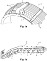
- the picture 1a shows a first perspective view of a cooling system 1 for the low pressure turbine casing of a turbomachine according to the state of the art.
- the picture 1a shows a turbomachine casing 2, a cooling system 1 for cooling the casing 2 comprising a plurality of cooling tubes 3, a supply box 4 supplying air to the plurality of cooling tubes, a plurality of fixing plates 5 for holding the cooling tubes 3 in position around the casing 2.
- the figure 1b shows a second perspective view of the cooling system 1 for the turbomachine casing according to the state of the art.
- the figure 1b shows more particularly a fixing plate under which a plurality of collars 6 are fixed, each collar 6 surrounding a cooling tube 3.
- a certain play (in the radial direction of the turbine) is provided between the fixing collars or the cooling tubes and the outer casing of the casing, in particular to avoid any contact of the parts (fixing collars, cooling tubes, casing) which could cause damage.
- the clearance between the cooling tubes and the outer casing casing must be as small as possible to position the cooling tubes as close as possible to the casing casing and to optimize its cooling.
- the current technical difficulty is to find a good compromise of radial positioning of the cooling tubes to avoid wear of the parts while making the cooling system as efficient as possible. Indeed, an optimal play is difficult to guarantee and to control because the casing and the cooling tubes are large diameter parts and the various intermediate parts intervening in the maintenance of the tubes cause an accumulation of tolerances which consequently increase the minimum play. eligible.
- the document FR1454790 describes for example a solution making it possible to better control the positioning of the cooling tube by reducing the number of intermediate parts for holding the cooling tubes. Such a solution makes it possible in particular to minimize the accumulation of tolerances linked to each intermediate part and therefore to better control the positioning of the cooling tubes.
- the invention offers a solution to the problems mentioned above, by proposing a holding device allowing fine and precise adjustment of the position of the cooling tubes during assembly around the casing so as to control the play between the cooling tubes and the casing envelope depending in particular actual dimensional constraints of the assembled parts and engine performance determined during test campaigns.
- the subject of the invention is a device for holding at least one cooling tube of a turbomachine casing cooling system, the casing extending around an axial direction of the turbomachine, the device holding device comprising a fixing plate adapted to be secured to the casing and a holding element for the cooling tube, said holding device being characterized in that it comprises an adjustment means configured to adjust the relative position of said holding element by relative to said fixing plate and to damp a relative movement between the holding element and the fixing plate.
- the present invention also relates to a turbomachine casing cooling system comprising a cooling tube; a device for holding at least one cooling tube according to the invention, said cooling tube being integral with said holding device by brazing.
- the turbomachine casing cooling system comprises a plurality of cooling tubes, a plurality of holding devices, each holding device of said plurality ensuring the holding and simultaneous adjustment of the position of two cooling adjacent to the crankcase.
- the invention also relates to a low-pressure turbine casing of a turbomachine, characterized in that it comprises a cooling system according to the invention arranged radially externally with respect to the casing.
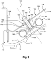
- the figure 2 is a partial sectional view of an exemplary embodiment of a cooling system 100 by air jets according to the invention mounted around a casing 10 of a turbomachine turbine.
- the housing 10 is a low pressure turbine housing.
- the cooling system 100 in the example shown is an LPTACC (Low Pressure Turbine Active Clearance Control) cooling device, for controlling clearances for low pressure turbines.
- LPTACC Low Pressure Turbine Active Clearance Control
- the cooling tubes 120 and the holding device 101 constitute the cooling system 100 of the casing 10 of the low pressure turbine.
- Such a system could also be applied to an LPTCC cooling device without departing from the scope of the invention.
- the two cooling tubes 120 have small openings not visible on the figure 2 .
- the supply units supply relatively cool air with respect to the casing 10 to the cooling tubes 120, which send the air thus available to the outer face 11 of the casing 10 through the small openings (not visible in the figure). ).
- the two supply boxes are arranged diametrically opposite on the casing 10.
- each zone of the cooling tubes 120 is supplied with air by a supply box located less than a quarter turn from the casing 10 , which makes it possible to have a flow of air sent via the small openings of the cooling tubes 120 sufficient whatever the zone considered of the cooling tubes 120.
- the holding device 101 comprises in particular a fixing plate 104 having a main part 105, a first end 106 and a second end (not shown).
- the fixing plate 104 is fixed to the casing 10 by means of intermediate plates 107 fixed to the ends of said fixing plate 104.
- the fixing plate 104 is fixed to the intermediate plates 107 for example by riveting or else by bolting.
- the casing 10 has a body 13 and side flanges 14 (a single flange being shown in picture 2 ). Each intermediate plate 105 is secured to the casing 10 at the side edges 14 of the casing 10, for example by riveting or by bolting.
- the main part 105 of the fixing plate 104 has an outer face 118, an inner face 119, and at least one through opening 108.
- the main part 105 of the fixing plate 104 may comprise a portion or a plurality of portions, for example with recesses as illustrated in the document FR1258238 .
- Each portion is generally planar and extends over the entire width of the main part 105 and two consecutive portions form an angle so that the main wall 104 thus follows the general shape of the casing 10 thanks to its different portions and to the angles that they form between themselves and/or with each of the two ends.
- the holding device 101 comprises an adjustment means making it possible to adjust the relative position of the cooling tubes 120 with respect to the fixing plate 104 and to dampen the relative movements between the cooling tubes 120 and the fixing plate 104.
- the adjustment means comprises a body 150 passing through said at least one opening 108.
- the body 150 is for example of cylindrical shape.
- the body 150 is movable in translation through said opening 108 and more precisely in a direction transverse to the plane formed by the opening 108 or by the portion on which the opening 108 is provided.
- the relative position of the body 150 with respect to the fixing plate 108 is adjustable via a screwing element 183 detailed below.
- the body 150 of cylindrical shape has a first end 151 and a second end 152.
- the second end 152 is integral with a support 160 allowing the attachment of at least one cooling tube 120.
- the support element 160 is for example a preformed support plate.
- the retaining plate 160 is for example obtained by forming and has a generally planar central part 161 and two ends 162, 163 in the form of half-rings intended to marry and to cover, at least partially, the annular shape of two tubes of cooling 120 adjacent.
- the cooling tubes 120 are secured to the retaining plate 160, for example by brazing.
- the retaining plate 160 advantageously makes it possible to secure the cooling tubes at the level of a radially outer part of the cooling tubes, that is to say on the side of the fixing plate 104, in particular so as to avoid the presence of a part or an additional element between the cooling tube 120 and the casing 10, and so as to be able to bring the cooling tubes 120 closer to the casing 10 for the optimization of the cooling of the latter.
- the retaining plate 160 covers at least partially the periphery of the cooling tubes and only a radially outer part of the cooling tubes 120, in particular the periphery of the cooling tubes facing the fixing plate 104.
- the holding plate 160 makes it possible to secure two cooling tubes 120 by means of a single and same holding plate 160.
- two cooling tubes are held and positioned circumferentially adjacent cooling by producing only an opening 108 in the fixing plate 108.
- the fixing plate 108 according to the invention will have fewer openings 108 and less grip than a fixing plate according to the state of the art.
- it is also envisaged to produce a retaining element making it possible to individually secure a cooling tube so as to improve the precision of adjustment of the radial position of the cooling tubes 120 with respect to the casing 10.
- the second end 152 of the cylindrical body 150 has a cylindrical cup 153 whose axis of revolution is oriented along the longitudinal axis of the cylindrical body 150.
- the cylindrical cup 153 is for example secured to the cylindrical body 150 by brazing.
- the cylindrical cup 153 makes it possible in particular to form a support element and to create a sufficient contact surface for the brazing of the holding element 160.
- the cylindrical cup 153 forms a support element for a return spring 170.
- the return spring 170 is a compression spring mounted under the fixing plate and more precisely between the cylindrical cup 153 of the second end 152 of the cylindrical body 150 and the inner face 119 of the fixing plate 104.
- a first washer 181 is interposed between the return spring 170 and the inner face 119 of the fixing plate 104.
- the return spring 170 bears directly on the first washer 181 and not on the fixing plate 104, in particular to avoid the phenomena of wear.
- the return spring 170 is an elastic element participating in the adjustment of the position of the cylindrical body 150, and therefore of the holding element 160 of the integral cooling tubes 120 and making it possible to damp the relative movements between the cooling tubes 120 and the fixing plate 104, the relative movements coming in particular from the differential expansions between the various elements of the cooling system and the casing 10.
- the return spring 170 also makes it possible to damp the vibrations of the turbomachine thus avoiding a rupture of the cooling system Operating.
- a screwing element 183 such as a nut, cooperates with a threaded portion of the cylindrical body 150 provided for example at the level of the first end 151 of the body 150.
- the screwing element 183 has a braking means making it possible to prevent any rotation thereof under the effect of vibrations.
- the screwing element 183 is for example a self-locking nut.
- the return spring 170, the nut 183 cooperating with the threaded part of the body 150 form the means for adjusting the holding device 101 making it possible to modify the position of the holding element 160 and of the cooling tubes with respect to the sheet. fixing 104, and relative to the housing 10.
- a second washer 182 is inserted between the nut 183 and the outer face 118 of the fixing plate 104, so that the base of the nut 183 is in contact with the second washer 182 and not directly with the fixing plate. 104, in particular to avoid wear phenomena.
- Said at least one opening 108 formed in the fixing plate 104 is advantageously an opening of oblong shape thus allowing movements of the cylindrical body 150, and of the holding element 160, in a plane orthogonal to the axis of the opening. 108 so as to allow differential expansion of the cooling tubes 120 relative to the housing 10 during operation.
- the holding device it is possible to precisely modify the relative position of the holding element 160, and therefore of the cooling tubes 120, with respect to the casing 10 by a simple rotation of the nut 183.
- the screwing of the nut 183 causes the cooling tubes 120 to move away from the casing 10, the clearance J between the cooling tubes 120 and the housing 10.
- unscrewing the nut 183 causes the cooling tubes 120 to move closer to the housing 10, the clearance J between the cooling tubes 120 and the housing 10.
- the return spring 170 makes it possible to exert a constant thrust on the retaining element 160 so that the nut 183 is constantly bearing on the washer 182, in particular to guarantee correct positioning of the tubes of D cooling 120.
- the holding device 101 according to the invention therefore makes it possible to carry out a precise, simple, effective adjustment by controlling the clearance J between the casing 10 and each cooling tube 120 or group of several cooling tubes 120 (for example two cooling tubes as shown on the picture 2 ) over there removal of a fixing collar completely surrounding the cooling tube.
- the holding device according to the invention makes it possible to guarantee a controlled positioning of the cooling tubes 120 with respect to the casing 10 individually (that is to say tube by tube) or in a group (by group of several cooling tubes). Thanks to the invention, the positioning of the cooling tubes 120 is controlled, which makes it possible to improve the cooling of the casing while minimizing the risks of contact between the cooling tubes 120 and the casing 10 and therefore the wear of the casing 10 .
Description
Le domaine technique de l'invention est, d'une façon générale, celui des turbomachines, et plus particulièrement celui du refroidissement de différents éléments d'une turbomachine, notamment des carters de turbine basse pression de turbomachine.The technical field of the invention is, in general, that of turbomachines, and more particularly that of the cooling of various elements of a turbomachine, in particular the casings of the low-pressure turbine of the turbomachine.
La présente invention concerne plus particulièrement un dispositif de maintien d'un système de refroidissement par jets d'air d'un carter de turbine basse pression de turbomachine.The present invention relates more particularly to a device for holding a cooling system by air jets of a low-pressure turbine casing of a turbomachine.
Pour assurer le refroidissement de certains carters, et notamment de carter de turbine basse pression, on prévoit un dispositif de refroidissement qui fait intervenir un ensemble de tubes de refroidissement, également appelés rampes de refroidissement, percés de trous et disposés à l'extérieur du carter, le plus souvent en entourant ledit carter, de telle sorte que de l'air, aspiré en amont de la turbomachine par rapport à la direction d'écoulement des gaz dans la turbomachine, est envoyé vers la face externe du carter. Le système de refroidissement est composé en outre de deux boitiers, disposés de part et d'autre du carter, alimentant les tubes de refroidissement, de telle sorte que chaque boitier alimente en air des tubes de refroidissement entourant le carter sur environ un quart de sa circonférence.To ensure the cooling of certain casings, and in particular low-pressure turbine casings, a cooling device is provided which involves a set of cooling tubes, also called cooling ramps, pierced with holes and arranged outside the casing. , most often by surrounding said casing, so that air, sucked in upstream of the turbomachine relative to the direction of gas flow in the turbomachine, is sent to the outer face of the casing. The cooling system is also composed of two boxes, arranged on either side of the casing, supplying the cooling tubes, so that each box supplies air to the cooling tubes surrounding the casing over approximately a quarter of its length. circumference.
On connait des systèmes de refroidissement de type LPTCC (Low Pressure Turbine Clearance Control en langue anglaise, pour contrôle des jeux pour turbine basse pression). Le système LPTCC peut être commandé par le FADEC (acronyme anglais de Full Authority Digital Engine Control, qui désigne un régulateur numérique de moteur à pleine autorité pour moteur d'aéronef) ; on parle alors de contrôle actif, le système étant alors désigné par l'acronyme LPTACC. Lorsqu'il n'est pas contrôlé par le FADEC, on parle de contrôle passif pour le système LPTCC. Sa fonction principale est de réguler le jeu entre les pièces de la turbine basse pression en modulant le refroidissement et le débit d'air prélevé du flux secondaire pour le refroidissement du carter de turbine basse pression.Cooling systems of the LPTCC (Low Pressure Turbine Clearance Control) type are known. The LPTCC system can be controlled by the FADEC (acronym for Full Authority Digital Engine Control, which designates a full authority digital engine governor for an aircraft engine); this is then referred to as active control, the system then being designated by the acronym LPTACC. When not controlled by the FADEC, the system is referred to as passive control. LPTCC. Its main function is to regulate the clearance between the parts of the low pressure turbine by modulating the cooling and the air flow taken from the secondary flow for the cooling of the low pressure turbine casing.
Les tubes de refroidissement des systèmes LPTCC ou LPTACC, sont maintenus en position autour du carter par les boitiers d'alimentation et par des tôles de fixation, solidaires du carter. Les tôles de fixation sont généralement des tôles planes sous lesquelles viennent se fixer des colliers de fixation, également appelés colliers à douche. Les colliers de fixation entourent les tubes de refroidissement et garantissent leur positionnement autour du carter.The cooling tubes of the LPTCC or LPTACC systems are held in position around the casing by the supply boxes and by fixing plates, integral with the casing. The fixing sheets are generally flat sheets under which are fixed fixing collars, also called shower collars. The fixing collars surround the cooling tubes and guarantee their positioning around the crankcase.
A cet effet, la
La
Un certain jeu (dans le sens radial de la turbine) est ménagé entre les colliers de fixation ou les tubes de refroidissement et l'enveloppe externe du carter notamment pour éviter tout contact des pièces (colliers de fixation, tubes de refroidissement, carter) qui pourrait occasionner des dommages.A certain play (in the radial direction of the turbine) is provided between the fixing collars or the cooling tubes and the outer casing of the casing, in particular to avoid any contact of the parts (fixing collars, cooling tubes, casing) which could cause damage.
Toutefois, le jeu entre les tubes de refroidissement et l'enveloppe externe du carter doit être le plus restreint possible pour positionner les tubes de refroidissement au plus près de l'enveloppe du carter et pour optimiser son refroidissement.However, the clearance between the cooling tubes and the outer casing casing must be as small as possible to position the cooling tubes as close as possible to the casing casing and to optimize its cooling.
En pratique, les contraintes technologiques, techniques, comme notamment les tolérances des pièces, les phénomènes vibratoires en fonctionnement, les dilatations des pièces en fonctionnement, imposent d'éloigner les tubes de refroidissement pour éviter tout contact entre les colliers de fixation (ou les tubes de refroidissement) qui pourrait endommager les pièces en contact, et notamment l'enveloppe externe du carter.In practice, the technological and technical constraints, such as in particular the tolerances of the parts, the vibratory phenomena in operation, the expansion of the parts in operation, make it necessary to move the cooling tubes away to avoid any contact between the fixing collars (or the tubes of cooling) which could damage the parts in contact, and in particular the external casing casing.
La difficulté technique actuelle est de trouver un bon compromis de positionnement radial des tubes de refroidissement permettant d'éviter l'usure des pièces tout en rendant le système de refroidissement le plus efficace possible. En effet, un jeu optimal est difficile à garantir et à maîtriser car le carter et les tubes de refroidissement sont des pièces de grand diamètre et les différentes pièces intermédiaires intervenant dans le maintien des tubes provoquent une accumulation des tolérances qui augmentent par conséquent le jeu minimal admissible.The current technical difficulty is to find a good compromise of radial positioning of the cooling tubes to avoid wear of the parts while making the cooling system as efficient as possible. Indeed, an optimal play is difficult to guarantee and to control because the casing and the cooling tubes are large diameter parts and the various intermediate parts intervening in the maintenance of the tubes cause an accumulation of tolerances which consequently increase the minimum play. eligible.
Il a été notamment présenté différentes solutions permettant de mieux répondre à certaines contraintes, notamment sur des turbomachines de petite taille. De telles solutions sont notamment décrites dans les documents
Le document
Toutefois, dans certaines situations et dans certaines configurations de turbomachine, les solutions connues ne sont pas complétement satisfaisantes et les contraintes d'efficacité de refroidissement imposent de réduire les jeux. Dans ces situations, des contacts entre les colliers de fixation ou les tubes de refroidissement et l'enveloppe de carter peuvent apparaître.However, in certain situations and in certain turbomachine configurations, the known solutions are not completely satisfactory and the cooling efficiency constraints make it necessary to reduce the clearances. In these situations contact between the clamps or cooling tubes and the crankcase may occur.
L'invention offre une solution aux problèmes évoqués précédemment, en proposant un dispositif de maintien permettant un réglage fin et précis de la position des tubes de refroidissement lors du montage autour du carter de manière à maitriser le jeu entre les tubes de refroidissement et l'enveloppe du carter en fonction notamment des contraintes dimensionnelles réelles des pièces assemblées et des performances moteur déterminées lors de campagnes d'essai.The invention offers a solution to the problems mentioned above, by proposing a holding device allowing fine and precise adjustment of the position of the cooling tubes during assembly around the casing so as to control the play between the cooling tubes and the casing envelope depending in particular actual dimensional constraints of the assembled parts and engine performance determined during test campaigns.
A cet effet, l'invention a pour objet un dispositif de maintien d'au moins un tube de refroidissement d'un système de refroidissement de carter de turbomachine, le carter s'étendant autour d'une direction axiale de la turbomachine, le dispositif de maintien comportant une tôle de fixation adaptée pour être solidarisée au carter et un élément de maintien du tube de refroidissement, ledit dispositif de maintien étant caractérisé en ce qu'il comporte un moyen de réglage configuré pour régler la position relative dudit élément de maintien par rapport à ladite tôle de fixation et pour amortir un mouvement relatif entre l'élément de maintien et la tôle de fixation.To this end, the subject of the invention is a device for holding at least one cooling tube of a turbomachine casing cooling system, the casing extending around an axial direction of the turbomachine, the device holding device comprising a fixing plate adapted to be secured to the casing and a holding element for the cooling tube, said holding device being characterized in that it comprises an adjustment means configured to adjust the relative position of said holding element by relative to said fixing plate and to damp a relative movement between the holding element and the fixing plate.
Outre les caractéristiques évoquées dans le paragraphe précédent, le dispositif de maintien selon l'invention peut présenter une ou plusieurs caractéristiques complémentaires parmi les suivantes, considérées individuellement ou selon toutes les combinaisons techniquement possibles :
- ladite tôle de fixation comporte une ouverture et ledit moyen de réglage comporte un corps solidaire dudit ledit élément de maintien, ledit corps étant mobile en translation au travers de ladite ouverture ;
- ledit corps est un corps cylindrique présentant une portion filetée ;
- ledit moyen de réglage comporte un élément de vissage coopérant avec ladite portion filetée dudit corps pour régler la position relative dudit élément de maintien par rapport à ladite tôle de fixation ;
- l'élément de vissage est un écrou auto-freiné ;
- ledit moyen de réglage comporte un élément élastique de rappel pour amortir un mouvement relatif entre l'élément de maintien et la tôle de fixation ;
- ledit élément de maintien est configuré pour être agencé en contact solidaire avec une partie radialement externe dudit au moins un tube de refroidissement ;
- ledit élément de maintien est configuré pour être agencé en contact solidaire avec deux tubes de refroidissement ;
- ladite ouverture présente une forme autorisant un déplacement dudit élément de maintien dans un plan orthogonal à un axe de l'ouverture de ladite tôle de fixation ;
- ladite ouverture présente une forme oblongue.
- said fixing plate comprises an opening and said adjustment means comprises a body integral with said holding element, said body being movable in translation through said opening;
- said body is a cylindrical body having a threaded portion;
- said adjustment means comprises a screwing element cooperating with said threaded portion of said body to adjust the relative position of said holding element with respect to said fixing plate;
- the screwing element is a self-locking nut;
- said adjustment means comprises an elastic return element to damp a relative movement between the holding element and the fixing plate;
- said holding element is configured to be arranged in solid contact with a radially outer part of said at least one cooling tube;
- said holding element is configured to be arranged in integral contact with two cooling tubes;
- said opening has a shape allowing movement of said retaining element in a plane orthogonal to an axis of the opening of said sheet of fixation ;
- said opening has an oblong shape.
La présente invention a également pour objet un système de refroidissement de carter de turbomachine comportant un tube de refroidissement ; un dispositif de maintien d'au moins un tube de refroidissement selon l'invention, ledit tube de refroidissement étant solidaire dudit dispositif de maintien par brasage.The present invention also relates to a turbomachine casing cooling system comprising a cooling tube; a device for holding at least one cooling tube according to the invention, said cooling tube being integral with said holding device by brazing.
Avantageusement, le système de refroidissement de carter de turbomachine selon l'invention comporte une pluralité de tubes de refroidissement, une pluralité de dispositifs de maintien, chaque dispositif de maintien de ladite pluralité assurant le maintien et le réglage simultané de la position de deux tubes de refroidissement adjacents par rapport au carter.Advantageously, the turbomachine casing cooling system according to the invention comprises a plurality of cooling tubes, a plurality of holding devices, each holding device of said plurality ensuring the holding and simultaneous adjustment of the position of two cooling adjacent to the crankcase.
L'invention a également pour objet un carter de turbine basse pression de turbomachine caractérisé en ce qu'il comporte un système de refroidissement selon l'invention disposé de façon radialement externe par rapport au carter.The invention also relates to a low-pressure turbine casing of a turbomachine, characterized in that it comprises a cooling system according to the invention arranged radially externally with respect to the casing.
L'invention et ses différentes applications seront mieux comprises à la lecture de la description qui suit et à l'examen des figures qui l'accompagnent.The invention and its various applications will be better understood on reading the following description and on examining the accompanying figures.
Les figures ne sont présentées qu'à titre indicatif et nullement limitatif de l'invention.
- La
figure 1a illustre une première vue en perspective d'un système de refroidissement pour carter de turbomachine selon l'état de la technique. - La
figure 1b illustre une deuxième vue en perspective du système de refroidissement pour carter de turbomachine illustré à lafigure 1a . - La
figure 2 est une vue en coupe partielle d'un exemple de réalisation d'un système de refroidissement par jets d'air selon l'invention monté autour d'un carter de turbine.
- The
picture 1a illustrates a first perspective view of a cooling system for a turbomachine casing according to the state of the art. - The
figure 1b illustrates a second perspective view of the turbomachine crankcase cooling system illustrated inpicture 1a . - The
picture 2
Sauf précision contraire, un même élément apparaissant sur des figures différentes présente une référence unique.Unless specified otherwise, the same element appearing in different figures has a unique reference.
Les
La
Le système de refroidissement 100 selon l'invention comporte :
- une pluralité de tubes de refroidissement 120 (seulement deux tubes adjacents sont représentés à la
figure 2 ) montés autour ducarter 10 ; - un dispositif de maintien 101 des tubes de refroidissement 120 pour le positionnement et le maintien des tubes de refroidissement 120 autour du
carter 10.
- a plurality of cooling tubes 120 (only two adjacent tubes are shown in
picture 2 ) mounted around thehousing 10; - a
device 101 for holding the coolingtubes 120 for positioning and holding the coolingtubes 120 around thecasing 10.
Le système de refroidissement 100 dans l'exemple représenté est un dispositif de refroidissement LPTACC (Low Pressure Turbine Active Clearance Control en langue anglaise, pour contrôle des jeux pour turbine basse pression). Avec typiquement deux boîtiers d'alimentation, non représentés sur la
Classiquement, les deux tubes de refroidissement 120 présentent des petites ouvertures non visibles sur la
Le dispositif de maintien 101 comporte notamment une tôle de fixation 104 présentant une partie principale 105, une première extrémité 106 et une deuxième extrémité (non représentée). La tôle de fixation 104 est solidarisée sur le carter 10 par l'intermédiaire de platines intermédiaires 107 solidaires des extrémités de ladite tôle de fixation 104. La tôle de fixation 104 est solidaire des platines intermédiaires 107 par exemple par rivetage ou encore par boulonnage.The holding
Le carter 10 présente un corps 13 et des rebords latéraux 14 (un seul rebord étant représenté à la
La partie principale 105 de la tôle de fixation 104 présente une face externe 118, une face interne 119, et au moins une ouverture 108 traversante. La partie principale 105 de la tôle de fixation 104 peut comporter une portion ou une pluralité de portions, par exemple avec des décrochements comme illustrées dans le document
Le dispositif de maintien 101 comporte un moyen de réglage permettant de régler la position relative des tubes de refroidissement 120 par rapport à la tôle de fixation 104 et d'amortir les mouvements relatifs entre les tubes de refroidissement 120 et la tôle de fixation 104. Le moyen de réglage comporte un corps 150 traversant ladite au moins une ouverture 108. Le corps 150 est par exemple de forme cylindrique. Le corps 150 est mobile en translation au travers de ladite ouverture 108 et plus précisément selon une direction transversale au plan formé par l'ouverture 108 ou par la portion sur laquelle l'ouverture 108 est ménagée. La position relative du corps 150 par rapport à la tôle de fixation 108 est réglable via un élément de vissage 183 détaillé ci-après.The holding
Le corps 150 de forme cylindrique présente une première extrémité 151 et une deuxième extrémité 152. La deuxième extrémité 152 est solidaire d'un élément de maintien 160 permettant l'accroche d'au moins un tube de refroidissement 120. L'élément de maintien 160 est par exemple une plaque de maintien préformée.The
Selon l'exemple de réalisation illustré à la
Avantageusement, la plaque de maintien 160 vient recouvrir au moins partiellement le pourtour des tubes de refroidissement et uniquement une partie radialement externe des tubes de refroidissement 120, notamment le pourtour des tubes de refroidissement en regard de la tôle de fixation 104.Advantageously, the retaining
Avantageusement, la plaque de maintien 160, telle que représentée, permet de solidariser deux tubes de refroidissement 120 au moyen d'une même et unique plaque de maintien 160. Dans ce mode de réalisation, on réalise un maintien et un positionnement de deux tubes de refroidissement circonférentiellement adjacents en réalisant uniquement une ouverture 108 dans la tôle de fixation 108. Ainsi, pour une turbomachine donnée avec un nombre de tube de refroidissement donné, la tôle de fixation 108 selon l'invention présentera moins d'ouverture 108 et moins de zone d'accroche qu'une tôle de fixation selon l'état de la technique. Toutefois, il est également envisagé de réaliser un élément de maintien permettant de solidariser individuellement un tube de refroidissement de manière à améliorer la précision de réglage de la position radiale des tubes de refroidissement 120 par rapport au carter 10.Advantageously, the holding
Selon l'exemple de réalisation illustré à la
La coupelle cylindrique 153 permet notamment de former un élément d'appui et de créer une surface de contact suffisante pour le brasage de l'élément de maintien 160.The
D'autre part, la coupelle cylindrique 153 forme un élément d'appui pour un ressort de rappel 170. Dans l'exemple de réalisation illustré à la
Le ressort de rappel 170 est un élément élastique participant au réglage de la position du corps cylindrique 150, et donc de l'élément de maintien 160 des tubes de refroidissement 120 solidaire et permettant d'amortir les mouvements relatifs entre les tubes de refroidissement 120 et la tôle de fixation 104, les mouvements relatifs provenant notamment des dilatations différentielles entre les différents éléments du système de refroidissement et le carter 10. Le ressort de rappel 170 permet également d'amortir les vibrations de la turbomachine évitant ainsi une rupture du système de refroidissement en fonctionnement.The
Au niveau de la face externe 118 de la tôle de fixation 104, un élément de vissage 183, tel qu'un écrou, coopère avec une portion filetée du corps 150 cylindrique ménagée par exemple au niveau de la première extrémité 151 du corps 150. L'élément de vissage 183 présente un moyen de freinage permettant d'éviter toute rotation de celui-ci sous l'effet de vibrations. L'élément de vissage 183 est par exemple un écrou auto-freiné.At the level of the
Le ressort de rappel 170, l'écrou 183 coopérant avec la partie filetée du corps 150 forment le moyen de réglage du dispositif de maintien 101 permettant de modifier la position de l'élément de maintien 160 et des tubes de refroidissement par rapport à la tôle de fixation 104, et par rapport au carter 10.The
Avantageusement une deuxième rondelle 182 est intercalée entre l'écrou 183 et la face externe 118 de la tôle de fixation 104, de sorte que la base de l'écrou 183 soit en contact avec la deuxième rondelle 182 et non directement avec la tôle de fixation 104, notamment pour éviter les phénomènes d'usure.Advantageously, a
Ladite au moins une ouverture 108 ménagée dans la tôle de fixation 104 est avantageusement une ouverture de forme oblongue autorisant ainsi des déplacements du corps cylindrique 150, et de l'élément de maintien 160, dans un plan orthogonal à l'axe de l'ouverture 108 de manière à autoriser les dilatations différentielles des tubes de refroidissement 120 par rapport au carter 10 lors du fonctionnement.Said at least one
Ainsi, grâce au dispositif de maintien selon l'invention, il est possible de modifier précisément la position relative de l'élément de maintien 160, et donc des tubes de refroidissement 120, par rapport au carter 10 par une simple rotation de l'écrou 183. Dans le cas où le filetage ménagé sur la première extrémité 151 du corps cylindrique présente un filet avec un pas à droite, alors le vissage de l'écrou 183 occasionne un éloignement des tubes de refroidissement 120 du carter 10, on augmente alors le jeu J entre les tubes de refroidissement 120 et le carter 10. A l'inverse, le dévissage de l'écrou 183 occasionne un rapprochement des tubes de refroidissement 120 du carter 10, on réduit alors le jeu J entre les tubes de refroidissement 120 et le carter 10. Le ressort de rappel 170 permet d'exercer une poussée constante sur l'élément de maintien 160 de manière à ce que l'écrou 183 soit constamment en appui sur la rondelle 182, notamment pour garantir un bon positionnement des tubes de refroidissement 120.Thus, thanks to the holding device according to the invention, it is possible to precisely modify the relative position of the holding
Le dispositif de maintien 101 selon l'invention permet donc de réaliser un réglage précis, simple, efficace en maitrisant le jeu J entre le carter 10 et chaque tube de refroidissement 120 ou groupe de plusieurs tubes de refroidissement 120 (par exemple deux tubes de refroidissement comme représenté sur la
Claims (13)
- Retention device (101) for at least one cooling tube (120) of a cooling system (100) of a turbomachine casing (10), the casing (10) extending around an axial direction (X) of the turbomachine, the retention device (101) comprising a fixing plate (104) suited to being made integral with the casing (10) and a retention element (160) for the cooling tube (120), said retention device (101) being characterised in that it comprises an adjustment means (183, 150, 170) configured to adjust the relative position of said retention element (160) with respect to said fixing plate (104) and to absorb a relative movement between the retention element (160) and the fixing plate (104).
- Retention device (101) for at least one cooling tube (120) of a cooling system (100) of a turbomachine casing (10) according to claim 1 characterised in that said fixing plate (104) comprises an opening (108) and in that said adjustment means (183, 150, 170) comprise a body (150) integral with said retention element (160), said body (150) being translationally moveable through said opening (108).
- Retention device (101) for at least one cooling tube (120) of a cooling system (100) of a turbomachine casing (10) according to claim 2 characterised in that said body (150) is a cylindrical body having a threaded portion (151).
- Retention device (101) for at least one cooling tube (120) of a cooling system (100) of a turbomachine casing (10) according to claim 3 characterised in that said adjustment means (183, 150, 170) comprise a screwing element (183) cooperating with said threaded portion of said body (150) to adjust the relative position of said retention element (160) with respect to said fixing plate (104).
- Retention device (101) for at least one cooling tube (120) of a cooling system (100) of a turbomachine casing (10) according to claim 4 characterised in that the screwing element (183) is a self-locking nut.
- Retention device (101) for at least one cooling tube (120) of a cooling system (100) of a turbomachine casing (10) according to one of claims 1 to 5 characterised in that said adjustment means (183, 150, 170) comprise an elastic return element (170) to absorb a relative movement between the retention element (160) and the fixing plate (104).
- Retention device (101) for at least one cooling tube (120) of a cooling system (100) of a turbomachine casing (10) according to one of claims 1 to 6 characterised in that said retention element (160) is configured to be arranged in integral contact with a radially outer part of said at least one cooling tube (120).
- Retention device (101) for at least one cooling tube (120) of a cooling system (100) of a turbomachine casing (10) according to one of claims 1 to 7 characterised in that said retention element (160) is configured to be arranged in integral contact with two cooling tubes (120).
- Retention device (101) for a cooling tube (120) of a cooling system (100) of a turbomachine casing (10) according to one of claims 1 to 8 characterised in that said opening (108) has a shape allowing a displacement of said retention element (10) in a plane orthogonal to an axis of the opening (108) of said fixing plate (104).
- Retention device (101) for a cooling tube (120) of a cooling system (100) of a turbomachine casing (10) according to one of claims 1 to 9 characterised in that said opening (108) has an oblong shape.
- Cooling system (100) of a turbomachine casing (10) comprising:- a cooling tube (120);- a retention device (101) for at least one cooling tube (120) according to one of claims 1 to 10, said cooling tube (120) being made integral with said retention device (101) by brazing.
- Cooling system (100) of a turbomachine casing (10) according to claim 11 characterised in that it comprises a plurality of cooling tubes (120), a plurality of retention devices (101), each retention device (101) of said plurality ensuring the simultaneous retention and adjustment of the position of two cooling tubes (120) adjacent to the casing.
- Casing (10) for a turbomachine low pressure turbine characterised in that it comprises a cooling system according to one of claims 11 to 12 arranged in a radially outer manner with respect to the casing (10).
Applications Claiming Priority (2)
| Application Number | Priority Date | Filing Date | Title |
|---|---|---|---|
| FR1760145A FR3073007B1 (en) | 2017-10-27 | 2017-10-27 | DEVICE FOR HOLDING A COOLING TUBE FOR A TURBOMACHINE HOUSING |
| PCT/FR2018/052655 WO2019081861A1 (en) | 2017-10-27 | 2018-10-25 | Retention device for a cooling tube for a turbomachine case |
Publications (2)
| Publication Number | Publication Date |
|---|---|
| EP3701128A1 EP3701128A1 (en) | 2020-09-02 |
| EP3701128B1 true EP3701128B1 (en) | 2022-02-23 |
Family
ID=60923691
Family Applications (1)
| Application Number | Title | Priority Date | Filing Date |
|---|---|---|---|
| EP18800727.2A Active EP3701128B1 (en) | 2017-10-27 | 2018-10-25 | Retention device for a cooling tube for a turbomachine case |
Country Status (7)
| Country | Link |
|---|---|
| US (1) | US11098613B2 (en) |
| EP (1) | EP3701128B1 (en) |
| JP (1) | JP7219763B2 (en) |
| CN (1) | CN111279053B (en) |
| CA (1) | CA3079641A1 (en) |
| FR (1) | FR3073007B1 (en) |
| WO (1) | WO2019081861A1 (en) |
Families Citing this family (5)
| Publication number | Priority date | Publication date | Assignee | Title |
|---|---|---|---|---|
| FR3085719B1 (en) * | 2018-09-06 | 2021-04-16 | Safran Aircraft Engines | PRESSURIZED AIR SUPPLY BOX OF AN AIR JET COOLING DEVICE |
| FR3089560B1 (en) * | 2018-12-06 | 2021-01-22 | Safran Aircraft Engines | Device for maintaining a cooling tube for a turbomachine casing |
| FR3093129B1 (en) * | 2019-02-25 | 2021-01-29 | Safran Aircraft Engines | Device for holding at least one cooling tube to a turbomachine casing and its mounting method |
| FR3099800B1 (en) * | 2019-08-09 | 2021-07-09 | Safran Aircraft Engines | Device for attaching an air supply unit to a cooling device for a turbomachine casing |
| FR3137406A1 (en) * | 2022-07-04 | 2024-01-05 | Safran Aircraft Engines | TURBINE ENGINE CASING EQUIPPED WITH MOBILE COOLING TUBE FIXING DEVICES |
Family Cites Families (32)
| Publication number | Priority date | Publication date | Assignee | Title |
|---|---|---|---|---|
| FR1258238A (en) | 1959-10-10 | 1961-04-14 | Advanced thermostat | |
| FR1351676A (en) | 1963-02-12 | 1964-02-07 | Peter Uhren G M B H | Stopwatch for measuring short, predetermined time intervals |
| US3330313A (en) | 1965-02-25 | 1967-07-11 | Emco Wheaton | Supply and receiver coupler |
| US4859142A (en) * | 1988-02-01 | 1989-08-22 | United Technologies Corporation | Turbine clearance control duct arrangement |
| US5540547A (en) * | 1994-06-23 | 1996-07-30 | General Electric Company | Method and apparatus for damping vibrations of external tubing of a gas turbine engine |
| JP3493764B2 (en) * | 1994-11-18 | 2004-02-03 | 石川島播磨重工業株式会社 | After-burner flap mounting structure for jet engine |
| FR2766232B1 (en) * | 1997-07-18 | 1999-08-20 | Snecma | CIRCULAR HOUSING COOLING OR HEATING DEVICE |
| US5867976A (en) * | 1997-08-01 | 1999-02-09 | General Electric Company | Self-retained borescope plug |
| US6185925B1 (en) * | 1999-02-12 | 2001-02-13 | General Electric Company | External cooling system for turbine frame |
| FR2816352B1 (en) * | 2000-11-09 | 2003-01-31 | Snecma Moteurs | VENTILATION ASSEMBLY OF A STATOR RING |
| JP3951688B2 (en) * | 2001-12-03 | 2007-08-01 | 石川島播磨重工業株式会社 | Engine case cooling device and gas turbine engine |
| US8801370B2 (en) * | 2006-10-12 | 2014-08-12 | General Electric Company | Turbine case impingement cooling for heavy duty gas turbines |
| US7819626B2 (en) * | 2006-10-13 | 2010-10-26 | General Electric Company | Plasma blade tip clearance control |
| US7914254B2 (en) * | 2007-02-13 | 2011-03-29 | General Electric Company | Integrated support/thermocouple housing for impingement cooling manifolds and cooling method |
| GB2462069B (en) * | 2008-07-21 | 2011-11-02 | Rolls Royce Plc | Mounting assembly |
| US8079804B2 (en) * | 2008-09-18 | 2011-12-20 | Siemens Energy, Inc. | Cooling structure for outer surface of a gas turbine case |
| US8123406B2 (en) * | 2008-11-10 | 2012-02-28 | General Electric Company | Externally adjustable impingement cooling manifold mount and thermocouple housing |
| US8342798B2 (en) * | 2009-07-28 | 2013-01-01 | General Electric Company | System and method for clearance control in a rotary machine |
| US8573078B2 (en) * | 2010-11-23 | 2013-11-05 | General Electric Company | System and method for positioning a sensor |
| FR2977276B1 (en) * | 2011-06-30 | 2016-12-09 | Snecma | ARRANGEMENT FOR CONNECTING A DUCT TO AN AIR DISTRIBUTION HOUSING |
| US9719372B2 (en) * | 2012-05-01 | 2017-08-01 | General Electric Company | Gas turbomachine including a counter-flow cooling system and method |
| EP2664746A3 (en) * | 2012-05-16 | 2014-04-23 | General Electric Company | Systems and methods for adjusting clearances in turbines |
| US9341074B2 (en) * | 2012-07-25 | 2016-05-17 | General Electric Company | Active clearance control manifold system |
| FR2995022B1 (en) * | 2012-09-04 | 2017-11-24 | Snecma | DEVICE FOR FASTENING A COOLING SYSTEM FOR AN AIRCRAFT TURBOKIN BOX |
| FR3002590B1 (en) * | 2013-02-26 | 2015-04-03 | Snecma | COOLING DEVICE FOR AN AIRCRAFT TURBOKIN BOX COMPRISING A HOLDING DEVICE |
| FR3006373B1 (en) * | 2013-05-31 | 2015-05-22 | Snecma | TURBOMACHINE HOUSING HAVING ENDOSCOPIC ORIFICE |
| US9797259B2 (en) * | 2014-03-07 | 2017-10-24 | Siemens Energy, Inc. | Turbine airfoil cooling system with cooling systems using high and low pressure cooling fluids |
| FR3021700B1 (en) * | 2014-05-27 | 2016-07-01 | Snecma | DEVICE FOR MAINTAINING A COOLING TUBE FOR A TURBOJET CARTRIDGE |
| US9869196B2 (en) * | 2014-06-24 | 2018-01-16 | General Electric Company | Gas turbine engine spring mounted manifold |
| US9695705B2 (en) * | 2014-10-29 | 2017-07-04 | General Electric Company | Systems and methods for controlling rotor to stator clearances in a steam turbine |
| US20170114667A1 (en) * | 2015-10-23 | 2017-04-27 | General Electric Company | Active clearance control with integral double wall heat shielding |
| CN205277511U (en) * | 2015-11-24 | 2016-06-01 | 中国燃气涡轮研究院 | A cooling structure for turbine active clearance control |
-
2017
- 2017-10-27 FR FR1760145A patent/FR3073007B1/en active Active
-
2018
- 2018-10-25 CA CA3079641A patent/CA3079641A1/en active Pending
- 2018-10-25 EP EP18800727.2A patent/EP3701128B1/en active Active
- 2018-10-25 JP JP2020523392A patent/JP7219763B2/en active Active
- 2018-10-25 CN CN201880069796.2A patent/CN111279053B/en active Active
- 2018-10-25 WO PCT/FR2018/052655 patent/WO2019081861A1/en unknown
- 2018-10-25 US US16/758,723 patent/US11098613B2/en active Active
Also Published As
| Publication number | Publication date |
|---|---|
| FR3073007A1 (en) | 2019-05-03 |
| US20200362725A1 (en) | 2020-11-19 |
| JP7219763B2 (en) | 2023-02-08 |
| CN111279053B (en) | 2022-07-12 |
| CN111279053A (en) | 2020-06-12 |
| BR112020008196A2 (en) | 2020-10-20 |
| RU2020117058A (en) | 2021-11-29 |
| RU2020117058A3 (en) | 2022-03-09 |
| EP3701128A1 (en) | 2020-09-02 |
| US11098613B2 (en) | 2021-08-24 |
| WO2019081861A1 (en) | 2019-05-02 |
| JP2021500507A (en) | 2021-01-07 |
| FR3073007B1 (en) | 2019-09-27 |
| CA3079641A1 (en) | 2019-05-02 |
Similar Documents
| Publication | Publication Date | Title |
|---|---|---|
| EP3701128B1 (en) | Retention device for a cooling tube for a turbomachine case | |
| EP1696134B1 (en) | Regulation device for centering the unison ring for the variable stator vanes of a turbomachine. | |
| FR3018548A1 (en) | TURBOREACTOR CONDUIT OF DISCHARGE | |
| CA2969639C (en) | Ring for controlling a stage of variable-setting vanes for a turbine engine | |
| WO2015079144A1 (en) | Device for guiding synchronizing ring vanes with variable pitch angle of a turbine engine and method for assembling such a device | |
| FR2943313A1 (en) | NON-CAREED PROPELLER HAVING A VARIABLE SHAFT FOR A TURBOMACHINE | |
| FR3077097A1 (en) | COOLING DEVICE FOR TURBINE OF A TURBOMACHINE | |
| WO2014131978A1 (en) | Cooling device for the casing of an aircraft jet engine comprising a supporting device | |
| FR2995022A1 (en) | Fixing device for fixing cooling system on low pressure turbine casing of turbojet engine of aircraft, has step provided between bearings, and fixing elements maintained at bearings to fix collars surrounding cooling tubes | |
| EP3382210B1 (en) | Variable-pitch vane of a turbomachine, corresponding turbomachine shroud, variable-pitch blade system, compressor and turbomachine | |
| FR3062876A1 (en) | HIGH PRESSURE COMPRESSOR FOR TURBOMACHINE | |
| FR3008135A1 (en) | CENTERING A WORKPIECE WITHIN A ROTOR SHAFT IN A TURBOMACHINE | |
| FR3093129A1 (en) | Device for holding at least one cooling tube to a turbomachine casing and its mounting method | |
| FR2882577A1 (en) | Actuating ring`s centering adjusting device for rotary blade of turbomachine, has brake shoe comprising rod with longitudinal groove, and washer comprising radial pin engaged in groove and radial slots engaged in slots of cavity of ring | |
| EP3663534B1 (en) | Device for holding a cooling tube for a turbine engine housing | |
| EP4010563B1 (en) | Impingement cooling device for a turbomachine external casing and turbomachine equipped with such device | |
| FR3077851A1 (en) | CONTROL ASSEMBLY OF A VARIABLE-TIMING AUBING STAGE FOR A TURBOMACHINE | |
| EP3710679B1 (en) | Device for holding a radial centripetal air sampling member | |
| FR3082227A1 (en) | PILOT COOLING DEVICE FOR A TURBINE OF A TURBOMACHINE | |
| FR3053383B1 (en) | CLINCHING RETENTION OF SLEEVES OF VARIABLE-SETTING AUBES CONTROL RINGS AND TURBOREACTOR INCORPORATING THE SAME | |
| FR3029564A1 (en) | CONTROL RING OF A VARIABLE SHIFT AUBRA STAGE FOR A TURBOMACHINE | |
| FR2991387A1 (en) | Turbo shaft engine e.g. turbojet engine, for airplane, has strip extending radially between edges of rings to ensure sealing between combustion chamber and nozzle, where edge of downstream end of rings and/or strip comprises convex surface | |
| FR2944774A1 (en) | Non-streamlined propeller e.g. unducted fan propeller, for turbomachine, has ring screwed on body of plate and placed on outer surface of rotor element by bearing, where plate has expanded end outwardly arranged on inner surface of element | |
| FR3079553A1 (en) | ASSEMBLY FOR TURBOMACHINE | |
| FR3053998A1 (en) | TURBOMACHINE WHEEL |
Legal Events
| Date | Code | Title | Description |
|---|---|---|---|
| STAA | Information on the status of an ep patent application or granted ep patent |
Free format text: STATUS: UNKNOWN |
|
| STAA | Information on the status of an ep patent application or granted ep patent |
Free format text: STATUS: THE INTERNATIONAL PUBLICATION HAS BEEN MADE |
|
| PUAI | Public reference made under article 153(3) epc to a published international application that has entered the european phase |
Free format text: ORIGINAL CODE: 0009012 |
|
| STAA | Information on the status of an ep patent application or granted ep patent |
Free format text: STATUS: REQUEST FOR EXAMINATION WAS MADE |
|
| 17P | Request for examination filed |
Effective date: 20200416 |
|
| AK | Designated contracting states |
Kind code of ref document: A1 Designated state(s): AL AT BE BG CH CY CZ DE DK EE ES FI FR GB GR HR HU IE IS IT LI LT LU LV MC MK MT NL NO PL PT RO RS SE SI SK SM TR |
|
| AX | Request for extension of the european patent |
Extension state: BA ME |
|
| DAV | Request for validation of the european patent (deleted) | ||
| DAX | Request for extension of the european patent (deleted) | ||
| GRAP | Despatch of communication of intention to grant a patent |
Free format text: ORIGINAL CODE: EPIDOSNIGR1 |
|
| STAA | Information on the status of an ep patent application or granted ep patent |
Free format text: STATUS: GRANT OF PATENT IS INTENDED |
|
| INTG | Intention to grant announced |
Effective date: 20211109 |
|
| GRAS | Grant fee paid |
Free format text: ORIGINAL CODE: EPIDOSNIGR3 |
|
| GRAA | (expected) grant |
Free format text: ORIGINAL CODE: 0009210 |
|
| STAA | Information on the status of an ep patent application or granted ep patent |
Free format text: STATUS: THE PATENT HAS BEEN GRANTED |
|
| AK | Designated contracting states |
Kind code of ref document: B1 Designated state(s): AL AT BE BG CH CY CZ DE DK EE ES FI FR GB GR HR HU IE IS IT LI LT LU LV MC MK MT NL NO PL PT RO RS SE SI SK SM TR |
|
| REG | Reference to a national code |
Ref country code: GB Ref legal event code: FG4D Free format text: NOT ENGLISH |
|
| REG | Reference to a national code |
Ref country code: CH Ref legal event code: EP |
|
| REG | Reference to a national code |
Ref country code: DE Ref legal event code: R096 Ref document number: 602018031324 Country of ref document: DE |
|
| REG | Reference to a national code |
Ref country code: AT Ref legal event code: REF Ref document number: 1470616 Country of ref document: AT Kind code of ref document: T Effective date: 20220315 |
|
| REG | Reference to a national code |
Ref country code: IE Ref legal event code: FG4D Free format text: LANGUAGE OF EP DOCUMENT: FRENCH |
|
| REG | Reference to a national code |
Ref country code: SE Ref legal event code: TRGR |
|
| REG | Reference to a national code |
Ref country code: LT Ref legal event code: MG9D |
|
| REG | Reference to a national code |
Ref country code: NL Ref legal event code: MP Effective date: 20220223 |
|
| REG | Reference to a national code |
Ref country code: AT Ref legal event code: MK05 Ref document number: 1470616 Country of ref document: AT Kind code of ref document: T Effective date: 20220223 |
|
| PG25 | Lapsed in a contracting state [announced via postgrant information from national office to epo] |
Ref country code: RS Free format text: LAPSE BECAUSE OF FAILURE TO SUBMIT A TRANSLATION OF THE DESCRIPTION OR TO PAY THE FEE WITHIN THE PRESCRIBED TIME-LIMIT Effective date: 20220223 Ref country code: PT Free format text: LAPSE BECAUSE OF FAILURE TO SUBMIT A TRANSLATION OF THE DESCRIPTION OR TO PAY THE FEE WITHIN THE PRESCRIBED TIME-LIMIT Effective date: 20220623 Ref country code: NO Free format text: LAPSE BECAUSE OF FAILURE TO SUBMIT A TRANSLATION OF THE DESCRIPTION OR TO PAY THE FEE WITHIN THE PRESCRIBED TIME-LIMIT Effective date: 20220523 Ref country code: NL Free format text: LAPSE BECAUSE OF FAILURE TO SUBMIT A TRANSLATION OF THE DESCRIPTION OR TO PAY THE FEE WITHIN THE PRESCRIBED TIME-LIMIT Effective date: 20220223 Ref country code: LT Free format text: LAPSE BECAUSE OF FAILURE TO SUBMIT A TRANSLATION OF THE DESCRIPTION OR TO PAY THE FEE WITHIN THE PRESCRIBED TIME-LIMIT Effective date: 20220223 Ref country code: HR Free format text: LAPSE BECAUSE OF FAILURE TO SUBMIT A TRANSLATION OF THE DESCRIPTION OR TO PAY THE FEE WITHIN THE PRESCRIBED TIME-LIMIT Effective date: 20220223 Ref country code: ES Free format text: LAPSE BECAUSE OF FAILURE TO SUBMIT A TRANSLATION OF THE DESCRIPTION OR TO PAY THE FEE WITHIN THE PRESCRIBED TIME-LIMIT Effective date: 20220223 Ref country code: BG Free format text: LAPSE BECAUSE OF FAILURE TO SUBMIT A TRANSLATION OF THE DESCRIPTION OR TO PAY THE FEE WITHIN THE PRESCRIBED TIME-LIMIT Effective date: 20220523 |
|
| PG25 | Lapsed in a contracting state [announced via postgrant information from national office to epo] |
Ref country code: PL Free format text: LAPSE BECAUSE OF FAILURE TO SUBMIT A TRANSLATION OF THE DESCRIPTION OR TO PAY THE FEE WITHIN THE PRESCRIBED TIME-LIMIT Effective date: 20220223 Ref country code: LV Free format text: LAPSE BECAUSE OF FAILURE TO SUBMIT A TRANSLATION OF THE DESCRIPTION OR TO PAY THE FEE WITHIN THE PRESCRIBED TIME-LIMIT Effective date: 20220223 Ref country code: GR Free format text: LAPSE BECAUSE OF FAILURE TO SUBMIT A TRANSLATION OF THE DESCRIPTION OR TO PAY THE FEE WITHIN THE PRESCRIBED TIME-LIMIT Effective date: 20220524 Ref country code: FI Free format text: LAPSE BECAUSE OF FAILURE TO SUBMIT A TRANSLATION OF THE DESCRIPTION OR TO PAY THE FEE WITHIN THE PRESCRIBED TIME-LIMIT Effective date: 20220223 Ref country code: AT Free format text: LAPSE BECAUSE OF FAILURE TO SUBMIT A TRANSLATION OF THE DESCRIPTION OR TO PAY THE FEE WITHIN THE PRESCRIBED TIME-LIMIT Effective date: 20220223 |
|
| PG25 | Lapsed in a contracting state [announced via postgrant information from national office to epo] |
Ref country code: IS Free format text: LAPSE BECAUSE OF FAILURE TO SUBMIT A TRANSLATION OF THE DESCRIPTION OR TO PAY THE FEE WITHIN THE PRESCRIBED TIME-LIMIT Effective date: 20220623 |
|
| PG25 | Lapsed in a contracting state [announced via postgrant information from national office to epo] |
Ref country code: SM Free format text: LAPSE BECAUSE OF FAILURE TO SUBMIT A TRANSLATION OF THE DESCRIPTION OR TO PAY THE FEE WITHIN THE PRESCRIBED TIME-LIMIT Effective date: 20220223 Ref country code: SK Free format text: LAPSE BECAUSE OF FAILURE TO SUBMIT A TRANSLATION OF THE DESCRIPTION OR TO PAY THE FEE WITHIN THE PRESCRIBED TIME-LIMIT Effective date: 20220223 Ref country code: RO Free format text: LAPSE BECAUSE OF FAILURE TO SUBMIT A TRANSLATION OF THE DESCRIPTION OR TO PAY THE FEE WITHIN THE PRESCRIBED TIME-LIMIT Effective date: 20220223 Ref country code: EE Free format text: LAPSE BECAUSE OF FAILURE TO SUBMIT A TRANSLATION OF THE DESCRIPTION OR TO PAY THE FEE WITHIN THE PRESCRIBED TIME-LIMIT Effective date: 20220223 Ref country code: DK Free format text: LAPSE BECAUSE OF FAILURE TO SUBMIT A TRANSLATION OF THE DESCRIPTION OR TO PAY THE FEE WITHIN THE PRESCRIBED TIME-LIMIT Effective date: 20220223 Ref country code: CZ Free format text: LAPSE BECAUSE OF FAILURE TO SUBMIT A TRANSLATION OF THE DESCRIPTION OR TO PAY THE FEE WITHIN THE PRESCRIBED TIME-LIMIT Effective date: 20220223 |
|
| REG | Reference to a national code |
Ref country code: DE Ref legal event code: R097 Ref document number: 602018031324 Country of ref document: DE |
|
| PG25 | Lapsed in a contracting state [announced via postgrant information from national office to epo] |
Ref country code: AL Free format text: LAPSE BECAUSE OF FAILURE TO SUBMIT A TRANSLATION OF THE DESCRIPTION OR TO PAY THE FEE WITHIN THE PRESCRIBED TIME-LIMIT Effective date: 20220223 |
|
| PLBE | No opposition filed within time limit |
Free format text: ORIGINAL CODE: 0009261 |
|
| STAA | Information on the status of an ep patent application or granted ep patent |
Free format text: STATUS: NO OPPOSITION FILED WITHIN TIME LIMIT |
|
| 26N | No opposition filed |
Effective date: 20221124 |
|
| PG25 | Lapsed in a contracting state [announced via postgrant information from national office to epo] |
Ref country code: SI Free format text: LAPSE BECAUSE OF FAILURE TO SUBMIT A TRANSLATION OF THE DESCRIPTION OR TO PAY THE FEE WITHIN THE PRESCRIBED TIME-LIMIT Effective date: 20220223 |
|
| PG25 | Lapsed in a contracting state [announced via postgrant information from national office to epo] |
Ref country code: MC Free format text: LAPSE BECAUSE OF FAILURE TO SUBMIT A TRANSLATION OF THE DESCRIPTION OR TO PAY THE FEE WITHIN THE PRESCRIBED TIME-LIMIT Effective date: 20220223 |
|
| REG | Reference to a national code |
Ref country code: CH Ref legal event code: PL |
|
| REG | Reference to a national code |
Ref country code: BE Ref legal event code: MM Effective date: 20221031 |
|
| PG25 | Lapsed in a contracting state [announced via postgrant information from national office to epo] |
Ref country code: LU Free format text: LAPSE BECAUSE OF NON-PAYMENT OF DUE FEES Effective date: 20221025 |
|
| PG25 | Lapsed in a contracting state [announced via postgrant information from national office to epo] |
Ref country code: LI Free format text: LAPSE BECAUSE OF NON-PAYMENT OF DUE FEES Effective date: 20221031 Ref country code: CH Free format text: LAPSE BECAUSE OF NON-PAYMENT OF DUE FEES Effective date: 20221031 |
|
| PG25 | Lapsed in a contracting state [announced via postgrant information from national office to epo] |
Ref country code: BE Free format text: LAPSE BECAUSE OF NON-PAYMENT OF DUE FEES Effective date: 20221031 |
|
| PG25 | Lapsed in a contracting state [announced via postgrant information from national office to epo] |
Ref country code: IE Free format text: LAPSE BECAUSE OF NON-PAYMENT OF DUE FEES Effective date: 20221025 |
|
| PGFP | Annual fee paid to national office [announced via postgrant information from national office to epo] |
Ref country code: IT Payment date: 20230920 Year of fee payment: 6 Ref country code: GB Payment date: 20230920 Year of fee payment: 6 |
|
| PGFP | Annual fee paid to national office [announced via postgrant information from national office to epo] |
Ref country code: SE Payment date: 20230922 Year of fee payment: 6 Ref country code: FR Payment date: 20230920 Year of fee payment: 6 |
|
| PGFP | Annual fee paid to national office [announced via postgrant information from national office to epo] |
Ref country code: DE Payment date: 20230920 Year of fee payment: 6 |