EP3700295B1 - Verfahren und vorrichtung zur herstellung einer schnittstelle - Google Patents
Verfahren und vorrichtung zur herstellung einer schnittstelle Download PDFInfo
- Publication number
- EP3700295B1 EP3700295B1 EP19204468.3A EP19204468A EP3700295B1 EP 3700295 B1 EP3700295 B1 EP 3700295B1 EP 19204468 A EP19204468 A EP 19204468A EP 3700295 B1 EP3700295 B1 EP 3700295B1
- Authority
- EP
- European Patent Office
- Prior art keywords
- node
- interface
- anchor node
- serving node
- serving
- Prior art date
- Legal status (The legal status is an assumption and is not a legal conclusion. Google has not performed a legal analysis and makes no representation as to the accuracy of the status listed.)
- Active
Links
Images


Classifications
-
- H—ELECTRICITY
- H04—ELECTRIC COMMUNICATION TECHNIQUE
- H04W—WIRELESS COMMUNICATION NETWORKS
- H04W68/00—User notification, e.g. alerting and paging, for incoming communication, change of service or the like
- H04W68/005—Transmission of information for alerting of incoming communication
-
- H—ELECTRICITY
- H04—ELECTRIC COMMUNICATION TECHNIQUE
- H04W—WIRELESS COMMUNICATION NETWORKS
- H04W72/00—Local resource management
- H04W72/20—Control channels or signalling for resource management
- H04W72/21—Control channels or signalling for resource management in the uplink direction of a wireless link, i.e. towards the network
-
- H—ELECTRICITY
- H04—ELECTRIC COMMUNICATION TECHNIQUE
- H04W—WIRELESS COMMUNICATION NETWORKS
- H04W72/00—Local resource management
- H04W72/20—Control channels or signalling for resource management
- H04W72/23—Control channels or signalling for resource management in the downlink direction of a wireless link, i.e. towards a terminal
-
- H—ELECTRICITY
- H04—ELECTRIC COMMUNICATION TECHNIQUE
- H04W—WIRELESS COMMUNICATION NETWORKS
- H04W76/00—Connection management
-
- H—ELECTRICITY
- H04—ELECTRIC COMMUNICATION TECHNIQUE
- H04W—WIRELESS COMMUNICATION NETWORKS
- H04W76/00—Connection management
- H04W76/10—Connection setup
-
- H—ELECTRICITY
- H04—ELECTRIC COMMUNICATION TECHNIQUE
- H04W—WIRELESS COMMUNICATION NETWORKS
- H04W76/00—Connection management
- H04W76/20—Manipulation of established connections
- H04W76/27—Transitions between radio resource control [RRC] states
-
- H—ELECTRICITY
- H04—ELECTRIC COMMUNICATION TECHNIQUE
- H04W—WIRELESS COMMUNICATION NETWORKS
- H04W92/00—Interfaces specially adapted for wireless communication networks
- H04W92/04—Interfaces between hierarchically different network devices
- H04W92/045—Interfaces between hierarchically different network devices between access point and backbone network device
-
- H—ELECTRICITY
- H04—ELECTRIC COMMUNICATION TECHNIQUE
- H04W—WIRELESS COMMUNICATION NETWORKS
- H04W92/00—Interfaces specially adapted for wireless communication networks
- H04W92/16—Interfaces between hierarchically similar devices
- H04W92/20—Interfaces between hierarchically similar devices between access points
-
- H—ELECTRICITY
- H04—ELECTRIC COMMUNICATION TECHNIQUE
- H04W—WIRELESS COMMUNICATION NETWORKS
- H04W88/00—Devices specially adapted for wireless communication networks, e.g. terminals, base stations or access point devices
- H04W88/08—Access point devices
-
- H—ELECTRICITY
- H04—ELECTRIC COMMUNICATION TECHNIQUE
- H04W—WIRELESS COMMUNICATION NETWORKS
- H04W88/00—Devices specially adapted for wireless communication networks, e.g. terminals, base stations or access point devices
- H04W88/12—Access point controller devices
Definitions
- the present invention relates to the field of communications, and in particular, to an interface establishing method and apparatus.
- the system capacity can be increased by adding a base station.
- a typical practice is to densely deploy many small cells in a macro cell to form more pico cells.
- most UEs are connected to only one base station, and this base station provides a radio communications service for the UE.
- the base station that provides the radio communications service for the UE is referred to as a serving node of the UE.
- Prior art document R2-131673, 3GPP TSG-RAN WG2 # 82, May 20 - 24, 2013 refers to a summary of an e-mail discussion of a CP protocol and architecture alternatives. Further, prior art document R2-132382, 3GPP TSG RAN2 Meeting #83, August 19 - August 23, 2013 refers to a discussion on single path anchored connectivity. Further, prior art document R2-131329, 3GPP TSG RAN2# 81 bis, 15th - 19th April 2013 refers to a necessity of C-plane architecture enhancements for dual connectivity. Further, EP 2 426 960 A1 refers to a paging method.
- the method includes: receiving, by an eNodeB, a paging message, where the paging message carries a tracking area identity; paging a user equipment if the tracking area identity in the paging message is the tracking area identity of the eNodeB; and instructing a relay to page.
- a location update method is also disclosed, which reduces signaling load produced by location update. The method includes: generating, by a relay, a system message, where the system message includes a tracking area identity of the relay; and broadcasting the system message, and triggering a user equipment in a cell of the relay to initiate a location update request.
- the UE may switch the serving node. That is, the serving node of the UE changes from one base station to another base station.
- RLF Radio Link Failure
- the serving node is connected to a mobility management entity (MME, Mobility Management Entity) through a control plane interface, and the serving node is connected to an SGW (Serving Gateway, serving gateway) through a user plane interface
- MME mobility management entity
- SGW Serving Gateway, serving gateway
- each serving node is connected to the MME through a control plane interface.
- the MME needs to send a paging message
- the MME sends the paging message to all base stations in a TA (tracking area, tracking area) corresponding to the paging message, and this causes the signaling load of the core network to increase sharply.
- TA tracking area, tracking area
- embodiments of the present invention provide an interface establishing method and apparatus, to reduce signaling load of a core network. This problem is solved by the subject matter of the independent claims. Further implementation forms are provided in the dependent claims.
- a serving node sends first instruction information to an anchor node; and the serving node receives response information sent by the anchor node in response to the first instruction information.
- a first interface between the serving node and the anchor node is established according to the first instruction information, so that a radio connection is established between the serving node and the anchor node through the established first interface.
- the serving node serves an RRC message carried in an SRB0 of a user terminal
- the anchor node serves an RRC message carried in an SRB 1 or an SRB2 of the user terminal.
- a radio connection between the terminal and the serving node can terminate at the anchor node, and when the terminal changes the serving node of a same anchor node, an interface of the terminal does not need to be changed, thereby reducing signaling load of a core network caused by handover.
- no direct connection is established between a serving node and an MME.
- the serving node is connected to an anchor node, and the anchor node is connected to the MME, so that the serving node is connected to the MME by means of the anchor node.
- an S1-C control plane interface and an S1-U user plane interface are established respectively between an MME of a core network and the anchor node, and between an SGW of the core network and the anchor node.
- the anchor node is connected to the serving node through a signal tunnel (backhaul) to establish an interface, and this interface may be specifically an enhanced X2 interface or may be another type of interface.
- a radio link connection is established between UE and the serving node.
- the serving node does not process RRC messages independently, but the anchor node and the serving node jointly process the RRC messages.
- the anchor node processes some of the RRC messages, and the serving node processes remaining RRC messages, so that an RRC function is split onto the two nodes.
- An environment is created for the UE, so that an RRC connection can terminate at a first anchor.
- the interface establishing method provided in the embodiments of the present invention is based on a network architecture with a split RRC function.
- the anchor node and the serving node jointly process the RRC messages of the UE. Because the anchor node is always connected to the MME, by establishing an interface between the serving node and the anchor node, a radio connection between the terminal and the serving node can terminate at the anchor node.
- an interface of the terminal does not need to be changed, thereby reducing signaling load of the core network caused by handover, reducing a quantity of paging messages and Non-UE Associated messages, and further reducing the signaling load of the core network. Therefore, when the serving node of the UE switches from one base station to another base station, the MME does not need to send a paging message to all base stations managed by the MME, thereby effectively reducing signaling load in a network.
- FIG 2 is a flowchart of an interface establishing method according to this example.
- An entity for implementing this example may be a serving node. As shown in FIG 2 , the method includes the following steps.
- Step S201 The serving node sends first instruction information to an anchor node, where the first instruction information is used to instruct to establish a first interface between the serving node and the anchor node.
- the anchor node is a base station, or the anchor node is a centralized controller or a control plane server.
- the first instruction information is used to instruct to establish the first interface between the serving node and the anchor node.
- the first interface includes at least a control plane interface between the serving node and the anchor node, the control plane interface is at least used to transmit a radio resource control RRC message of a user terminal, an interface connection is established between the anchor node and a mobility management entity MME, and an air interface connection is established between the serving node and the user terminal, the RRC message carried in a signaling radio bearer 1 SRB1 or a signaling radio bearer 2 SRB2 in the RRC message of the user terminal is served by the anchor node, and the RRC message carried in a signaling radio bearer 0 SRB0 of the user terminal is served by the serving node.
- the RRC message corresponding to the SRB1 or the SRB2 in the RRC message of the user terminal is served by the anchor node, and the RRC message corresponding to the SRB0 of the user terminal is served by the serving node. That is, to serve is to process an uplink RRC message or generate a downlink RRC message.
- the first interface is an X2 interface or an X3 interface.
- the X2 interface is an interface between one base station and another, and implements interconnection between base stations eNBs.
- the X2 interface is divided into an X2 user plane and an X2 control plane.
- the user plane of the X2 interface provides user data transmission function between the eNBs.
- an S1-C control plane is established between the anchor node and the MME of a core network
- an S1-U user plane interface is established between the anchor node and a serving gateway (SGW).
- SGW serving gateway
- An SRB1 RRC is an RRC message of the UE at a moment of connection establishment completion
- an SRB2 RRC is an RRC message of the UE after connection establishment completion.
- a radio resource control (Radio Resource Control, RRC) function is to split a function of processing RRC messages in the SRBO, the SRB1, and the SRB2 onto two nodes.
- the SRB0 is processed by the serving node, and SRB1 and SRB2 are processed by the anchor node.
- the two nodes are connected through an interface, preferably, an X2 interface.
- the method before the sending, by the serving node, first instruction information to an anchor node, the method further includes: obtaining, by the serving node, anchor node information of an anchor node associated with the serving node.
- the obtaining, by the serving node, anchor node information of an anchor node associated with the serving node specifically includes:
- the anchor node information is configured on the serving node by means of a configuration server.
- the configuration server herein may be the operation administration and maintenance (operation administration and maintenance, OAM) system.
- the anchor node when the anchor node is a base station, by using a method for probing a downlink signal of a base station, the serving node probes the downlink signal of the anchor node to obtain the anchor node information.
- the downlink signal includes a synchronization signal and system information.
- the anchor node information is configured on the serving node when the serving node is deployed.
- Step S202 The serving node receives response information sent by the anchor node in response to the first instruction information.
- the serving node After the serving node receives the response information sent by the anchor node, it indicates completion of establishing the first interface between the serving node and the anchor node.
- the anchor node is a base station, or the anchor node is a centralized controller or a control plane server.
- the serving node is a radio transceiver function entity with a scheduling capability, for example, an eNodeB eNB in a Long Term Evolution (Long Term Evolution, LTE) system.
- eNodeB eNB Long Term Evolution (Long Term Evolution, LTE) system.
- the anchor node information includes at least an identifier of the anchor node, preferably, an eNodeB identifier eNB ID.
- the first interface X2 interface is not used for conventional communication between two base stations that are in a parallel relationship, but is used for communication between two base stations that are in a master-slave relationship. That is, a majority of SRB1s and SRB2s of the user terminal (User Equipment, UE) terminate at the anchor node, and a minority terminate at the serving node.
- UE User Equipment
- steps S101 and S102 may be replaced with the following optional solutions.
- the serving node receives first instruction information sent by an anchor node, and the serving node sends response information to the anchor node in response to the first instruction information, where the first instruction information is used to instruct to establish a first interface.
- the interface for establishing the interface connection between the anchor node and the MME is specifically an S1-MME interface.
- the method further includes:
- the uplink RRC message includes: the RRC message carried in the SRBO, the RRC message carried in the SRB1, or the RRC message carried in the SRB2.
- the serving node has a function of the SRBO, and primarily processes a system broadcast message served by a BCCH, a cell paging message served by a PCCH, and optionally RRC messages served by a CCCH in a radio resource control (Radio Resource Control, RRC) connection establishment process and an RRC connection re-establishment process of the UE.
- the serving node has an exclusive RRC protocol entity, configured to generate and send a system broadcast message, and send, to the anchor node, a system broadcast message of a serving cell to which the serving node belongs.
- the system broadcast message may be a MIB, a SIB, a paging message, or MBMS control information.
- a protocol stack of the serving node includes an RLC protocol entity corresponding to a DRB, an SRB1, and an SRB2 of the UE, and a MAC protocol entity and a physical layer (Physical Layer, PHY) protocol entity that are corresponding to the UE.
- the serving node receives a first tracking area code TAC that is sent by the anchor node and that needs to be supported by the serving node, or the serving node indicates a second TAC supported by the serving node to the anchor node.
- the serving node receives a paging message sent by the anchor node through the first interface, where the paging message is received by the anchor node from the MME through the interface established between the anchor node and the mobility management entity, and the first TAC or the second TAC is included in the paging message sent by the MME.
- the TAC is a tracking area code (TA code, TAC).
- the response information in establishing the first interface includes the first TAC that needs to be supported by the serving node, or the first instruction message includes the second TAC that can be supported by the serving node.
- the serving node sends a code of a serving cell of the serving node to the anchor node, where the code of the serving cell is used by the anchor node to use the serving cell as a serving cell of the anchor node, and is sent to a neighboring anchor node or a neighboring base station of the anchor node.
- the anchor node uses the serving cell as a local serving cell, and forwards the system broadcast message to the neighboring anchor node or the neighboring base station of the anchor node, so as to receive a request message from the neighboring anchor node or the neighboring eNB in the future.
- the serving node receives, through the control plane interface between the serving node and the anchor node, a non-UE associated message sent by the anchor node, where the Non-UE Associated message is received by the anchor node from the MME.
- the RRC protocol entity of the serving node processes the messages.
- a serving node sends first instruction information to an anchor node; and the serving node receives response information sent by the anchor node in response to the first instruction information.
- a first interface between the serving node and the anchor node is established according to the first instruction information, so that a radio connection is established between the serving node and the anchor node through the established first interface.
- the serving node serves an RRC message carried in an SRB0 of a user terminal
- the anchor node serves an RRC message carried in an SRB 1 or an SRB2 of the user terminal.
- a radio connection between the terminal and the serving node can terminate at the anchor node, and when the terminal changes the serving node of a same anchor node, an interface of the terminal does not need to be changed, thereby reducing signaling load of a core network caused by handover.
- FIG 3A and FIG 3B are a detailed flowchart of an interface establishing method according an embodiment of the present invention.
- An entity for implementing this embodiment may be a serving node.
- the method includes the following steps.
- Step S301 The serving node obtains anchor node information of an anchor node associated with the serving node.
- the obtaining, by the serving node, anchor node information of an anchor node associated with the serving node specifically includes: obtaining, by the serving node, the anchor node information by means of an operation administration maintenance OAM system; or obtaining, by the serving node, the anchor node information by means of a downlink signal of the anchor node, where the downlink signal includes a synchronization signal and system information; or when the anchor node information is configured on the serving node, obtaining the configured anchor node information of the anchor node associated with the serving node.
- Step S302 The serving node sends first instruction information to the anchor node.
- the anchor node is a base station, or the anchor node is a centralized controller or a control plane server.
- the first instruction information is used to instruct to establish a first interface between the serving node and the anchor node.
- Step S303 The serving node receives response information sent by the anchor node in response to the first instruction information.
- the first interface includes at least a control plane interface between the serving node and the anchor node, the control plane interface is at least used to transmit a radio resource control RRC message of a user terminal, an interface connection is established between the anchor node and a mobility management entity MME, and an air interface connection is established between the serving node and the user terminal, the RRC message carried in a signaling radio bearer 1 SRB1 or a signaling radio bearer 2 SRB2 in the RRC message of the user terminal is served by the anchor node, and the RRC message carried in a signaling radio bearer 0 SRB0 of the user terminal is served by the serving node.
- the control plane interface is at least used to transmit a radio resource control RRC message of a user terminal
- an interface connection is established between the anchor node and a mobility management entity MME
- an air interface connection is established between the serving node and the user terminal
- the interface for establishing the interface connection between the anchor node and the MME is specifically an S1-MME interface.
- steps S302 and 5303 may be replaced with the following optional solutions.
- the serving node receives first instruction information sent by an anchor node, and the serving node sends response information to the anchor node in response to the first instruction information, where the first instruction information is used to instruct to establish a first interface.
- Step S304 The serving node receives an uplink RRC message sent by a user terminal, and processes an SRB0 in the uplink RRC message.
- the uplink RRC message includes: the RRC message carried in the SRBO, the RRC message carried in the SRB1, or the RRC message carried in the SRB2.
- Step S305 Send, through the first interface, an RRC message carried in an SRB1 or an RRC message carried in an SRB2 in the uplink RRC message to the anchor node for processing.
- Step S306 The serving node generates a downlink RRC message carried in the SRBO, and sends the downlink RRC message to the user terminal through the air interface connection.
- Step S307 The serving node receives, through the first interface, a downlink RRC message carried in the SRB1 or the SRB2 and sent by the anchor node, and the serving node sends the downlink RRC message carried in the SRB1 or the SRB2 to the user terminal through the air interface connection.
- steps S306 and S307 and steps S304 and S305 there is no definite order between steps S306 and S307 and steps S304 and S305, that is, steps S306 and S307 may be performed before steps S304 and S305, or either steps S306 and S307 or steps S304 and S305 may be performed.
- Step S308 The serving node receives a first tracking area code TAC that is sent by the anchor node and that needs to be supported by the serving node.
- the serving node indicates a second TAC supported by the serving node to the anchor node.
- Step S309 The serving node receives a paging message sent by the anchor node through the first interface.
- the paging message is received by the anchor node from the MME through the interface established between the anchor node and the mobility management entity, and the first TAC or the second TAC is included in the paging message sent by the MME.
- Step S310 The serving node sends a code of a serving cell of the serving node to the anchor node.
- the code of the serving cell is used by the anchor node to use the serving cell as a serving cell of the anchor node, and is sent to a neighboring anchor node or a neighboring base station of the anchor node.
- Step S311 The serving node receives, through the control plane interface between the serving node and the anchor node, a non-UE associated message sent by the anchor node.
- the Non-UE Associated message is received by the anchor node from the MME.
- a serving node sends first instruction information to an anchor node; and the serving node receives response information sent by the anchor node in response to the first instruction information.
- a first interface between the serving node and the anchor node is established according to the first instruction information, so that a radio connection is established between the serving node and the anchor node through the established first interface.
- the serving node serves an RRC message carried in an SRB0 of a user terminal
- the anchor node serves an RRC message carried in an SRB1 or an SRB2 of the user terminal.
- a radio connection between the terminal and the serving node can terminate at the anchor node, and when the terminal changes the serving node of a same anchor node, an interface of the terminal does not need to be changed, thereby reducing signaling load of a core network caused by handover.
- the anchor node receives a paging message sent by an MME, and a first TAC or a second TAC is included in the paging message
- the serving node directly receives the paging message sent by the anchor node, thereby reducing a quantity of paging messages and further reducing the signaling load of the core network.
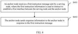
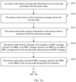
- FIG 4 is a flowchart of an interface establishing method according to this example.
- An entity for implementing this example may be an anchor node. As shown in FIG 4 , the method includes the following steps.
- Step S401 The anchor node receives a first instruction message sent by a serving node, where the first instruction information is used to instruct to establish a first interface between the serving node and the anchor node.
- the first interface includes at least a control plane interface between the serving node and the anchor node, the control plane interface is at least used to transmit an RRC message of a user terminal, an interface connection is established between the anchor node and an MME, and an air interface connection is established between the serving node and the user terminal, the RRC message carried in an SRB1 or an SRB2 in the RRC message of the user terminal is served by the anchor node, and the RRC message carried in an SRB0 of the user terminal is served by the serving node.
- the first interface is an X2 interface or an X3 interface.
- the X2 interface is an interface between one base station and another, and implements interconnection between base stations eNBs.
- the X2 interface is divided into an X2 user plane and an X2 control plane.
- the user plane of the X2 interface provides user data transmission function between the eNBs.
- an S1-C control plane is established between the anchor node and the MME of a core network
- an S1-U user plane interface is established between the anchor node and a serving gateway (SGW).
- SGW serving gateway
- An SRB1 RRC is an RRC message of the UE at a moment of connection establishment completion
- an SRB2 RRC is an RRC message of the UE after connection establishment completion.
- a radio resource control (Radio Resource Control, RRC) function is to split a function of processing RRC messages in the SRBO, the SRB1, and the SRB2 onto two nodes.
- the SRB0 is processed by the serving node, and SRB1 and SRB2 are processed by the anchor node.
- the two nodes are connected through an interface, preferably, an X2 interface.
- the method before the receiving, by the anchor node, a first instruction message sent by a serving node, the method further includes: obtaining, by the anchor node, serving node information of a serving node associated with the anchor node.
- the obtaining, by the anchor node, serving node information of a serving node associated with the anchor node specifically includes:
- Step S402 The anchor node sends response information to the anchor node in response to the first instruction message.
- the anchor node is a base station, or the anchor node is a centralized controller or a control plane server.
- the serving node is a radio transceiver function entity with a scheduling capability, for example, an eNodeB eNB in a Long Term Evolution (Long Term Evolution, LTE) system.
- eNodeB eNB Long Term Evolution (Long Term Evolution, LTE) system.
- the anchor node information includes at least an identifier of the anchor node, preferably, an eNodeB identifier eNB ID.
- the first interface X2 interface is not used for conventional communication between two base stations that are in a parallel relationship, but is used for communication between two base stations that are in a master-slave relationship. That is, a majority of SRB1s and SRB2s of the user terminal (User Equipment, UE) terminate at the anchor node, and a minority terminate at the serving node.
- UE User Equipment
- steps S401 and S402 may be replaced with the following optional solutions.
- the anchor node sends first instruction information to the serving node, and the anchor node receives response information sent by the serving node in response to the first instruction information, where the first instruction information is used to instruct to establish a first interface.
- the anchor node receives, through the first interface, the RRC message carried in the SRB1 or the RRC message carried in the SRB2 in an uplink RRC message sent by the serving node, and processes the RRC message, where the uplink RRC message is received by the serving node from the user terminal, and the uplink RRC message includes: the RRC message carried in the SRBO, the RRC message carried in the SRB 1, or the RRC message carried in the SRB2; and/or the anchor node sends a downlink RRC message carried in the SRB1 or the SRB2 to the serving node through the first interface, so that the serving node sends the downlink RRC message carried in the SRB1 or the SRB2 to the user terminal through the air interface connection, where the downlink RRC message includes: the RRC message carried in the SRB1 or the RRC message carried in the SRB2.
- the serving node has a function of the SRB0, and primarily processes a system broadcast message served by a BCCH, a cell paging message served by a PCCH, and optionally RRC messages served by a CCCH in a radio resource control (Radio Resource Control, RRC) connection establishment process and an RRC connection re-establishment process of the UE.
- the serving node has an exclusive RRC protocol entity, configured to generate and send a system broadcast message, and send, to the anchor node, a system broadcast message of a serving cell to which the serving node belongs.
- the system broadcast message may be a MIB, a SIB, a paging message, or MBMS control information.
- a protocol stack of the serving node includes an RLC protocol entity corresponding to a DRB, an SRB1, and an SRB2 of the UE, and a MAC protocol entity and a physical layer (Physical Layer, PHY) protocol entity that are corresponding to the UE.
- the anchor node sends a first TAC that needs to be supported by the serving node to the serving node, or the anchor node receives a second TAC supported by the serving node and indicated by the serving node; and the anchor node receives, through the interface established between the anchor node and the MME, a paging message sent by the MME.
- the anchor node When the first TAC or the second TAC is included in the paging message, sending, by the anchor node, the paging message to the serving node through the first interface.
- the TAC is a tracking area code (TA code, TAC).
- the response information in establishing the first interface includes the first TAC that needs to be supported by the serving node, or the first instruction message includes the second TAC that can be supported by the serving node.
- a code of a serving cell of the serving node that is sent by the serving node is received, where the code of the serving cell is used by the anchor node to use the serving cell as a serving cell, and is sent to a neighboring anchor node or a neighboring base station.
- the anchor node uses the serving cell as a local serving cell, and forwards the system broadcast message to the neighboring anchor node or the neighboring base station of the anchor node, so as to receive a request message from the neighboring anchor node or the neighboring eNB in the future.
- the anchor node receives a Non-UE Associated message sent by the MME, and the anchor node sends the Non-UE Associated message to the serving node through the control plane interface between the serving node and the anchor node.
- the RRC protocol entity of the serving node processes the messages.
- an anchor node receives a first instruction message sent by a serving node; and the anchor node sends response information to the anchor node in response to the first instruction message.
- a first interface between the serving node and the anchor node is established according to the first instruction information, so that a radio connection is established between the serving node and the anchor node through the established first interface.
- the serving node serves an RRC message carried in an SRB0 of a user terminal
- the anchor node serves an RRC message carried in an SRB1 or an SRB2 of the user terminal.
- a radio connection between the terminal and the serving node can terminate at the anchor node, and when the terminal changes the serving node of a same anchor node, an interface of the terminal does not need to be changed, thereby reducing signaling load of a core network caused by handover.
- FIG 5A and FIG 5B are a detailed flowchart of an interface establishing method according to this example.
- An entity for implementing this example may be an anchor node.
- the method includes the following steps.
- Step S501 The anchor node obtains serving node information of the serving node associated with the anchor node.
- That the anchor node obtains serving node information of a serving node associated with the anchor node specifically includes: obtaining, by the anchor node, the serving node information by means of an OAM; or when the serving node information is configured on the anchor node, obtaining the configured serving node information of the serving node associated with the anchor node.
- Step S502 The anchor node receives a first instruction message sent by the serving node.
- the anchor node is a base station, or the anchor node is a centralized controller or a control plane server.
- the first instruction information is used to instruct to establish a first interface between the serving node and the anchor node.
- Step S503 The anchor node sends response information to the anchor node in response to the first instruction message.
- the first interface includes at least a control plane interface between the serving node and the anchor node, the control plane interface is at least used to transmit an RRC message of a user terminal, an interface connection is established between the anchor node and an MME, and an air interface connection is established between the serving node and the user terminal, the RRC message carried in an SRB1 or an SRB2 in the RRC message of the user terminal is served by the anchor node, and the RRC message carried in an SRB0 of the user terminal is served by the serving node.
- the interface for establishing the interface connection between the anchor node and the MME is specifically an S1-MME interface.
- steps S502 and S503 may be replaced with the following optional solutions.
- the anchor node sends first instruction information to the serving node, and the anchor node receives response information sent by the serving node in response to the first instruction information, where the first instruction information is used to instruct to establish a first interface.
- Step S504 The anchor node receives, through the first interface, an RRC message carried in an SRB1 or an RRC message carried in an SRB2 in an uplink RRC message sent by the serving node, and processes the RRC message.
- the uplink RRC message is received by the serving node from the user terminal, and the uplink RRC message includes: the RRC message carried in an SRBO, the RRC message carried in the SRB1, or the RRC message carried in the SRB2.
- Step S505 The anchor node sends a downlink RRC message carried in the SRB1 or the SRB2 to the serving node through the first interface.
- the serving node sends the downlink RRC message carried in the SRB1 or the SRB2 to the user terminal through the air interface connection.
- the downlink RRC message includes: the RRC message carried in the SRB1 or the RRC message carried in the SRB2.
- step S504 there is no definite order between step S504 and step S505, that is, step S504 may be performed before step S505, or either step S504 or step S505 may be performed.
- Step S506 The anchor node sends a first TAC that needs to be supported by the serving node to the serving node.
- the anchor node receives a second TAC supported by the serving node and indicated by the serving node.
- Step S507 The anchor node receives, through an interface established between the anchor node and the MME, a paging message sent by the MME.
- the paging message is received by the anchor node from the MME through the S1-MME interface.
- Step S508 When the first TAC or the second TAC is included in the paging message, the anchor node sends the paging message to the serving node through the first interface.
- Step S509 Receive a code of a serving cell of the serving node that is sent by the serving node.
- the code of the serving cell is used by the anchor node to use the serving cell as a serving cell, and is sent to a neighboring anchor node or a neighboring base station.
- Step S510 The anchor node receives a Non-UE Associated message sent by the MME, and the anchor node sends the Non-UE Associated message to the serving node through the control plane interface between the serving node and the anchor node.
- an anchor node receives a first instruction message sent by a serving node; and the anchor node sends response information to the anchor node in response to the first instruction message.
- a first interface between the serving node and the anchor node is established according to the first instruction information, so that a radio connection is established between the serving node and the anchor node through the established first interface.
- the serving node serves an RRC message carried in an SRB0 of a user terminal
- the anchor node serves an RRC message carried in an SRB1 or an SRB2 of the user terminal.
- a radio connection between the terminal and the serving node can terminate at the anchor node, and when the terminal changes the serving node of a same anchor node, an interface of the terminal does not need to be changed, thereby reducing signaling load of a core network caused by handover.
- the anchor node receives a paging message sent by an MME, and a first TAC or a second TAC is included in the paging message
- the serving node directly receives the paging message sent by the anchor node, thereby reducing a quantity of paging messages and further reducing the signaling load of the core network.
- FIG 6A and FIG 6B are a signaling diagram of an interface establishing method according to an example not forming part of the invention. As shown in FIG 6A and FIG 6B , the following elaborates on a signaling interworking process of an interface establishing method provided in this example. The method includes the following steps.
- Step S601 A serving node obtains anchor node information of an anchor node associated with the serving node.
- the serving node configures, by means of an OAM, the anchor node information of the anchor node associated with the serving node; or the serving node obtains the anchor node information by means of a downlink signal of a base station, where the downlink signal includes a synchronization signal and system information; or when the anchor node information is configured on the serving node, the serving node obtains the configured anchor node information of the anchor node associated with the serving node.
- Step S602 The serving node sends first instruction information to the anchor node.
- the first instruction information is used to instruct to establish a first interface.
- the first interface includes at least a control plane interface between the serving node and the anchor node, the control plane interface is at least used to transmit an RRC message of a user terminal, an S1-MME interface connection is established between the anchor node and an MME, and an air interface connection is established between the serving node and the user terminal, the RRC message corresponding to an SRB1 or an SRB2 in the RRC message of the user terminal is served by the anchor node, and the RRC message corresponding to an SRB0 of the user terminal is served by the serving node.
- Step S603 The serving node receives response information sent by the anchor node in response to the first instruction information.
- Step S604 The serving node receives an uplink RRC message sent by a user terminal.
- the uplink RRC message includes: the RRC message carried in the SRBO, the RRC message carried in the SRB1, or the RRC message carried in the SRB2.
- Step S605 The serving node processes an SRB0 in the uplink RRC message.
- Step S606 The serving node sends, through the first interface, an RRC message carried in an SRB1 or an RRC message carried in an SRB2 in the uplink RRC message to the anchor node for processing.
- Step S607 The anchor node receives, through the first interface, the RRC message carried in the SRB1 or the RRC message carried in the SRB2 in the uplink RRC message, and processes the RRC message.
- Step S608 The serving node generates a downlink RRC message carried in the SRB0.
- Step S609 The serving node sends the generated downlink RRC message carried in the SRB0 to the user terminal through the air interface connection.
- Step S610 The anchor node sends a downlink RRC message carried in the SRB1 or the SRB2 to the serving node through the first interface.
- Step S611 The serving node receives, through the first interface, the downlink RRC message carried in the SRB1 or the SRB2 and sent by the anchor node, and the serving node sends the downlink RRC message carried in the SRB1 or the SRB2 to the user terminal through the air interface connection.
- Step S612 The anchor node sends a first tracking area code TAC that needs to be supported by the serving node to the serving node.
- the serving node indicates a second TAC that can be supported by the serving node to the anchor node.
- Step S613 The anchor node receives, through the S1-MME interface, a paging message sent by an MME.
- Step S614 The serving node receives the paging message sent by the anchor node through the first interface.
- the paging message is received by the anchor node from the MME through the S1-MME interface, and the first TAC or the second TAC is included in the paging message sent by the MME.
- Step S615 The serving node sends a code of a serving cell of the serving node to the anchor node.
- Step S616 The anchor node receives the code of the serving cell of the serving node that is sent by the serving node, and the anchor node uses the serving cell as a serving cell, and sends the code of the serving cell to a neighboring anchor node or a neighboring base station.
- Step S617 The anchor node receives a Non-UE Associated message sent by the MME.
- Step S618 The anchor node sends the Non-UE Associated message to the serving node through the control plane interface.
- Step S619 The serving node sends the paging message or the Non-UE Associated message to the user terminal.
- an anchor node receives a first instruction message sent by a serving node; and the anchor node sends response information to the anchor node in response to the first instruction message.
- a first interface between the serving node and the anchor node is established according to the first instruction information, so that a radio connection is established between the serving node and the anchor node through the established first interface.
- the serving node serves an RRC message carried in an SRB0 of a user terminal
- the anchor node serves an RRC message carried in an SRB 1 or an SRB2 of the user terminal.
- a radio connection between the terminal and the serving node can terminate at the anchor node, and when the terminal changes the serving node of a same anchor node, an interface of the terminal does not need to be changed, thereby reducing signaling load of a core network caused by handover.
- the anchor node receives a paging message sent by an MME, and a first TAC or a second TAC is included in the paging message
- the serving node directly receives the paging message sent by the anchor node, thereby reducing a quantity of paging messages and further reducing the signaling load of the core network.
- Example 1 describes an interface establishing method implemented by a serving node.
- this embodiment of the present invention further provides an interface establishing apparatus.
- FIG 7 is a schematic diagram of an interface establishing apparatus according to this embodiment of the present invention. As shown in FIG 7 , the interface establishing apparatus includes: a sending unit 701 and a receiving unit 702.
- the sending unit 701 is configured to send first instruction information to an anchor node, where the first instruction information is used to instruct to establish a first interface between a serving node and the anchor node.
- the receiving unit 702 is configured to receive response information sent by the anchor node in response to the first instruction information.
- the receiving unit 702 is further configured to receive first instruction information sent by an anchor node, where the first instruction information is used to instruct to establish a first interface; and the sending unit 701 is further configured to send response information to the anchor node in response to the first instruction information.
- the first interface includes at least a control plane interface between the serving node and the anchor node, the control plane interface is at least used to transmit a radio resource control RRC message of a user terminal, an interface connection is established between the anchor node and a mobility management entity MME, and an air interface connection is established between the apparatus and the user terminal, the RRC message carried in a signaling radio bearer 1 SRB1 or a signaling radio bearer 2 SRB2 in the RRC message of the user terminal is served by the anchor node, and the RRC message carried in a signaling radio bearer 0 SRB0 of the user terminal is served by the serving node.
- the control plane interface is at least used to transmit a radio resource control RRC message of a user terminal
- an interface connection is established between the anchor node and a mobility management entity MME
- an air interface connection is established between the apparatus and the user terminal
- the apparatus further includes a processing unit;
- the apparatus further includes: an obtaining unit 703, configured to obtain anchor node information of an anchor node associated with the serving node.
- the obtaining unit 703 is specifically configured to:
- the interface for establishing the interface connection between the anchor node and the MME is specifically an S1-MME interface.
- the anchor node is a base station, or the anchor node is a centralized controller or a control plane server.
- the receiving unit 702 is further configured to receive a first tracking area code TAC that is sent by the anchor node and that needs to be supported, or the sending unit is further configured to indicate a second TAC supported by the serving node to the anchor node; and the receiving unit 702 is further configured to receive a paging message sent by the anchor node through the first interface, where the paging message is received by the anchor node from the MME through the interface established between the anchor node and the mobility management entity, and the first TAC or the second TAC is included in the paging message sent by the MME.
- TAC tracking area code
- the sending unit 701 is further configured to send a code of a serving cell of the serving node to the anchor node, where the code of the serving cell is used by the anchor node to use the serving cell as a serving cell of the anchor node, and is sent to a neighboring anchor node or a neighboring base station of the anchor node.
- the receiving unit 702 is further configured to receive, through the control plane interface between the serving node and the anchor node, a non-UE associated message sent by the anchor node, where the Non-UE Associated message is received by the anchor node from the MME.
- the apparatus is located in the serving node.
- a serving node sends first instruction information to an anchor node; and the serving node receives response information sent by the anchor node in response to the first instruction information.
- a first interface between the serving node and the anchor node is established according to the first instruction information, so that a radio connection is established between the serving node and the anchor node through the established first interface.
- the serving node serves an RRC message carried in an SRB0 of a user terminal
- the anchor node serves an RRC message carried in an SRB 1 or an SRB2 of the user terminal.
- a radio connection between the terminal and the serving node can terminate at the anchor node, and when the terminal changes the serving node of a same anchor node, an interface of the terminal does not need to be changed, thereby reducing signaling load of a core network caused by handover.
- Embodiment 3 describes an interface establishing method implemented by an anchor node.
- this embodiment of the present invention further provides an interface establishing apparatus.
- FIG 8 is a schematic diagram of an interface establishing apparatus according to this example. As shown in FIG 8 , the interface establishing apparatus includes: a receiving unit 801 and a sending unit 802.
- the receiving unit 801 is configured to receive a first instruction message sent by a serving node, where the first instruction information is used to instruct to establish a first interface between the serving node and an anchor node.
- the sending unit 802 is configured to send response information to the apparatus in response to the first instruction message.
- the sending unit 802 is further configured to send first instruction information to the serving node, where the first instruction information is used to instruct to establish a first interface.
- the receiving unit 801 is further configured to receive response information sent by the serving node in response to the first instruction information.
- the first interface includes at least a control plane interface between the serving node and the anchor node, the control plane interface is at least used to transmit an RRC message of a user terminal, an interface connection is established between the apparatus and an MME, and an air interface connection is established between the serving node and the user terminal, the RRC message carried in an SRB1 or an SRB2 in the RRC message of the user terminal is served by the anchor node, and the RRC message carried in an SRB0 of the user terminal is served by the serving node.
- the receiving unit 801 is further configured to receive, through the first interface, the RRC message carried in the SRB1 or the RRC message carried in the SRB2 in an uplink RRC message sent by the serving node, and process the RRC message, where the uplink RRC message is received by the serving node from the user terminal, and the uplink RRC message includes: the RRC message carried in the SRBO, the RRC message carried in the SRB1, or the RRC message carried in the SRB2; and/or the sending unit 802 is further configured to send a downlink RRC message carried in the SRB1 or the SRB2 to the serving node through the first interface, so that the serving node sends the downlink RRC message carried in the SRB1 or the SRB2 to the user terminal through the air interface connection, where the downlink RRC message includes: the RRC message carried in the SRB1 or the RRC message carried in the SRB2.
- the apparatus further includes: an obtaining unit 803, configured to obtain serving node information of a serving node associated with the anchor node.
- the interface for establishing the interface connection between the anchor node and the MME is specifically an S1-MME interface.
- the obtaining unit 803 is specifically configured to:
- the sending unit 802 is further configured to send a first TAC that needs to be supported by the serving node to the serving node, or the receiving unit is further configured to receive a second TAC supported by the serving node and indicated by the serving node;
- the apparatus is a base station, or is a centralized controller or a control plane server.
- the receiving unit 801 is further configured to receive a code of a serving cell of the serving node that is sent by the serving node, where the code of the serving cell is used by the anchor node to use the serving cell as a serving cell, and is sent to a neighboring anchor node or a neighboring base station.
- the receiving unit 801 is further configured to receive a Non-UE Associated message sent by the MME, and send the Non-UE Associated message to the serving node through the control plane interface between the serving node and the anchor node.
- the apparatus is located in the anchor node.
- an anchor node receives a first instruction message sent by a serving node; and the anchor node sends response information to the anchor node in response to the first instruction message.
- a first interface between the serving node and the anchor node is established according to the first instruction information, so that a radio connection is established between the serving node and the anchor node through the established first interface.
- the serving node serves an RRC message carried in an SRB0 of a user terminal
- the anchor node serves an RRC message carried in an SRB1 or an SRB2 of the user terminal.
- a radio connection between the terminal and the serving node can terminate at the anchor node, and when the terminal changes the serving node of a same anchor node, an interface of the terminal does not need to be changed, thereby reducing signaling load of a core network caused by handover.
- Example 1 describes an interface establishing method implemented by a serving node.
- this embodiment of the present invention further provides an interface establishing apparatus to implement the interface establishing method in Embodiment 1.
- FIG 9 is a schematic diagram of an interface establishing apparatus according to this embodiment of the present invention.
- the interface establishing apparatus includes: a network interface 901, a processor 902, and a memory 903.
- a system bus 904 is configured to connect the network interface 901, the processor 902, and the memory 903.
- the network interface 901 is configured to communicate with a terminal of the Internet of Things, an access gateway of the Internet of Things, a bearer network, a serving gateway of the Internet of Things, and an application server.
- the memory 903 may be a permanent memory, such as a hard disk drive and a flash memory.
- a software module and a device driver exist in the memory 903.
- the software module may be any type of function module capable of implementing the foregoing method of the present invention, and the device driver may be a network and interface driver.
- a serving node sends first instruction information to an anchor node; and the serving node receives response information sent by the anchor node in response to the first instruction information.
- a first interface between the serving node and the anchor node is established according to the first instruction information, so that a radio connection is established between the serving node and the anchor node through the established first interface.
- the serving node serves an RRC message carried in an SRB0 of a user terminal
- the anchor node serves an RRC message carried in an SRB 1 or an SRB2 of the user terminal.
- a radio connection between the terminal and the serving node can terminate at the anchor node, and when the terminal changes the serving node of a same anchor node, an interface of the terminal does not need to be changed, thereby reducing signaling load of a core network caused by handover.
- FIG 10 is a schematic diagram of an interface establishing apparatus according to an example not forming part of the invention.
- the interface establishing apparatus includes: a network interface 1001, a processor 1002, and a memory 1003.
- a system bus 1004 is configured to connect the network interface 1001, the processor 1002, and the memory 1003.
- the network interface 1001 is configured to communicate with a terminal of the Internet of Things, an access gateway of the Internet of Things, a bearer network, a serving gateway of the Internet of Things, and an application server.
- the memory 1003 may be a permanent memory, such as a hard disk drive and a flash memory.
- a software module and a device driver exist in the memory 1003.
- the software module may be any type of function module capable of implementing the foregoing method of the present invention, and the device driver may be a network and interface driver.
- Steps of methods or algorithms described in the embodiments disclosed in this specification may be implemented by hardware, a software module executed by a processor, or a combination thereof.
- the software module may reside in a random access memory (RAM), a memory, a read-only memory (ROM), an electrically programmable ROM, an electrically erasable programmable ROM, a register, a hard disk, a removable disk, a CD-ROM, or any other form of storage medium known in the art.
Landscapes
- Engineering & Computer Science (AREA)
- Computer Networks & Wireless Communication (AREA)
- Signal Processing (AREA)
- Mobile Radio Communication Systems (AREA)
- Communication Control (AREA)
Claims (11)
- Verfahren zum Herstellen einer Schnittstelle und zur Kommunikation, wobei das Verfahren Folgendes umfasst:• Senden, durch einen bedienenden Knoten, von Befehlsinformationen an einen Ankerknoten, wobei die Befehlsinformationen verwendet werden, um zu befehlen, eine erste Schnittstelle zwischen dem bedienenden Knoten und dem Ankerknoten herzustellen, wobei die erste Schnittstelle eine Schnittstelle der Steuerungsebene umfasst und die Schnittstelle der Steuerungsebene verwendet wird, um eine Funkressourcensteuerungsnachricht eines Benutzerendgeräts zu übertragen (S 302);• Empfangen, durch den bedienenden Knoten, von Antwortinformationen aus dem Ankerknoten als Reaktion auf die Befehlsinformationen (S 303);wobei bei einer ersten Alternative das Verfahren weiterhin die folgenden Schritte umfasst:∘ Empfangen, durch den bedienenden Knoten, einer Aufwärtsstrecken-Ressourcensteuerungsnachricht, RRC-Nachricht, die in einem Signalisierungsfunkträger, SRB0, getragen wird, aus dem Benutzerendgerät;∘ Verarbeiten, durch den bedienenden Knoten, der Aufwärtsstrecken-Ressourcensteuerungsnachricht, die in dem SRB0 getragen wird (S 304);∘ Empfangen, durch den bedienenden Knoten, einer Aufwärtsstrecken-RRC-Nachricht, die in einem SRB1 getragen wird, aus dem Benutzerendgerät;∘ Senden, durch den bedienenden Knoten über die erste Schnittstelle, der Aufwärtsstrecken-RRC-Nachricht, die in dem SRB1 getragen wird, an den Ankerknoten zum Verarbeiten (S 305);oder, bei einer zweiten Alternative an Stelle der ersten Alternative, das Verfahren weiterhin die folgenden Schritte umfasst:∘ Erzeugen, durch den bedienenden Knoten, einer Abwärtsstrecken-RRC-Nachricht, die in dem SRB0 getragen wird;∘ Senden, durch den bedienenden Knoten, der erzeugten Abwärtsstrecken-RRC-Nachricht in dem SRB0 an das Benutzerendgerät (S 306);∘ Empfangen, durch den bedienenden Knoten, einer Abwärtsstrecken-RRC-Nachricht, die in dem SRB1 getragen wird, durch die erste Schnittstelle aus dem Ankerknoten;∘ Senden, durch den bedienenden Knoten, der Abwärtsstrecken-RRC-Nachricht, die in dem SRB1 getragen wird, an das Benutzerendgerät (S 307).
- Verfahren nach Anspruch 1, wobei eine Luftschnittstellenverbindung zwischen dem bedienenden Knoten und dem Benutzerendgerät hergestellt wird.
- Verfahren nach einem der Ansprüche 1 bis 2, wobei das Verfahren vor dem Senden, durch den bedienenden Knoten, der Befehlsinformationen an den Ankerknoten, weiterhin Folgendes umfasst:
Erlangen, durch den bedienenden Knoten, von Ankerknoteninformationen des Ankerknotens, der dem bedienenden Knoten zugeordnet ist. - Verfahren nach einem der Ansprüche 1 bis 3, wobei das Verfahren weiterhin Folgendes umfasst:Angeben, durch den bedienenden Knoten, eines Zielverfolgungsbereichscodes, TAC, der von dem bedienenden Knoten unterstützt wird, an den Ankerknoten; undEmpfangen, durch den bedienenden Knoten, einer Funkrufnachricht aus einer Mobilitätsmanagemententität über die erste Schnittstelle, wobei der TAC in der Funkrufnachricht enthalten ist und die Mobilitätsmanagemententität mit dem Ankerknoten verbunden ist.
- Verfahren nach einem der Ansprüche 1 bis 4, wobei der Ankerknoten eine zentrale Steuervorrichtung ist.
- Verfahren nach einem der Ansprüche 1 bis 5, wobei das Verfahren weiterhin Folgendes umfasst:
Senden, durch den bedienenden Knoten, eines Codes einer bedienenden Zelle des bedienenden Knotens an den Ankerknoten, wobei der Code der bedienenden Zelle verwendet wird, um die bedienende Zelle als eine bedienende Zelle des Ankerknotens zu verwenden, und an eine benachbarte Basisstation des Ankerknotens gesendet wird. - Verfahren nach einem der Ansprüche 1 bis 6, wobei das Verfahren weiterhin Folgendes umfasst:
Empfangen, durch den bedienenden Knoten über die Schnittstelle der Steuerungsebene, einer keinem UE zugeordneten Nachricht aus dem Ankerknoten, wobei die keinem UE zugeordnete Nachricht aus einer Mobilitätsmanagemententität stammt, die mit dem Ankerknoten verbunden ist. - Verfahren nach einem der Ansprüche 1 bis 7, wobei das Verfahren weiterhin Folgendes umfasst:Empfangen, durch den Ankerknoten, eines Zielverfolgungsbereichscodes, TAC, der von dem bedienenden Knoten unterstützt wird und durch den bedienenden Knoten gesendet wird;Empfangen, durch den Ankerknoten über eine Schnittstelle, die zwischen dem Ankerknoten und einer Mobilitätsmanagemententität hergestellt wurde, einer Funkrufnachricht aus der Mobilitätsmanagemententität; undwenn der TAC in der Funkrufnachricht enthalten ist, Senden der Funkrufnachricht durch den Ankerknoten über die erste Schnittstelle an den bedienenden Knoten.
- Bedienender Knoten, der eingerichtet ist, um eines der Verfahren nach den Ansprüchen 1 bis 7 durchzuführen.
- Computerlesbares Speichermedium, umfassend Befehle, die, wenn sie von einem Prozessor auf einem bedienenden Knoten ausgeführt werden, bewirken, dass der bedienende Knoten einen der Verfahrensschritte der Ansprüche 1 bis 7 ausführt.
- Kommunikationssystem, umfassend einen bedienenden Knoten und einen Ankerknoten, wobei der bedienende Knoten eingerichtet ist, um:• Befehlsinformationen an den Ankerknoten zu senden, wobei die Befehlsinformationen verwendet werden, um zu befehlen, eine erste Schnittstelle zwischen dem bedienenden Knoten und dem Ankerknoten herzustellen, wobei die erste Schnittstelle eine Schnittstelle der Steuerungsebene umfasst und die Schnittstelle der Steuerungsebene verwendet wird, um eine Funkressourcensteuerungsnachricht eines Benutzerendgeräts zu übertragen (S 302);• Antwortinformationen aus dem Ankerknoten als Reaktion auf die Befehlsinformationen zu empfangen (S 303);wobei bei einer ersten Alternative der bedienende Knoten weiterhin eingerichtet ist, um:∘ eine Aufwärtsstrecken-Ressourcensteuerungsnachricht, RRC-Nachricht, die in einem Signalisierungsfunkträger, SRB0, getragen wird, aus dem Benutzerendgerät zu empfangen;∘ die Aufwärtsstrecken-Ressourcensteuerungsnachricht zu verarbeiten, die in dem SRB0 getragen wird (S 304);∘ eine Aufwärtsstrecken-RRC-Nachricht, die in einem SRB1 getragen wird, aus dem Benutzerendgerät zu empfangen;∘ die Aufwärtsstrecken-RRC-Nachricht, die in dem SRB1 getragen wird, über die erste Schnittstelle an den Ankerknoten zum Verarbeiten zu senden (S 305);oder, bei einer zweiten Alternative an Stelle der ersten Alternative, der bedienende Knoten weiterhin eingerichtet ist, um:∘ eine Abwärtsstrecken-RRC-Nachricht zu erzeugen, die in dem SRB0 getragen wird;∘ die erzeugte Abwärtsstrecken-RRC-Nachricht in dem SRB0 an das Benutzerendgerät zu senden (S 306);∘ eine Abwärtsstrecken-RRC-Nachricht, die in dem SRB1 getragen wird, durch die erste Schnittstelle aus dem Ankerknoten zu empfangen;∘ die Abwärtsstrecken-RRC-Nachricht, die in dem SRB1 getragen wird, an das Benutzerendgerät zu senden (S 307);wobei der Ankerknoten eingerichtet ist, um:• die Befehlsinformationen zu empfangen und die Antwortinformationen zu senden;wobei bei einer ersten Alternative der Ankerknoten weiterhin eingerichtet ist, um:∘ die Aufwärtsstrecken-RRC-Nachricht zu empfangen, die in dem SRB1 getragen wird;oder, bei einer zweiten Alternative an Stelle der ersten Alternative, der bedienende Knoten weiterhin eingerichtet ist, um:∘ die Abwärtsstrecken-RRC-Nachricht, die in dem SRB1 getragen wird, über die erste Schnittstelle zu senden.
Priority Applications (1)
| Application Number | Priority Date | Filing Date | Title |
|---|---|---|---|
| EP19204468.3A EP3700295B1 (de) | 2014-10-23 | 2014-10-23 | Verfahren und vorrichtung zur herstellung einer schnittstelle |
Applications Claiming Priority (3)
| Application Number | Priority Date | Filing Date | Title |
|---|---|---|---|
| EP14904498.4A EP3203801B1 (de) | 2014-10-23 | 2014-10-23 | Verfahren und vorrichtung zur erstellung einer schnittstelle um rrc split funktion zu stützen |
| PCT/CN2014/089310 WO2016061791A1 (zh) | 2014-10-23 | 2014-10-23 | 接口建立方法及装置 |
| EP19204468.3A EP3700295B1 (de) | 2014-10-23 | 2014-10-23 | Verfahren und vorrichtung zur herstellung einer schnittstelle |
Related Parent Applications (2)
| Application Number | Title | Priority Date | Filing Date |
|---|---|---|---|
| EP14904498.4A Division EP3203801B1 (de) | 2014-10-23 | 2014-10-23 | Verfahren und vorrichtung zur erstellung einer schnittstelle um rrc split funktion zu stützen |
| EP14904498.4A Division-Into EP3203801B1 (de) | 2014-10-23 | 2014-10-23 | Verfahren und vorrichtung zur erstellung einer schnittstelle um rrc split funktion zu stützen |
Publications (2)
| Publication Number | Publication Date |
|---|---|
| EP3700295A1 EP3700295A1 (de) | 2020-08-26 |
| EP3700295B1 true EP3700295B1 (de) | 2024-10-23 |
Family
ID=55760079
Family Applications (2)
| Application Number | Title | Priority Date | Filing Date |
|---|---|---|---|
| EP14904498.4A Active EP3203801B1 (de) | 2014-10-23 | 2014-10-23 | Verfahren und vorrichtung zur erstellung einer schnittstelle um rrc split funktion zu stützen |
| EP19204468.3A Active EP3700295B1 (de) | 2014-10-23 | 2014-10-23 | Verfahren und vorrichtung zur herstellung einer schnittstelle |
Family Applications Before (1)
| Application Number | Title | Priority Date | Filing Date |
|---|---|---|---|
| EP14904498.4A Active EP3203801B1 (de) | 2014-10-23 | 2014-10-23 | Verfahren und vorrichtung zur erstellung einer schnittstelle um rrc split funktion zu stützen |
Country Status (9)
| Country | Link |
|---|---|
| US (2) | US10728876B2 (de) |
| EP (2) | EP3203801B1 (de) |
| JP (1) | JP2017531970A (de) |
| KR (1) | KR102015445B1 (de) |
| CN (2) | CN105766052B9 (de) |
| BR (1) | BR112017008258B1 (de) |
| ES (1) | ES2773885T3 (de) |
| RU (1) | RU2665210C1 (de) |
| WO (1) | WO2016061791A1 (de) |
Families Citing this family (5)
| Publication number | Priority date | Publication date | Assignee | Title |
|---|---|---|---|---|
| CN104581816A (zh) * | 2014-12-18 | 2015-04-29 | 上海华为技术有限公司 | 一种数据多流传输方法、装置、锚点及系统 |
| US10130367B2 (en) | 2015-02-26 | 2018-11-20 | Covidien Lp | Surgical apparatus |
| CN109246844B (zh) * | 2017-06-16 | 2022-07-15 | 中兴通讯股份有限公司 | 无线承载的配置方法及系统 |
| WO2019153295A1 (zh) * | 2018-02-11 | 2019-08-15 | Oppo广东移动通信有限公司 | 移动通信系统、方法及装置 |
| CN111770539B (zh) * | 2019-04-02 | 2021-07-09 | 大唐移动通信设备有限公司 | 一种lmf选择方法、终端定位服务方法及装置 |
Family Cites Families (24)
| Publication number | Priority date | Publication date | Assignee | Title |
|---|---|---|---|---|
| US20060018280A1 (en) * | 2004-07-20 | 2006-01-26 | Nokia Corporation | System and associated mobile node, foreign agent and method for link-layer assisted mobile IP fast handoff from a fast-access network to a slow-access network |
| CN1801759A (zh) * | 2005-10-31 | 2006-07-12 | 华为技术有限公司 | 加快终端切换的方法 |
| KR101782759B1 (ko) * | 2008-02-01 | 2017-09-27 | 옵티스 와이어리스 테크놀로지, 엘엘씨 | 통신 단말기 및 우선순위가 매겨진 제어 정보를 사용하는 방법 |
| US9549389B2 (en) * | 2008-05-07 | 2017-01-17 | Telefonaktiebolaget Lm Ericsson (Publ) | Methods and arrangements for paging a communication device |
| RU2507715C2 (ru) * | 2008-06-16 | 2014-02-20 | Самсунг Электроникс Ко., Лтд. | Способ и система управления передачей в сетях радиодоступа |
| US8639269B2 (en) | 2008-12-10 | 2014-01-28 | Nec Corporation | Wireless communication system, wireless base station, mobile terminal, wireless communication method, and program |
| JP4875119B2 (ja) * | 2009-04-27 | 2012-02-15 | 株式会社エヌ・ティ・ティ・ドコモ | 移動通信システム |
| JP5462357B2 (ja) * | 2009-04-28 | 2014-04-02 | ▲ホア▼▲ウェイ▼技術有限公司 | ページング方法、ロケーション更新方法、およびデバイス |
| CN102469439A (zh) * | 2010-11-05 | 2012-05-23 | 中兴通讯股份有限公司 | 一种x2接口信息的指示和获取方法及系统 |
| EP2509345A1 (de) * | 2011-04-05 | 2012-10-10 | Panasonic Corporation | Verbesserte Übertragung kleiner Datenmengen für MTC-Vorrichtungen |
| EP2683183A1 (de) * | 2011-04-05 | 2014-01-08 | Panasonic Corporation | Verbesserte Kurznachrichtenübertragung |
| US8434752B2 (en) | 2011-08-05 | 2013-05-07 | Goss International Americas, Inc. | Apparatus for opening and transporting a product with a non-symmetrical fold |
| US20130039287A1 (en) * | 2011-08-12 | 2013-02-14 | Venkata Ratnakar Rao Rayavarapu | Simplified ue + enb messaging |
| CN103988573A (zh) | 2011-12-14 | 2014-08-13 | 日本电气株式会社 | 无线电基站、服务器、移动通信系统和操作控制方法 |
| CN103313233B (zh) | 2012-03-08 | 2017-03-22 | 电信科学技术研究院 | 一种传输网关地址的方法、装置及系统 |
| US9225449B2 (en) * | 2012-05-11 | 2015-12-29 | Intel Corporation | Performing a handover in a heterogeneous wireless network |
| JP6321643B2 (ja) * | 2012-08-02 | 2018-05-09 | テレフオンアクチーボラゲット エルエム エリクソン(パブル) | 複数の基地局に向けての端末の多重的な接続性を可能とする、ベアラのサブセットをハンドオーバさせるためのノード及び方法 |
| EP2888906B1 (de) * | 2012-08-23 | 2021-03-31 | Interdigital Patent Holdings, Inc. | Operationen mit mehrfachterminplanern in einem drahtlosen system |
| JP5878134B2 (ja) * | 2013-01-09 | 2016-03-08 | 株式会社Nttドコモ | 上位基地局、下位基地局、および無線通信システム |
| CN104982088A (zh) * | 2013-01-11 | 2015-10-14 | Lg电子株式会社 | 在无线通信系统中发送指示的方法和装置 |
| US9144091B2 (en) * | 2013-01-17 | 2015-09-22 | Sharp Kabushiki Kaisha | Devices for establishing multiple connections |
| EP2959719B1 (de) * | 2013-02-22 | 2019-06-19 | Telefonaktiebolaget LM Ericsson (publ) | Minimierung einer weiterreichungsunterbrechungszeit im kontext einer s2a-ip-sitzungsmobilität |
| WO2014163082A1 (ja) * | 2013-04-02 | 2014-10-09 | シャープ株式会社 | 無線通信システム、基地局装置、端末装置、無線通信方法および集積回路 |
| US9426709B2 (en) * | 2013-08-08 | 2016-08-23 | Industrial Technology Research Institute | Method of handling anchor-based mobility management |
-
2014
- 2014-10-23 EP EP14904498.4A patent/EP3203801B1/de active Active
- 2014-10-23 KR KR1020177013562A patent/KR102015445B1/ko active Active
- 2014-10-23 RU RU2017117595A patent/RU2665210C1/ru active
- 2014-10-23 EP EP19204468.3A patent/EP3700295B1/de active Active
- 2014-10-23 ES ES14904498T patent/ES2773885T3/es active Active
- 2014-10-23 JP JP2017522346A patent/JP2017531970A/ja active Pending
- 2014-10-23 WO PCT/CN2014/089310 patent/WO2016061791A1/zh not_active Ceased
- 2014-10-23 CN CN201480052936.7A patent/CN105766052B9/zh active Active
- 2014-10-23 CN CN202010246987.0A patent/CN111542127B/zh active Active
- 2014-10-23 BR BR112017008258-6A patent/BR112017008258B1/pt active IP Right Grant
-
2017
- 2017-04-21 US US15/493,628 patent/US10728876B2/en active Active
-
2020
- 2020-07-22 US US16/935,734 patent/US11589331B2/en active Active
Also Published As
| Publication number | Publication date |
|---|---|
| US11589331B2 (en) | 2023-02-21 |
| CN111542127B (zh) | 2023-04-11 |
| RU2665210C1 (ru) | 2018-08-28 |
| EP3203801A1 (de) | 2017-08-09 |
| CN105766052B (zh) | 2020-04-14 |
| US20200351820A1 (en) | 2020-11-05 |
| ES2773885T3 (es) | 2020-07-15 |
| BR112017008258A2 (pt) | 2017-12-26 |
| CN105766052B9 (zh) | 2020-05-19 |
| CN105766052A (zh) | 2016-07-13 |
| US10728876B2 (en) | 2020-07-28 |
| EP3203801B1 (de) | 2019-12-04 |
| BR112017008258B1 (pt) | 2023-03-14 |
| JP2017531970A (ja) | 2017-10-26 |
| KR102015445B1 (ko) | 2019-08-28 |
| EP3700295A1 (de) | 2020-08-26 |
| WO2016061791A1 (zh) | 2016-04-28 |
| EP3203801A4 (de) | 2017-11-29 |
| US20170223751A1 (en) | 2017-08-03 |
| KR20170072283A (ko) | 2017-06-26 |
| CN111542127A (zh) | 2020-08-14 |
Similar Documents
| Publication | Publication Date | Title |
|---|---|---|
| US11076443B2 (en) | Radio resource control RRC message processing method, apparatus, and system | |
| EP3028524B1 (de) | Verfahren und vorrichtungen zur herstellung eines funkträgers | |
| JP7147883B2 (ja) | gNB-CU-UPにおける完全性保護のハンドリング | |
| US11589331B2 (en) | Interface establishing method and apparatus | |
| US20210360712A1 (en) | Radio Resource Control RRC Connection Method and Apparatus and RRC Reconnection Method and Apparatus | |
| US9955513B2 (en) | Radio communication system and control method | |
| WO2016101586A1 (zh) | 一种基站切换方法、系统及相关装置、存储介质 | |
| EP3471462B1 (de) | Verfahren und system zum synchronisierung mit einer zell, die keine systeminformationen sendet | |
| EP3254497B1 (de) | Verfahren und vorrichtungen für dual-connectivity-handover | |
| EP2938155B1 (de) | Verfahren und vorrichtungen zur einrichtung eines trägers |
Legal Events
| Date | Code | Title | Description |
|---|---|---|---|
| PUAI | Public reference made under article 153(3) epc to a published international application that has entered the european phase |
Free format text: ORIGINAL CODE: 0009012 |
|
| STAA | Information on the status of an ep patent application or granted ep patent |
Free format text: STATUS: REQUEST FOR EXAMINATION WAS MADE |
|
| 17P | Request for examination filed |
Effective date: 20191022 |
|
| AC | Divisional application: reference to earlier application |
Ref document number: 3203801 Country of ref document: EP Kind code of ref document: P |
|
| AK | Designated contracting states |
Kind code of ref document: A1 Designated state(s): AL AT BE BG CH CY CZ DE DK EE ES FI FR GB GR HR HU IE IS IT LI LT LU LV MC MK MT NL NO PL PT RO RS SE SI SK SM TR |
|
| RIN1 | Information on inventor provided before grant (corrected) |
Inventor name: REININGER, PHILIPPE Inventor name: LIN, BO |
|
| STAA | Information on the status of an ep patent application or granted ep patent |
Free format text: STATUS: EXAMINATION IS IN PROGRESS |
|
| 17Q | First examination report despatched |
Effective date: 20220126 |
|
| GRAP | Despatch of communication of intention to grant a patent |
Free format text: ORIGINAL CODE: EPIDOSNIGR1 |
|
| STAA | Information on the status of an ep patent application or granted ep patent |
Free format text: STATUS: GRANT OF PATENT IS INTENDED |
|
| RIC1 | Information provided on ipc code assigned before grant |
Ipc: H04W 88/12 20090101ALN20240430BHEP Ipc: H04W 88/08 20090101ALN20240430BHEP Ipc: H04W 92/20 20090101AFI20240430BHEP |
|
| INTG | Intention to grant announced |
Effective date: 20240515 |
|
| GRAS | Grant fee paid |
Free format text: ORIGINAL CODE: EPIDOSNIGR3 |
|
| GRAA | (expected) grant |
Free format text: ORIGINAL CODE: 0009210 |
|
| STAA | Information on the status of an ep patent application or granted ep patent |
Free format text: STATUS: THE PATENT HAS BEEN GRANTED |
|
| AC | Divisional application: reference to earlier application |
Ref document number: 3203801 Country of ref document: EP Kind code of ref document: P |
|
| AK | Designated contracting states |
Kind code of ref document: B1 Designated state(s): AL AT BE BG CH CY CZ DE DK EE ES FI FR GB GR HR HU IE IS IT LI LT LU LV MC MK MT NL NO PL PT RO RS SE SI SK SM TR |
|
| REG | Reference to a national code |
Ref country code: GB Ref legal event code: FG4D |
|
| REG | Reference to a national code |
Ref country code: CH Ref legal event code: EP |
|
| REG | Reference to a national code |
Ref country code: DE Ref legal event code: R096 Ref document number: 602014091072 Country of ref document: DE |
|
| REG | Reference to a national code |
Ref country code: IE Ref legal event code: FG4D |
|
| REG | Reference to a national code |
Ref country code: LT Ref legal event code: MG9D |
|
| REG | Reference to a national code |
Ref country code: NL Ref legal event code: MP Effective date: 20241023 |
|
| REG | Reference to a national code |
Ref country code: AT Ref legal event code: MK05 Ref document number: 1735917 Country of ref document: AT Kind code of ref document: T Effective date: 20241023 |
|
| PG25 | Lapsed in a contracting state [announced via postgrant information from national office to epo] |
Ref country code: NL Free format text: LAPSE BECAUSE OF FAILURE TO SUBMIT A TRANSLATION OF THE DESCRIPTION OR TO PAY THE FEE WITHIN THE PRESCRIBED TIME-LIMIT Effective date: 20241023 |
|
| PG25 | Lapsed in a contracting state [announced via postgrant information from national office to epo] |
Ref country code: NL Free format text: LAPSE BECAUSE OF FAILURE TO SUBMIT A TRANSLATION OF THE DESCRIPTION OR TO PAY THE FEE WITHIN THE PRESCRIBED TIME-LIMIT Effective date: 20241023 |
|
| PG25 | Lapsed in a contracting state [announced via postgrant information from national office to epo] |
Ref country code: IS Free format text: LAPSE BECAUSE OF FAILURE TO SUBMIT A TRANSLATION OF THE DESCRIPTION OR TO PAY THE FEE WITHIN THE PRESCRIBED TIME-LIMIT Effective date: 20250223 Ref country code: HR Free format text: LAPSE BECAUSE OF FAILURE TO SUBMIT A TRANSLATION OF THE DESCRIPTION OR TO PAY THE FEE WITHIN THE PRESCRIBED TIME-LIMIT Effective date: 20241023 Ref country code: PT Free format text: LAPSE BECAUSE OF FAILURE TO SUBMIT A TRANSLATION OF THE DESCRIPTION OR TO PAY THE FEE WITHIN THE PRESCRIBED TIME-LIMIT Effective date: 20250224 |
|
| PG25 | Lapsed in a contracting state [announced via postgrant information from national office to epo] |
Ref country code: FI Free format text: LAPSE BECAUSE OF FAILURE TO SUBMIT A TRANSLATION OF THE DESCRIPTION OR TO PAY THE FEE WITHIN THE PRESCRIBED TIME-LIMIT Effective date: 20241023 |
|
| PG25 | Lapsed in a contracting state [announced via postgrant information from national office to epo] |
Ref country code: BG Free format text: LAPSE BECAUSE OF FAILURE TO SUBMIT A TRANSLATION OF THE DESCRIPTION OR TO PAY THE FEE WITHIN THE PRESCRIBED TIME-LIMIT Effective date: 20241023 |
|
| PG25 | Lapsed in a contracting state [announced via postgrant information from national office to epo] |
Ref country code: ES Free format text: LAPSE BECAUSE OF FAILURE TO SUBMIT A TRANSLATION OF THE DESCRIPTION OR TO PAY THE FEE WITHIN THE PRESCRIBED TIME-LIMIT Effective date: 20241023 |
|
| PG25 | Lapsed in a contracting state [announced via postgrant information from national office to epo] |
Ref country code: NO Free format text: LAPSE BECAUSE OF FAILURE TO SUBMIT A TRANSLATION OF THE DESCRIPTION OR TO PAY THE FEE WITHIN THE PRESCRIBED TIME-LIMIT Effective date: 20250123 |
|
| PG25 | Lapsed in a contracting state [announced via postgrant information from national office to epo] |
Ref country code: LV Free format text: LAPSE BECAUSE OF FAILURE TO SUBMIT A TRANSLATION OF THE DESCRIPTION OR TO PAY THE FEE WITHIN THE PRESCRIBED TIME-LIMIT Effective date: 20241023 Ref country code: GR Free format text: LAPSE BECAUSE OF FAILURE TO SUBMIT A TRANSLATION OF THE DESCRIPTION OR TO PAY THE FEE WITHIN THE PRESCRIBED TIME-LIMIT Effective date: 20250124 Ref country code: AT Free format text: LAPSE BECAUSE OF FAILURE TO SUBMIT A TRANSLATION OF THE DESCRIPTION OR TO PAY THE FEE WITHIN THE PRESCRIBED TIME-LIMIT Effective date: 20241023 |
|
| PG25 | Lapsed in a contracting state [announced via postgrant information from national office to epo] |
Ref country code: PL Free format text: LAPSE BECAUSE OF FAILURE TO SUBMIT A TRANSLATION OF THE DESCRIPTION OR TO PAY THE FEE WITHIN THE PRESCRIBED TIME-LIMIT Effective date: 20241023 |
|
| PG25 | Lapsed in a contracting state [announced via postgrant information from national office to epo] |
Ref country code: RS Free format text: LAPSE BECAUSE OF FAILURE TO SUBMIT A TRANSLATION OF THE DESCRIPTION OR TO PAY THE FEE WITHIN THE PRESCRIBED TIME-LIMIT Effective date: 20250123 |
|
| REG | Reference to a national code |
Ref country code: DE Ref legal event code: R119 Ref document number: 602014091072 Country of ref document: DE |
|
| REG | Reference to a national code |
Ref country code: CH Ref legal event code: PL |
|
| PG25 | Lapsed in a contracting state [announced via postgrant information from national office to epo] |
Ref country code: SM Free format text: LAPSE BECAUSE OF FAILURE TO SUBMIT A TRANSLATION OF THE DESCRIPTION OR TO PAY THE FEE WITHIN THE PRESCRIBED TIME-LIMIT Effective date: 20241023 |
|
| PG25 | Lapsed in a contracting state [announced via postgrant information from national office to epo] |
Ref country code: MC Free format text: LAPSE BECAUSE OF FAILURE TO SUBMIT A TRANSLATION OF THE DESCRIPTION OR TO PAY THE FEE WITHIN THE PRESCRIBED TIME-LIMIT Effective date: 20241023 |
|
| PG25 | Lapsed in a contracting state [announced via postgrant information from national office to epo] |
Ref country code: DE Free format text: LAPSE BECAUSE OF NON-PAYMENT OF DUE FEES Effective date: 20250501 |
|
| PG25 | Lapsed in a contracting state [announced via postgrant information from national office to epo] |
Ref country code: DK Free format text: LAPSE BECAUSE OF FAILURE TO SUBMIT A TRANSLATION OF THE DESCRIPTION OR TO PAY THE FEE WITHIN THE PRESCRIBED TIME-LIMIT Effective date: 20241023 |
|
| PG25 | Lapsed in a contracting state [announced via postgrant information from national office to epo] |
Ref country code: BE Free format text: LAPSE BECAUSE OF NON-PAYMENT OF DUE FEES Effective date: 20241031 Ref country code: LU Free format text: LAPSE BECAUSE OF NON-PAYMENT OF DUE FEES Effective date: 20241023 |
|
| PG25 | Lapsed in a contracting state [announced via postgrant information from national office to epo] |
Ref country code: EE Free format text: LAPSE BECAUSE OF FAILURE TO SUBMIT A TRANSLATION OF THE DESCRIPTION OR TO PAY THE FEE WITHIN THE PRESCRIBED TIME-LIMIT Effective date: 20241023 |
|
| PG25 | Lapsed in a contracting state [announced via postgrant information from national office to epo] |
Ref country code: CH Free format text: LAPSE BECAUSE OF NON-PAYMENT OF DUE FEES Effective date: 20241031 |
|
| PG25 | Lapsed in a contracting state [announced via postgrant information from national office to epo] |
Ref country code: RO Free format text: LAPSE BECAUSE OF FAILURE TO SUBMIT A TRANSLATION OF THE DESCRIPTION OR TO PAY THE FEE WITHIN THE PRESCRIBED TIME-LIMIT Effective date: 20241023 |
|
| PG25 | Lapsed in a contracting state [announced via postgrant information from national office to epo] |
Ref country code: SK Free format text: LAPSE BECAUSE OF FAILURE TO SUBMIT A TRANSLATION OF THE DESCRIPTION OR TO PAY THE FEE WITHIN THE PRESCRIBED TIME-LIMIT Effective date: 20241023 |
|
| PG25 | Lapsed in a contracting state [announced via postgrant information from national office to epo] |
Ref country code: CZ Free format text: LAPSE BECAUSE OF FAILURE TO SUBMIT A TRANSLATION OF THE DESCRIPTION OR TO PAY THE FEE WITHIN THE PRESCRIBED TIME-LIMIT Effective date: 20241023 |
|
| PG25 | Lapsed in a contracting state [announced via postgrant information from national office to epo] |
Ref country code: IT Free format text: LAPSE BECAUSE OF FAILURE TO SUBMIT A TRANSLATION OF THE DESCRIPTION OR TO PAY THE FEE WITHIN THE PRESCRIBED TIME-LIMIT Effective date: 20241023 |
|
| REG | Reference to a national code |
Ref country code: BE Ref legal event code: MM Effective date: 20241031 |
|
| PLBE | No opposition filed within time limit |
Free format text: ORIGINAL CODE: 0009261 |
|
| STAA | Information on the status of an ep patent application or granted ep patent |
Free format text: STATUS: NO OPPOSITION FILED WITHIN TIME LIMIT |
|
| PG25 | Lapsed in a contracting state [announced via postgrant information from national office to epo] |
Ref country code: SE Free format text: LAPSE BECAUSE OF FAILURE TO SUBMIT A TRANSLATION OF THE DESCRIPTION OR TO PAY THE FEE WITHIN THE PRESCRIBED TIME-LIMIT Effective date: 20241023 |
|
| 26N | No opposition filed |
Effective date: 20250724 |
|
| PGFP | Annual fee paid to national office [announced via postgrant information from national office to epo] |
Ref country code: GB Payment date: 20250904 Year of fee payment: 12 |
|
| PGFP | Annual fee paid to national office [announced via postgrant information from national office to epo] |
Ref country code: FR Payment date: 20250908 Year of fee payment: 12 |
|
| PG25 | Lapsed in a contracting state [announced via postgrant information from national office to epo] |
Ref country code: IE Free format text: LAPSE BECAUSE OF NON-PAYMENT OF DUE FEES Effective date: 20241023 |