EP3699529B1 - Eintrittskühlschrank - Google Patents
Eintrittskühlschrank Download PDFInfo
- Publication number
- EP3699529B1 EP3699529B1 EP20158933.0A EP20158933A EP3699529B1 EP 3699529 B1 EP3699529 B1 EP 3699529B1 EP 20158933 A EP20158933 A EP 20158933A EP 3699529 B1 EP3699529 B1 EP 3699529B1
- Authority
- EP
- European Patent Office
- Prior art keywords
- cabinet
- air
- refrigerator
- storage compartment
- housing
- Prior art date
- Legal status (The legal status is an assumption and is not a legal conclusion. Google has not performed a legal analysis and makes no representation as to the accuracy of the status listed.)
- Active
Links
Images








Classifications
-
- F—MECHANICAL ENGINEERING; LIGHTING; HEATING; WEAPONS; BLASTING
- F25—REFRIGERATION OR COOLING; COMBINED HEATING AND REFRIGERATION SYSTEMS; HEAT PUMP SYSTEMS; MANUFACTURE OR STORAGE OF ICE; LIQUEFACTION SOLIDIFICATION OF GASES
- F25D—REFRIGERATORS; COLD ROOMS; ICE-BOXES; COOLING OR FREEZING APPARATUS NOT OTHERWISE PROVIDED FOR
- F25D21/00—Defrosting; Preventing frosting; Removing condensed or defrost water
- F25D21/04—Preventing the formation of frost or condensate
-
- F—MECHANICAL ENGINEERING; LIGHTING; HEATING; WEAPONS; BLASTING
- F25—REFRIGERATION OR COOLING; COMBINED HEATING AND REFRIGERATION SYSTEMS; HEAT PUMP SYSTEMS; MANUFACTURE OR STORAGE OF ICE; LIQUEFACTION SOLIDIFICATION OF GASES
- F25D—REFRIGERATORS; COLD ROOMS; ICE-BOXES; COOLING OR FREEZING APPARATUS NOT OTHERWISE PROVIDED FOR
- F25D23/00—General constructional features
- F25D23/10—Arrangements for mounting in particular locations, e.g. for built-in type, for corner type
-
- F—MECHANICAL ENGINEERING; LIGHTING; HEATING; WEAPONS; BLASTING
- F25—REFRIGERATION OR COOLING; COMBINED HEATING AND REFRIGERATION SYSTEMS; HEAT PUMP SYSTEMS; MANUFACTURE OR STORAGE OF ICE; LIQUEFACTION SOLIDIFICATION OF GASES
- F25B—REFRIGERATION MACHINES, PLANTS OR SYSTEMS; COMBINED HEATING AND REFRIGERATION SYSTEMS; HEAT PUMP SYSTEMS
- F25B21/00—Machines, plants or systems, using electric or magnetic effects
- F25B21/02—Machines, plants or systems, using electric or magnetic effects using Peltier effect; using Nernst-Ettinghausen effect
-
- F—MECHANICAL ENGINEERING; LIGHTING; HEATING; WEAPONS; BLASTING
- F25—REFRIGERATION OR COOLING; COMBINED HEATING AND REFRIGERATION SYSTEMS; HEAT PUMP SYSTEMS; MANUFACTURE OR STORAGE OF ICE; LIQUEFACTION SOLIDIFICATION OF GASES
- F25D—REFRIGERATORS; COLD ROOMS; ICE-BOXES; COOLING OR FREEZING APPARATUS NOT OTHERWISE PROVIDED FOR
- F25D21/00—Defrosting; Preventing frosting; Removing condensed or defrost water
- F25D21/14—Collecting or removing condensed and defrost water; Drip trays
-
- F—MECHANICAL ENGINEERING; LIGHTING; HEATING; WEAPONS; BLASTING
- F25—REFRIGERATION OR COOLING; COMBINED HEATING AND REFRIGERATION SYSTEMS; HEAT PUMP SYSTEMS; MANUFACTURE OR STORAGE OF ICE; LIQUEFACTION SOLIDIFICATION OF GASES
- F25D—REFRIGERATORS; COLD ROOMS; ICE-BOXES; COOLING OR FREEZING APPARATUS NOT OTHERWISE PROVIDED FOR
- F25D23/00—General constructional features
- F25D23/02—Doors; Covers
-
- F—MECHANICAL ENGINEERING; LIGHTING; HEATING; WEAPONS; BLASTING
- F25—REFRIGERATION OR COOLING; COMBINED HEATING AND REFRIGERATION SYSTEMS; HEAT PUMP SYSTEMS; MANUFACTURE OR STORAGE OF ICE; LIQUEFACTION SOLIDIFICATION OF GASES
- F25D—REFRIGERATORS; COLD ROOMS; ICE-BOXES; COOLING OR FREEZING APPARATUS NOT OTHERWISE PROVIDED FOR
- F25D23/00—General constructional features
- F25D23/02—Doors; Covers
- F25D23/028—Details
-
- F—MECHANICAL ENGINEERING; LIGHTING; HEATING; WEAPONS; BLASTING
- F25—REFRIGERATION OR COOLING; COMBINED HEATING AND REFRIGERATION SYSTEMS; HEAT PUMP SYSTEMS; MANUFACTURE OR STORAGE OF ICE; LIQUEFACTION SOLIDIFICATION OF GASES
- F25D—REFRIGERATORS; COLD ROOMS; ICE-BOXES; COOLING OR FREEZING APPARATUS NOT OTHERWISE PROVIDED FOR
- F25D23/00—General constructional features
- F25D23/08—Parts formed wholly or mainly of plastics materials
- F25D23/082—Strips
- F25D23/087—Sealing strips
-
- F—MECHANICAL ENGINEERING; LIGHTING; HEATING; WEAPONS; BLASTING
- F25—REFRIGERATION OR COOLING; COMBINED HEATING AND REFRIGERATION SYSTEMS; HEAT PUMP SYSTEMS; MANUFACTURE OR STORAGE OF ICE; LIQUEFACTION SOLIDIFICATION OF GASES
- F25D—REFRIGERATORS; COLD ROOMS; ICE-BOXES; COOLING OR FREEZING APPARATUS NOT OTHERWISE PROVIDED FOR
- F25D2317/00—Details or arrangements for circulating cooling fluids; Details or arrangements for circulating gas, e.g. air, within refrigerated spaces, not provided for in other groups of this subclass
- F25D2317/06—Details or arrangements for circulating cooling fluids; Details or arrangements for circulating gas, e.g. air, within refrigerated spaces, not provided for in other groups of this subclass with forced air circulation
- F25D2317/066—Details or arrangements for circulating cooling fluids; Details or arrangements for circulating gas, e.g. air, within refrigerated spaces, not provided for in other groups of this subclass with forced air circulation characterised by the air supply
- F25D2317/0661—Details or arrangements for circulating cooling fluids; Details or arrangements for circulating gas, e.g. air, within refrigerated spaces, not provided for in other groups of this subclass with forced air circulation characterised by the air supply from the bottom
-
- F—MECHANICAL ENGINEERING; LIGHTING; HEATING; WEAPONS; BLASTING
- F25—REFRIGERATION OR COOLING; COMBINED HEATING AND REFRIGERATION SYSTEMS; HEAT PUMP SYSTEMS; MANUFACTURE OR STORAGE OF ICE; LIQUEFACTION SOLIDIFICATION OF GASES
- F25D—REFRIGERATORS; COLD ROOMS; ICE-BOXES; COOLING OR FREEZING APPARATUS NOT OTHERWISE PROVIDED FOR
- F25D2321/00—Details or arrangements for defrosting; Preventing frosting; Removing condensed or defrost water, not provided for in other groups of this subclass
- F25D2321/14—Collecting condense or defrost water; Removing condense or defrost water
- F25D2321/141—Removal by evaporation
-
- F—MECHANICAL ENGINEERING; LIGHTING; HEATING; WEAPONS; BLASTING
- F25—REFRIGERATION OR COOLING; COMBINED HEATING AND REFRIGERATION SYSTEMS; HEAT PUMP SYSTEMS; MANUFACTURE OR STORAGE OF ICE; LIQUEFACTION SOLIDIFICATION OF GASES
- F25D—REFRIGERATORS; COLD ROOMS; ICE-BOXES; COOLING OR FREEZING APPARATUS NOT OTHERWISE PROVIDED FOR
- F25D2323/00—General constructional features not provided for in other groups of this subclass
- F25D2323/02—Details of doors or covers not otherwise covered
Definitions
- the present disclosure relates to a refrigerator installed at an entrance of a building, such as a home or a business.
- a delivery vehicle is provided with a refrigerator or a warmer to store and deliver the food so as to prevent the food from spoiling or cooling.
- the food is packed in a packaging material and delivered so as to keep the food cool or warm, depending on the type of food.
- the packaging material is often composed of environmental pollutants such as polystyrene foam.
- the social atmosphere recently has placed an emphasis on a reduction of an amount of packaging material used.
- the delivery person may deliver the food to the user in a face-to-face manner.
- the user is not at home or when the delivery time is too early or too late, it is difficult for the delivery person to deliver the food in a face-to-face manner.
- a product has been introduced in which a refrigerator is installed at an entrance (e.g. a front door) of a predetermined place, so that a delivery person can deliver the food into the refrigerator in order to keep the food fresh until a user can receive the food by accessing the refrigerator at a convenient time.
- Korean Patent Application Publication No. 2011-0033394 discloses an entrance refrigerator mounted on a front door.
- the entrance refrigerator disclosed in the prior art has several problems.
- the storage compartment of the entrance refrigerator when the storage compartment of the entrance refrigerator is maintained at a refrigeration temperature or less, a temperature difference occurs between the inside storage compartment of the entrance refrigerator and the outside of the entrance refrigerator. Especially in summer, the temperature difference is significantly large.
- condensation formation may occur on the rear edge of the outdoor side door due to the temperature difference. Condensed water formed at the rear edge of the outdoor side door flows down due to gravity, and eventually falls to the floor of the outdoor corridor of the front door.
- a separate heater may be embedded in the cabinet so as to prevent condensation from being formed on the back surface of the refrigerator door, or a hot gas pipe branched from a discharge port of a compressor may be embedded in the cabinet.
- WO 97/41542 A1 discloses a storage device for delivery and pickup of goods. This document discloses a refrigerator according to the preamble of appended claim 1.
- EP 2 146 165 A2 discloses a device which has a door with a transparent and/or translucent panel, where the device is connected with a warm air source.
- US 3 052 100 A discloses a refrigeration system using a combination of a conventional refrigeration cycle and a thermoelectric refrigeration device.
- US 2005/210884 A1 discloses a portable cooled merchandizing unit including a product container and a thermoelectric assembly.
- an object of the present disclosure is to provide an entrance refrigerator capable of minimizing condensation formation on a rear edge of an outdoor side door due to a difference between a temperature of a storage compartment of the entrance refrigerator and an outdoor temperature.
- Another object of the present disclosure is to provide an entrance refrigerator that may prevent or remove condensation formation without using additional components and without additional power consumption.
- an entrance refrigerator In order to prevent condensation from being formed on a surface of an outer gasket surrounding a rear surface of an outdoor side door, an entrance refrigerator according to one embodiment has a flow passage structure in which a portion of indoor air whose temperature is increased by heat exchange with a heat sink flows along the surface of the outer gasket.
- the entrance refrigerator comprises: a cabinet installed to pass through or inserted into a door or a wall and forming a storage compartment for storing goods; a housing coupled to or formed integrally with a part of the cabinet; an outdoor side door configured to open or close a front side of the storage compartment and exposed to an outside of a space, the door or the wall being a boundary of the space; an outer gasket surrounding a rear edge of the outdoor side door; an indoor side door configured to open or close a rear side of the storage compartment and exposed to an inside of the space; and a cold air supply device, at least a part of which is disposed in the housing, configured to make air in the storage compartment cold.
- the cabinet comprises a contact shoulder which is protruded inward from an inner circumferential surface of the cabinet, and disposed spaced apart rearward from a front end of the cabinet by a predetermined distance.
- the outer gasket When the outdoor side door is closed, the outer gasket is configured to come in contact with a front surface of the contact shoulder.
- a guide hole is formed on a portion of the cabinet between the front surface of the contact shoulder and the front end of the cabinet.
- a guide flow passage connecting an inner space of the housing and the guide hole is formed in the cabinet.
- the refrigerator may further comprise a band-shaped air pocket which is defined by an inner circumferential surface of the cabinet, a front surface of the contact shoulder, a rear surface of the outdoor side door, and an outer surface of the outer gasket.
- the band-shaped air pocket may be formed between the front end of the cabinet and the contact shoulder. Further, the air pocket may be configured to communicate with the guide hole.
- the housing may be coupled to or formed integrally with a lower part of the cabinet.
- the guide hole may be formed at a bottom portion of the cabinet, and the guide flow passage may be disposed at a lower portion of the cabinet.
- an air hole may be formed in the front upper side of the cabinet corresponding to a point where air flowing from the left and right sides of the air pocket join, thereby preventing the air flow inside the air pocket from being stagnant.
- the cabinet may comprise: a first portion inserted into the door or the wall; and a second portion formed at a rear side of the first portion, wherein a lower end of the second portion further extends downward than a lower end of the first portion, and wherein a front surface of the second portion is arranged to come in contact with the door or the wall.
- the cabinet may comprise a stepped portion recessed from the front surface of the second portion and a bottom surface of the first portion by a predetermined width and depth.
- the refrigerator may further comprise a guide plate covering an opened front surface of the stepped portion, wherein the guide flow passage is formed between the guide plate and the stepped portion.
- the entrance refrigerator configured as described above according to the embodiment has the following effects.
- Fig. 1 is a front view of an entrance refrigerator 10 according to an embodiment installed at a front door of a building, such as a residence
- Fig. 2 is a side view of the entrance refrigerator 10 installed at the front door, according to an embodiment.
- the entrance refrigerator 10 may be mounted by passing through a suitably-sized opening in a front door 1 or a front wall of a house.
- the entrance refrigerator 10 may be mounted at a point spaced apart from a knob 2 of the front door 1, for example, the entrance refrigerator 10 may be mounted at the center of the front door 1.
- the entrance refrigerator 10 is preferably installed at a height within two meters from the bottom of the front door 1 for convenience of a user and for convenience to a delivery person who delivers goods to the entrance refrigerator 10.
- the entrance refrigerator 10 may be installed at a height in a range of 1.5 meters to 1.7 meters from the bottom of the front door 1.
- the entrance refrigerator 10 is exposed to the outside O (outdoors), and another portion of the entrance refrigerator 10 is exposed to the inside I (indoors).
- the surface exposed to the outside O may be defined as the front surface (or outdoor portion) at the front side (exterior side) of the door or wall
- the surface exposed to the inside I may be defined as the rear surface (or indoor portion) at the rear side (interior side) of the door or wall.
- the door or wall provides a barrier in or around a building, such as, but not limited to, a house, apartment, office, hospital, or the like.
- Fig. 3 is a front perspective view of the entrance refrigerator 10 according to an embodiment
- Fig. 4 is a rear perspective view of the entrance refrigerator 10
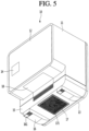
- Fig. 5 is a bottom perspective view of the entrance refrigerator 10.
- the entrance refrigerator 10 may include a cabinet 11, an outdoor side door 12, an indoor side door 13, and a housing 15.
- the cabinet 11 has a front opening provided in a portion of the cabinet 11 located at the front (exterior) side of the door or exterior wall, and a rear opening provided in a portion of the cabinet 11 located at the rear (interior) side of the door or interior wall.
- the cabinet 11 may have an approximately hexahedral shape with a front wall and a rear wall interconnected by a plurality of side walls.
- the front opening may be provided in the front wall of the cabinet 11, and the rear opening may be provided in the rear wall of the cabinet 11, although the embodiment is not limited thereto.
- the front opening and the rear opening may be provided on a same side of the cabinet 11 depending on the location where the entrance refrigerator 10 is being installed.
- the outdoor side door 12 may be rotatably coupled to the cabinet 11 so as to selectively open or close the front opening of the cabinet 11.
- the outdoor side door 12 may be opened by the delivery person in order to store goods in the entrance refrigerator 10.
- the outdoor side door 12 may be opened by the user so as to withdraw goods from the entrance refrigerator 10.
- the term "user” is defined as a person who has ordered goods that are stored in the entrance refrigerator 10 by the delivery person, or as a person having authority to release the goods from the entrance refrigerator 10.
- the indoor side door 13 may be rotatably coupled to the cabinet 11 so as to selectively open or close the rear opening of the cabinet 11.
- a display 14 may be provided on the outdoor side door 12.
- the display 14 may display information about an operating state of the entrance refrigerator 10, an internal temperature of the entrance refrigerator 10, and the presence or absence of goods in the entrance refrigerator 10.
- the delivery person who delivers goods may input a password or the like through the display 14 for opening the outdoor side door 12.
- a code scanner for recognizing an encryption code provided in a shipping order or a shipping box may be provided on one side of the outdoor side door 12.
- the indoor side door 13 is used by the user within the house to take out goods stored in the entrance refrigerator 10. That is, the user can open the indoor side door 13 to withdraw the goods from the entrance refrigerator 10 and into the house.
- a guide light 131 may be provided at one side of the indoor side door 13.
- the guide light 131 may be a device for informing a user whether or not goods are currently stored in the entrance refrigerator 10.
- the color of the guide light 131 may be set differently depending on whether goods are stored in the entrance refrigerator 10 or whether the entrance refrigerator 10 is empty. The user may recognize whether there are goods currently being stored even without opening the indoor side door 13.
- the housing 15 is provided at the lower end of the cabinet 11, either integrally as part of the cabinet 11 or as a separate element attached to the cabinet 11.
- a cold air supply device 30 (cold air supplier), to be described later, is accommodated in the housing 15.
- the front surface of the housing 15 comes into close proximity with the rear surface of the front door 1 or the wall when the entrance refrigerator 10 is mounted on the front door 1 or the wall, and contact between a portion of the front surface of the housing 15 and the rear surface of the front door 1 or the wall cancels the moment due to the eccentric load of the entrance refrigerator 10 within the opening of the front door 1 or the wall.
- the entrance refrigerator 10 has a structural characteristic in which a volume of a part exposed indoors is larger than a volume of a part exposed outdoors of the front door 1. Therefore, the center of gravity of the entrance refrigerator 10 is formed at a point eccentric rearwardly of the center of the entrance refrigerator 10. As a result, the moment is generated by the load of the entrance refrigerator 10 and the load of goods stored therein. With such an arrangement, it is possible that the entrance refrigerator 10 could be pulled out of the front door 1 by the moment.
- a pair of guide ducts 16 may be provided at left and right edges of the bottom surface of the housing 15.
- a discharge port 161 is formed at the front end of each guide duct 16 so that indoor room air, which flows into the cold air supply device 30 in the housing 15 and performs a heat dissipation function, may be discharged out of the housing 15.
- a guide plate 18 may be provided on an angled surface of the cabinet 11 formed by the bottom surface of the cabinet 11 and the front surface of the housing 15. The function of the guide plate 18 will be described below with reference to the accompanying drawings.
- An opening for suctioning indoor room air may be formed in the bottom surface of the housing 15, and a suction plate 17 may be mounted at the opening.
- a plurality of through-holes 171 may be formed in the suction plate 17, and indoor room air is introduced into the housing 15 through the plurality of through-holes 171. At least part of the indoor room air introduced into the housing 15 is discharged back out of the housing 15 through the discharge ports 161 of the guide ducts 16.
- Fig. 6 is a front perspective view of the entrance refrigerator 10 in a state in which the outdoor side door 12 is removed for clarity of illustration, according to an embodiment
- Fig. 7 is a rear perspective view of the entrance refrigerator 10 in a state in which the indoor side door 13 is removed for clarity of illustration, according to an embodiment.
- a storage compartment 111 in which goods may be stored is provided within the cabinet 11.
- the storage compartment 111 may be considered as a main body of the entrance refrigerator 10 according to the embodiment.
- a tray 19 on which goods are placed may be provided at a lower portion of the storage compartment 111.
- a guide rib 25 may be formed along the rear edge of the cabinet 11.
- the guide rib 25 may protrude a predetermined distance from the rear surface of the cabinet 11 and extend along an edge of the cabinet 11.
- the guide rib 25 is provided to guide some of the air discharged from the housing 15 upwardly to the area surrounding the indoor side door 13 so that condensation is prevented from forming on a gasket 22 surrounding the rear surface of the indoor side door 13.
- Fig. 8 is an exploded perspective view of the entrance refrigerator 10 according to an embodiment
- Fig. 9 is a cross-sectional view of the entrance refrigerator 10, taken along line 9-9 of Fig. 3
- Fig. 10 is a side cross-sectional view of the entrance refrigerator 10, taken along line 10-10 of Fig. 3 .
- the entrance refrigerator 10 may include the cabinet 11, the indoor side door 13, the outdoor side door 12, the housing 15, the guide duct 16, the suction plate 17, and the tray 19.
- the entrance refrigerator 10 may further include a base plate 20 disposed at the bottom portion of the cabinet 11.
- the tray 19 may be disposed above the base plate 20.
- the bottom surface of the tray 19 may be spaced apart upward from the base plate 20.
- the entrance refrigerator 10 may further include a cold air supply device 30 accommodated in the housing 15.
- the cold air supply device 30 may be a device to which a thermoelectric element (Peltier element) is applied, but the cold air supply device 30 is not limited thereto.
- a general cooling cycle may be applied to the cold air supply device 30.
- thermoelectric element When a current is supplied to the thermoelectric element, one surface thereof acts as a heat absorbing surface in which a temperature drops, and the other surface thereof acts as a heat generating surface in which a temperature increases.
- the heat absorbing surface and the heat generating surface are swapped.
- the cold air supply device 30 may include a thermoelectric element 31, a cold sink 32 attached to the heat absorbing surface of the thermoelectric element 31, a heat absorption fan 33 disposed above the cold sink 32, a heat sink 34 attached to the heat generating surface of the thermoelectric element 31, a heat dissipation fan 36 disposed below the heat sink 34, and an insulation material 35 for preventing heat transfer between the cold sink 32 and the heat sink 34.
- the insulation material 35 is provided to surround the side surface of the thermoelectric element 31.
- the cold sink 32 comes into contact with the upper surface of the insulation material 35, and the heat sink 34 comes into contact with the lower surface of the insulation material 35.
- the cold sink 32 and the heat sink 34 may include a thermal conductor directly attached to the heat absorbing surface and the heat generating surface, respectively, of the thermoelectric element 31, and a plurality of heat exchange fins extending from the surface of the thermal conductor.
- the heat absorption fan 33 is disposed to face the inside of the cabinet 11, and the heat dissipation fan 36 is disposed directly above the suction plate 17.
- the entrance refrigerator 10 may further include a mount plate 24 mounted on the bottom of the cabinet 11, and a flow guide 23 mounted on the upper surface of the mount plate 24.
- the mount plate 24 may be formed in a shape in which a rectangular plate is bent a plurality of times to include a bottom portion, a pair of upstanding side portions, and a pair of outwardly extending flange portions.
- the mount plate 24 may be formed in a shape in which a flow guide seating portion 241, on which the flow guide 23 is seated, is recessed or stepped to a predetermined depth.
- a through-hole 242 is formed at the bottom portion of the mount plate 24 defining the flow guide seating portion 241.
- a portion of the cold air supply device 30 may pass through the through-hole 242 and be mounted to the mount plate 24.
- the flow guide 23 may be understood as a device for forming the flow path of the air inside the storage compartment 111 which forcibly flows by the heat absorption fan 33.
- the base plate 20 may be disposed above the flow guide 23 to minimize a possibility that foreign substances could fall directly onto the flow guide 23.
- An outer gasket 21 is provided on an inner side of the outdoor side door 12 that faces the cabinet 11, and an inner gasket 22 is provided on an inner side of the indoor side door 13 that faces the cabinet 11.
- the outer gasket 21 and the inner gasket 22 prevent cold air within the storage compartment 111 from leaking to the outside of the entrance refrigerator 10.
- the outer gasket 21 may be provided on a portion of the cabinet 11 that faces an inner side of the outdoor side door 12, and the inner gasket 22 may be provided on a portion of the cabinet 11 that faces an inner side of the indoor side door 13.
- the portion of the cabinet 11 may be a contact shoulder 115 to be described later.
- the outer gasket 21 and the inner gasket 22 prevent cold air within the storage compartment 111 from leaking to the outside of the entrance refrigerator 10.
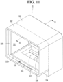
- Fig. 11 is a perspective view of the cabinet 11 constituting the entrance refrigerator 10, according to an embodiment
- Fig. 12 is a side cross-sectional view taken along line 12-12 of Fig. 11 .
- the cabinet 11 constituting the entrance refrigerator 10 according to the embodiment has a hexahedral shape in which the front side and the rear side are opened.
- the cabinet 11 may include a first portion 112 (exterior portion) inserted through the front door 1 or the wall, and a second portion 113 (interior portion) exposed to the inside.
- the lower end of the second portion 113 may extend downward further than the lower end of the first portion 112.
- the front surface of the second portion 113 extending downward from the rear end of the bottom of the first portion 112 may be defined as a door contact surface 114.
- the door contact surface 114 prevents the entrance refrigerator 10 from being separated from the front door 1 or the wall by the moment.
- a contact shoulder 115 may be formed at a point spaced apart rearward from the front end of the cabinet 11 by a predetermined distance.
- the contact shoulder 115 may protrude from the inner circumferential surface of the cabinet 11 by a predetermined height, and may have a rectangular band shape extending along the inner circumferential surface of the cabinet 11.
- a rectangular opening defined along the inner edge of the contact shoulder 115 may define an inlet portion for goods entering or exiting the storage compartment 111.
- a space between the front end of the cabinet 11 and a front surface of the contact shoulder 115 may be defined as an outdoor side door accommodation portion into which the outdoor side door 12 is received.
- the outer gasket 21 is in close contact with the front surface of the contact shoulder 115 to prevent leakage of cold air from the storage compartment 111.
- the longitudinal cross-section of the storage compartment 111 defined at the rear of the contact shoulder 115 may have the same size as the longitudinal cross-section of the inlet portion. That is, the bottom surface of the storage compartment 111 may be coplanar with the upper edge of the contact shoulder 115 extending from the inner circumferential surface of the bottom portion of the cabinet 11.
- the bottom surface of the storage compartment 111 may include the base plate 20.
- left and right side surfaces of the storage compartment 111 may be coplanar with the inner edges of the contact shoulder 115 extending from the left inner circumferential surface and the right inner circumferential surface of the cabinet 11, respectively.
- the ceiling surface of the storage compartment 111 may be coplanar with the lower edge of the contact shoulder 115 extending from the inner circumferential surface of the upper end of the cabinet 11.
- the inner circumferential surface of the storage compartment 111 is coplanar with the inner edges of the contact shoulder 115.
- the present disclosure is not limited to the above configuration.
- the bottom surface of the storage compartment 111 may be coplanar with the bottom surface of the outdoor side door accommodation portion.
- the contact shoulder 115 may be described as including a lower shoulder 115a, a left shoulder 115b, a right shoulder (see Figure 6 ), and an upper shoulder 115c, and the bottom surface (floor) of the storage compartment 111 may be designed to be lower than the upper edge of the lower shoulder 115a.
- left and right side surfaces of the storage compartment 111 may be designed to be wider than the inner edges of the left shoulder 115b and the right shoulder.
- the upper surface (ceiling) of the storage compartment 111 may be designed to be higher than the lower edge of the upper shoulder 115c.
- the width and height of the storage compartment 111 may be formed to be larger than the width and height of the inlet portion.
- a slot 116 may be formed at the bottom of the cabinet 11 corresponding to the bottom of the outdoor side door accommodation portion.
- the point where the slot 116 is formed is a point spaced a predetermined distance forward from the front surface of the contact shoulder 115.
- the slot 116 may be formed at a position closer to the contact shoulder 115 than to the front end of the cabinet 11. As the air that has a relatively high temperature and is discharged from the housing 15 rises, the air may be introduced into the outdoor side door accommodation portion of the cabinet 11 through the slot 116.
- the air flowing through the slot 116 flows along the edge of the outer gasket 21 to evaporate any condensation that may form on the outer gasket 21.
- an inwardly stepped portion 119 may be formed in the bottom surface of the cabinet 11 corresponding to the first portion 112 and in the front surface of the cabinet 11 corresponding to the second portion 113.
- the stepped portion 119 is enclosed by the guide plate 18, and an air flow passage 119a is formed between the guide plate 18 and the stepped portion 119.
- the lower end of the air flow passage 119a communicates with the inside of the housing 15, and the upper end of the air flow passage 119a is connected to the slot 116.
- the relatively high-temperature air discharged from the housing 15 moves along the air flow passage 119a and flows into the slot 116.
- a mount plate seating portion 117 may be formed at a predetermined depth on the inner bottom surface of the cabinet 11, particularly on the bottom surface of the cabinet 11 corresponding to the second portion 113.
- a cold air suction hole 118 may be formed on the bottom of the mount plate seating portion 117.
- the mount plate 24 is mounted on the mount plate seating portion 117 such that the through-hole 242 and the cold air suction hole 118 are aligned in the vertical direction.
- the flow guide 23 is disposed above the mount plate seating portion 117, particularly on the upper surface of the mount plate 24.
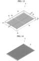
- Fig. 13 is a perspective view of the tray 19 accommodated in the storage compartment 111 of the entrance refrigerator 10, according to an embodiment.
- the tray 19 may include a rectangular bottom portion 191, an edge wall surrounding the edge of the bottom portion 191 and extending to a predetermined height, and legs 196 extending downward from four corners of the bottom portion 191.
- a plurality of through-holes 191a may be formed in the bottom portion 191.
- the edge wall may include a front portion 192, a left side portion 193, a right side portion 194, and a rear side portion 195.
- the bottom portion 191 is spaced apart from the bottom of the storage compartment 111 by the legs 196 to form a lower gap g1.
- the height of the lower gap g1 corresponds to the height of the legs 196, and the width of the lower gap g1 corresponds to the distance between two adjacent legs.
- the left-to-right width of the bottom portion 191 is formed to be smaller than the left-to-right width of the storage compartment 111, such that the edge wall of the tray 19 and the sidewall of the storage compartment 111 are separated by a predetermined distance to form a side gap g2.
- the front-to-rear width of the bottom portion 191 may also be formed to be smaller than the front-to-rear width of the storage compartment 111 to form a side gap.
- the side gap g2 may be about 5 mm, but the dimension of the gap g2 is not limited thereto.
- Fig. 14 is a perspective view of the base plate 20 disposed on the bottom of the storage compartment 111 of the entrance refrigerator 10, according to an embodiment.
- the base plate 20 may be formed to be the same size as the bottom portion 191 of the tray 19.
- the base plate 20 may be formed to be the same size as the bottom portion of the storage compartment 111.
- a plurality of through-holes 201 may be formed in the base plate 20, and the plurality of through-holes 201 may include circular holes or polygonal holes.
- the base plate 20 may be spaced apart from the bottom surface of the storage compartment 111 by a predetermined interval.
- the separation distance between the base plate 20 and the bottom surface of the storage compartment 111 is set to a dimension in consideration of the height of the lower shoulder 115a, so that the upper surface of the base plate 20 and the lower shoulder 115a may form the same plane.
- the lower shoulder 115a does not act as an obstacle that prevents the tray 19 from being inserted or withdrawn.
- the tray 19 can be pulled out by sliding the tray 19 on the base plate 20.
- the separation space is formed between the base plate 20 and the bottom surface of the storage compartment 111, the cold air guided by the flow guide 23 is evenly distributed throughout the lower portion of the storage compartment 111.
- the separation distance between the base plate 20 and the bottom surface of the storage compartment 111 may be about 15 mm, but the separation distance is not limited thereto.
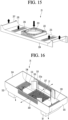
- Fig. 15 is a perspective view of the flow guide 23 disposed on the bottom of the entrance refrigerator 10, according to an embodiment.
- the flow guide 23 may include a bottom portion 231, curved portions 235 extending upward from the left and right edges of the bottom portion 231 in a rounded form, extension ends 234 extending downward from the front end and the rear end of the bottom portion 231 and the curved portions 235, and a fan housing 232 protruding upward from the center of the upper surface of the bottom portion 231.
- the extension ends 234 may include a front extension end extending downward from the front end of the bottom portion 231 and the front ends of the curved portions 235, and a rear extension end extending downward from the rear end of the bottom portion 231 and the rear ends of the curved portions 235.
- the ends of the curved portions 235 and the extension ends 234 define side discharge ports at the left and right edges of the flow guide 23, respectively.
- main discharge ports 236 may be formed at points spaced apart from the fan housing 232 to the left and the right of the fan housing 232 by a predetermined distance.
- the main discharge ports 236 may be formed by a plurality of slits that extend a predetermined length in the left-to-right direction of the flow guide 23 and are spaced apart in the front-to-rear direction of the flow guide 23.
- the main discharge ports 236 may also be provided in the form of one or more openings elongated in the front-to-rear direction of the flow guide 23.
- the fan housing 232 may protrude a predetermined height from the bottom portion 231 so as to accommodate the heat absorption fan 33.
- a suction port 233 may be formed in the upper surface of the fan housing 232.
- the left end and the right end of the flow guide 23 are in close contact with the left edge and the right edge of the mount plate seating portion 117.
- the side discharge ports 237 are formed on the upper surface of the flow guide 23, such that the cold air is discharged upward toward the ceiling of the storage compartment 111.
- Fig. 16 is a perspective view showing the internal structure of the housing 15 constituting the entrance refrigerator 10, according to an embodiment.
- the housing 15 is coupled to the lower end of the cabinet 11, specifically the lower end of the cabinet 11 defined as the second portion 113.
- One portion of the cold air supply device 30 is accommodated in the housing 15, and another portion of the cold air supply device 30 is accommodated in the lower space of the cabinet 11 corresponding to the second portion 113.
- the heat absorption fan 33, the cold sink 32, and the thermoelectric element 31 may be accommodated in the lower space of the second portion 113 of the cabinet 11, and the heat sink 34 and the heat dissipation fan 36 may be accommodated in the housing 15.
- this arrangement may be changed according to design conditions.
- the housing 15 may include a bottom portion 151, a front surface portion 152 extending upward from the front end of the bottom portion 151, a rear surface portion 153 extending upward from the rear end of the bottom portion 151, a left surface portion 154 extending upward from the left end of the bottom portion 151, and a right surface portion 155 extending upward from the right end of the bottom portion 151.
- a pair of guide ducts 16 are mounted on the bottom surface of the bottom portion 151.
- a suction hole 151a is formed at the center of the bottom portion 151, and a suction plate 17 is mounted over the suction hole 151a.
- a left discharge port 158 and a right discharge port 159 are formed on the left edge and the right edge of the bottom portion 151, respectively.
- the left discharge port 158 and the right discharge port 159 may be composed of an assembly of circular or polygonal holes. However, the present disclosure is not limited thereto, and each of the left discharge port 158 and the right discharge port 159 may have a rectangular hole shape having a predetermined width and length.
- the guide ducts 16 are mounted directly below the left discharge port 158 and the right discharge port 159, respectively.
- One or more flow guide plates 150 may be disposed on the upper surface of the bottom portion 151 corresponding to four corner portions of the suction hole 151a.
- a plurality of flow guide plates 150 may be disposed at the four corner portions of the suction hole 151a.
- a portion of outside air introduced into the housing 15 through the suction plate 17 that exchanges heat with the heat sink 34 may be guided to the left discharge port 158 and the right discharge port 159 by the flow guide plate 150.
- a front discharge port 156 and a rear discharge port 157 may be formed at the centers of the front surface portion 152 and the rear surface portion 153, respectively. A portion of the outside air introduced through the suction plate 17 may exchange heat with the heat sink 34 and may be discharged to the outside through the front discharge port 156 and the rear discharge port 157.
- the front discharge port 156 and the rear discharge port 157 may also be defined as an assembly of a plurality of holes, but the present disclosure is not limited thereto. However, since the discharge ports 156, 157, 158 and 159 are composed of a plurality of holes having a small diameter, it is possible to minimize the introduction of foreign substances into the housing 15.
- the guide plate 18 may be coupled to the cabinet 11 as an independent member, or may be a part of the housing 15 extending upward from the upper end of the front surface portion 152 and bent forward.
- the left surface portion 154 and the right surface portion 155 may extend upward from the left and right edges of the bottom portion 151 in a rounded form.
- Fig. 17 is a view showing the circulation of cold air inside the storage compartment 111 in a state in which goods are absent from the tray 19
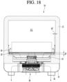
- Fig. 18 is a view showing the circulation of cold air inside the storage compartment 111 in a state in which goods are placed on the tray 19.
- thermoelectric element 31 acts as the heat absorbing surface and the lower surface acts as the heat generating surface, and the storage compartment 111 is kept in a refrigerating or freezing state.
- thermoelectric element 31 When a voltage is applied to the thermoelectric element 31, the temperature of the cold sink 32 attached to the heat absorbing surface of the thermoelectric element 31 is lowered, and the temperature of the heat sink 34 attached to the heat generating surface of the thermoelectric element 31 is raised.
- the air whose temperature is lowered flows in the left and right edge directions of the storage compartment 111 along the cold air flow path formed between the flow guide 23 and the mount plate 24.
- the air flowing to the left and right sides of the storage compartment 111 along the flow guide 23 flows into the storage compartment 111 through the main discharge port 236 and the side discharge port 237 formed in the flow guide 23.
- the cold air discharged to the storage compartment 111 through the main discharge ports 236 and the side discharge ports 237 passes through the base plate 20 and the bottom portion of the tray 19 and rises to the ceiling of the storage compartment 111.
- the air rising to the ceiling of the storage compartment 111 descends again to form a circulation flow path that returns back to the heat absorption fan 33.
- the indoor air introduced into the housing 15 exchanges heat with the heat sink 34 to increase the temperature of the air. That is, the heat is absorbed from the heat sink 34 to increase the temperature of the air.
- the indoor air whose temperature has risen is discharged in the front-to-rear direction and the horizontal direction of the entrance refrigerator 10 through the discharge ports 156, 157, 158 and 159.
- a portion of the air flowing toward the front discharge port 156 is guided to the slot 116 along the air flow passage 119a shown in Fig. 12 .
- the air guided to the left discharge port 158 and the right discharge port 159 flows forward of the housing 15 along the guide duct 16 and is then discharged to the outside of the housing 15 through the discharge ports 161. Since the discharge ports 161 are disposed close to the rear surface of the front door 1 or the wall in which the entrance refrigerator 10 is mounted, that is, the surface exposed to the inside, the air discharged to the discharge ports 161 may form a flow path that descends along the rear surface of the front door 1 or the wall.
- the air that encounters the flow resistance is dispersed horizontally in all directions and flows toward the edges of the tray 19 along the bottom surfaces of the goods.
- the cold air flowing toward the edges of the tray 19 passes through the lower gap g1 formed by the legs 196 of the tray 19.
- the cold air passing through the lower gap g1 rises through the side gap g2 formed between the four side edges of the tray 19 and the four side surfaces of the storage compartment 111.
- the bottom portion 191 of the tray 19 is spaced apart from the bottom of the storage compartment 111 by the length of the legs 196 and the lower gap g1 is formed, it is possible to prevent a blockage of the discharge flow path of the cold air guided to the storage compartment 111 by the flow guide 23.
- the side gap g2 is formed between the horizontal edge of the tray 19 and the inner wall of the storage compartment 111, the cold air flowing below the stored goods can flow to the upper side of the storage compartment 111 without hovering only on the lower side of the tray 19.
- Fig. 19 is a front cross-sectional view of the entrance refrigerator 10, taken along line 19-19 of Fig. 3 , showing the flow passage structure for preventing condensation formation around the outdoor side door 12, and Fig. 20 is a cutaway perspective view of the entrance refrigerator 10, taken along line 20-20 of Fig. 19 .
- the slot 116 is formed at the bottom of the front end of the cabinet 11, as described with reference to Fig. 11 .
- the stepped portion 119 is inwardly formed on the front surface of the second portion 113 of the cabinet 11 and the bottom surface of the first portion 112.
- the stepped portion 119 is enclosed by the guide plate 18.
- the guide plate 18 may be formed as an extension of the front surface portion of the housing 15, or the guide plate 18 may be provided as a separate member coupled to the cabinet 11.
- the air flow passage 119a is formed between the stepped portion 119 and the guide plate 18. One end of the air flow passage 119a communicates with the inside of the housing 15, and the other end of the air flow passage 119a communicates with the slot 116.
- a portion of the indoor air whose temperature has risen flows to the slot 116 along the air flow passage 119a.
- Another portion of the air inside the housing 15 whose temperature has risen is discharged to the outside of the entrance refrigerator 10 through the front discharge port 156.
- the air passing through the slot 116 moves along the space between the rear edge of the outdoor side door 12 and the front end of the cabinet 11.
- the outer gasket 21 surrounds the rear edge of the outdoor side door 12
- the high temperature air passing through the slot 116 hits the outer circumferential surface of the outer gasket 21 and flows left and right along the lower side of the outer gasket 21 at the lower end of the outdoor side door 12.
- the air reaching the left and right edges of the outer gasket 21 then rises along the left and right sides of the outer gasket 21 along the left and right sides, respectively, of the outdoor side door 12.
- outer gasket 21 is attached to a point spaced apart from the four side edges of the outdoor side door 12 by a predetermined distance in the central direction.
- a rectangular band-shaped air pocket 110 is formed by the inner circumferential surface of the cabinet 11, the front surface of the contact shoulder 115, the rear edge of the outdoor side door 12, and the outer surface of the outer gasket 21.
- the center of the lower end of the rectangular band-shaped air pocket 110 communicates with the slot 116, and the slot 116 communicates with the inner space of the housing 15 by way of the air flow passage 119a.
- the air pocket 110 is filled with air having a temperature higher than the outdoor air temperature, condensation formation typically will not occur around the outer gasket 21. In addition, even if condensation formation occurs, the formed condensation quickly evaporates due to the flow of air around the outer gasket 21.
- An air hole 110a may be formed in the cabinet 11 to permit the air within the air pocket 110 to be discharged out of the air pocket at the center of the upper end of the air pocket 110.
- the air inside the air pocket 110 may not properly remove the condensation formed on the outer gasket 21.
- the air hole 110a may be formed in the upper region of the cabinet 11 defining the outdoor side door accommodation portion, that is, the front end region of the cabinet 11 corresponding to the point where two air flows, flowing inwardly along the upper portion of the air pocket 110 from the right side and the left side, join together.
- gaps may be provided between the outer periphery of the outdoor side door 12 and the inner periphery of the outdoor side door accommodation portion of the cabinet 11, as shown in the upper enlargement in Fig. 20 , to permit air in the air pocket 110 to escape in order to prevent stagnation of the air in the air pocket 110.
- the gaps may be provided together with the air hole 110a, or instead of the air hole 110a.
Landscapes
- Engineering & Computer Science (AREA)
- Physics & Mathematics (AREA)
- Mechanical Engineering (AREA)
- Thermal Sciences (AREA)
- General Engineering & Computer Science (AREA)
- Chemical & Material Sciences (AREA)
- Combustion & Propulsion (AREA)
- Cold Air Circulating Systems And Constructional Details In Refrigerators (AREA)
- Devices That Are Associated With Refrigeration Equipment (AREA)
Claims (15)
- Kühlschrank (10), der aufweist:ein Außengehäuse (11), das geeignet ist, so installiert zu werden, dass es durch eine Tür oder eine Wand geht oder in diese eingesetzt ist, und das ein Aufbewahrungsfach (111) zur Aufbewahrung von Waren bildet;ein Gehäuse (15), das mit einem Teil des Außengehäuses (11) gekoppelt oder integral damit ausgebildet ist;eine Außenseitentür (12), die konfiguriert ist, eine Vorderseite des Aufbewahrungsfachs (111) zu öffnen oder zu schließen und zur Außenseite eines Raums freiliegt, wobei die Tür oder die Wand eine Begrenzung des Raums darstellt;eine Innenseitentür (13), die konfiguriert ist, dass sie eine Rückseite des Aufbewahrungsfachs (111) zu öffnen oder zu schließen und zu einer Innenseite des Raums freiliegt; undeine Kaltluftzufuhrvorrichtung, von der mindestens ein Teil im Gehäuse (15) angeordnet ist und die konfiguriert ist, die Luft im Aufbewahrungsfach (111) zu kühlen,dadurch gekennzeichnet, dass der Kühlschrank ferner eine äußere Dichtung (21) aufweist, die eine Hinterkante der Außenseitentür (12) umgibt;wobei das Außengehäuse (11) eine Kontaktschulter (115) aufweist, die von einer Innenumfangsfläche des Außengehäuses (11) nach innen vorsteht und von einem vorderen Ende des Außengehäuses (11) um einen vorbestimmten Abstand nach hinten beabstandet angeordnet ist,wobei, wenn die Außenseitentür (12) geschlossen ist, die äußere Dichtung (21) konfiguriert ist, in Kontakt mit einer vorderen Fläche der Kontaktschulter (115) zu kommen,wobei ein Führungsloch (116) an einem Abschnitt des Außengehäuses (11) zwischen der vorderen Fläche der Kontaktschulter (115) und dem vorderen Ende des Außengehäuses (11) ausgebildet ist, undwobei ein Führungsströmungskanal (119a), der einen Innenraum des Gehäuses (15) und das Führungsloch (116) verbindet, im Außengehäuse (11) ausgebildet ist, so dass ein Teil der Innenluft, deren Temperatur durch Wärmeaustausch mit einer Wärmesenke (34) der Kaltluftzufuhrvorrichtung erhöht wurde, entlang der äußeren Dichtung (21) aufsteigt, die sich an der Rückseite der Außenseitentür (12) befindet.
- Kühlschrank nach Anspruch 1, wobei das Gehäuse (15) mit einem unteren Teil des Außengehäuses (11) gekoppelt oder integral damit ausgebildet ist.
- Kühlschrank nach Anspruch 1 oder 2, wobei das Führungsloch (116) an einem unteren Teil des Außengehäuses ausgebildet ist und der Führungsströmungskanal (119a) an einem unteren Teil des Außengehäuses (11) angeordnet ist.
- Kühlschrank nach einem der Ansprüche 1 bis 3, wobei ein Raum zwischen dem vorderen Ende des Außengehäuses (11) und der Kontaktschulter (115) als ein Außenseitentür-Aufnahmeabschnitt definiert ist, und
wobei eine bandförmige Lufttasche, die durch eine Innenumfangsfläche des Außengehäuses (11), eine vordere Fläche der Kontaktschulter (115), eine hintere Fläche der Außenseitentür (12) und eine äußere Fläche der äußeren Dichtung (21) definiert ist, im Außenseitentür-Aufnahmeabschnitt ausgebildet ist. - Kühlschrank nach Anspruch 4, wobei die Lufttasche so konfiguriert ist, dass sie mit dem Führungsloch (116) in Verbindung steht.
- Kühlschrank nach Anspruch 4 oder 5, wobei das Außengehäuse (11) aufweist:einen ersten Abschnitt (112), der in die Tür oder die Wand eingesetzt ist; undeinen zweiten Abschnitt (113), der an einer Rückseite des ersten Abschnitts (112) ausgebildet ist,wobei ein unteres Ende des zweiten Abschnitts (113) sich weiter nach unten erstreckt als ein unteres Ende des ersten Abschnitts (112), undwobei eine vordere Fläche des zweiten Abschnitts (113) so angeordnet ist, dass sie mit der Tür oder der Wand in Kontakt kommt.
- Kühlschrank nach Anspruch 6, insofern als von Anspruch 3 abhängig, wobei das Außengehäuse (11) einen abgestuften Abschnitt (119) aufweist, der von der vorderen Fläche des zweiten Abschnitts (113) und einer unteren Fläche des ersten Abschnitts (112) um eine vorbestimmte Breite und Tiefe ausgespart ist.
- Kühlschrank nach Anspruch 7, der ferner eine Führungsplatte (18) aufweist, die eine geöffnete Vorderfläche des abgestuften Abschnitts (119) abdeckt,
wobei der Führungsströmungskanal (119a) zwischen der Führungsplatte (18) und dem gestuften Abschnitt (119) ausgebildet ist. - Kühlschrank nach Anspruch 8, wobei die Führungsplatte (18) ein Element ist, das sich von einem vorderen oberen Ende des Gehäuses (15) erstreckt.
- Kühlschrank nach einem der Ansprüche 4 bis 9, wobei ein Luftloch (110) an einem vorderen oberen Ende des Außengehäuses (11) ausgebildet ist, das einem Punkt entspricht, an dem Luft, die von einer linken Seite und einer rechten Seite der Lufttasche strömt, aufeinander trifft.
- Kühlschrank nach einem der Ansprüche 1 bis 10, der ferner eine innere Dichtung (22) aufweist, die an einer hinteren Fläche der Innenseitentür (13) angeordnet ist, um zu verhindern, dass kalte Luft des Aufbewahrungsfachs (111) zur Außenseite des Kühlschranks (10) entweicht.
- Kühlschrank nach einem der Ansprüche 1 bis 11, wobei die Kaltluftzufuhrvorrichtung aufweist:ein thermoelektrisches Element (31) mit einer wärmeabsorbierenden Fläche und einer wärmeerzeugenden Fläche;eine Kältesenke (32), die in Kontakt mit der wärmeabsorbierenden Fläche steht; undeine Wärmesenke (34), die in Kontakt mit der wärmeerzeugenden Fläche steht.
- Kühlschrank nach Anspruch 12, wobei die Kaltluftzufuhrvorrichtung ferner aufweist:einen Wärmeabsorptionsventilator (33), der an oder über der Kältesenke (32) angeordnet ist;einen Wärmeableitungsventilator (36), der an oder unter der Wärmesenke (34) angeordnet ist; undein Isoliermaterial (35), das zwischen der Kältesenke (32) und der Wärmesenke (34) angeordnet ist.
- Kühlschrank nach Anspruch 13, insofern als von Anspruch 6 abhängig, wobei ein Kaltluftansaugloch (118) an einem Boden des Aufbewahrungsfachs (111) entsprechend dem zweiten Abschnitt (113) ausgebildet ist,wobei mindestens eines des Wärmeabsorptionsventilators (33), der Kältesenke (32), des thermoelektrischen Elements (31) und des Isolationsmaterials (35) im Kaltluftsaugloch (118) untergebracht ist, undwobei vorzugsweise mindestens ein Abschnitt der Wärmesenke (34) oder des Wärmeableitungsventilators (36) im Gehäuse (15) untergebracht ist.
- Kühlschrank nach Anspruch 14, wobei an einem Boden des Gehäuses (15) eine Ansaugplatte (17) angebracht ist, in der mehrere Durchgangslöcher ausgebildet sind, wobei Luft in das Gehäuse (15) durch die Ansaugplatte (17) eingeleitet wird, indem der Wärmeableitungsventilator (36) angetrieben wird, um Wärme zu absorbieren, während sie an der Wärmesenke (34) vorbeigeht.
Applications Claiming Priority (2)
| Application Number | Priority Date | Filing Date | Title |
|---|---|---|---|
| KR1020190021867A KR102766351B1 (ko) | 2019-02-25 | 2019-02-25 | 현관용 냉장고 |
| KR1020190086978A KR102858746B1 (ko) | 2019-07-18 | 2019-07-18 | 현관용 냉장고 |
Publications (2)
| Publication Number | Publication Date |
|---|---|
| EP3699529A1 EP3699529A1 (de) | 2020-08-26 |
| EP3699529B1 true EP3699529B1 (de) | 2024-01-17 |
Family
ID=69726465
Family Applications (1)
| Application Number | Title | Priority Date | Filing Date |
|---|---|---|---|
| EP20158933.0A Active EP3699529B1 (de) | 2019-02-25 | 2020-02-24 | Eintrittskühlschrank |
Country Status (3)
| Country | Link |
|---|---|
| US (1) | US11808512B2 (de) |
| EP (1) | EP3699529B1 (de) |
| CN (1) | CN111609648A (de) |
Families Citing this family (3)
| Publication number | Priority date | Publication date | Assignee | Title |
|---|---|---|---|---|
| CN112856853A (zh) * | 2021-02-02 | 2021-05-28 | 桂林理工大学 | 一种自主感知温度并智能调节冷热的装置 |
| CN114963640B (zh) * | 2021-02-18 | 2024-05-24 | 内蒙古伊利实业集团股份有限公司 | 门组件及冷柜 |
| US20250139568A1 (en) * | 2021-12-29 | 2025-05-01 | Home Valet, Inc. | Demographic and identity verification for delivery restrictions |
Family Cites Families (55)
| Publication number | Priority date | Publication date | Assignee | Title |
|---|---|---|---|---|
| US3052100A (en) * | 1960-08-22 | 1962-09-04 | Gen Electric | Refrigeration system |
| US3078682A (en) | 1961-05-29 | 1963-02-26 | Gen Motors Corp | Thermoelectric refrigerating apparatus |
| US3177678A (en) | 1961-09-26 | 1965-04-13 | Westinghouse Electric Corp | Refrigerating apparatus |
| FR1347414A (fr) | 1963-01-29 | 1963-12-27 | Borg Warner | Réfrigérateur thermo-électrique |
| US4738113A (en) | 1985-10-18 | 1988-04-19 | The Cola-Cola Company | Combination cooler and freezer for refrigerating containers and food in outer space |
| US4726193C2 (en) | 1987-02-13 | 2001-03-27 | Marlow Ind Inc | Temperature controlled picnic box |
| JPH05149675A (ja) | 1991-11-27 | 1993-06-15 | Matsushita Refrig Co Ltd | 冷蔵庫 |
| US5315830B1 (en) | 1993-04-14 | 1998-04-07 | Marlow Ind Inc | Modular thermoelectric assembly |
| CN2165389Y (zh) | 1993-10-06 | 1994-05-18 | 井侠 | 悬挂式小冰箱 |
| US5774053A (en) * | 1996-05-02 | 1998-06-30 | Porter; David | Storage device for the delivery and pickup of goods |
| TW499559B (en) | 1997-01-31 | 2002-08-21 | Gac Corp | Cold storage apparatus |
| JPH10267501A (ja) * | 1997-03-28 | 1998-10-09 | Sanyo Electric Co Ltd | 業務用冷蔵庫 |
| JPH1194423A (ja) | 1997-09-19 | 1999-04-09 | Kazumi Yamamoto | 冷水発生ポット |
| DE19909794A1 (de) | 1998-11-25 | 2000-09-07 | Bayerische Motoren Werke Ag | Vorrichtung für einen abschließbaren Raum eines Fahrzeugs |
| US20050122682A1 (en) | 2000-12-08 | 2005-06-09 | Robert Streit | Electronics arrangement |
| US6715299B2 (en) | 2001-10-19 | 2004-04-06 | Samsung Electronics Co., Ltd. | Refrigerator for cosmetics and method of controlling the same |
| US7101341B2 (en) | 2003-04-15 | 2006-09-05 | Ross Tsukashima | Respiratory monitoring, diagnostic and therapeutic system |
| US7451603B2 (en) * | 2004-03-22 | 2008-11-18 | General Mills, Inc. | Portable cooled merchandizing unit |
| CA2461635A1 (en) | 2004-03-22 | 2005-09-22 | Marc Bedard | Refrigerated display case |
| US7934384B2 (en) | 2004-10-22 | 2011-05-03 | General Mills, Inc. | Portable cooled merchandizing unit with customer enticement features |
| WO2006087690A2 (en) * | 2005-02-21 | 2006-08-24 | Arcelik Anonim Sirketi | A cooling device |
| US7308796B1 (en) | 2005-06-03 | 2007-12-18 | Eager Jacob P | Fruit refrigerator |
| CN100549587C (zh) * | 2006-12-26 | 2009-10-14 | 财团法人工业技术研究院 | 除雾装置 |
| DE202008012058U1 (de) * | 2008-07-17 | 2009-11-26 | Liebherr-Hausgeräte Lienz Gmbh | Kühl- und/oder Gefriergerät |
| JP5372432B2 (ja) * | 2008-08-21 | 2013-12-18 | 三洋電機株式会社 | 低温ショーケース |
| CN201277783Y (zh) | 2008-08-25 | 2009-07-22 | 河南新飞电器有限公司 | 冰箱排水管 |
| KR20110033394A (ko) | 2009-09-25 | 2011-03-31 | 조영택 | 현관문 및 대문에 부착되는 냉장고 |
| CN102914119B (zh) | 2011-07-31 | 2016-08-10 | 博西华家用电器有限公司 | 制冷器具 |
| CN102589236B (zh) | 2012-02-22 | 2014-08-13 | 合肥美的电冰箱有限公司 | 冰箱及其排水管组件 |
| CN102927748B (zh) | 2012-11-26 | 2015-05-13 | 合肥美的电冰箱有限公司 | 用于冷柜的排水管组件及具有其的冷柜 |
| CN203534032U (zh) | 2013-08-02 | 2014-04-09 | 青岛海尔特种电冰箱有限公司 | 用于冰箱的排水管和冰箱 |
| EP2980511A1 (de) | 2014-08-01 | 2016-02-03 | Werner W. Lorke | Kühlgeräte, Kühlmodule und Kühlrippenmodule sowie deren Verwendung |
| CN105389944A (zh) | 2015-12-03 | 2016-03-09 | 长春工业大学 | 车内滞留儿童预警及自动救助系统 |
| KR20170087705A (ko) | 2016-01-21 | 2017-07-31 | 삼성전자주식회사 | 보관장치 및 그 제어방법 |
| US9750355B1 (en) | 2016-03-02 | 2017-09-05 | Pepsico, Inc. | Refrigerated merchandise display system |
| JP6751909B2 (ja) | 2016-04-25 | 2020-09-09 | パナソニックIpマネジメント株式会社 | 冷蔵宅配ボックス、およびこれに用いる宅配ボックス |
| KR102632585B1 (ko) | 2016-09-29 | 2024-02-02 | 엘지전자 주식회사 | 냉장고 |
| KR102632586B1 (ko) | 2016-09-29 | 2024-02-02 | 엘지전자 주식회사 | 냉장고 |
| CN206362072U (zh) | 2016-11-30 | 2017-07-28 | 合肥晶弘三菱电机家电技术开发有限公司 | 一种冰箱用接水盘及冰箱 |
| CN206257869U (zh) | 2016-12-14 | 2017-06-16 | 海信(山东)冰箱有限公司 | 一种冷藏装置及其排水组件 |
| EP3348933B1 (de) | 2017-01-04 | 2022-03-30 | LG Electronics Inc. | Kühlschrank |
| KR102467404B1 (ko) * | 2017-03-21 | 2022-11-16 | 엘지전자 주식회사 | 냉장고 |
| KR102311397B1 (ko) | 2017-04-03 | 2021-10-13 | 엘지전자 주식회사 | 냉장고 |
| CN107084583B (zh) | 2017-04-25 | 2024-03-26 | 青岛海尔特种电冰柜有限公司 | 制冷电器 |
| CN108800656B (zh) | 2017-04-28 | 2020-09-08 | 青岛海尔智能技术研发有限公司 | 半导体制冷模组及制冷设备 |
| CN207006712U (zh) | 2017-06-26 | 2018-02-13 | 合肥华凌股份有限公司 | 用于制冷器具的安全防护组件、安全防护系统及制冷器具 |
| US10824175B2 (en) | 2017-07-28 | 2020-11-03 | Stmicroelectronics, Inc. | Air flow measurement using pressure sensors |
| KR102342315B1 (ko) | 2017-08-24 | 2021-12-24 | 에스케이하이닉스 주식회사 | 반도체 장치 및 반도체 시스템 |
| CN107440482A (zh) | 2017-09-26 | 2017-12-08 | 深圳市创新先进科技有限公司 | 一种可保鲜冷藏的电煲 |
| CN108344233A (zh) | 2017-12-20 | 2018-07-31 | 青岛海尔股份有限公司 | 用于冰箱的排水管组件及冰箱 |
| CN108458540B (zh) | 2017-12-20 | 2021-02-26 | 海尔智家股份有限公司 | 用于冰箱的排水管组件及冰箱 |
| KR102028366B1 (ko) | 2018-01-15 | 2019-10-04 | 한국세라믹기술원 | 사파이어 종자결정상에서 질화알루미늄을 성장시키는 방법 |
| US10820733B2 (en) * | 2018-01-26 | 2020-11-03 | Lennar Ventures | Delivery compartment |
| CN207922675U (zh) | 2018-02-26 | 2018-09-28 | 合肥美的电冰箱有限公司 | 冰箱排水管结构及冰箱 |
| CN207922676U (zh) | 2018-03-07 | 2018-09-28 | 海信(山东)冰箱有限公司 | 接水槽及冰箱 |
-
2020
- 2020-02-20 CN CN202010106017.0A patent/CN111609648A/zh active Pending
- 2020-02-24 EP EP20158933.0A patent/EP3699529B1/de active Active
- 2020-02-24 US US16/798,600 patent/US11808512B2/en active Active
Also Published As
| Publication number | Publication date |
|---|---|
| CN111609648A (zh) | 2020-09-01 |
| US11808512B2 (en) | 2023-11-07 |
| EP3699529A1 (de) | 2020-08-26 |
| US20200271368A1 (en) | 2020-08-27 |
Similar Documents
| Publication | Publication Date | Title |
|---|---|---|
| EP3699532B1 (de) | Eintrittskühlschrank | |
| US11808512B2 (en) | Entrance refrigerator | |
| EP3699525B1 (de) | Eintrittskühlschrank | |
| EP3699524B1 (de) | Eintrittskühlschrank | |
| US11448456B2 (en) | Entrance refrigerator | |
| US11293684B2 (en) | Entrance refrigerator | |
| US11255584B2 (en) | Entrance refrigerator | |
| EP3699528B1 (de) | Eintrittskühlschrank | |
| US11441833B2 (en) | Entrance refrigerator | |
| KR102858733B1 (ko) | 현관용 냉장고 | |
| KR102858746B1 (ko) | 현관용 냉장고 | |
| US11274858B2 (en) | Entrance refrigerator | |
| KR20210087151A (ko) | 현관용 냉장고 | |
| KR20210009848A (ko) | 현관용 냉장고 | |
| KR20210009850A (ko) | 현관용 냉장고 |
Legal Events
| Date | Code | Title | Description |
|---|---|---|---|
| PUAI | Public reference made under article 153(3) epc to a published international application that has entered the european phase |
Free format text: ORIGINAL CODE: 0009012 |
|
| STAA | Information on the status of an ep patent application or granted ep patent |
Free format text: STATUS: REQUEST FOR EXAMINATION WAS MADE |
|
| 17P | Request for examination filed |
Effective date: 20200324 |
|
| AK | Designated contracting states |
Kind code of ref document: A1 Designated state(s): AL AT BE BG CH CY CZ DE DK EE ES FI FR GB GR HR HU IE IS IT LI LT LU LV MC MK MT NL NO PL PT RO RS SE SI SK SM TR |
|
| AX | Request for extension of the european patent |
Extension state: BA ME |
|
| RBV | Designated contracting states (corrected) |
Designated state(s): AL AT BE BG CH CY CZ DE DK EE ES FI FR GB GR HR HU IE IS IT LI LT LU LV MC MK MT NL NO PL PT RO RS SE SI SK SM TR |
|
| GRAP | Despatch of communication of intention to grant a patent |
Free format text: ORIGINAL CODE: EPIDOSNIGR1 |
|
| STAA | Information on the status of an ep patent application or granted ep patent |
Free format text: STATUS: GRANT OF PATENT IS INTENDED |
|
| INTG | Intention to grant announced |
Effective date: 20230802 |
|
| GRAS | Grant fee paid |
Free format text: ORIGINAL CODE: EPIDOSNIGR3 |
|
| GRAA | (expected) grant |
Free format text: ORIGINAL CODE: 0009210 |
|
| STAA | Information on the status of an ep patent application or granted ep patent |
Free format text: STATUS: THE PATENT HAS BEEN GRANTED |
|
| AK | Designated contracting states |
Kind code of ref document: B1 Designated state(s): AL AT BE BG CH CY CZ DE DK EE ES FI FR GB GR HR HU IE IS IT LI LT LU LV MC MK MT NL NO PL PT RO RS SE SI SK SM TR |
|
| REG | Reference to a national code |
Ref country code: GB Ref legal event code: FG4D |
|
| REG | Reference to a national code |
Ref country code: CH Ref legal event code: EP |
|
| REG | Reference to a national code |
Ref country code: DE Ref legal event code: R096 Ref document number: 602020024355 Country of ref document: DE |
|
| REG | Reference to a national code |
Ref country code: IE Ref legal event code: FG4D |
|
| REG | Reference to a national code |
Ref country code: LT Ref legal event code: MG9D |
|
| REG | Reference to a national code |
Ref country code: NL Ref legal event code: MP Effective date: 20240117 |
|
| REG | Reference to a national code |
Ref country code: AT Ref legal event code: MK05 Ref document number: 1650781 Country of ref document: AT Kind code of ref document: T Effective date: 20240117 |
|
| PG25 | Lapsed in a contracting state [announced via postgrant information from national office to epo] |
Ref country code: NL Free format text: LAPSE BECAUSE OF FAILURE TO SUBMIT A TRANSLATION OF THE DESCRIPTION OR TO PAY THE FEE WITHIN THE PRESCRIBED TIME-LIMIT Effective date: 20240117 |
|
| PG25 | Lapsed in a contracting state [announced via postgrant information from national office to epo] |
Ref country code: NL Free format text: LAPSE BECAUSE OF FAILURE TO SUBMIT A TRANSLATION OF THE DESCRIPTION OR TO PAY THE FEE WITHIN THE PRESCRIBED TIME-LIMIT Effective date: 20240117 |
|
| PG25 | Lapsed in a contracting state [announced via postgrant information from national office to epo] |
Ref country code: IS Free format text: LAPSE BECAUSE OF FAILURE TO SUBMIT A TRANSLATION OF THE DESCRIPTION OR TO PAY THE FEE WITHIN THE PRESCRIBED TIME-LIMIT Effective date: 20240517 |
|
| PG25 | Lapsed in a contracting state [announced via postgrant information from national office to epo] |
Ref country code: LT Free format text: LAPSE BECAUSE OF FAILURE TO SUBMIT A TRANSLATION OF THE DESCRIPTION OR TO PAY THE FEE WITHIN THE PRESCRIBED TIME-LIMIT Effective date: 20240117 |
|
| PG25 | Lapsed in a contracting state [announced via postgrant information from national office to epo] |
Ref country code: GR Free format text: LAPSE BECAUSE OF FAILURE TO SUBMIT A TRANSLATION OF THE DESCRIPTION OR TO PAY THE FEE WITHIN THE PRESCRIBED TIME-LIMIT Effective date: 20240418 |
|
| PG25 | Lapsed in a contracting state [announced via postgrant information from national office to epo] |
Ref country code: RS Free format text: LAPSE BECAUSE OF FAILURE TO SUBMIT A TRANSLATION OF THE DESCRIPTION OR TO PAY THE FEE WITHIN THE PRESCRIBED TIME-LIMIT Effective date: 20240417 Ref country code: HR Free format text: LAPSE BECAUSE OF FAILURE TO SUBMIT A TRANSLATION OF THE DESCRIPTION OR TO PAY THE FEE WITHIN THE PRESCRIBED TIME-LIMIT Effective date: 20240117 |
|
| PG25 | Lapsed in a contracting state [announced via postgrant information from national office to epo] |
Ref country code: ES Free format text: LAPSE BECAUSE OF FAILURE TO SUBMIT A TRANSLATION OF THE DESCRIPTION OR TO PAY THE FEE WITHIN THE PRESCRIBED TIME-LIMIT Effective date: 20240117 |
|
| PG25 | Lapsed in a contracting state [announced via postgrant information from national office to epo] |
Ref country code: AT Free format text: LAPSE BECAUSE OF FAILURE TO SUBMIT A TRANSLATION OF THE DESCRIPTION OR TO PAY THE FEE WITHIN THE PRESCRIBED TIME-LIMIT Effective date: 20240117 |
|
| PG25 | Lapsed in a contracting state [announced via postgrant information from national office to epo] |
Ref country code: RS Free format text: LAPSE BECAUSE OF FAILURE TO SUBMIT A TRANSLATION OF THE DESCRIPTION OR TO PAY THE FEE WITHIN THE PRESCRIBED TIME-LIMIT Effective date: 20240417 Ref country code: NO Free format text: LAPSE BECAUSE OF FAILURE TO SUBMIT A TRANSLATION OF THE DESCRIPTION OR TO PAY THE FEE WITHIN THE PRESCRIBED TIME-LIMIT Effective date: 20240417 Ref country code: LT Free format text: LAPSE BECAUSE OF FAILURE TO SUBMIT A TRANSLATION OF THE DESCRIPTION OR TO PAY THE FEE WITHIN THE PRESCRIBED TIME-LIMIT Effective date: 20240117 Ref country code: IS Free format text: LAPSE BECAUSE OF FAILURE TO SUBMIT A TRANSLATION OF THE DESCRIPTION OR TO PAY THE FEE WITHIN THE PRESCRIBED TIME-LIMIT Effective date: 20240517 Ref country code: HR Free format text: LAPSE BECAUSE OF FAILURE TO SUBMIT A TRANSLATION OF THE DESCRIPTION OR TO PAY THE FEE WITHIN THE PRESCRIBED TIME-LIMIT Effective date: 20240117 Ref country code: GR Free format text: LAPSE BECAUSE OF FAILURE TO SUBMIT A TRANSLATION OF THE DESCRIPTION OR TO PAY THE FEE WITHIN THE PRESCRIBED TIME-LIMIT Effective date: 20240418 Ref country code: FI Free format text: LAPSE BECAUSE OF FAILURE TO SUBMIT A TRANSLATION OF THE DESCRIPTION OR TO PAY THE FEE WITHIN THE PRESCRIBED TIME-LIMIT Effective date: 20240117 Ref country code: ES Free format text: LAPSE BECAUSE OF FAILURE TO SUBMIT A TRANSLATION OF THE DESCRIPTION OR TO PAY THE FEE WITHIN THE PRESCRIBED TIME-LIMIT Effective date: 20240117 Ref country code: BG Free format text: LAPSE BECAUSE OF FAILURE TO SUBMIT A TRANSLATION OF THE DESCRIPTION OR TO PAY THE FEE WITHIN THE PRESCRIBED TIME-LIMIT Effective date: 20240117 Ref country code: AT Free format text: LAPSE BECAUSE OF FAILURE TO SUBMIT A TRANSLATION OF THE DESCRIPTION OR TO PAY THE FEE WITHIN THE PRESCRIBED TIME-LIMIT Effective date: 20240117 |
|
| PG25 | Lapsed in a contracting state [announced via postgrant information from national office to epo] |
Ref country code: PL Free format text: LAPSE BECAUSE OF FAILURE TO SUBMIT A TRANSLATION OF THE DESCRIPTION OR TO PAY THE FEE WITHIN THE PRESCRIBED TIME-LIMIT Effective date: 20240117 Ref country code: PT Free format text: LAPSE BECAUSE OF FAILURE TO SUBMIT A TRANSLATION OF THE DESCRIPTION OR TO PAY THE FEE WITHIN THE PRESCRIBED TIME-LIMIT Effective date: 20240517 |
|
| PG25 | Lapsed in a contracting state [announced via postgrant information from national office to epo] |
Ref country code: SE Free format text: LAPSE BECAUSE OF FAILURE TO SUBMIT A TRANSLATION OF THE DESCRIPTION OR TO PAY THE FEE WITHIN THE PRESCRIBED TIME-LIMIT Effective date: 20240117 Ref country code: PT Free format text: LAPSE BECAUSE OF FAILURE TO SUBMIT A TRANSLATION OF THE DESCRIPTION OR TO PAY THE FEE WITHIN THE PRESCRIBED TIME-LIMIT Effective date: 20240517 Ref country code: PL Free format text: LAPSE BECAUSE OF FAILURE TO SUBMIT A TRANSLATION OF THE DESCRIPTION OR TO PAY THE FEE WITHIN THE PRESCRIBED TIME-LIMIT Effective date: 20240117 Ref country code: LV Free format text: LAPSE BECAUSE OF FAILURE TO SUBMIT A TRANSLATION OF THE DESCRIPTION OR TO PAY THE FEE WITHIN THE PRESCRIBED TIME-LIMIT Effective date: 20240117 |
|
| REG | Reference to a national code |
Ref country code: CH Ref legal event code: PL |
|
| PG25 | Lapsed in a contracting state [announced via postgrant information from national office to epo] |
Ref country code: DK Free format text: LAPSE BECAUSE OF FAILURE TO SUBMIT A TRANSLATION OF THE DESCRIPTION OR TO PAY THE FEE WITHIN THE PRESCRIBED TIME-LIMIT Effective date: 20240117 |
|
| PG25 | Lapsed in a contracting state [announced via postgrant information from national office to epo] |
Ref country code: SM Free format text: LAPSE BECAUSE OF FAILURE TO SUBMIT A TRANSLATION OF THE DESCRIPTION OR TO PAY THE FEE WITHIN THE PRESCRIBED TIME-LIMIT Effective date: 20240117 |
|
| PG25 | Lapsed in a contracting state [announced via postgrant information from national office to epo] |
Ref country code: LU Free format text: LAPSE BECAUSE OF NON-PAYMENT OF DUE FEES Effective date: 20240224 |
|
| REG | Reference to a national code |
Ref country code: DE Ref legal event code: R097 Ref document number: 602020024355 Country of ref document: DE |
|
| PG25 | Lapsed in a contracting state [announced via postgrant information from national office to epo] |
Ref country code: CH Free format text: LAPSE BECAUSE OF NON-PAYMENT OF DUE FEES Effective date: 20240229 |
|
| PG25 | Lapsed in a contracting state [announced via postgrant information from national office to epo] |
Ref country code: CZ Free format text: LAPSE BECAUSE OF FAILURE TO SUBMIT A TRANSLATION OF THE DESCRIPTION OR TO PAY THE FEE WITHIN THE PRESCRIBED TIME-LIMIT Effective date: 20240117 Ref country code: EE Free format text: LAPSE BECAUSE OF FAILURE TO SUBMIT A TRANSLATION OF THE DESCRIPTION OR TO PAY THE FEE WITHIN THE PRESCRIBED TIME-LIMIT Effective date: 20240117 |
|
| PG25 | Lapsed in a contracting state [announced via postgrant information from national office to epo] |
Ref country code: SK Free format text: LAPSE BECAUSE OF FAILURE TO SUBMIT A TRANSLATION OF THE DESCRIPTION OR TO PAY THE FEE WITHIN THE PRESCRIBED TIME-LIMIT Effective date: 20240117 |
|
| PG25 | Lapsed in a contracting state [announced via postgrant information from national office to epo] |
Ref country code: SM Free format text: LAPSE BECAUSE OF FAILURE TO SUBMIT A TRANSLATION OF THE DESCRIPTION OR TO PAY THE FEE WITHIN THE PRESCRIBED TIME-LIMIT Effective date: 20240117 Ref country code: SK Free format text: LAPSE BECAUSE OF FAILURE TO SUBMIT A TRANSLATION OF THE DESCRIPTION OR TO PAY THE FEE WITHIN THE PRESCRIBED TIME-LIMIT Effective date: 20240117 Ref country code: RO Free format text: LAPSE BECAUSE OF FAILURE TO SUBMIT A TRANSLATION OF THE DESCRIPTION OR TO PAY THE FEE WITHIN THE PRESCRIBED TIME-LIMIT Effective date: 20240117 Ref country code: LU Free format text: LAPSE BECAUSE OF NON-PAYMENT OF DUE FEES Effective date: 20240224 Ref country code: EE Free format text: LAPSE BECAUSE OF FAILURE TO SUBMIT A TRANSLATION OF THE DESCRIPTION OR TO PAY THE FEE WITHIN THE PRESCRIBED TIME-LIMIT Effective date: 20240117 Ref country code: DK Free format text: LAPSE BECAUSE OF FAILURE TO SUBMIT A TRANSLATION OF THE DESCRIPTION OR TO PAY THE FEE WITHIN THE PRESCRIBED TIME-LIMIT Effective date: 20240117 Ref country code: CZ Free format text: LAPSE BECAUSE OF FAILURE TO SUBMIT A TRANSLATION OF THE DESCRIPTION OR TO PAY THE FEE WITHIN THE PRESCRIBED TIME-LIMIT Effective date: 20240117 Ref country code: CH Free format text: LAPSE BECAUSE OF NON-PAYMENT OF DUE FEES Effective date: 20240229 |
|
| PG25 | Lapsed in a contracting state [announced via postgrant information from national office to epo] |
Ref country code: MC Free format text: LAPSE BECAUSE OF FAILURE TO SUBMIT A TRANSLATION OF THE DESCRIPTION OR TO PAY THE FEE WITHIN THE PRESCRIBED TIME-LIMIT Effective date: 20240117 |
|
| PLBE | No opposition filed within time limit |
Free format text: ORIGINAL CODE: 0009261 |
|
| STAA | Information on the status of an ep patent application or granted ep patent |
Free format text: STATUS: NO OPPOSITION FILED WITHIN TIME LIMIT |
|
| PG25 | Lapsed in a contracting state [announced via postgrant information from national office to epo] |
Ref country code: MC Free format text: LAPSE BECAUSE OF FAILURE TO SUBMIT A TRANSLATION OF THE DESCRIPTION OR TO PAY THE FEE WITHIN THE PRESCRIBED TIME-LIMIT Effective date: 20240117 |
|
| PG25 | Lapsed in a contracting state [announced via postgrant information from national office to epo] |
Ref country code: IT Free format text: LAPSE BECAUSE OF FAILURE TO SUBMIT A TRANSLATION OF THE DESCRIPTION OR TO PAY THE FEE WITHIN THE PRESCRIBED TIME-LIMIT Effective date: 20240117 |
|
| REG | Reference to a national code |
Ref country code: BE Ref legal event code: MM Effective date: 20240229 |
|
| 26N | No opposition filed |
Effective date: 20241018 |
|
| GBPC | Gb: european patent ceased through non-payment of renewal fee |
Effective date: 20240417 |
|
| PG25 | Lapsed in a contracting state [announced via postgrant information from national office to epo] |
Ref country code: IT Free format text: LAPSE BECAUSE OF FAILURE TO SUBMIT A TRANSLATION OF THE DESCRIPTION OR TO PAY THE FEE WITHIN THE PRESCRIBED TIME-LIMIT Effective date: 20240117 |
|
| PG25 | Lapsed in a contracting state [announced via postgrant information from national office to epo] |
Ref country code: BE Free format text: LAPSE BECAUSE OF NON-PAYMENT OF DUE FEES Effective date: 20240229 |
|
| PG25 | Lapsed in a contracting state [announced via postgrant information from national office to epo] |
Ref country code: GB Free format text: LAPSE BECAUSE OF NON-PAYMENT OF DUE FEES Effective date: 20240417 |
|
| PG25 | Lapsed in a contracting state [announced via postgrant information from national office to epo] |
Ref country code: FR Free format text: LAPSE BECAUSE OF NON-PAYMENT OF DUE FEES Effective date: 20240317 |
|
| PG25 | Lapsed in a contracting state [announced via postgrant information from national office to epo] |
Ref country code: IE Free format text: LAPSE BECAUSE OF NON-PAYMENT OF DUE FEES Effective date: 20240224 |
|
| PG25 | Lapsed in a contracting state [announced via postgrant information from national office to epo] |
Ref country code: IE Free format text: LAPSE BECAUSE OF NON-PAYMENT OF DUE FEES Effective date: 20240224 Ref country code: GB Free format text: LAPSE BECAUSE OF NON-PAYMENT OF DUE FEES Effective date: 20240417 Ref country code: FR Free format text: LAPSE BECAUSE OF NON-PAYMENT OF DUE FEES Effective date: 20240317 Ref country code: BE Free format text: LAPSE BECAUSE OF NON-PAYMENT OF DUE FEES Effective date: 20240229 |
|
| PG25 | Lapsed in a contracting state [announced via postgrant information from national office to epo] |
Ref country code: SI Free format text: LAPSE BECAUSE OF FAILURE TO SUBMIT A TRANSLATION OF THE DESCRIPTION OR TO PAY THE FEE WITHIN THE PRESCRIBED TIME-LIMIT Effective date: 20240117 |
|
| PG25 | Lapsed in a contracting state [announced via postgrant information from national office to epo] |
Ref country code: CY Free format text: LAPSE BECAUSE OF FAILURE TO SUBMIT A TRANSLATION OF THE DESCRIPTION OR TO PAY THE FEE WITHIN THE PRESCRIBED TIME-LIMIT; INVALID AB INITIO Effective date: 20200224 |
|
| PG25 | Lapsed in a contracting state [announced via postgrant information from national office to epo] |
Ref country code: HU Free format text: LAPSE BECAUSE OF FAILURE TO SUBMIT A TRANSLATION OF THE DESCRIPTION OR TO PAY THE FEE WITHIN THE PRESCRIBED TIME-LIMIT; INVALID AB INITIO Effective date: 20200224 |
|
| PG25 | Lapsed in a contracting state [announced via postgrant information from national office to epo] |
Ref country code: TR Free format text: LAPSE BECAUSE OF FAILURE TO SUBMIT A TRANSLATION OF THE DESCRIPTION OR TO PAY THE FEE WITHIN THE PRESCRIBED TIME-LIMIT Effective date: 20240117 |
|
| PGFP | Annual fee paid to national office [announced via postgrant information from national office to epo] |
Ref country code: DE Payment date: 20260105 Year of fee payment: 7 |