EP3699362B1 - Kupplungssystem zum auswechselbaren kuppeln eines anbaugeräts mit einer arbeitsmaschine - Google Patents
Kupplungssystem zum auswechselbaren kuppeln eines anbaugeräts mit einer arbeitsmaschine Download PDFInfo
- Publication number
- EP3699362B1 EP3699362B1 EP19158641.1A EP19158641A EP3699362B1 EP 3699362 B1 EP3699362 B1 EP 3699362B1 EP 19158641 A EP19158641 A EP 19158641A EP 3699362 B1 EP3699362 B1 EP 3699362B1
- Authority
- EP
- European Patent Office
- Prior art keywords
- coupling
- hydraulic
- coupling part
- main
- unit
- Prior art date
- Legal status (The legal status is an assumption and is not a legal conclusion. Google has not performed a legal analysis and makes no representation as to the accuracy of the status listed.)
- Active
Links
- 238000010168 coupling process Methods 0.000 title claims description 355
- 238000005859 coupling reaction Methods 0.000 title claims description 355
- 230000008878 coupling Effects 0.000 title claims description 349
- 238000003780 insertion Methods 0.000 claims description 17
- 230000037431 insertion Effects 0.000 claims description 17
- 238000013016 damping Methods 0.000 claims description 7
- 239000004033 plastic Substances 0.000 claims description 3
- 239000010720 hydraulic oil Substances 0.000 description 9
- 238000004891 communication Methods 0.000 description 5
- 239000012530 fluid Substances 0.000 description 5
- 230000004308 accommodation Effects 0.000 description 2
- 230000001681 protective effect Effects 0.000 description 2
- 238000010276 construction Methods 0.000 description 1
- 230000001404 mediated effect Effects 0.000 description 1
- 238000003032 molecular docking Methods 0.000 description 1
- 238000003466 welding Methods 0.000 description 1
Images


Classifications
-
- E—FIXED CONSTRUCTIONS
- E02—HYDRAULIC ENGINEERING; FOUNDATIONS; SOIL SHIFTING
- E02F—DREDGING; SOIL-SHIFTING
- E02F3/00—Dredgers; Soil-shifting machines
- E02F3/04—Dredgers; Soil-shifting machines mechanically-driven
- E02F3/28—Dredgers; Soil-shifting machines mechanically-driven with digging tools mounted on a dipper- or bucket-arm, i.e. there is either one arm or a pair of arms, e.g. dippers, buckets
- E02F3/36—Component parts
- E02F3/3604—Devices to connect tools to arms, booms or the like
- E02F3/3609—Devices to connect tools to arms, booms or the like of the quick acting type, e.g. controlled from the operator seat
- E02F3/3622—Devices to connect tools to arms, booms or the like of the quick acting type, e.g. controlled from the operator seat with a hook and a locking element acting on a pin
-
- E—FIXED CONSTRUCTIONS
- E02—HYDRAULIC ENGINEERING; FOUNDATIONS; SOIL SHIFTING
- E02F—DREDGING; SOIL-SHIFTING
- E02F3/00—Dredgers; Soil-shifting machines
- E02F3/04—Dredgers; Soil-shifting machines mechanically-driven
- E02F3/28—Dredgers; Soil-shifting machines mechanically-driven with digging tools mounted on a dipper- or bucket-arm, i.e. there is either one arm or a pair of arms, e.g. dippers, buckets
- E02F3/36—Component parts
- E02F3/3604—Devices to connect tools to arms, booms or the like
- E02F3/3609—Devices to connect tools to arms, booms or the like of the quick acting type, e.g. controlled from the operator seat
- E02F3/3627—Devices to connect tools to arms, booms or the like of the quick acting type, e.g. controlled from the operator seat with a hook and a longitudinal locking element
-
- E—FIXED CONSTRUCTIONS
- E02—HYDRAULIC ENGINEERING; FOUNDATIONS; SOIL SHIFTING
- E02F—DREDGING; SOIL-SHIFTING
- E02F3/00—Dredgers; Soil-shifting machines
- E02F3/04—Dredgers; Soil-shifting machines mechanically-driven
- E02F3/28—Dredgers; Soil-shifting machines mechanically-driven with digging tools mounted on a dipper- or bucket-arm, i.e. there is either one arm or a pair of arms, e.g. dippers, buckets
- E02F3/36—Component parts
- E02F3/3604—Devices to connect tools to arms, booms or the like
- E02F3/3609—Devices to connect tools to arms, booms or the like of the quick acting type, e.g. controlled from the operator seat
- E02F3/364—Devices to connect tools to arms, booms or the like of the quick acting type, e.g. controlled from the operator seat using wedges
-
- E—FIXED CONSTRUCTIONS
- E02—HYDRAULIC ENGINEERING; FOUNDATIONS; SOIL SHIFTING
- E02F—DREDGING; SOIL-SHIFTING
- E02F3/00—Dredgers; Soil-shifting machines
- E02F3/04—Dredgers; Soil-shifting machines mechanically-driven
- E02F3/28—Dredgers; Soil-shifting machines mechanically-driven with digging tools mounted on a dipper- or bucket-arm, i.e. there is either one arm or a pair of arms, e.g. dippers, buckets
- E02F3/36—Component parts
- E02F3/3604—Devices to connect tools to arms, booms or the like
- E02F3/3609—Devices to connect tools to arms, booms or the like of the quick acting type, e.g. controlled from the operator seat
- E02F3/3654—Devices to connect tools to arms, booms or the like of the quick acting type, e.g. controlled from the operator seat with energy coupler, e.g. coupler for hydraulic or electric lines, to provide energy to drive(s) mounted on the tool
-
- E—FIXED CONSTRUCTIONS
- E02—HYDRAULIC ENGINEERING; FOUNDATIONS; SOIL SHIFTING
- E02F—DREDGING; SOIL-SHIFTING
- E02F3/00—Dredgers; Soil-shifting machines
- E02F3/04—Dredgers; Soil-shifting machines mechanically-driven
- E02F3/28—Dredgers; Soil-shifting machines mechanically-driven with digging tools mounted on a dipper- or bucket-arm, i.e. there is either one arm or a pair of arms, e.g. dippers, buckets
- E02F3/36—Component parts
- E02F3/3604—Devices to connect tools to arms, booms or the like
- E02F3/3609—Devices to connect tools to arms, booms or the like of the quick acting type, e.g. controlled from the operator seat
- E02F3/3659—Devices to connect tools to arms, booms or the like of the quick acting type, e.g. controlled from the operator seat electrically-operated
-
- E—FIXED CONSTRUCTIONS
- E02—HYDRAULIC ENGINEERING; FOUNDATIONS; SOIL SHIFTING
- E02F—DREDGING; SOIL-SHIFTING
- E02F3/00—Dredgers; Soil-shifting machines
- E02F3/04—Dredgers; Soil-shifting machines mechanically-driven
- E02F3/28—Dredgers; Soil-shifting machines mechanically-driven with digging tools mounted on a dipper- or bucket-arm, i.e. there is either one arm or a pair of arms, e.g. dippers, buckets
- E02F3/36—Component parts
- E02F3/3604—Devices to connect tools to arms, booms or the like
- E02F3/3609—Devices to connect tools to arms, booms or the like of the quick acting type, e.g. controlled from the operator seat
- E02F3/3663—Devices to connect tools to arms, booms or the like of the quick acting type, e.g. controlled from the operator seat hydraulically-operated
-
- E—FIXED CONSTRUCTIONS
- E02—HYDRAULIC ENGINEERING; FOUNDATIONS; SOIL SHIFTING
- E02F—DREDGING; SOIL-SHIFTING
- E02F3/00—Dredgers; Soil-shifting machines
- E02F3/04—Dredgers; Soil-shifting machines mechanically-driven
- E02F3/28—Dredgers; Soil-shifting machines mechanically-driven with digging tools mounted on a dipper- or bucket-arm, i.e. there is either one arm or a pair of arms, e.g. dippers, buckets
- E02F3/36—Component parts
- E02F3/3604—Devices to connect tools to arms, booms or the like
- E02F3/3686—Devices to connect tools to arms, booms or the like using adapters, i.e. additional element to mount between the coupler and the tool
Definitions
- the present invention relates to a clutch system according to the preamble of claim 1.
- Coupling systems for interchangeably coupling an attachment to a working machine are known from the prior art, with the respective coupling system having a main coupling part for connection to the working machine and a secondary coupling part for connection to the attachment.
- an attachment in the form of an excavator shovel can be mechanically coupled to a work machine in the form of an excavator boom.
- this arrangement of the hydraulic couplings is relatively susceptible to damage, despite any protective plates that may be present, since the hydraulic couplings can usually hardly be seen by the user of the working machine.
- the respective attachment can be connected to the secondary coupling part in a manner known per se, for example by means of a screw connection.
- the main coupling part according to the invention can be mechanically coupled to known secondary coupling parts without hydraulic couplings—and thus also to attachments attached to such secondary coupling parts, such as excavator shovels.
- transverse, longitudinal and normal directions are defined by the main coupling part with its longitudinal axis parallel to the longitudinal direction.
- these directions could also be referred to as "transverse direction of the main coupling part", “longitudinal direction of the main coupling part” and "normal direction of the main coupling part”.
- the latter extends parallel to the transverse direction.
- the contact surface also extends parallel to the transverse direction in order to enable the fastening element, in particular the second fastening bolt, to rest stably on the contact surface.
- the movement of the locking slide does not have to be exactly parallel to the longitudinal direction, theoretically not even a linear movement is necessary. Only the main directional component of the movement of the locking slide must be parallel to the longitudinal direction, ie if one or more directional components parallel to the transverse direction and/or normal direction is/are present, these must/must be smaller than the main directional component.
- the movement of the hydraulic coupling unit does not have to be exactly parallel to the longitudinal direction, theoretically not even a linear movement is necessary. Only the main directional component of the movement of the hydraulic clutch unit has to be parallel to the longitudinal direction, i.e. if one or more directional components parallel to the transverse direction and/or normal direction are also present, these must be smaller than the main directional component in terms of absolute value.
- a first drive means preferably a pneumatic or electric or hydraulic cylinder
- a second drive means preferably another pneumatic or electric or hydraulic cylinder
- the two drive means in particular the hydraulic cylinder and the additional hydraulic cylinder, are also one behind the other as seen in the normal direction arranged to enable a particularly space-saving solution.
- a control for the movement of the locking slide and the hydraulic clutch unit of the main clutch part is provided, which is set up to move the hydraulic clutch unit of the main clutch part from the uncoupling position into the coupling position only when the locking slide is in the locking position, and to move the locking slide from the locking position to the release position only when the hydraulic coupling unit of the main coupling part is in the uncoupling position.
- a hydraulic coupling is also carried out only if there is a perfect mechanical coupling between the main coupling part and the secondary coupling part, which in turn can prevent damage to the hydraulic couplings.
- the hydraulic couplings of the main coupling part have a well-defined position with a perfect mechanical coupling, so that a secure connection with any hydraulic couplings that may be present on the side of the secondary coupling part can be guaranteed.
- the base body can have, for example, two opposing plate-shaped sections, in each of which one of the groove-shaped guide surfaces of the guide for the locking slide is arranged.
- the main clutch part comprises a base body which has a guide for the hydraulic clutch unit of the main clutch part , wherein the hydraulic coupling unit of the main coupling part is accommodated at least in sections in opposing groove-shaped guide surfaces of the guide.
- the base body can have, for example, two opposing plate-shaped sections, in each of which one of the groove-shaped guide surfaces of the guide for the hydraulic clutch unit is arranged.
- the first direction, the second direction, and the third direction are defined by the slave clutch portion with its longitudinal axis parallel to the second direction.
- these directions could also be referred to as “first direction or lateral direction of the sub coupling part", “second direction or longitudinal direction of the sub coupling part” and “third direction or normal direction of the sub coupling part”.
- the arrangement of the hydraulic coupling unit of the secondary coupling part allows the hydraulic connection or coupling to the main coupling part or to its at least one hydraulic coupling, with the positioning of the hydraulic couplings on the hydraulic coupling units being coordinated accordingly.
- a coupling of the hydraulic couplings of the main coupling part and the secondary coupling part is thus made possible when the main coupling part and the secondary coupling part are mechanically coupled and the hydraulic coupling unit of the main coupling part is in the coupling position.
- the longitudinal direction of the main coupling part is parallel to or coincides with the second direction of the sub coupling part.
- the hydraulic couplings of the secondary coupling part it is not mandatory for the hydraulic couplings of the secondary coupling part to be oriented parallel to the second direction, since ultimately the movement of the hydraulic coupling unit of the main coupling part is decisive, which in turn does not need to be exactly parallel to the longitudinal direction of the main coupling part. Accordingly, it is in a preferred Embodiment of the clutch system according to the invention provided that the second direction and a longitudinal axis of the at least one hydraulic clutch of the secondary clutch part enclose an angle of at most 10 °, preferably at most 5 °.
- the angle specifications are to be understood as absolute values, ie the exact alignment, in particular whether upwards or downwards, of the second direction and the longitudinal axis of the at least one hydraulic clutch of the secondary clutch part relative to one another is not important.
- At least one guide pin is provided which protrudes from the hydraulic clutch unit of the secondary clutch part parallel to the longitudinal axis of the at least one hydraulic clutch of the secondary clutch part and points in the second direction.
- the guide pin can, for example, be inserted into a corresponding recess in the hydraulic coupling unit of the main coupling part when the hydraulic coupling unit of the main coupling part moves from the decoupling position into the coupling position. This achieves a precise alignment of the two hydraulic coupling units and thus the associated hydraulic couplings during this movement, so that the hydraulic couplings are reliably coupled.
- a preferred embodiment of the clutch system according to the invention provides for the hydraulic coupling unit of the secondary coupling part to be elastic is mounted, preferably by means of at least one damping plate made of rubber or plastic.
- the hydraulic coupling unit of the secondary coupling part is mounted, preferably by means of at least one damping plate made of rubber or plastic.
- the latter can be supported, for example, by the at least one guide pin mentioned above.
- the hydraulic clutch unit of the secondary clutch part can comprise several, preferably five, hydraulic clutches. These hydraulic couplings do not have to be arranged linearly next to one another in the hydraulic coupling unit of the secondary coupling part, but can also be arranged partially parallel to the third direction, offset from one another—corresponding to the positions of the hydraulic couplings of the main coupling part.
- the hydraulic clutch unit of the secondary clutch part has at least one hydraulic line connection, the at least one hydraulic line connection being in fluid communication with the at least one hydraulic clutch of the secondary clutch part and pointing to the reference plane.
- At least one hydraulic line connection can be connected to at least one hydraulic line connection in order to at least one to supply the hydraulic drive of the attachment with hydraulic oil.
- the orientation of the at least one hydraulic line port is substantially normal to the orientation of the associated hydraulic coupling.
- the hydraulic oil is correspondingly diverted in the hydraulic clutch unit of the secondary clutch part by approx. 90° - typically in the direction of the hydraulic drive to be supplied. Since compact dimensions of the hydraulic coupling unit of the secondary coupling part are typically provided, the resulting geometry—with a relatively narrow radius—can be a hindrance for the path to be covered by the hydraulic oil, with very high flow rates of the hydraulic oil.
- the hydraulic clutch unit of the secondary clutch part has at least one hydraulic high-flow line connection, the at least one hydraulic high-flow line connection being in fluid communication with the at least one hydraulic clutch of the secondary clutch part and points substantially in the second direction.
- the at least one high-flow hydraulic line connection can be provided as an alternative or in addition.
- the orientation of the at least one high-flow hydraulic line connection is essentially analogous to the orientation of the corresponding hydraulic coupling of the secondary coupling part.
- a longitudinal axis of the high-flow hydraulic line connection can also enclose the same angle with the second direction as the longitudinal axis of the corresponding hydraulic clutch. Due to this orientation, there is no deflection of the hydraulic oil between the corresponding hydraulic coupling and the hydraulic high-flow line connection within the Hydraulic coupling unit of the sub-coupling part, which allows very high flow rates. Any necessary diversions can be made generously - with separate lines with large radii - outside of the hydraulic clutch unit.
- the at least one hydraulic clutch of the main clutch part can be fluidically coupled to the at least one hydraulic clutch of the secondary clutch part by moving the hydraulic clutch unit of the main clutch part into the coupling position when the main clutch part and the secondary clutch part are mechanically coupled.
- the uncoupling is correspondingly achieved by moving or transferring the hydraulic coupling unit of the main coupling part into the uncoupling position.
- FIG. 1 shows in an axonometric view obliquely from above a main coupling part 1 for a coupling system for interchangeably coupling an attachment to a working machine.
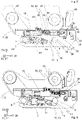
- 2 shows the main coupling part 1 in an axonometric view obliquely from below.
- the main coupling part 1 is provided for connection to the working machine and is connected to a secondary coupling part 2, cf. 3 and 4 , which is intended for connection to the attachment, can be coupled.
- the coupling of the attachment to the working machine that is mediated in this way in any case includes a mechanical coupling or fastening and can also include a hydraulic connection.
- the main coupling part 1 has a carrier device 42 with which a connection to the work machine can be established in a manner known per se, cf. figure 5 in which arms 47 of a working machine, in particular an excavator boom, are connected to the carrier device 42 - by means of bolts in corresponding bolt receptacles on the carrier device 42 and the arms 47.
- At least one load hook 44 is provided on the carrier device 42, on which, for example, slings can be hung.
- a base body 3 of the main coupling part 1 which is connected to the carrier device 42 in a manner known per se--for example by welding or screwing.
- the base body 3 extends, viewed in a longitudinal direction 7, from a first end region 8 to a second end region 9.
- the base body 3 has an open-edged insertion opening 4 (one could also speak of a receiving fork), which is used to receive a first fastening bolt 5 of the sub-coupling part 2 is used.
- the recording takes place in such a way that the fastening bolt 5 is oriented with its longitudinal axis 24 parallel to a transverse direction 22 .
- the longitudinal direction 7, the transverse direction 22 and the normal direction 23 are thereby through the Defined main coupling part 1 and are mutually normal to each other.
- the secondary coupling part 2 also has a fastening element in the form of a second fastening bolt 6, the longitudinal axis 25 of which runs parallel to the longitudinal axis 24 of the first fastening bolt 5 and is aligned with the longitudinal axis 24 in a reference plane 26 (in 3 indicated by the dashed line).
- the longitudinal axes 24, 25 run parallel to a first direction 27 and are arranged one behind the other as seen in a second direction 28.
- the second direction 28 is normal to the first direction 27 and parallel to the reference plane 26.
- the first direction 27, the second direction 28 and a third direction 29 are defined by the slave coupling part 2 and are mutually normal to each other.
- the base body 3 of the main coupling part 1 has a contact surface 10 for the fastening element or the second fastening bolt 6 .
- the contact surface 10 is correspondingly opposite the first insertion opening 4 which is open at the edge.
- first the first fastening bolt 5 is engaged with the open-edged insertion opening 4 and the contact surface 10 is engaged with the second fastening bolt 6, cf. figure 5 .
- two guide elements 43 are provided on the main coupling part 1 and protrude outwards from opposite sides of the base body 3 parallel to the transverse direction 22 .
- the sub-coupling part 2 has correspondingly shaped forks 46 which are brought into engagement with the guide elements 43 .
- a locking slide 11 is provided on the main coupling part 1, which can be moved with a main directional component parallel to the longitudinal direction 7 between a release position 12, cf. figure 5 , and a locking position 13, cf. 6 , is reciprocally movable to selectively mechanically couple and release the main clutch part 1 and the sub clutch part 2 .
- a locking direction 49 in which the locking slide 11 is moved during locking, is located.
- the locking direction 49 deviates only slightly from the longitudinal direction 7, in the exemplary embodiment shown by 4°. Ie the main directional component of the locking direction 49 or the opposite direction is parallel to the longitudinal direction 7.
- an engagement surface 16 of the locking slide 11 is arranged at least in sections opposite the contact surface 10 in the locking position 13 in order to form together with the contact surface 10 a second open-edged insertion opening 17 for receiving the second fastening bolt 6 .
- the engagement surface 16 is set up to press the second fastening bolt 6 against the contact surface 10 in the locking position 13, so that in the locking position 13 not only a form fit but also a force fit between the locking slide 11 and the second fastening bolt 6 can be achieved.
- the engagement surface 16 has a corresponding slope and/or curvature and is inclined relative to the longitudinal direction 7 in such a way that the second insertion opening 17 , which is open at the edge, widens in the longitudinal direction 7 .
- the main coupling part 1 has a hydraulic coupling unit 18—essentially block-shaped in the illustrated embodiment—with at least one hydraulic coupling 19, with five hydraulic couplings 19 being provided in the illustrated embodiment. It is provided that the hydraulic coupling unit 18 can be moved back and forth with a main directional component parallel to the longitudinal direction 7 between a decoupling position 20 and a coupling position 21, with the hydraulic coupling unit 18 being arranged behind the locking slide 11 as seen in the normal direction 23.
- a coupling direction 50 in which the hydraulic coupling unit 18 is moved for the hydraulic coupling, is drawn in.
- the coupling direction 50 is essentially parallel to the longitudinal direction 7. Ie the main directional component of the coupling direction 50 or the opposite direction is in any case parallel to the longitudinal direction 7.
- the secondary clutch part 2 accordingly also has a hydraulic clutch unit 34--essentially in the form of a block in the illustrated embodiment--with a corresponding number of hydraulic clutches 35--five in the illustrated embodiment--wherein the hydraulic clutches 35 represent counterparts to the hydraulic clutches 19, in order to, in a manner known per se, these to be connected or coupled.
- the hydraulic clutch unit 34 is arranged behind the reference plane 26 as seen in the third direction 29 . This enables the connection or coupling of the hydraulic couplings 19 and 35 when the main coupling part 1 and the sub-coupling part 2 are mechanically coupled and the Hydraulic clutch unit 18 moves into the coupling position 21. Accordingly, the connection or coupling of the hydraulic couplings 19 and 35 can be released when the main coupling part 1 and the sub-coupling part 2 are mechanically coupled and the hydraulic coupling unit 18 moves from the coupling position 21 to the uncoupling position 20 .
- a controller (not shown) for the movement of the locking slide 11 and the hydraulic coupling unit 18 is provided in the exemplary embodiment shown, which is set up for this purpose is to only move the hydraulic coupling unit 18 from the decoupling position 20 to the coupling position 21 when the locking slide 11 is in the locking position 13, and to only move the locking slide 11 from the locking position 13 to the release position 12 when the hydraulic coupling unit 18 is in the decoupling position 20.
- a hydraulic cylinder 14 is provided in the illustrated embodiment.
- the main coupling part 1 has a further hydraulic cylinder 15 which is used to move the hydraulic coupling unit 18 .
- the other hydraulic cylinder 15 is located above the hydraulic cylinder 14 or, seen in the normal direction 23, behind the hydraulic cylinder 14.
- a check valve 41 provided for the further hydraulic cylinder 15 can also be seen.
- the two hydraulic cylinders 14, 15 are actuated in the above-mentioned manner by the control, which can be designed, for example, as a hydraulic sequence control.
- the base body 3 has a guide 30 for the locking slide 11 , the locking slide 11 being accommodated at least in sections in opposite groove-shaped guide surfaces 31 of the guide 30 .
- the guide surfaces 31 are arranged in mutually opposite plate-shaped sections of the base body 3 .
- a guide 32 is provided for the hydraulic clutch unit 18, the hydraulic clutch unit 18 being accommodated at least in sections in opposite groove-shaped guide surfaces 33 of the guide 32.
- the guide surfaces 33 are also arranged in the plate-shaped sections of the base body 3 .
- the orientation of the hydraulic couplings 35 of the secondary coupling part 2 is adapted to the direction of movement of the hydraulic coupling unit 18 accordingly.
- a longitudinal axis 36 (in 3 indicated by dots) of the hydraulic clutches 35 essentially parallel to the second direction 28 or encloses an angle of zero with it.
- two tapering guide pins 40 are provided on the hydraulic coupling unit 34, which protrude from the hydraulic coupling unit 34 of the secondary coupling part 2 parallel to the longitudinal axis 36 of the hydraulic couplings 35 of the secondary coupling part 2 and pointing in the opposite direction 28.
- Corresponding recesses are provided on the hydraulic coupling unit 18 of the main coupling part 1 , into which the guide pins 40 can engage when the hydraulic coupling unit 18 moves from the decoupling position 20 into the coupling position 21 .
- the illustrated exemplary embodiment provides for the hydraulic coupling unit 34 of the secondary coupling part 2 to be elastically mounted by means of a damping plate 37 made of rubber or plastic.
- the hydraulic clutch unit 34 is in turn fastened to a bracket 48 of the secondary clutch part 2 via the damping plate 37 .
- the bracket 48 is rigidly connected to two plate-shaped sections of the secondary coupling part 2, which plate-shaped sections also have the forks 46.
- the hydraulic clutch unit 34 of the secondary clutch part 2 has five hydraulic line connections 38 which are in fluid communication with the hydraulic clutches 35 of the secondary clutch part 2 and point towards the reference plane 26, cf. 4 .
- Hydraulic lines (not shown) can be connected to the hydraulic line connections 38 of the auxiliary coupling part 2 in order to supply hydraulic drives of the add-on part with hydraulic oil.
- hydraulic line connections 38 are also provided on the main clutch part 1, which are fluidically connected to the hydraulic clutches 19 and are used to connect hydraulic lines in order to be able to provide hydraulic oil, cf. figure 5 .
- the hydraulic coupling unit 34 of the secondary coupling part 2 has two hydraulic high-flow line connections 39 which are in fluid communication with two hydraulic couplings 35 of the secondary coupling part 2 and essentially flow into the second direction 28 have.
- the high-flow hydraulic line connections 39 are carried out through the damping plate 37 and through the console 48 . Ie in the damping plate 37 and the console 48 corresponding recesses or passages for the high-flow hydraulic line connections 39 are provided.
- the direction of flow of the hydraulic oil is deflected downwards or towards the reference plane 26 or counter to the normal direction 23 and the third direction 29 by means of a hydraulic line elbow 51 in each case.
- hydraulic lines can also be connected to the hydraulic high-flow line connections 39 from "below".
- the secondary clutch part 2 has a protective plate 45 .
Landscapes
- Engineering & Computer Science (AREA)
- Mechanical Engineering (AREA)
- Mining & Mineral Resources (AREA)
- Civil Engineering (AREA)
- General Engineering & Computer Science (AREA)
- Structural Engineering (AREA)
- Hydraulic Clutches, Magnetic Clutches, Fluid Clutches, And Fluid Joints (AREA)
Priority Applications (2)
| Application Number | Priority Date | Filing Date | Title |
|---|---|---|---|
| SI201930422T SI3699362T1 (sl) | 2019-02-21 | 2019-02-21 | Sklopilni sistem za zamenljivo sklapljanje priključka z delovnim strojem |
| EP19158641.1A EP3699362B1 (de) | 2019-02-21 | 2019-02-21 | Kupplungssystem zum auswechselbaren kuppeln eines anbaugeräts mit einer arbeitsmaschine |
Applications Claiming Priority (1)
| Application Number | Priority Date | Filing Date | Title |
|---|---|---|---|
| EP19158641.1A EP3699362B1 (de) | 2019-02-21 | 2019-02-21 | Kupplungssystem zum auswechselbaren kuppeln eines anbaugeräts mit einer arbeitsmaschine |
Publications (2)
| Publication Number | Publication Date |
|---|---|
| EP3699362A1 EP3699362A1 (de) | 2020-08-26 |
| EP3699362B1 true EP3699362B1 (de) | 2022-10-05 |
Family
ID=65520186
Family Applications (1)
| Application Number | Title | Priority Date | Filing Date |
|---|---|---|---|
| EP19158641.1A Active EP3699362B1 (de) | 2019-02-21 | 2019-02-21 | Kupplungssystem zum auswechselbaren kuppeln eines anbaugeräts mit einer arbeitsmaschine |
Country Status (2)
| Country | Link |
|---|---|
| EP (1) | EP3699362B1 (sl) |
| SI (1) | SI3699362T1 (sl) |
Families Citing this family (3)
| Publication number | Priority date | Publication date | Assignee | Title |
|---|---|---|---|---|
| DE102021200268A1 (de) * | 2021-01-13 | 2022-07-14 | Kässbohrer Geländefahrzeug Aktiengesellschaft | Pistenpflegefahrzeug |
| GB2606546B (en) * | 2021-05-12 | 2023-05-17 | Caterpillar Work Tools Bv | A coupling arrangement for coupling a tool to a machine |
| US20240117603A1 (en) * | 2022-10-06 | 2024-04-11 | Caterpillar Inc. | Universal Hydraulic Connecting Quick Coupler System |
Family Cites Families (4)
| Publication number | Priority date | Publication date | Assignee | Title |
|---|---|---|---|---|
| AT410333B (de) | 2000-10-10 | 2003-03-25 | Josef Martin Gmbh & Co Kg | Anordnung zum auswechselbaren befestigen eines anbauteiles, z.b. einer baggerschaufel, an einem baggerausleger oder einem fahrzeug |
| AU2009320503C1 (en) * | 2008-11-03 | 2015-11-26 | Doherty Engineered Attachments Limited | Improvements to work attachment assemblies |
| US20110262212A1 (en) * | 2008-11-27 | 2011-10-27 | Caterpillar Work Tools B.V. | Work tool coupling arrangement |
| WO2018074937A1 (en) * | 2016-10-21 | 2018-04-26 | Doherty Engineered Attachments Limited | A coupling assembly and an attachment member comprising a coupling member |
-
2019
- 2019-02-21 SI SI201930422T patent/SI3699362T1/sl unknown
- 2019-02-21 EP EP19158641.1A patent/EP3699362B1/de active Active
Also Published As
| Publication number | Publication date |
|---|---|
| EP3699362A1 (de) | 2020-08-26 |
| SI3699362T1 (sl) | 2023-02-28 |
Similar Documents
| Publication | Publication Date | Title |
|---|---|---|
| EP1749939B1 (de) | Adapter für ein Arbeitsgerät als Teil einer Schnellwechselvorrichtung und Schnellwechselvorrichtung | |
| EP3699362B1 (de) | Kupplungssystem zum auswechselbaren kuppeln eines anbaugeräts mit einer arbeitsmaschine | |
| EP1624116B1 (de) | Hydraulikschnellkupplung | |
| EP0569026B1 (de) | Schnellwechselvorrichtung | |
| WO2008086848A1 (de) | Ventilanordnung | |
| EP1325196B1 (de) | Anordnung zum auswechselbaren befestigen eines anbauteiles, z.b. einer baggerschaufel, an einem baggerausleger oder einem fahrzeug | |
| EP3502355B1 (de) | Adapter, schnellwechsler und schnellwechselsystem | |
| EP3507421B1 (de) | Verriegelungsbolzen mit medienkupplung | |
| DE102020127481B3 (de) | Schnellwechsler mit Sperrklappe | |
| EP3730697B1 (de) | Adapter für ein schnellwechselsystem und schnellwechselsystem mit einem solchen adapter | |
| DE102020110523A1 (de) | Schnellkupplung mit Zentriervorrichtung | |
| EP3517690B1 (de) | Adapter, schnellwechsler und schnellwechselsystem | |
| EP3851404A1 (de) | Ladekranwechsler | |
| EP2152974B1 (de) | Kupplung für arbeitsmaschinen | |
| AT507598B1 (de) | Vorrichtung zum auswechselbaren aufnehmen von werkzeugen | |
| DE102019125861A1 (de) | Schnellwechsler | |
| DE102019126439A1 (de) | Arbeitsgerät, insbesondere Radlader | |
| DE19806057C2 (de) | Baumaschinenadapter | |
| DE102004015471A1 (de) | Schnellwechsler für Bagger | |
| EP0429567A1 (de) | Vorrichtung zur lösbaren kupplung von greifern oder entsprechenden werkzeugen an roboterarmen. | |
| EP1651818A1 (de) | Anordnung zum auswechselbaren befestigen eines anbauteiles, z.b. einer baggerschaufel, an einem baggerausleger oder einem fahrzeug | |
| EP4159928B1 (de) | Schnellwechsler | |
| EP3927903A1 (de) | Schnellkupplungssystem mit einem greifer als verriegelungselement | |
| DE202014102547U1 (de) | Adapter | |
| DE3701589A1 (de) | Schnellkupplung |
Legal Events
| Date | Code | Title | Description |
|---|---|---|---|
| PUAI | Public reference made under article 153(3) epc to a published international application that has entered the european phase |
Free format text: ORIGINAL CODE: 0009012 |
|
| STAA | Information on the status of an ep patent application or granted ep patent |
Free format text: STATUS: THE APPLICATION HAS BEEN PUBLISHED |
|
| AK | Designated contracting states |
Kind code of ref document: A1 Designated state(s): AL AT BE BG CH CY CZ DE DK EE ES FI FR GB GR HR HU IE IS IT LI LT LU LV MC MK MT NL NO PL PT RO RS SE SI SK SM TR |
|
| AX | Request for extension of the european patent |
Extension state: BA ME |
|
| STAA | Information on the status of an ep patent application or granted ep patent |
Free format text: STATUS: REQUEST FOR EXAMINATION WAS MADE |
|
| 17P | Request for examination filed |
Effective date: 20210223 |
|
| RBV | Designated contracting states (corrected) |
Designated state(s): AL AT BE BG CH CY CZ DE DK EE ES FI FR GB GR HR HU IE IS IT LI LT LU LV MC MK MT NL NO PL PT RO RS SE SI SK SM TR |
|
| RIN1 | Information on inventor provided before grant (corrected) |
Inventor name: ELLMAUER, GERHARD |
|
| GRAP | Despatch of communication of intention to grant a patent |
Free format text: ORIGINAL CODE: EPIDOSNIGR1 |
|
| STAA | Information on the status of an ep patent application or granted ep patent |
Free format text: STATUS: GRANT OF PATENT IS INTENDED |
|
| INTG | Intention to grant announced |
Effective date: 20220516 |
|
| GRAS | Grant fee paid |
Free format text: ORIGINAL CODE: EPIDOSNIGR3 |
|
| GRAA | (expected) grant |
Free format text: ORIGINAL CODE: 0009210 |
|
| STAA | Information on the status of an ep patent application or granted ep patent |
Free format text: STATUS: THE PATENT HAS BEEN GRANTED |
|
| AK | Designated contracting states |
Kind code of ref document: B1 Designated state(s): AL AT BE BG CH CY CZ DE DK EE ES FI FR GB GR HR HU IE IS IT LI LT LU LV MC MK MT NL NO PL PT RO RS SE SI SK SM TR |
|
| REG | Reference to a national code |
Ref country code: GB Ref legal event code: FG4D Free format text: NOT ENGLISH |
|
| REG | Reference to a national code |
Ref country code: CH Ref legal event code: EP |
|
| REG | Reference to a national code |
Ref country code: AT Ref legal event code: REF Ref document number: 1522836 Country of ref document: AT Kind code of ref document: T Effective date: 20221015 |
|
| REG | Reference to a national code |
Ref country code: DE Ref legal event code: R096 Ref document number: 502019005800 Country of ref document: DE |
|
| REG | Reference to a national code |
Ref country code: IE Ref legal event code: FG4D Free format text: LANGUAGE OF EP DOCUMENT: GERMAN |
|
| REG | Reference to a national code |
Ref country code: LT Ref legal event code: MG9D |
|
| REG | Reference to a national code |
Ref country code: NL Ref legal event code: MP Effective date: 20221005 |
|
| PG25 | Lapsed in a contracting state [announced via postgrant information from national office to epo] |
Ref country code: NL Free format text: LAPSE BECAUSE OF FAILURE TO SUBMIT A TRANSLATION OF THE DESCRIPTION OR TO PAY THE FEE WITHIN THE PRESCRIBED TIME-LIMIT Effective date: 20221005 |
|
| PG25 | Lapsed in a contracting state [announced via postgrant information from national office to epo] |
Ref country code: SE Free format text: LAPSE BECAUSE OF FAILURE TO SUBMIT A TRANSLATION OF THE DESCRIPTION OR TO PAY THE FEE WITHIN THE PRESCRIBED TIME-LIMIT Effective date: 20221005 Ref country code: PT Free format text: LAPSE BECAUSE OF FAILURE TO SUBMIT A TRANSLATION OF THE DESCRIPTION OR TO PAY THE FEE WITHIN THE PRESCRIBED TIME-LIMIT Effective date: 20230206 Ref country code: NO Free format text: LAPSE BECAUSE OF FAILURE TO SUBMIT A TRANSLATION OF THE DESCRIPTION OR TO PAY THE FEE WITHIN THE PRESCRIBED TIME-LIMIT Effective date: 20230105 Ref country code: LT Free format text: LAPSE BECAUSE OF FAILURE TO SUBMIT A TRANSLATION OF THE DESCRIPTION OR TO PAY THE FEE WITHIN THE PRESCRIBED TIME-LIMIT Effective date: 20221005 Ref country code: FI Free format text: LAPSE BECAUSE OF FAILURE TO SUBMIT A TRANSLATION OF THE DESCRIPTION OR TO PAY THE FEE WITHIN THE PRESCRIBED TIME-LIMIT Effective date: 20221005 Ref country code: ES Free format text: LAPSE BECAUSE OF FAILURE TO SUBMIT A TRANSLATION OF THE DESCRIPTION OR TO PAY THE FEE WITHIN THE PRESCRIBED TIME-LIMIT Effective date: 20221005 |
|
| PGFP | Annual fee paid to national office [announced via postgrant information from national office to epo] |
Ref country code: FR Payment date: 20230223 Year of fee payment: 5 |
|
| PG25 | Lapsed in a contracting state [announced via postgrant information from national office to epo] |
Ref country code: RS Free format text: LAPSE BECAUSE OF FAILURE TO SUBMIT A TRANSLATION OF THE DESCRIPTION OR TO PAY THE FEE WITHIN THE PRESCRIBED TIME-LIMIT Effective date: 20221005 Ref country code: PL Free format text: LAPSE BECAUSE OF FAILURE TO SUBMIT A TRANSLATION OF THE DESCRIPTION OR TO PAY THE FEE WITHIN THE PRESCRIBED TIME-LIMIT Effective date: 20221005 Ref country code: LV Free format text: LAPSE BECAUSE OF FAILURE TO SUBMIT A TRANSLATION OF THE DESCRIPTION OR TO PAY THE FEE WITHIN THE PRESCRIBED TIME-LIMIT Effective date: 20221005 Ref country code: IS Free format text: LAPSE BECAUSE OF FAILURE TO SUBMIT A TRANSLATION OF THE DESCRIPTION OR TO PAY THE FEE WITHIN THE PRESCRIBED TIME-LIMIT Effective date: 20230205 Ref country code: HR Free format text: LAPSE BECAUSE OF FAILURE TO SUBMIT A TRANSLATION OF THE DESCRIPTION OR TO PAY THE FEE WITHIN THE PRESCRIBED TIME-LIMIT Effective date: 20221005 Ref country code: GR Free format text: LAPSE BECAUSE OF FAILURE TO SUBMIT A TRANSLATION OF THE DESCRIPTION OR TO PAY THE FEE WITHIN THE PRESCRIBED TIME-LIMIT Effective date: 20230106 |
|
| P01 | Opt-out of the competence of the unified patent court (upc) registered |
Effective date: 20230426 |
|
| REG | Reference to a national code |
Ref country code: DE Ref legal event code: R097 Ref document number: 502019005800 Country of ref document: DE |
|
| PG25 | Lapsed in a contracting state [announced via postgrant information from national office to epo] |
Ref country code: SM Free format text: LAPSE BECAUSE OF FAILURE TO SUBMIT A TRANSLATION OF THE DESCRIPTION OR TO PAY THE FEE WITHIN THE PRESCRIBED TIME-LIMIT Effective date: 20221005 Ref country code: RO Free format text: LAPSE BECAUSE OF FAILURE TO SUBMIT A TRANSLATION OF THE DESCRIPTION OR TO PAY THE FEE WITHIN THE PRESCRIBED TIME-LIMIT Effective date: 20221005 Ref country code: EE Free format text: LAPSE BECAUSE OF FAILURE TO SUBMIT A TRANSLATION OF THE DESCRIPTION OR TO PAY THE FEE WITHIN THE PRESCRIBED TIME-LIMIT Effective date: 20221005 Ref country code: DK Free format text: LAPSE BECAUSE OF FAILURE TO SUBMIT A TRANSLATION OF THE DESCRIPTION OR TO PAY THE FEE WITHIN THE PRESCRIBED TIME-LIMIT Effective date: 20221005 Ref country code: CZ Free format text: LAPSE BECAUSE OF FAILURE TO SUBMIT A TRANSLATION OF THE DESCRIPTION OR TO PAY THE FEE WITHIN THE PRESCRIBED TIME-LIMIT Effective date: 20221005 |
|
| PLBE | No opposition filed within time limit |
Free format text: ORIGINAL CODE: 0009261 |
|
| STAA | Information on the status of an ep patent application or granted ep patent |
Free format text: STATUS: NO OPPOSITION FILED WITHIN TIME LIMIT |
|
| PG25 | Lapsed in a contracting state [announced via postgrant information from national office to epo] |
Ref country code: SK Free format text: LAPSE BECAUSE OF FAILURE TO SUBMIT A TRANSLATION OF THE DESCRIPTION OR TO PAY THE FEE WITHIN THE PRESCRIBED TIME-LIMIT Effective date: 20221005 Ref country code: AL Free format text: LAPSE BECAUSE OF FAILURE TO SUBMIT A TRANSLATION OF THE DESCRIPTION OR TO PAY THE FEE WITHIN THE PRESCRIBED TIME-LIMIT Effective date: 20221005 |
|
| 26N | No opposition filed |
Effective date: 20230706 |
|
| PG25 | Lapsed in a contracting state [announced via postgrant information from national office to epo] |
Ref country code: MC Free format text: LAPSE BECAUSE OF FAILURE TO SUBMIT A TRANSLATION OF THE DESCRIPTION OR TO PAY THE FEE WITHIN THE PRESCRIBED TIME-LIMIT Effective date: 20221005 |
|
| REG | Reference to a national code |
Ref country code: BE Ref legal event code: MM Effective date: 20230228 |
|
| GBPC | Gb: european patent ceased through non-payment of renewal fee |
Effective date: 20230221 |
|
| PG25 | Lapsed in a contracting state [announced via postgrant information from national office to epo] |
Ref country code: LU Free format text: LAPSE BECAUSE OF NON-PAYMENT OF DUE FEES Effective date: 20230221 |
|
| REG | Reference to a national code |
Ref country code: IE Ref legal event code: MM4A |
|
| PG25 | Lapsed in a contracting state [announced via postgrant information from national office to epo] |
Ref country code: GB Free format text: LAPSE BECAUSE OF NON-PAYMENT OF DUE FEES Effective date: 20230221 |
|
| PG25 | Lapsed in a contracting state [announced via postgrant information from national office to epo] |
Ref country code: IE Free format text: LAPSE BECAUSE OF NON-PAYMENT OF DUE FEES Effective date: 20230221 Ref country code: GB Free format text: LAPSE BECAUSE OF NON-PAYMENT OF DUE FEES Effective date: 20230221 |
|
| PG25 | Lapsed in a contracting state [announced via postgrant information from national office to epo] |
Ref country code: BE Free format text: LAPSE BECAUSE OF NON-PAYMENT OF DUE FEES Effective date: 20230228 |
|
| PGFP | Annual fee paid to national office [announced via postgrant information from national office to epo] |
Ref country code: AT Payment date: 20240207 Year of fee payment: 6 |
|
| PGFP | Annual fee paid to national office [announced via postgrant information from national office to epo] |
Ref country code: DE Payment date: 20240228 Year of fee payment: 6 Ref country code: CH Payment date: 20240301 Year of fee payment: 6 |
|
| PGFP | Annual fee paid to national office [announced via postgrant information from national office to epo] |
Ref country code: SI Payment date: 20240125 Year of fee payment: 6 |