EP3698930A1 - Weft cutting device for loom - Google Patents
Weft cutting device for loom Download PDFInfo
- Publication number
- EP3698930A1 EP3698930A1 EP20154623.1A EP20154623A EP3698930A1 EP 3698930 A1 EP3698930 A1 EP 3698930A1 EP 20154623 A EP20154623 A EP 20154623A EP 3698930 A1 EP3698930 A1 EP 3698930A1
- Authority
- EP
- European Patent Office
- Prior art keywords
- plunger
- cylinder
- hole
- cutting device
- guide
- Prior art date
- Legal status (The legal status is an assumption and is not a legal conclusion. Google has not performed a legal analysis and makes no representation as to the accuracy of the status listed.)
- Granted
Links
Images


Classifications
-
- B—PERFORMING OPERATIONS; TRANSPORTING
- B26—HAND CUTTING TOOLS; CUTTING; SEVERING
- B26D—CUTTING; DETAILS COMMON TO MACHINES FOR PERFORATING, PUNCHING, CUTTING-OUT, STAMPING-OUT OR SEVERING
- B26D5/00—Arrangements for operating and controlling machines or devices for cutting, cutting-out, stamping-out, punching, perforating, or severing by means other than cutting
- B26D5/08—Means for actuating the cutting member to effect the cut
- B26D5/12—Fluid-pressure means
-
- D—TEXTILES; PAPER
- D03—WEAVING
- D03D—WOVEN FABRICS; METHODS OF WEAVING; LOOMS
- D03D49/00—Details or constructional features not specially adapted for looms of a particular type
- D03D49/70—Devices for cutting weft threads
-
- B—PERFORMING OPERATIONS; TRANSPORTING
- B26—HAND CUTTING TOOLS; CUTTING; SEVERING
- B26D—CUTTING; DETAILS COMMON TO MACHINES FOR PERFORATING, PUNCHING, CUTTING-OUT, STAMPING-OUT OR SEVERING
- B26D1/00—Cutting through work characterised by the nature or movement of the cutting member or particular materials not otherwise provided for; Apparatus or machines therefor; Cutting members therefor
- B26D1/01—Cutting through work characterised by the nature or movement of the cutting member or particular materials not otherwise provided for; Apparatus or machines therefor; Cutting members therefor involving a cutting member which does not travel with the work
- B26D1/12—Cutting through work characterised by the nature or movement of the cutting member or particular materials not otherwise provided for; Apparatus or machines therefor; Cutting members therefor involving a cutting member which does not travel with the work having a cutting member moving about an axis
- B26D1/25—Cutting through work characterised by the nature or movement of the cutting member or particular materials not otherwise provided for; Apparatus or machines therefor; Cutting members therefor involving a cutting member which does not travel with the work having a cutting member moving about an axis with a non-circular cutting member
- B26D1/26—Cutting through work characterised by the nature or movement of the cutting member or particular materials not otherwise provided for; Apparatus or machines therefor; Cutting members therefor involving a cutting member which does not travel with the work having a cutting member moving about an axis with a non-circular cutting member moving about an axis substantially perpendicular to the line of cut
- B26D1/30—Cutting through work characterised by the nature or movement of the cutting member or particular materials not otherwise provided for; Apparatus or machines therefor; Cutting members therefor involving a cutting member which does not travel with the work having a cutting member moving about an axis with a non-circular cutting member moving about an axis substantially perpendicular to the line of cut with limited pivotal movement to effect cut
Definitions
- the present invention relates to a weft cutting device for a loom, including: a fixed blade that is fixed to a cutter holder; a movable blade that is swingably supported by the cutter holder; a shift lever that is swingably supported by the cutter holder and that is coupled to the movable blade so as to swing the movable blade by being swung; a plunger that is reciprocably contained in a cylinder formed in the cutter holder and that engages with the shift lever, the plunger swinging the shift lever by reciprocating; and an air supply device that supplies air into the cylinder to reciprocate the plunger.
- CN105803645A discloses an example of such a weft cutting device.
- the device disclosed in CN105803645A is a weft cutting device that is added to a tuck-in head (folding block) and that cuts an end portion of a weft yarn that has been beaten up.
- the weft cutting device has a cutter holder that is a main component, a fixed blade that is fixed to the cutter holder, and a movable blade that is swingably supported by the cutter holder.
- the cutter holder has a hole that functions as a cylinder, and a plunger is reciprocably contained in the cylinder.
- the cutter holder has a flow path that allows the outside of the cutter holder and an inner space of the cylinder to communicate with each other.
- the weft cutting device is configured so that the plunger reciprocates in the cylinder as air is supplied into the cylinder and as the air is discharged out of the cylinder via the flow path.
- the cylinder of the cutter holder has an opening that opens toward the outside and that communicates with the inner space.
- the weft cutting device is configured so that a part of the plunger, which is contained in the cylinder, is exposed to the outside.
- the plunger includes two plunger members (a first plunger and a second plunger).
- the weft cutting device includes a shift lever that is swingably supported by the cutter holder and that is coupled to the movable blade so as to swing the movable blade by being swung.
- the shift lever is disposed so that a part thereof extends through the opening to be located in the cylinder.
- the shift lever is engaged with the plunger in such a way that the part of the shift lever located in the cylinder is held between the two plunger members.
- a cutting operation of cutting a weft yarn that has been inserted is performed in each weaving cycle (each time the loom main shaft rotates once). In the loom, weaving is performed as the loom main shaft is rotated several hundred times per minute. Accordingly, when the device disclosed in CN105803645A is used as a weft cutting device, in the weft cutting device, the plunger is reciprocated in the cylinder several hundred times per minute.
- the weft cutting device is configured in such a way that the plunger is disposed in the cylinder so that the outer peripheral surface of the plunger is in contact with the inner peripheral surface of the cylinder, and the plunger is slidingly guided by the cylinder as the plunger reciprocates. Therefore, as the plunger reciprocates several hundred times per minute in the cylinder as described above, wear occurs between the plunger and the cylinder (cutter holder). When such wear occurs, the plunger becomes incapable of smoothly reciprocating in the cylinder. As a result, a problem in that a weft yarn is not cut at a desirable timing or a problem of a failure in cutting a weft yarn may occur.
- the weft cutting device disclosed in CN105803645A is configured in such a way that a cylindrical sleeve is fitted into the cylinder and the plunger is slidingly guided by the sleeve. Accordingly, the wear of a part of the cylinder occurs on the sleeve.
- the sleeve should be firmly secured to the cylinder (cutter holder) in order to guide the plunger that reciprocates at high speed. Accordingly, also in a case where wear occurs on the sleeve as described above, it is necessary to replace the cutter holder.
- an object of the present invention is to provide a weft cutting device for a loom, which swings a movable blade by reciprocating a plunger by supplying and discharging air as described above, the weft cutting device being capable of reducing occurrence of wear of a cylinder that may lead to high maintenance cost as described above.
- the present invention is based on a weft cutting device for a loom, the weft cutting device swinging a movable blade by reciprocating a plunger by supplying air into a cylinder as described above.
- a weft cutting device includes a guide portion that is disposed in the cylinder so as to extend in a longitudinal direction of the cylinder. Furthermore, the plunger is disposed so as to be slidingly guided by the guide portion at a guide hole that is formed parallel to the longitudinal direction in a state in which the plunger is contained in the cylinder.
- the guide hole may be a bottomed hole that opens in a pressure receiving surface, which is one end surface, of the plunger and that has a bottom surface
- the guide portion may extend from an inner end surface of the cylinder toward an inside of the cylinder, the inner end surface facing the pressure receiving surface of the plunger.
- the movable blade may be located at one swing limit of a desirable swing range in a state in which the bottom surface of the guide hole of the plunger is in contact with an end surface of the guide portion and/or a state in which the inner end surface of the cylinder and the pressure receiving surface of the plunger are in contact with each other.
- the weft cutting device may have a communication path that is formed so as to allow a space that is formed between the bottom surface of the guide hole and the end surface of the guide portion as the plunger reciprocates and an outside of the plunger to communicate with each other, and the communication path may be formed so that the space enters a negative pressure state in relation to change in a volume of the space that occurs as the plunger reciprocates and an amount of air that flows into the space due to the change in the volume.
- the weft cutting device because reciprocation of the plunger is slidingly guided by the guide portion at the guide hole formed therein, it is not necessary to form the plunger and the cylinder so that the plunger is guided along the outer peripheral surface thereof relative to the cylinder that contains the plunger. Accordingly, with the weft cutting device, it is possible to configure a cylinder portion including the plunger in such a way that the outer peripheral surface of the plunger does not contact the inner peripheral surface of the cylinder. By configuring the weft cutting device as described above, wear that occurs as the plunger reciprocates occurs only between the plunger and the guide portion.
- a component that is replaced together with the plunger due to the wear is not a cutter holder including the inner peripheral surface of the cylinder but the guide portion, which is independent from the inner peripheral surface. Therefore, the maintenance cost of using the weft cutting device can be reduced.
- the lifetime of the plunger can be prolonged.
- the volume of the space in the plunger changes as the plunger becomes displaced from a position when the movable blade is located at one swing limit of a desirable swing range, the volume of the space in the plunger changes.
- air flows into the space from the communication path as the volume of the space changes the inside of the space enters a negative pressure state, because the communication path is formed as described above.
- shock that is applied to the plunger when the movable blade reaches the other swing limit from the one swing limit is reduced, and the lifetime of the plunger can be prolonged.
- a weft cutting device 10 is added to a tuck-in head 5 and cuts a weft yarn that has been inserted so that a weft yarn having a predetermined length is tucked in.
- a loom 1 includes the tuck-in head 5, which is disposed adjacent to a woven cloth T (warp rows 2) in the weaving-width direction.
- the tuck-in head 5 folds an end portion of an inserted weft yarn into a warp shed by using an air jet.
- a tuck-in device 4, which includes the tuck-in head 5, reciprocates the tuck-in head 5 in the forward-backward directions of the loom 1 in such a way as to avoid interference with a reed 3 that swings.
- the tuck-in head 5 is attached to the other end portion of a swing arm 7 that is swingably supported by a support shaft 6 of the loom 1 at one end portion thereof. Furthermore, the tuck-in device 4 is configured so that the tuck-in head 5 is reciprocated as the swing arm 7 is swung by a driving mechanism (not shown).
- the support shaft 6, which supports the swing arm 7, is supported by a support mechanism 9 that stands on a temple bar 8 that is disposed on the loom 1 so as to extend in the weaving-width direction.
- the weft cutting device 10 is supported, together with the tuck-in head 5, by the other end portion of the swing arm 7.
- the weft cutting device 10 includes a cutter holder 14, which is a base body that supports a fixed blade 12 and a movable blade 13, and the cutter holder 14 is attached to the swing arm 7.
- the cutter holder 14 is composed of an attachment portion 14a, which has a plate-like shape and which is elongated in one direction as seen in the thickness direction thereof, and a cylinder forming portion 14b, which is disposed at one end of the attachment portion 14a in the longitudinal direction.
- the cylinder forming portion 14b has a substantially rectangular-parallelepiped shape in external appearance and has a cylinder hole 14c that contains a plunger 18.
- the cylinder hole 14c is formed so that the direction of a center line CL thereof (center line direction) coincides with the longitudinal direction of the cylinder forming portion 14b (the long-side direction of a side surface, hereafter simply referred to as "the long-side direction") and so that the cylinder hole 14c opens only in one of two end surfaces of the cylinder forming portion 14b in the long-side direction and extends in the long-side direction.
- the attachment portion 14a and the cylinder forming portion 14b are integrally formed in a state in which the long-side direction of the cylinder forming portion 14b substantially coincides with the plate-width direction of the attachment portion 14a.
- the attachment portion 14a and the cylinder forming portion 14b have a positional relationship such that one side surface of the cylinder forming portion 14b is attached to one plate surface of the attachment portion 14a. That is, as seen in the long-side direction of the cylinder forming portion 14b, the attachment portion 14a is located closer than the center of the cylinder hole 14c to one side surface of the cylinder forming portion 14b.
- the fixed blade 12 includes a blade portion 12a, which is a plate-shaped blade and has an edge 12a1 for cutting a weft yarn, and a base portion 12b, which is used to attach the fixed blade 12 to the cutter holder 14 and which is integrally formed with the blade portion 12a.
- the fixed blade 12 is formed so as to have a substantial L-shape with the base portion 12b and the blade portion 12a.
- the edge 12a1 of the blade portion 12a is formed at an inner edge of the fixed blade 12 having the L-shape.
- the base portion 12b of the fixed blade 12 is fixed to the one plate surface of the attachment portion 14a.
- the fixed blade 12 is fixed to the attachment portion 14a in a direction such that the extension direction of the blade portion 12a (the edge 12a1) is substantially perpendicular to the longitudinal direction of the attachment portion 14a and the edge 12a1 faces in a direction toward the other end of the attachment portion 14a.
- the extension direction of the blade portion 12a (the edge 12a1) of the fixed blade 12 substantially coincides with the long-side direction of the cylinder forming portion 14b, and an edge of the fixed blade 12 on the opposite side from the edge 12a1 of the blade portion 12a faces the cylinder forming portion 14b.
- a pivot shaft 15 is disposed in such a way that, in a state in which the fixed blade 12 is attached to the cutter holder 14 as described above, the pivot shaft 15 protrudes in the thickness direction of the fixed blade 12 near the boundary between the base portion 12b and the blade portion 12a of the fixed blade 12.
- the movable blade 13 is also a plate-shaped blade and has a through-hole (first through-hole, not shown) that extends through a substantially central part thereof in the thickness direction. Moreover, the movable blade 13 is formed so that a part thereof that extends beyond the first through-hole toward one end serves as a blade portion 13a having an edge 13a1. Furthermore, the movable blade 13 is swingably supported by the pivot shaft 15 in such a way that the pivot shaft 15 is inserted through the first through-hole.
- the movable blade 13 In the supported state, the movable blade 13 is in a state in which the extension direction of the blade portion 13a relative to the first through-hole is adjusted to the extension direction of the blade portion 12a of the fixed blade 12 relative to the pivot shaft 15 and the edge 13a1 of the blade portion 13a faces the fixed blade 12.
- the movable blade 13 has a through-hole (second through-hole, not shown), which extends therethrough in the thickness direction, also in a portion 13b thereof that extends beyond the first through-hole toward the other end.
- the second through-hole is formed in an end portion adjacent the other end, which is separated from the first through-hole.
- the weft cutting device 10 has a shift lever 16 for swinging the movable blade 13.
- the shift lever 16 is a lever-shaped member that has a disk-shaped portion 16a and two protruding portions 16b and 16c that protrude from the disk-shaped portion 16a in radial directions. That is, the shift lever 16 is formed so that, among the two protruding portions 16b and 16c, one protruding portion 16b corresponds to one end portion of a lever and the other protruding portion 16c corresponds to the other end portion of the lever.
- the shift lever 16 has a through-hole (third through-hole) 16a1 that extends therethrough at the center of the disk-shaped portion 16a in the thickness direction.
- the shift lever 16 has a through-hole (fourth through-hole) 16b1 also in the one end portion 16b.
- the one end portion 16b and the other end portion 16c are formed so that the extension directions (protruding directions) thereof are substantially perpendicular to each other.
- the shift lever 16 is swingably supported by the pivot shaft 15 in such a way that the pivot shaft 15 is inserted through the third through-hole 16a1. Moreover, the shift lever 16 is coupled to the movable blade 13 at the one end portion 16b.
- a coupling shaft 17 is fitted into the fourth through-hole 16b1 formed in the one end portion 16b of the shift lever 16. Furthermore, the coupling shaft 17 is fitted into the second through-hole formed in the other end portion of the movable blade 13 and is fixed in the fitted state (in a removal-prevented state), so that the one end portion 16b of the shift lever 16 and the other end portion of the movable blade 13 are coupled to each other and the shift lever 16 is coupled to the movable blade 13.
- the shift lever 16 is supported in such a way that the other end portion 16c of the lever extends toward the cylinder forming portion 14b in a state in which the shift lever 16 is coupled to the movable blade 13. That is, in a state in which the shift lever 16 is supported by the pivot shaft 15 and coupled to the movable blade 13 as described above, the other end portion 16c of the shift lever 16 extends toward the cylinder forming portion 14b of the cutter holder 14.
- the other end portion 16c has a length such that the other end portion 16c extends to the inside of the cylinder hole 14c of the cylinder forming portion 14b in this state.
- the cylinder forming portion 14b has an opening 14d that is a hole that allows the cylinder hole 14c and the outside to communicate with each other and that opens in a side surface opposite to the aforementioned one side surface and in a side surface facing the fixed blade 12. Accordingly, in a state in which the shift lever 16 is supported as described above, the weft cutting device 10 is in a state in which the other end portion 16c of the shift lever 16 is inserted into the cylinder hole 14c from the opening 14d.
- the movable blade 13 and the shift lever 16 are supported by the pivot shaft 15, which protrudes in the thickness direction from the position of the fixed blade 12 as described above.
- the movable blade 13 and the shift lever 16 are supported in this order in the protruding direction of the pivot shaft 15.
- the shift lever 16 is disposed, in the thickness direction thereof, so that the position of a plate surface of the shift lever 16 that faces the movable blade 13 substantially coincides with the position of the center of the cylinder hole 14c of the cylinder forming portion 14b.
- the other end portion 16c of the shift lever 16 extends so that the distal edge thereof is located beyond the center line CL of the cylinder hole 14c.
- the weft cutting device 10 is configured so that the other end portion 16c of the shift lever 16 and the plunger 18, which is disposed in the cylinder hole 14c of the cylinder forming portion 14b, engage with each other. Details of the configuration are as follows. In the present embodiment, it is assumed that the plunger 18 is a single member and has a groove 18e that allows the plunger 18 to engage the other end portion 16c of the shift lever 16.
- the plunger 18 is a shaft-like member having a substantially cylindrical shape.
- the outside diameter of the plunger 18 is slightly smaller than the inside diameter of the cylinder hole 14c.
- the plunger 18 has the groove 18e, which is a part for engagement described above.
- the groove 18e opens in an outer peripheral surface 18c of the plunger 18 and has two inner side surfaces 18e1 that are perpendicular to the axial direction of the plunger 18.
- the plunger 18 is contained in the cylinder hole 14c in a direction such that a bottom surface 18e2 of the groove 18e is parallel to the plate surface of the shift lever 16.
- the plunger 18 and the shift lever 16 are engaged in a state in which the other end portion 16c of the shift lever 16 is inserted into the groove 18e of the plunger 18 and two side surfaces 16c1 of the other end portion 16c are in contact with the two inner side surfaces 18e1 of the groove 18e.
- the width of the groove 18e (the distance between the two inner side surfaces 18e1) is substantially equal to the plate-width of the other end portion 16c of the shift lever 16 (the distance between the two side surfaces 16c1).
- the groove 18e has a depth such that the bottom surface 18e2 of the groove 18e is located near the axis of the plunger 18.
- the position of the bottom surface 18e2 of the groove 18e substantially coincides with the position of the plate surface the shift lever 16 on the movable blade 13 side.
- the groove 18e is formed at a position such that reciprocation of the plunger 18 is allowed even in a state in which the plunger 18 and the shift lever 16 are engaged as described above.
- the plunger 18 has a length in the axial direction such that, in a state in which one end surface 18a of the two end surfaces thereof is in contact with a bottom surface 14c1 of the cylinder hole 14c, the other end surface 18b, which is opposite to the one end surface 18a, is located closer than the opening 14d of the cylinder forming portion 14b to the opening of the cylinder hole 14c.
- a cover member 19 is attached to the cylinder forming portion 14b of the cutter holder 14 so as to close the cylinder hole 14c.
- the cover member 19 has a cover portion 19a that is substantially cylindrical, and closes the cylinder hole 14c when the cover portion 19a is attached to the cylinder forming portion 14b.
- One end portion of the cover portion 19a in the axial direction is a flange portion 19b that has larger diameter than the cylinder hole 14c.
- the other end portion of the cover portion 19a in the axial direction is an externally-threaded portion 19c that has an external thread on the outer peripheral surface thereof.
- the cylinder hole 14c has an internal thread in an inner peripheral surface 14c3 near the opening thereof.
- the cover member 19 is attached to the cylinder forming portion 14b in a state in which the externally-threaded portion 19c of the cover portion 19a is screwed into the cylinder hole 14c so that the flange portion 19b is in contact with the cylinder forming portion 14b.
- the cover member 19 has a hexagonal hole 19d that opens in an end surface 19b1 of the flange portion 19b, and a tool is inserted into the hexagonal hole 19d to screw the cover member 19 into the cylinder hole 14c.
- the cover portion 19a of the cover member 19 and the cylinder forming portion 14b form a cylinder 20 of the weft cutting device 10. Furthermore, the weft cutting device 10 includes an air supply mechanism 21 that includes an air supply device 21a that supplies compressed air into the cylinder 20 to reciprocate the plunger 18. Details of the air supply mechanism 21 are as follows.
- the dimension of the one end portion of the attachment portion 14a of the cutter holder 14 in the plate-width direction is larger than the dimension of the other end portion of the attachment portion 14a in the plate-width direction.
- the one end portion has a size such that, in the cutter holder 14 in which the attachment portion 14a and the cylinder forming portion 14b are integrally formed as described above, the one end portion exists across a region that includes a region in which the cylinder hole 14c of the cylinder forming portion 14b exists in the plate-width direction.
- the other end portion is formed, in the plate-width direction, close to the center of the one end portion. Accordingly, the attachment portion 14a is formed so that the one end portion bulges toward both sides in the plate-width direction relative to the other end portion.
- the cutter holder 14 has two air flow paths 14e and 14f that open in end surfaces of the portions (bulging portions) of the attachment portion 14a that bulge toward both sides, the air flow paths 14e and 14f communicating with the cylinder hole 14c.
- the air flow path 14e opens in the bottom surface 14c1 of the cylinder hole 14c.
- the air flow path 14f communicates with the cylinder hole 14c at a position in the vicinity of the cover portion 19a of the cover member 19 (an inner end surface 19c1 of the cylinder 20 formed by the cover portion 19a).
- the air supply device 21a is disposed on the loom 1 in such a way that the air supply device 21a is fixed to the frame (not shown) of the loom 1. Furthermore, the air supply device 21a and the cutter holder 14 (the cylinder 20) are connected via two supply tubes 21b having flexibility. The two supply tubes 21b and the cutter holder 14 are connected via two tube joints 21c, which are nipples or the like that are attached to the bulging portions of the attachment portion 14a. The supply tubes 21b connected to the cutter holder 14, the air supply device 21a, and the like constitute the air supply mechanism 21.
- the plunger 18 reciprocates in the cylinder 20 when the air supply mechanism 21 supplies compressed air into the cylinder 20 from the air flow paths 14e and 14f.
- the end surface 18a of the plunger 18 functions as a pressure receiving surface (one pressure receiving surface) and receives the pressure, and thus the plunger 18 moves forward toward the cover portion 19a.
- the other end surface 18b of the plunger 18 functions as a pressure receiving surface (the other pressure receiving surface) and receives the pressure, and thus the plunger 18 moves backward toward the bottom surface 14c1 of the cylinder hole 14c.
- the shift lever 16 which is engaged with the plunger 18, is swung.
- the movable blade 13, which is coupled to the shift lever 16, is swung across a desirable swing range.
- the weft cutting device includes a guide portion that slidingly guides a plunger.
- a guide portion 19e is a part of the cover member 19 and included in the cover member 19. Details of the guide portion 19e are as follows.
- the cover member 19 has a bar-shaped extension portion 19e that extends from an end surface 19c1 of the externally-threaded portion 19c of the cover portion 19a (an inner end surface of the cylinder 20) in the axial direction of the cover portion 19a.
- the extension portion 19e is cylindrical (round-bar shaped) and is formed at a position such that the axis thereof coincides with the axis of the cover portion 19a.
- the extension portion 19e has a length such that, in a state in which the cover member 19 is attached to the cylinder forming portion 14b as described above, an end surface 19e1 of the extension portion 19e is located at a substantial midpoint between the inner end surface 19c1 of the cylinder 20 and the bottom surface 14c1 of the cylinder hole 14c.
- the plunger 18 has an insertion hole 18f that opens only in the other pressure receiving surface 18b and into which the extension portion 19e is inserted.
- the insertion hole 18f is formed at a position such that the center thereof coincides with the axis of the plunger 18 as seen in the direction of the center line thereof.
- the insertion hole 18f has a diameter such that, in a state in which the extension portion 19e is inserted thereinto, an inner peripheral surface 18f2 thereof and an outer peripheral surface 19e2 of the extension portion 19e slidably contact each other.
- the extension portion 19e of the cover member 19 is inserted into the insertion hole 18f and the plunger 18 is supported by the extension portion 19e.
- a small gap is formed between the outer peripheral surface 18c of the plunger 18 and an inner peripheral surface 14c2 of the cylinder hole 14c.
- the insertion hole 18f is parallel to the center line direction of the cylinder hole 14c (the longitudinal direction of the cylinder 20).
- the insertion hole 18f has a depth (dimension in the axial direction of the plunger 18) such that, in a state in which the plunger 18 is in contact with the bottom surface 14c1 of the cylinder hole 14c, a bottom surface 18f1 of the insertion hole 18f and the end surface 19e1 of the extension portion 19e are separated from each other.
- the plunger 18 in a state in which the plunger 18 is supported by the extension portion 19e of the cover member 19 at the insertion hole 18f as described above, the plunger 18 is reciprocable in the longitudinal direction of the cylinder 20 and the reciprocation of the plunger 18 is slidingly guided by the extension portion 19e. Accordingly, in the weft cutting device 10, the extension portion 19e of the cover member 19 corresponds to a "guide portion" in the present invention, and the insertion hole 18f of the plunger 18 corresponds to a "guide hole”.
- the depth of the insertion hole (guide hole) 18f is such that, in a state in which the bottom surface 18f1 of the guide hole 18f and the end surface 19e1 of the guide portion 19e are in contact with each other, the other pressure receiving surface 18b of the plunger 18 is located closer than the other air flow path 14f to the opening 14d of the cylinder forming portion 14b.
- the weft cutting device 10 is configured in such a way that displacement of the plunger 18 toward the cover portion 19a is restricted by the guide portion 19e at a predetermined position so that the other air flow path 14f is not closed by the plunger.
- the cover member 19 has a through-hole 19f that extends therethrough in the axial direction of the guide portion 19e and that has a center that coincides with the axis of the guide portion 19e as seen in the axial direction thereof. Accordingly, a space (space in the plunger 18) 22 that is formed between the bottom surface 18f1 of the guide hole 18f and the end surface 19e1 of the guide portion 19e as the plunger reciprocates 18 communicates with the outside of the cylinder 20 (the outside of the plunger 18) via the through-hole 19f. Thus, the through-hole 19f functions as a "communication path".
- the communication path 19f has a diameter such that, in relation to the rate of change (change per unit time) of the volume of the space 22 in the plunger 18, the amount of air that flows into the space 22 from the communication path 19f as the plunger 18 becomes displaced toward the bottom surface 14c1 of the cylinder hole 14c is an amount that causes the space 22 to enter a negative pressure state.
- the space 22 in the plunger 18 enters a negative pressure state when the plunger 18 moves backward.
- the space 22 in the plunger 18 enters a positive pressure state when the plunger 18 moves forward.
- the movable blade 13 in a state in which the one pressure receiving surface 18a of the plunger 18 is in contact with the bottom surface 14c1 of the cylinder hole 14c, the movable blade 13 is located at one swing limit of the desirable swing range, and a cutter 11, which is composed of the movable blade 13 and the fixed blade 12, is in a maximally opened state.
- the air supply mechanism 21 starts supplying compressed air into the cylinder 20 from the one air flow path 14e
- the pressure of the compressed air is applied to the one pressure receiving surface 18a of the plunger 18, and thereby the plunger 18 starts moving forward.
- the one pressure receiving surface 18a of the plunger 18, which receives the pressure of the compressed air has a recessed portion 18d, and, when the plunger 18 starts moving forward, the plunger 18 receives the pressure of the compressed air with the recessed portion 18d.
- the plunger 18 becomes displaced toward the cover portion 19a while the plunger 18 is guided by the guide portion 19e at the guide hole 18f, and the displacement stops when the bottom surface 18f1 of the guide hole 18f contacts the end surface 19e1 of the guide portion 19e.
- the movable blade 13 swings toward the other swing limit of the swing range, and thereby the cutter 11 cuts a weft yarn.
- the air supply mechanism 21 stops supplying compressed air from the one air flow path 14e and starts supplying compressed air into the cylinder 20 from the other air flow path 14f.
- the other pressure receiving surface 18b of the plunger 18 receives the pressure of the compressed air, and the plunger 18 starts moving backward from the position where the plunger 18 has stopped as described above.
- the plunger 18 becomes displaced toward the bottom surface 14c1 of the cylinder hole 14c while being guided by the guide portion 19e, and the displacement stops when the one pressure receiving surface 18a contacts the bottom surface 14c1.
- the cutter 11 enters a maximally opened state again.
- the plunger 18 when the plunger 18 reciprocates in the cylinder 20, the plunger 18 is slidingly guided by only the guide portion 19e, which supports the plunger 18 inside of the plunger 18 (the guide hole 18f), in contrast to a general air cylinder or the like, in which the plunger 18 is supported at the outer peripheral surface 18c.
- wear does not occur on the inner peripheral surface 14c2 of the cylinder hole 14c (the cylinder forming portion 14b) of the cutter holder 14 due to the slidingly guiding.
- the guide portion 19e wears due to the slidingly guiding, the guide portion 19e is included in the cover member 19, which is removable from the cylinder forming portion 14b (the cutter holder 14) as described above. Accordingly, because a worn part can be replaced by only replacing the cover member 19 without replacing the cutter holder 14, the maintenance cost of the weft cutting device 10 can be reduced.
- the plunger 18 moves backward, although air that has been present in the space between the one pressure receiving surface 18a and the bottom surface 14c1 of the cylinder hole 14c is discharged to the outside through the gap and the outside air flows into the space 22 in the plunger 18 through the communication path 19f, the space 22 in the plunger 18 enters a negative pressure state due to the backward movement.
- the lifetime of the plunger 18 can be prolonged, because shock that is applied to the plunger 18 due to collision of the plunger 18 with the end surface 19e1 of the guide portion 19e when the plunger 18 moves forward and shock that is applied to the plunger 18 due to collision of the plunger 18 with the bottom surface 14c1 of the cylinder hole 14c when the plunger 18 moves backward are reduced.
- the present invention is not limited to the embodiment described above and may be carried out in the following modifications (1) to (6).
- the guide portion 19e has a cylindrical shape and the guide hole 18f has a diameter such that the inner peripheral surface 18f2 of the guide hole 18f and the outer peripheral surface 19e2 of the guide portion 19e slidably contact each other.
- the cross-sectional shape of the guide portion 19e and the shape of the guide hole 18f are circular shapes (substantially circular shapes).
- the cross-sectional shape of the guide portion and the shape of the guide hole are not limited to circular shapes. At least one of these shapes may be a non-circular shape.
- both of the cross-sectional shape of the guide portion and the shape of the guide hole may be the same elliptical shape or the same polygonal shape (quadrangular shape, regular hexagonal shape, or the like). These shapes need not be the same.
- the shape of the guide hole may be a substantially circular shape as with the embodiment, and the cross-sectional shape of the guide portion may be an elliptical shape or a polygonal shape that contacts the inner peripheral surface of the guide hole at two or more points on the outer periphery.
- a part of the outer peripheral surface of the guide portion that contacts the inner peripheral surface of the guide hole is an arc-shaped surface that has the same curvature as the inner peripheral surface of the guide hole.
- the cross-sectional shape of the guide portion and the shape of the guide hole differ from each other, it is not necessary that one of the shapes be circular.
- the shape of the guide hole may be an elliptical shape
- the cross-sectional shape of the guide portion may be a polygonal shape that contacts the inner peripheral surface of the guide hole at two or more corners on the outer periphery.
- a through-hole may be formed in the guide portion as in the embodiment, and the through-hole may function as a communication path.
- the communication path is not limited to a through-hole formed in the guide portion.
- the communication path may be at least one of: a groove that is formed in the guide portion so as to extend in the axial direction and open in the outer peripheral surface; and a groove that is formed in the plunger so as to extend in the direction of the center line of the guide hole and open in the inner peripheral surface of the guide hole.
- the communication path may be a through-hole that is formed in the plunger so as to open in the inner peripheral surface of the guide hole at a position closest to the bottom surface of the guide hole in the direction of the center line of the guide hole.
- the communication path is formed so that the amount of air that flows from the communication path into the space in the plunger as the plunger moves backward is an amount that causes the space to enter a negative pressure state.
- the communication path need not be formed so as to cause the space in the plunger to enter a negative pressure state due to the backward movement.
- the communication path may be formed so as to allow an amount of air corresponding to change in the volume of the space in the plunger due to the backward movement to smoothly flow into the space.
- the plunger 18 is a single member having the groove 18e, and the plunger 18 engages with the shift lever 16 at the groove 18e.
- a plunger is not limited to a single member, and may be constituted by two members (plunger constituent members) that are disposed on both sides of the other end portion of the shift lever in the center line direction of the cylinder hole.
- a plunger is formed from two plunger constituent members, each of which is a single cylindrical member, and the two plunger constituent members are disposed in the cylinder on both sides of the other end portion of the shift lever. Then, the plunger is made to engage with the shift lever by causing the other end portion of the shift lever to be held between the two plunger constituent members.
- each of the two plunger constituent members is formed so as to have a bottomed guide hole, as with the plunger 18 in the embodiment. Furthermore, a configuration that is the same as in the embodiment is used to slidingly guide reciprocation of one of the plunger constituent members, and, regarding a configuration for slidingly guiding the other plunger constituent member, a configuration similar to that for slidingly guiding the reciprocation of the one plunger constituent member may be used.
- a cylinder hole is formed in a cylinder forming portion so as to extend therethrough in the long-side direction of the cylinder forming portion.
- a cover member that is configured in a similar way to the cover member 19 in the embodiment is attached to the cylinder forming portion so as to close the cylinder hole on a side opposite from the cover member that guides reciprocation of the one plunger constituent member, in the long-side direction of the cylinder forming portion.
- the other plunger constituent member is guided at the guide hole by the guide portion of the cover member, which is attached to the cylinder forming portion as described above.
- the one air flow path may be formed so as to communicate with the cylinder hole in the vicinity of the cover portion of the cover member, as with the other air flow path.
- both of the plunger constituent members may be guided by a common guide portion.
- a cylinder hole is formed as a bottomed hole as in the embodiment, and the cylinder hole is closed by a cover member as in the embodiment.
- a guide portion of the cover member is formed so as to have has a length such that the guide portion extends in the cylinder to a position beyond the position of the other end portion of the shift lever toward the bottom surface of the cylinder hole.
- one of the plunger constituent members that is disposed on the cover portion side relative to the other end portion of the shift lever is formed so as to have a guide hole that extends therethrough in the axial direction.
- the other plunger constituent member that is disposed on the bottom surface side of the cylinder hole is formed so as to have a guide hole that is a bottomed hole as described above.
- the cylinder constituent member on the cover portion side is disposed in a state in which the guide portion is inserted into the guide hole thereof
- the cylinder constituent member on the bottom surface side is disposed in a state in which the guide portion is inserted into the guide hole thereof
- the other end portion of the shift lever is located between the two plunger constituent members.
- the guide portion has a length such that, as described above, in a state in which the end surface thereof is in contact with the bottom surface of the guide hole of the plunger constituent member on the bottom surface side, the movable blade is located at the other swing limit.
- a guide hole of the plunger constituent member on the bottom surface side may be formed as a through-hole, as with the plunger constituent member on the cover portion side.
- a groove that allows swing of the shift lever may be formed at a position in the guide portion that overlaps the shift lever.
- the other air flow path may be formed, for example, so as to open in the end surface of the cover portion.
- the one air flow path may be formed, for example, so as to open in a portion of the bottom surface of the cylinder hole that the plunger constituent member on the bottom surface side contacts.
- the guide portion 19e is an extension portion that is formed so as to extend in the axial direction in the cover portion and is formed as a single bar-shaped portion.
- the guide portion is not limited to a single extension portion as described above.
- the guide portion may be constituted by a plurality of extension portions that extend in the axial direction from a portion (cover portion) of the cover member that is attached to the cylinder forming portion. That is, in this configuration, the guide portion is constituted by the plurality of extension portions.
- the guide hole of the plunger at which the plunger is guided by the guide portion may include the same number of holes as the extension portions, or may be a single hole as in the embodiment.
- the plurality of extension portions are arranged in such a way that all of the extension portions simultaneously contact the inner peripheral surface of the guide hole.
- the guide portion 19e is integrally formed with the cover portion 19a, which is removable from the cylinder forming portion 14b. That is, in the embodiment, the guide portion 19e is formed as a part of the cover member 19 that includes the cover portion 19a and that is a part of the cylinder 20. However, in the present invention, the guide portion need not be formed as a part of the cover member. The guide portion may be formed independently from the cover member and attached to the cylinder.
- the cover member may be composed of only the cover portion.
- a member (guide-portion forming member) including a portion having a bar-like shape (bar-shaped portion) that functions as the guide portion may be formed independently from the cover member, and the guide-portion forming member may be attached to the cylinder (cover member).
- the cover member is composed of only the cover portion as described above, and the cover member has a through-hole that extends therethrough in the axial direction and into which the bar-shaped portion is fitted.
- the guide-portion forming member includes a flange portion that is formed at one end of the bar-shaped portion. Furthermore, the bar-shaped portion of the guide-portion forming member is fitted from the outside into the through-hole of the cover member, which is attached to the cylinder forming portion. By fixing the flange portion of the guide-portion forming member to the cover member, a portion of the bar-shaped portion of the guide-portion forming member on the distal end side relative to the cover portion is made to extend in the cylinder in the longitudinal direction. Thus, the portion of the bar-shaped portion that extends in the cylinder serves as the guide portion.
- the forward movement and the backward movement of the plunger 18 are respectively performed by applying the pressure of compressed air to the one pressure receiving surface 18a of the plunger 18 and to the other pressure receiving surface 18b.
- reciprocation of the plunger need not be performed in this way.
- a spring member may be interposed, in the cylinder, between the one pressure receiving surface and the bottom surface of the cylinder hole or between the other pressure receiving surface and the inner end surface of the cylinder, and one of the forward movement and the backward movement may be performed by using the urging force of the spring member.
- the present invention is applied to the weft cutting device 10 that is added to the tuck-in head 5, which is reciprocated in the forward-backward directions of the loom 1, and that swings together with the tuck-in head 5.
- a weft cutting device to which the present invention is applied is not limited to such a weft cutting device.
- the present invention may be applied to a weft cutting device that is fixedly disposed on a loom in such a way as to be added to a general tuck-in head that is fixedly disposed on the loom.
- the present invention is also applicable to a yarn supply cutter or a waste selvage cutter that is fixedly disposed on a loom in a similar way.
Landscapes
- Engineering & Computer Science (AREA)
- Life Sciences & Earth Sciences (AREA)
- Forests & Forestry (AREA)
- Mechanical Engineering (AREA)
- Textile Engineering (AREA)
- Looms (AREA)
Abstract
Description
- The present invention relates to a weft cutting device for a loom, including: a fixed blade that is fixed to a cutter holder; a movable blade that is swingably supported by the cutter holder; a shift lever that is swingably supported by the cutter holder and that is coupled to the movable blade so as to swing the movable blade by being swung; a plunger that is reciprocably contained in a cylinder formed in the cutter holder and that engages with the shift lever, the plunger swinging the shift lever by reciprocating; and an air supply device that supplies air into the cylinder to reciprocate the plunger.
-
CN105803645A discloses an example of such a weft cutting device. The device disclosed inCN105803645A is a weft cutting device that is added to a tuck-in head (folding block) and that cuts an end portion of a weft yarn that has been beaten up. - The weft cutting device has a cutter holder that is a main component, a fixed blade that is fixed to the cutter holder, and a movable blade that is swingably supported by the cutter holder. In the weft cutting device, the cutter holder has a hole that functions as a cylinder, and a plunger is reciprocably contained in the cylinder. Moreover, the cutter holder has a flow path that allows the outside of the cutter holder and an inner space of the cylinder to communicate with each other. The weft cutting device is configured so that the plunger reciprocates in the cylinder as air is supplied into the cylinder and as the air is discharged out of the cylinder via the flow path.
- The cylinder of the cutter holder has an opening that opens toward the outside and that communicates with the inner space. Thus, the weft cutting device is configured so that a part of the plunger, which is contained in the cylinder, is exposed to the outside.
- In the weft cutting device, the plunger includes two plunger members (a first plunger and a second plunger). Moreover, the weft cutting device includes a shift lever that is swingably supported by the cutter holder and that is coupled to the movable blade so as to swing the movable blade by being swung. The shift lever is disposed so that a part thereof extends through the opening to be located in the cylinder. Furthermore, the shift lever is engaged with the plunger in such a way that the part of the shift lever located in the cylinder is held between the two plunger members. With the weft cutting device configured as described above, as the plunger reciprocates in the cylinder, the shift lever, which is engaged with the plunger, swings, and thereby the movable blade swings and a cutting operation is performed.
- In general, in a loom, a cutting operation of cutting a weft yarn that has been inserted is performed in each weaving cycle (each time the loom main shaft rotates once). In the loom, weaving is performed as the loom main shaft is rotated several hundred times per minute. Accordingly, when the device disclosed in
CN105803645A is used as a weft cutting device, in the weft cutting device, the plunger is reciprocated in the cylinder several hundred times per minute. - The weft cutting device is configured in such a way that the plunger is disposed in the cylinder so that the outer peripheral surface of the plunger is in contact with the inner peripheral surface of the cylinder, and the plunger is slidingly guided by the cylinder as the plunger reciprocates. Therefore, as the plunger reciprocates several hundred times per minute in the cylinder as described above, wear occurs between the plunger and the cylinder (cutter holder). When such wear occurs, the plunger becomes incapable of smoothly reciprocating in the cylinder. As a result, a problem in that a weft yarn is not cut at a desirable timing or a problem of a failure in cutting a weft yarn may occur.
- In order to suppress occurrence of such a problem, when wear occurs as described above, it is necessary to replace the worn part. The wear occurs not only on the plunger, which reciprocates in the cylinder, but also occurs on a part of the cylinder that slidingly guides the plunger. The inventors of the present invention have found by experiment that the wear of a part of the cylinder occurs irrespective of the material of the plunger. Accordingly, if such wear occurs, it is necessary to replace the entirety of the cutter holder including the worn part of the cylinder. That is, it is necessary to replace the cutter holder, which is the main part of the weft cutting device. Therefore, use of the weft cutting device results in high maintenance cost.
- The weft cutting device disclosed in
CN105803645A is configured in such a way that a cylindrical sleeve is fitted into the cylinder and the plunger is slidingly guided by the sleeve. Accordingly, the wear of a part of the cylinder occurs on the sleeve. Although not clearly described inCN105803645A , the sleeve should be firmly secured to the cylinder (cutter holder) in order to guide the plunger that reciprocates at high speed. Accordingly, also in a case where wear occurs on the sleeve as described above, it is necessary to replace the cutter holder. - In consideration of the above circumstances, an object of the present invention is to provide a weft cutting device for a loom, which swings a movable blade by reciprocating a plunger by supplying and discharging air as described above, the weft cutting device being capable of reducing occurrence of wear of a cylinder that may lead to high maintenance cost as described above.
- The present invention is based on a weft cutting device for a loom, the weft cutting device swinging a movable blade by reciprocating a plunger by supplying air into a cylinder as described above.
- A weft cutting device according to the present invention includes a guide portion that is disposed in the cylinder so as to extend in a longitudinal direction of the cylinder. Furthermore, the plunger is disposed so as to be slidingly guided by the guide portion at a guide hole that is formed parallel to the longitudinal direction in a state in which the plunger is contained in the cylinder.
- In the weft cutting device according to the present invention, the guide hole may be a bottomed hole that opens in a pressure receiving surface, which is one end surface, of the plunger and that has a bottom surface, and the guide portion may extend from an inner end surface of the cylinder toward an inside of the cylinder, the inner end surface facing the pressure receiving surface of the plunger. Moreover, in the weft cutting device, the movable blade may be located at one swing limit of a desirable swing range in a state in which the bottom surface of the guide hole of the plunger is in contact with an end surface of the guide portion and/or a state in which the inner end surface of the cylinder and the pressure receiving surface of the plunger are in contact with each other. Furthermore, in the weft cutting device, the weft cutting device may have a communication path that is formed so as to allow a space that is formed between the bottom surface of the guide hole and the end surface of the guide portion as the plunger reciprocates and an outside of the plunger to communicate with each other, and the communication path may be formed so that the space enters a negative pressure state in relation to change in a volume of the space that occurs as the plunger reciprocates and an amount of air that flows into the space due to the change in the volume.
- With the weft cutting device according to the present invention, because reciprocation of the plunger is slidingly guided by the guide portion at the guide hole formed therein, it is not necessary to form the plunger and the cylinder so that the plunger is guided along the outer peripheral surface thereof relative to the cylinder that contains the plunger. Accordingly, with the weft cutting device, it is possible to configure a cylinder portion including the plunger in such a way that the outer peripheral surface of the plunger does not contact the inner peripheral surface of the cylinder. By configuring the weft cutting device as described above, wear that occurs as the plunger reciprocates occurs only between the plunger and the guide portion. Thus, a component that is replaced together with the plunger due to the wear is not a cutter holder including the inner peripheral surface of the cylinder but the guide portion, which is independent from the inner peripheral surface. Therefore, the maintenance cost of using the weft cutting device can be reduced.
- By forming a weft cutting device according to the present invention so that the space described above is formed in the plunger as the plunger reciprocates and so as to have the communication path so that the space enters a negative pressure state as the plunger reciprocates, the lifetime of the plunger can be prolonged. To be specific, the volume of the space in the plunger changes as the plunger becomes displaced from a position when the movable blade is located at one swing limit of a desirable swing range, the volume of the space in the plunger changes. Although air flows into the space from the communication path as the volume of the space changes, the inside of the space enters a negative pressure state, because the communication path is formed as described above. As a result, shock that is applied to the plunger when the movable blade reaches the other swing limit from the one swing limit is reduced, and the lifetime of the plunger can be prolonged.
-
-
Fig. 1 is a schematic view illustrating an example of a loom including a weft cutting device according to the present invention; -
Fig. 2 is a front view illustrating an example of a weft cutting device according to the present invention; -
Fig. 3 is a left side view ofFig. 2 ; and -
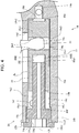
Fig. 4 is a partial enlarged sectional view of a cylinder illustrated inFig. 2 . - Hereafter, referring to
Figs. 1 to 4 , a weft cutting device according to an embodiment of the present invention will be described. In the present embodiment, aweft cutting device 10 is added to a tuck-inhead 5 and cuts a weft yarn that has been inserted so that a weft yarn having a predetermined length is tucked in. - As illustrated in
Fig. 1 , in the present embodiment, aloom 1 includes the tuck-inhead 5, which is disposed adjacent to a woven cloth T (warp rows 2) in the weaving-width direction. The tuck-inhead 5 folds an end portion of an inserted weft yarn into a warp shed by using an air jet. In the present embodiment, a tuck-indevice 4, which includes the tuck-inhead 5, reciprocates the tuck-inhead 5 in the forward-backward directions of theloom 1 in such a way as to avoid interference with a reed 3 that swings. Therefore, the tuck-inhead 5 is attached to the other end portion of a swing arm 7 that is swingably supported by asupport shaft 6 of theloom 1 at one end portion thereof. Furthermore, the tuck-indevice 4 is configured so that the tuck-inhead 5 is reciprocated as the swing arm 7 is swung by a driving mechanism (not shown). Thesupport shaft 6, which supports the swing arm 7, is supported by asupport mechanism 9 that stands on atemple bar 8 that is disposed on the loom 1 so as to extend in the weaving-width direction. - Furthermore, the
weft cutting device 10 is supported, together with the tuck-inhead 5, by the other end portion of the swing arm 7. To be specific, theweft cutting device 10 includes acutter holder 14, which is a base body that supports a fixedblade 12 and amovable blade 13, and thecutter holder 14 is attached to the swing arm 7. Regarding thecutter holder 14, to be more specific, thecutter holder 14 is composed of anattachment portion 14a, which has a plate-like shape and which is elongated in one direction as seen in the thickness direction thereof, and acylinder forming portion 14b, which is disposed at one end of theattachment portion 14a in the longitudinal direction. - The
cylinder forming portion 14b has a substantially rectangular-parallelepiped shape in external appearance and has acylinder hole 14c that contains aplunger 18. Thecylinder hole 14c is formed so that the direction of a center line CL thereof (center line direction) coincides with the longitudinal direction of thecylinder forming portion 14b (the long-side direction of a side surface, hereafter simply referred to as "the long-side direction") and so that thecylinder hole 14c opens only in one of two end surfaces of thecylinder forming portion 14b in the long-side direction and extends in the long-side direction. - In the
cutter holder 14, theattachment portion 14a and thecylinder forming portion 14b are integrally formed in a state in which the long-side direction of thecylinder forming portion 14b substantially coincides with the plate-width direction of theattachment portion 14a. Theattachment portion 14a and thecylinder forming portion 14b have a positional relationship such that one side surface of thecylinder forming portion 14b is attached to one plate surface of theattachment portion 14a. That is, as seen in the long-side direction of thecylinder forming portion 14b, theattachment portion 14a is located closer than the center of thecylinder hole 14c to one side surface of thecylinder forming portion 14b. - Regarding the fixed
blade 12 and themovable blade 13, which are supported by thecutter holder 14, the fixedblade 12 includes ablade portion 12a, which is a plate-shaped blade and has an edge 12a1 for cutting a weft yarn, and abase portion 12b, which is used to attach the fixedblade 12 to thecutter holder 14 and which is integrally formed with theblade portion 12a. The fixedblade 12 is formed so as to have a substantial L-shape with thebase portion 12b and theblade portion 12a. In the fixedblade 12, the edge 12a1 of theblade portion 12a is formed at an inner edge of the fixedblade 12 having the L-shape. - Furthermore, the
base portion 12b of the fixedblade 12 is fixed to the one plate surface of theattachment portion 14a. The fixedblade 12 is fixed to theattachment portion 14a in a direction such that the extension direction of theblade portion 12a (the edge 12a1) is substantially perpendicular to the longitudinal direction of theattachment portion 14a and the edge 12a1 faces in a direction toward the other end of theattachment portion 14a. As a result, in theweft cutting device 10, the extension direction of theblade portion 12a (the edge 12a1) of the fixedblade 12 substantially coincides with the long-side direction of thecylinder forming portion 14b, and an edge of the fixedblade 12 on the opposite side from the edge 12a1 of theblade portion 12a faces thecylinder forming portion 14b. - In the
weft cutting device 10, apivot shaft 15 is disposed in such a way that, in a state in which the fixedblade 12 is attached to thecutter holder 14 as described above, thepivot shaft 15 protrudes in the thickness direction of the fixedblade 12 near the boundary between thebase portion 12b and theblade portion 12a of the fixedblade 12. - The
movable blade 13 is also a plate-shaped blade and has a through-hole (first through-hole, not shown) that extends through a substantially central part thereof in the thickness direction. Moreover, themovable blade 13 is formed so that a part thereof that extends beyond the first through-hole toward one end serves as ablade portion 13a having an edge 13a1. Furthermore, themovable blade 13 is swingably supported by thepivot shaft 15 in such a way that thepivot shaft 15 is inserted through the first through-hole. In the supported state, themovable blade 13 is in a state in which the extension direction of theblade portion 13a relative to the first through-hole is adjusted to the extension direction of theblade portion 12a of the fixedblade 12 relative to thepivot shaft 15 and the edge 13a1 of theblade portion 13a faces the fixedblade 12. - Moreover, the
movable blade 13 has a through-hole (second through-hole, not shown), which extends therethrough in the thickness direction, also in a portion 13b thereof that extends beyond the first through-hole toward the other end. The second through-hole is formed in an end portion adjacent the other end, which is separated from the first through-hole. - The
weft cutting device 10 has ashift lever 16 for swinging themovable blade 13. Theshift lever 16 is a lever-shaped member that has a disk-shapedportion 16a and two protrudingportions portion 16a in radial directions. That is, theshift lever 16 is formed so that, among the two protrudingportions portion 16b corresponds to one end portion of a lever and the other protrudingportion 16c corresponds to the other end portion of the lever. Moreover, theshift lever 16 has a through-hole (third through-hole) 16a1 that extends therethrough at the center of the disk-shapedportion 16a in the thickness direction. Theshift lever 16 has a through-hole (fourth through-hole) 16b1 also in the oneend portion 16b. In theshift lever 16, the oneend portion 16b and theother end portion 16c are formed so that the extension directions (protruding directions) thereof are substantially perpendicular to each other. - The
shift lever 16 is swingably supported by thepivot shaft 15 in such a way that thepivot shaft 15 is inserted through the third through-hole 16a1. Moreover, theshift lever 16 is coupled to themovable blade 13 at the oneend portion 16b. To be more specific, acoupling shaft 17 is fitted into the fourth through-hole 16b1 formed in the oneend portion 16b of theshift lever 16. Furthermore, thecoupling shaft 17 is fitted into the second through-hole formed in the other end portion of themovable blade 13 and is fixed in the fitted state (in a removal-prevented state), so that the oneend portion 16b of theshift lever 16 and the other end portion of themovable blade 13 are coupled to each other and theshift lever 16 is coupled to themovable blade 13. - The
shift lever 16 is supported in such a way that theother end portion 16c of the lever extends toward thecylinder forming portion 14b in a state in which theshift lever 16 is coupled to themovable blade 13. That is, in a state in which theshift lever 16 is supported by thepivot shaft 15 and coupled to themovable blade 13 as described above, theother end portion 16c of theshift lever 16 extends toward thecylinder forming portion 14b of thecutter holder 14. Theother end portion 16c has a length such that theother end portion 16c extends to the inside of thecylinder hole 14c of thecylinder forming portion 14b in this state. - The
cylinder forming portion 14b has anopening 14d that is a hole that allows thecylinder hole 14c and the outside to communicate with each other and that opens in a side surface opposite to the aforementioned one side surface and in a side surface facing the fixedblade 12. Accordingly, in a state in which theshift lever 16 is supported as described above, theweft cutting device 10 is in a state in which theother end portion 16c of theshift lever 16 is inserted into thecylinder hole 14c from theopening 14d. - In the
weft cutting device 10, themovable blade 13 and theshift lever 16 are supported by thepivot shaft 15, which protrudes in the thickness direction from the position of the fixedblade 12 as described above. Themovable blade 13 and theshift lever 16 are supported in this order in the protruding direction of thepivot shaft 15. Furthermore, theshift lever 16 is disposed, in the thickness direction thereof, so that the position of a plate surface of theshift lever 16 that faces themovable blade 13 substantially coincides with the position of the center of thecylinder hole 14c of thecylinder forming portion 14b. Moreover, theother end portion 16c of theshift lever 16 extends so that the distal edge thereof is located beyond the center line CL of thecylinder hole 14c. - The
weft cutting device 10 is configured so that theother end portion 16c of theshift lever 16 and theplunger 18, which is disposed in thecylinder hole 14c of thecylinder forming portion 14b, engage with each other. Details of the configuration are as follows. In the present embodiment, it is assumed that theplunger 18 is a single member and has agroove 18e that allows theplunger 18 to engage theother end portion 16c of theshift lever 16. - The
plunger 18 is a shaft-like member having a substantially cylindrical shape. The outside diameter of theplunger 18 is slightly smaller than the inside diameter of thecylinder hole 14c. Moreover, theplunger 18 has thegroove 18e, which is a part for engagement described above. Thegroove 18e opens in an outerperipheral surface 18c of theplunger 18 and has two inner side surfaces 18e1 that are perpendicular to the axial direction of theplunger 18. - Furthermore, the
plunger 18 is contained in thecylinder hole 14c in a direction such that a bottom surface 18e2 of thegroove 18e is parallel to the plate surface of theshift lever 16. Theplunger 18 and theshift lever 16 are engaged in a state in which theother end portion 16c of theshift lever 16 is inserted into thegroove 18e of theplunger 18 and two side surfaces 16c1 of theother end portion 16c are in contact with the two inner side surfaces 18e1 of thegroove 18e. Accordingly, the width of thegroove 18e (the distance between the two inner side surfaces 18e1) is substantially equal to the plate-width of theother end portion 16c of the shift lever 16 (the distance between the two side surfaces 16c1). - Moreover, the
groove 18e has a depth such that the bottom surface 18e2 of thegroove 18e is located near the axis of theplunger 18. Thus, in a state in which theplunger 18 and theshift lever 16 are engaged as described above, in the thickness direction of theshift lever 16, the position of the bottom surface 18e2 of thegroove 18e substantially coincides with the position of the plate surface theshift lever 16 on themovable blade 13 side. In the axial direction of theplunger 18, thegroove 18e is formed at a position such that reciprocation of theplunger 18 is allowed even in a state in which theplunger 18 and theshift lever 16 are engaged as described above. Moreover, theplunger 18 has a length in the axial direction such that, in a state in which oneend surface 18a of the two end surfaces thereof is in contact with a bottom surface 14c1 of thecylinder hole 14c, theother end surface 18b, which is opposite to the oneend surface 18a, is located closer than theopening 14d of thecylinder forming portion 14b to the opening of thecylinder hole 14c. - A
cover member 19 is attached to thecylinder forming portion 14b of thecutter holder 14 so as to close thecylinder hole 14c. To be more specific, thecover member 19 has acover portion 19a that is substantially cylindrical, and closes thecylinder hole 14c when thecover portion 19a is attached to thecylinder forming portion 14b. One end portion of thecover portion 19a in the axial direction is aflange portion 19b that has larger diameter than thecylinder hole 14c. The other end portion of thecover portion 19a in the axial direction is an externally-threadedportion 19c that has an external thread on the outer peripheral surface thereof. Thecylinder hole 14c has an internal thread in an inner peripheral surface 14c3 near the opening thereof. Furthermore, thecover member 19 is attached to thecylinder forming portion 14b in a state in which the externally-threadedportion 19c of thecover portion 19a is screwed into thecylinder hole 14c so that theflange portion 19b is in contact with thecylinder forming portion 14b. Thecover member 19 has ahexagonal hole 19d that opens in an end surface 19b1 of theflange portion 19b, and a tool is inserted into thehexagonal hole 19d to screw thecover member 19 into thecylinder hole 14c. - The
cover portion 19a of thecover member 19 and thecylinder forming portion 14b form acylinder 20 of theweft cutting device 10. Furthermore, theweft cutting device 10 includes an air supply mechanism 21 that includes anair supply device 21a that supplies compressed air into thecylinder 20 to reciprocate theplunger 18. Details of the air supply mechanism 21 are as follows. - First, the dimension of the one end portion of the
attachment portion 14a of thecutter holder 14 in the plate-width direction is larger than the dimension of the other end portion of theattachment portion 14a in the plate-width direction. The one end portion has a size such that, in thecutter holder 14 in which theattachment portion 14a and thecylinder forming portion 14b are integrally formed as described above, the one end portion exists across a region that includes a region in which thecylinder hole 14c of thecylinder forming portion 14b exists in the plate-width direction. The other end portion is formed, in the plate-width direction, close to the center of the one end portion. Accordingly, theattachment portion 14a is formed so that the one end portion bulges toward both sides in the plate-width direction relative to the other end portion. - Furthermore, the
cutter holder 14 has twoair flow paths attachment portion 14a that bulge toward both sides, theair flow paths cylinder hole 14c. Among the twoair flow paths air flow path 14e opens in the bottom surface 14c1 of thecylinder hole 14c. Theair flow path 14f communicates with thecylinder hole 14c at a position in the vicinity of thecover portion 19a of the cover member 19 (an inner end surface 19c1 of thecylinder 20 formed by thecover portion 19a). - The
air supply device 21a is disposed on theloom 1 in such a way that theair supply device 21a is fixed to the frame (not shown) of theloom 1. Furthermore, theair supply device 21a and the cutter holder 14 (the cylinder 20) are connected via twosupply tubes 21b having flexibility. The twosupply tubes 21b and thecutter holder 14 are connected via twotube joints 21c, which are nipples or the like that are attached to the bulging portions of theattachment portion 14a. Thesupply tubes 21b connected to thecutter holder 14, theair supply device 21a, and the like constitute the air supply mechanism 21. - Furthermore, with the
weft cutting device 10 configured as described above, theplunger 18 reciprocates in thecylinder 20 when the air supply mechanism 21 supplies compressed air into thecylinder 20 from theair flow paths cylinder 20 from the oneair flow path 14e, theend surface 18a of theplunger 18 functions as a pressure receiving surface (one pressure receiving surface) and receives the pressure, and thus theplunger 18 moves forward toward thecover portion 19a. When compressed air is supplied into thecylinder 20 from the otherair flow path 14f, theother end surface 18b of theplunger 18 functions as a pressure receiving surface (the other pressure receiving surface) and receives the pressure, and thus theplunger 18 moves backward toward the bottom surface 14c1 of thecylinder hole 14c. As theplunger 18 reciprocates, theshift lever 16, which is engaged with theplunger 18, is swung. Thus, themovable blade 13, which is coupled to theshift lever 16, is swung across a desirable swing range. - In the
weft cutting device 10, according to the present invention, the weft cutting device includes a guide portion that slidingly guides a plunger. In the present embodiment, aguide portion 19e is a part of thecover member 19 and included in thecover member 19. Details of theguide portion 19e are as follows. - First, the
cover member 19 has a bar-shapedextension portion 19e that extends from an end surface 19c1 of the externally-threadedportion 19c of thecover portion 19a (an inner end surface of the cylinder 20) in the axial direction of thecover portion 19a. Theextension portion 19e is cylindrical (round-bar shaped) and is formed at a position such that the axis thereof coincides with the axis of thecover portion 19a. Moreover, theextension portion 19e has a length such that, in a state in which thecover member 19 is attached to thecylinder forming portion 14b as described above, an end surface 19e1 of theextension portion 19e is located at a substantial midpoint between the inner end surface 19c1 of thecylinder 20 and the bottom surface 14c1 of thecylinder hole 14c. - The
plunger 18 has aninsertion hole 18f that opens only in the otherpressure receiving surface 18b and into which theextension portion 19e is inserted. Theinsertion hole 18f is formed at a position such that the center thereof coincides with the axis of theplunger 18 as seen in the direction of the center line thereof. Moreover, theinsertion hole 18f has a diameter such that, in a state in which theextension portion 19e is inserted thereinto, an inner peripheral surface 18f2 thereof and an outer peripheral surface 19e2 of theextension portion 19e slidably contact each other. - Furthermore, in the
weft cutting device 10, in a state in which theplunger 18 is contained in thecylinder 20 as described above, theextension portion 19e of thecover member 19 is inserted into theinsertion hole 18f and theplunger 18 is supported by theextension portion 19e. In this state, a small gap is formed between the outerperipheral surface 18c of theplunger 18 and an inner peripheral surface 14c2 of thecylinder hole 14c. In this state, theinsertion hole 18f is parallel to the center line direction of thecylinder hole 14c (the longitudinal direction of the cylinder 20). Moreover, in order to avoid interference with reciprocation of theplunger 18 in thecylinder 20, theinsertion hole 18f has a depth (dimension in the axial direction of the plunger 18) such that, in a state in which theplunger 18 is in contact with the bottom surface 14c1 of thecylinder hole 14c, a bottom surface 18f1 of theinsertion hole 18f and the end surface 19e1 of theextension portion 19e are separated from each other. - In the
weft cutting device 10 configured as described above, in a state in which theplunger 18 is supported by theextension portion 19e of thecover member 19 at theinsertion hole 18f as described above, theplunger 18 is reciprocable in the longitudinal direction of thecylinder 20 and the reciprocation of theplunger 18 is slidingly guided by theextension portion 19e. Accordingly, in theweft cutting device 10, theextension portion 19e of thecover member 19 corresponds to a "guide portion" in the present invention, and theinsertion hole 18f of theplunger 18 corresponds to a "guide hole". - The depth of the insertion hole (guide hole) 18f is such that, in a state in which the bottom surface 18f1 of the
guide hole 18f and the end surface 19e1 of theguide portion 19e are in contact with each other, the otherpressure receiving surface 18b of theplunger 18 is located closer than the otherair flow path 14f to theopening 14d of thecylinder forming portion 14b. Thus, theweft cutting device 10 is configured in such a way that displacement of theplunger 18 toward thecover portion 19a is restricted by theguide portion 19e at a predetermined position so that the otherair flow path 14f is not closed by the plunger. - The
cover member 19 has a through-hole 19f that extends therethrough in the axial direction of theguide portion 19e and that has a center that coincides with the axis of theguide portion 19e as seen in the axial direction thereof. Accordingly, a space (space in the plunger 18) 22 that is formed between the bottom surface 18f1 of theguide hole 18f and the end surface 19e1 of theguide portion 19e as the plunger reciprocates 18 communicates with the outside of the cylinder 20 (the outside of the plunger 18) via the through-hole 19f. Thus, the through-hole 19f functions as a "communication path". Therefore, as the volume of thespace 22 changes when theplunger 18 reciprocates in thecylinder 20, air flows into thespace 22 and air flows out of thespace 22 through thecommunication path 19f. The reciprocation of theplunger 18, which changes the volume of thespace 22, is performed once for each cycle of theloom 1. - The
communication path 19f has a diameter such that, in relation to the rate of change (change per unit time) of the volume of thespace 22 in theplunger 18, the amount of air that flows into thespace 22 from thecommunication path 19f as theplunger 18 becomes displaced toward the bottom surface 14c1 of thecylinder hole 14c is an amount that causes thespace 22 to enter a negative pressure state. Thus, thespace 22 in theplunger 18 enters a negative pressure state when theplunger 18 moves backward. With this structure, thespace 22 in theplunger 18 enters a positive pressure state when theplunger 18 moves forward. - In the
weft cutting device 10 configured as described above, in a state in which the onepressure receiving surface 18a of theplunger 18 is in contact with the bottom surface 14c1 of thecylinder hole 14c, themovable blade 13 is located at one swing limit of the desirable swing range, and acutter 11, which is composed of themovable blade 13 and the fixedblade 12, is in a maximally opened state. In this state, when the air supply mechanism 21 starts supplying compressed air into thecylinder 20 from the oneair flow path 14e, the pressure of the compressed air is applied to the onepressure receiving surface 18a of theplunger 18, and thereby theplunger 18 starts moving forward. The onepressure receiving surface 18a of theplunger 18, which receives the pressure of the compressed air, has a recessedportion 18d, and, when theplunger 18 starts moving forward, theplunger 18 receives the pressure of the compressed air with the recessedportion 18d. - Subsequently, the
plunger 18 becomes displaced toward thecover portion 19a while theplunger 18 is guided by theguide portion 19e at theguide hole 18f, and the displacement stops when the bottom surface 18f1 of theguide hole 18f contacts the end surface 19e1 of theguide portion 19e. As theplunger 18 becomes displaced toward thecover portion 19a, themovable blade 13 swings toward the other swing limit of the swing range, and thereby thecutter 11 cuts a weft yarn. - Next, the air supply mechanism 21 stops supplying compressed air from the one
air flow path 14e and starts supplying compressed air into thecylinder 20 from the otherair flow path 14f. Thus, the otherpressure receiving surface 18b of theplunger 18 receives the pressure of the compressed air, and theplunger 18 starts moving backward from the position where theplunger 18 has stopped as described above. Theplunger 18 becomes displaced toward the bottom surface 14c1 of thecylinder hole 14c while being guided by theguide portion 19e, and the displacement stops when the onepressure receiving surface 18a contacts the bottom surface 14c1. As a result, thecutter 11 enters a maximally opened state again. - Thus, with the
weft cutting device 10, when theplunger 18 reciprocates in thecylinder 20, theplunger 18 is slidingly guided by only theguide portion 19e, which supports theplunger 18 inside of the plunger 18 (theguide hole 18f), in contrast to a general air cylinder or the like, in which theplunger 18 is supported at the outerperipheral surface 18c. As a result, wear does not occur on the inner peripheral surface 14c2 of thecylinder hole 14c (thecylinder forming portion 14b) of thecutter holder 14 due to the slidingly guiding. Although theguide portion 19e wears due to the slidingly guiding, theguide portion 19e is included in thecover member 19, which is removable from thecylinder forming portion 14b (the cutter holder 14) as described above. Accordingly, because a worn part can be replaced by only replacing thecover member 19 without replacing thecutter holder 14, the maintenance cost of theweft cutting device 10 can be reduced. - When the
plunger 18 moves forward, although air that has been present in the space between the otherpressure receiving surface 18b and the end surface (the inner end surface of the cylinder 20) 19c1 of thecover portion 19a is discharged to the outside through the gap between theplunger 18 and thecylinder hole 14c and air in thespace 22 in theplunger 18 is discharged to the outside through thecommunication path 19f, thespace 22 in theplunger 18 enters a positive pressure state due to the forward movement. When theplunger 18 moves backward, although air that has been present in the space between the onepressure receiving surface 18a and the bottom surface 14c1 of thecylinder hole 14c is discharged to the outside through the gap and the outside air flows into thespace 22 in theplunger 18 through thecommunication path 19f, thespace 22 in theplunger 18 enters a negative pressure state due to the backward movement. Thus, the lifetime of theplunger 18 can be prolonged, because shock that is applied to theplunger 18 due to collision of theplunger 18 with the end surface 19e1 of theguide portion 19e when theplunger 18 moves forward and shock that is applied to theplunger 18 due to collision of theplunger 18 with the bottom surface 14c1 of thecylinder hole 14c when theplunger 18 moves backward are reduced. - The present invention is not limited to the embodiment described above and may be carried out in the following modifications (1) to (6).
- (1) Regarding a guide portion for guiding reciprocation of a plunger and a guide hole in the plunger, in the embodiment, the
guide portion 19e has a cylindrical shape and theguide hole 18f has a diameter such that the inner peripheral surface 18f2 of theguide hole 18f and the outer peripheral surface 19e2 of theguide portion 19e slidably contact each other. That is, in the embodiment, the cross-sectional shape of theguide portion 19e and the shape of theguide hole 18f are circular shapes (substantially circular shapes). However, in the present invention, the cross-sectional shape of the guide portion and the shape of the guide hole are not limited to circular shapes. At least one of these shapes may be a non-circular shape. - For example, both of the cross-sectional shape of the guide portion and the shape of the guide hole may be the same elliptical shape or the same polygonal shape (quadrangular shape, regular hexagonal shape, or the like). These shapes need not be the same. For example, the shape of the guide hole may be a substantially circular shape as with the embodiment, and the cross-sectional shape of the guide portion may be an elliptical shape or a polygonal shape that contacts the inner peripheral surface of the guide hole at two or more points on the outer periphery. In this case, in order to make the contact area larger, preferably, a part of the outer peripheral surface of the guide portion that contacts the inner peripheral surface of the guide hole is an arc-shaped surface that has the same curvature as the inner peripheral surface of the guide hole. Moreover, in the case where the cross-sectional shape of the guide portion and the shape of the guide hole differ from each other, it is not necessary that one of the shapes be circular. For example, the shape of the guide hole may be an elliptical shape, and the cross-sectional shape of the guide portion may be a polygonal shape that contacts the inner peripheral surface of the guide hole at two or more corners on the outer periphery.
- In the configuration in which the cross-sectional shape of the guide portion and the shape of the guide hole differ from each other as described above, there are a plurality of spaces between the outer peripheral surface of the guide portion and the inner peripheral surface of the guide hole. The spaces communicate with a space that is formed between the end surface of the guide portion and the bottom surface of the guide hole as the plunger reciprocates, and communicates with a space between the plunger and the cover portion (the outside of the plunger). Accordingly, because the plurality of spaces around the guide portion can function as communication paths, in this configuration, it is not necessary to form a through-hole, which functions as a communication path, in the guide portion (cover member) as in the embodiment.
- On the other hand, in the configuration in which the cross-sectional shape of the guide portion and the shape of the guide hole are the same shape as described above, a through-hole may be formed in the guide portion as in the embodiment, and the through-hole may function as a communication path. However, in the case where the cross-sectional shape of the guide portion and the shape of the guide hole are the same shape as in the embodiment and in this configuration, the communication path is not limited to a through-hole formed in the guide portion. The communication path may be at least one of: a groove that is formed in the guide portion so as to extend in the axial direction and open in the outer peripheral surface; and a groove that is formed in the plunger so as to extend in the direction of the center line of the guide hole and open in the inner peripheral surface of the guide hole. In the case where the cross-sectional shape of the guide portion and the shape of the guide hole are the same shape, the communication path may be a through-hole that is formed in the plunger so as to open in the inner peripheral surface of the guide hole at a position closest to the bottom surface of the guide hole in the direction of the center line of the guide hole.
- Furthermore, regarding the communication path described above, preferably, as with the embodiment, the communication path is formed so that the amount of air that flows from the communication path into the space in the plunger as the plunger moves backward is an amount that causes the space to enter a negative pressure state. However, in the present invention, the communication path need not be formed so as to cause the space in the plunger to enter a negative pressure state due to the backward movement. The communication path may be formed so as to allow an amount of air corresponding to change in the volume of the space in the plunger due to the backward movement to smoothly flow into the space.
- (2) Regarding the plunger as a constituent element that swings the shift lever, in the embodiment, the
plunger 18 is a single member having thegroove 18e, and theplunger 18 engages with theshift lever 16 at thegroove 18e. However, in the present invention, a plunger is not limited to a single member, and may be constituted by two members (plunger constituent members) that are disposed on both sides of the other end portion of the shift lever in the center line direction of the cylinder hole. - To be specific, a plunger is formed from two plunger constituent members, each of which is a single cylindrical member, and the two plunger constituent members are disposed in the cylinder on both sides of the other end portion of the shift lever. Then, the plunger is made to engage with the shift lever by causing the other end portion of the shift lever to be held between the two plunger constituent members.
- In the case where the plunger is constituted by the two plunger constituent member in this way, it is necessary that reciprocation of each of the two plunger constituent members be guided by the guide portion. Therefore, for example, each of the two plunger constituent members is formed so as to have a bottomed guide hole, as with the
plunger 18 in the embodiment. Furthermore, a configuration that is the same as in the embodiment is used to slidingly guide reciprocation of one of the plunger constituent members, and, regarding a configuration for slidingly guiding the other plunger constituent member, a configuration similar to that for slidingly guiding the reciprocation of the one plunger constituent member may be used. - Regarding the configuration for slidingly guiding reciprocation of the other plunger constituent member, to be specific, a cylinder hole is formed in a cylinder forming portion so as to extend therethrough in the long-side direction of the cylinder forming portion. A cover member that is configured in a similar way to the
cover member 19 in the embodiment is attached to the cylinder forming portion so as to close the cylinder hole on a side opposite from the cover member that guides reciprocation of the one plunger constituent member, in the long-side direction of the cylinder forming portion. Furthermore, the other plunger constituent member is guided at the guide hole by the guide portion of the cover member, which is attached to the cylinder forming portion as described above. In this configuration, the one air flow path may be formed so as to communicate with the cylinder hole in the vicinity of the cover portion of the cover member, as with the other air flow path. - In the case where the plunger includes two plunger constituent members, both of the plunger constituent members may be guided by a common guide portion. To be specific, a cylinder hole is formed as a bottomed hole as in the embodiment, and the cylinder hole is closed by a cover member as in the embodiment. A guide portion of the cover member is formed so as to have has a length such that the guide portion extends in the cylinder to a position beyond the position of the other end portion of the shift lever toward the bottom surface of the cylinder hole.
- Regarding the two plunger constituent members, one of the plunger constituent members that is disposed on the cover portion side relative to the other end portion of the shift lever is formed so as to have a guide hole that extends therethrough in the axial direction. On the other hand, the other plunger constituent member that is disposed on the bottom surface side of the cylinder hole is formed so as to have a guide hole that is a bottomed hole as described above. Furthermore, for example, the cylinder constituent member on the cover portion side is disposed in a state in which the guide portion is inserted into the guide hole thereof, the cylinder constituent member on the bottom surface side is disposed in a state in which the guide portion is inserted into the guide hole thereof, and the other end portion of the shift lever is located between the two plunger constituent members. Regarding the guide portion, the guide portion has a length such that, as described above, in a state in which the end surface thereof is in contact with the bottom surface of the guide hole of the plunger constituent member on the bottom surface side, the movable blade is located at the other swing limit.
- In the configuration in which the two plunger constituent members are guided by a single guide portion in this way, a guide hole of the plunger constituent member on the bottom surface side may be formed as a through-hole, as with the plunger constituent member on the cover portion side.
- In these configurations, because the guide portion passes through a region in the cylinder where the shift lever is present, it is necessary that the guide portion and/or the shift lever be configured so that these do not interfere with each other. As such a configuration, for example, a groove that allows swing of the shift lever may be formed at a position in the guide portion that overlaps the shift lever.
- In these configurations, displacement of the plunger constituent member on the cover portion side during the forward movement is stopped when the inner end surface of the cylinder (the end surface of the cover portion) contacts the pressure receiving surface of the plunger constituent member. In this case, if the other air flow path is formed at a position as in the embodiment, compressed air from the air flow path is mistakenly supplied toward the outer peripheral surface of the plunger constituent member. Therefore, the other air flow path may be formed, for example, so as to open in the end surface of the cover portion. In the case where the guide hole of the plunger constituent member on the bottom surface side is formed as a through-hole as described above, the one air flow path may be formed, for example, so as to open in a portion of the bottom surface of the cylinder hole that the plunger constituent member on the bottom surface side contacts.
- (3) Regarding the guide portion that slidingly guides the plunger, in the embodiment, the
guide portion 19e is an extension portion that is formed so as to extend in the axial direction in the cover portion and is formed as a single bar-shaped portion. However, in the present invention, the guide portion is not limited to a single extension portion as described above. The guide portion may be constituted by a plurality of extension portions that extend in the axial direction from a portion (cover portion) of the cover member that is attached to the cylinder forming portion. That is, in this configuration, the guide portion is constituted by the plurality of extension portions. - In the case where the guide portion is constituted by the plurality of extension portions, the guide hole of the plunger at which the plunger is guided by the guide portion may include the same number of holes as the extension portions, or may be a single hole as in the embodiment. In the case where the guide hole is a single hole, the plurality of extension portions are arranged in such a way that all of the extension portions simultaneously contact the inner peripheral surface of the guide hole.
- (4) Regarding the guide portion that slidingly guides the plunger, in the embodiment, the
guide portion 19e is integrally formed with thecover portion 19a, which is removable from thecylinder forming portion 14b. That is, in the embodiment, theguide portion 19e is formed as a part of thecover member 19 that includes thecover portion 19a and that is a part of thecylinder 20. However, in the present invention, the guide portion need not be formed as a part of the cover member. The guide portion may be formed independently from the cover member and attached to the cylinder. - To be more specific, the cover member may be composed of only the cover portion. Furthermore, regarding the guide portion, a member (guide-portion forming member) including a portion having a bar-like shape (bar-shaped portion) that functions as the guide portion may be formed independently from the cover member, and the guide-portion forming member may be attached to the cylinder (cover member).
- As such a configuration, for example, the cover member is composed of only the cover portion as described above, and the cover member has a through-hole that extends therethrough in the axial direction and into which the bar-shaped portion is fitted. The guide-portion forming member includes a flange portion that is formed at one end of the bar-shaped portion. Furthermore, the bar-shaped portion of the guide-portion forming member is fitted from the outside into the through-hole of the cover member, which is attached to the cylinder forming portion. By fixing the flange portion of the guide-portion forming member to the cover member, a portion of the bar-shaped portion of the guide-portion forming member on the distal end side relative to the cover portion is made to extend in the cylinder in the longitudinal direction. Thus, the portion of the bar-shaped portion that extends in the cylinder serves as the guide portion.
- (5) Regarding a configuration for reciprocating the plunger, in the embodiment, the forward movement and the backward movement of the
plunger 18 are respectively performed by applying the pressure of compressed air to the onepressure receiving surface 18a of theplunger 18 and to the otherpressure receiving surface 18b. However, in the present invention, reciprocation of the plunger need not be performed in this way. A spring member may be interposed, in the cylinder, between the one pressure receiving surface and the bottom surface of the cylinder hole or between the other pressure receiving surface and the inner end surface of the cylinder, and one of the forward movement and the backward movement may be performed by using the urging force of the spring member. - (6) Regarding a weft cutting device to which the present invention is applied, in the embodiment, the present invention is applied to the
weft cutting device 10 that is added to the tuck-inhead 5, which is reciprocated in the forward-backward directions of theloom 1, and that swings together with the tuck-inhead 5. However, a weft cutting device to which the present invention is applied is not limited to such a weft cutting device. For example, the present invention may be applied to a weft cutting device that is fixedly disposed on a loom in such a way as to be added to a general tuck-in head that is fixedly disposed on the loom. Moreover, the present invention is also applicable to a yarn supply cutter or a waste selvage cutter that is fixedly disposed on a loom in a similar way. - The present invention is not limited to the embodiment described above and may be modified in various ways within the spirit and scope of the present invention.
Claims (2)
- A weft cutting device (10) for a loom (1), comprising:a fixed blade (12) that is fixed to a cutter holder (14);a movable blade (13) that is swingably supported by the cutter holder (14);a shift lever (16) that is swingably supported by the cutter holder (14) and that is coupled to the movable blade (13) so as to swing the movable blade (13) by being swung;a plunger (18) that is reciprocably contained in a cylinder (20) formed in the cutter holder (14) and that engages with the shift lever (16), the plunger (18) swinging the shift lever (16) by reciprocating; andan air supply device (21a) that supplies air into the cylinder (20) to reciprocate the plunger (18),wherein the weft cutting device (10) includes a guide portion (19e) that is disposed in the cylinder (20) so as to extend in a longitudinal direction of the cylinder (20), andwherein the plunger (18) is disposed so as to be slidingly guided by the guide portion (19e) at a guide hole (18f) that is formed parallel to the longitudinal direction in a state in which the plunger (18) is contained in the cylinder (20).
- The weft cutting device (10) for a loom (1) according to Claim 1,
wherein the guide hole (18f) is a bottomed hole that opens in a pressure receiving surface (18b), which is one end surface, of the plunger (18) and that has a bottom surface (18f1),
wherein the guide portion (19e) extends from an inner end surface (19c1) of the cylinder (20) toward an inside of the cylinder (20), the inner end surface (19c1) facing the pressure receiving surface (18b) of the plunger (18),
wherein the movable blade (13) is located at one swing limit of a desirable swing range in a state in which the bottom surface (18f1) of the guide hole (18f) of the plunger (18) is in contact with an end surface (19e1) of the guide portion (19e) and/or in a state in which the inner end surface (19c1) of the cylinder (20) and the pressure receiving surface (18b) of the plunger (18) are in contact with each other,
wherein the weft cutting device (10) has a communication path (19f) that is formed so as to allow a space (22) that is formed between the bottom surface (18f1) of the guide hole (18f) and the end surface (19e1) of the guide portion (19e) as the plunger (18) reciprocates and an outside of the plunger (18) to communicate with each other, and
wherein the communication path (19f) is formed so that the space (22) enters a negative pressure state in relation to change in a volume of the space (22) that occurs as the plunger (18) reciprocates and an amount of air that flows into the space (22) due to the change in the volume.
Applications Claiming Priority (1)
| Application Number | Priority Date | Filing Date | Title |
|---|---|---|---|
| JP2019027385A JP7256025B2 (en) | 2019-02-19 | 2019-02-19 | Weft cutting device in loom |
Publications (2)
| Publication Number | Publication Date |
|---|---|
| EP3698930A1 true EP3698930A1 (en) | 2020-08-26 |
| EP3698930B1 EP3698930B1 (en) | 2021-12-08 |
Family
ID=69411333
Family Applications (1)
| Application Number | Title | Priority Date | Filing Date |
|---|---|---|---|
| EP20154623.1A Active EP3698930B1 (en) | 2019-02-19 | 2020-01-30 | Weft cutting device for loom |
Country Status (3)
| Country | Link |
|---|---|
| EP (1) | EP3698930B1 (en) |
| JP (1) | JP7256025B2 (en) |
| CN (1) | CN111575882B (en) |
Citations (3)
| Publication number | Priority date | Publication date | Assignee | Title |
|---|---|---|---|---|
| CN100548599C (en) * | 2006-09-14 | 2009-10-14 | 江苏华宏科技股份有限公司 | The Foot control mechanism of hydraulic shearer |
| CN105803645A (en) | 2016-05-06 | 2016-07-27 | 山东日发纺织机械有限公司 | Pneumatic scissor and fold selvage device |
| CN107932804A (en) * | 2017-12-23 | 2018-04-20 | 无锡市创恒机械有限公司 | Utilize the cutting mechanism of small cylinder |
Family Cites Families (8)
| Publication number | Priority date | Publication date | Assignee | Title |
|---|---|---|---|---|
| JPH0616953Y2 (en) * | 1988-06-07 | 1994-05-02 | 株式会社豊田自動織機製作所 | Weft cutting device for loom |
| JPH0852Y2 (en) * | 1989-02-02 | 1996-01-10 | 花園工具株式会社 | Pneumatic tool |
| DE4020030A1 (en) * | 1990-06-23 | 1992-01-09 | Dornier Gmbh Lindauer | Weft shear for loom - has independent drive mechanism, allowing pneumatically driven shear blade to act independently of loom motion |
| IT1269801B (en) * | 1994-05-20 | 1997-04-15 | Nuovo Pignone Spa | IMPROVED WEFT CUTTER FOR AIR FRAME |
| BE1017684A3 (en) * | 2007-07-12 | 2009-03-03 | Picanol Nv | METHOD FOR INSERTING AN END OF A WELDING THREAD INTO A SIDE OF A TISSUE AND A PNEUMATIC EDGE INSERT. |
| CN205775111U (en) * | 2016-05-06 | 2016-12-07 | 山东日发纺织机械有限公司 | A kind of pneumatic scissors being applied to middle framing loom and Tucked-in selvage apparatus |
| CN105780272A (en) | 2016-05-06 | 2016-07-20 | 山东日发纺织机械有限公司 | Pneumatic scissors and selvage folding device used in medium width loom |
| CN106757699B (en) * | 2017-01-19 | 2019-08-13 | 青岛天一红旗纺机集团有限公司 | A kind of direct-connected pneumatic optical margin device of slay |
-
2019
- 2019-02-19 JP JP2019027385A patent/JP7256025B2/en active Active
-
2020
- 2020-01-30 EP EP20154623.1A patent/EP3698930B1/en active Active
- 2020-01-31 CN CN202010077707.8A patent/CN111575882B/en active Active
Patent Citations (3)
| Publication number | Priority date | Publication date | Assignee | Title |
|---|---|---|---|---|
| CN100548599C (en) * | 2006-09-14 | 2009-10-14 | 江苏华宏科技股份有限公司 | The Foot control mechanism of hydraulic shearer |
| CN105803645A (en) | 2016-05-06 | 2016-07-27 | 山东日发纺织机械有限公司 | Pneumatic scissor and fold selvage device |
| CN107932804A (en) * | 2017-12-23 | 2018-04-20 | 无锡市创恒机械有限公司 | Utilize the cutting mechanism of small cylinder |
Also Published As
| Publication number | Publication date |
|---|---|
| EP3698930B1 (en) | 2021-12-08 |
| CN111575882B (en) | 2023-04-07 |
| JP2020133042A (en) | 2020-08-31 |
| JP7256025B2 (en) | 2023-04-11 |
| CN111575882A (en) | 2020-08-25 |
Similar Documents
| Publication | Publication Date | Title |
|---|---|---|
| EP3698930B1 (en) | Weft cutting device for loom | |
| US4858548A (en) | Needle bar and feed drives for a zig-zag sewing machine | |
| CN107020425B (en) | Electrode wire threading device for electric spark wire etching machine | |
| EP0683256A1 (en) | Weft cutter for air loom | |
| US4993152A (en) | Dry-shaving apparatus | |
| KR101090216B1 (en) | Sewing machine with thread cutting device | |
| JP6558957B2 (en) | Fishing reel reciprocating mechanism | |
| JP4718248B2 (en) | Ear weaving device | |
| JP2007512441A (en) | Yarn control device for textile machines, especially for opening devices | |
| JP4371928B2 (en) | Sewing machine looper drive | |
| CN111286885B (en) | Independent engraving hole system for embroidery machine | |
| KR20080074747A (en) | Sewing machine with thread breaker | |
| EP3650594B1 (en) | Air jet loom with air tuck-in device | |
| CN114753068B (en) | Switch needle bar sewing machine | |
| JP4601035B2 (en) | Weft insertion device for water jet loom | |
| TWM579656U (en) | Thread cutting device of column-tube type sewing machine | |
| EP3483318B1 (en) | Weft insertion device for rapier loom | |
| CN215964464U (en) | Hit needle valve, go out gluey module and go out gluey equipment | |
| CN108893842B (en) | Pneumatic selvedge folding device of rapier loom | |
| JP2007247082A (en) | Nozzle for cleaning cutter blade of yarn feeding cutter | |
| JP2022173636A (en) | Selvage shedding device for loom | |
| CN117480290B (en) | Clamps for rapier looms | |
| KR200166328Y1 (en) | Cutting machine of a brush wire | |
| CN112323273A (en) | Thread trimming mechanism of sewing machine | |
| CN218796967U (en) | Coating mechanism and PCB processing equipment |
Legal Events
| Date | Code | Title | Description |
|---|---|---|---|
| PUAI | Public reference made under article 153(3) epc to a published international application that has entered the european phase |
Free format text: ORIGINAL CODE: 0009012 |
|
| STAA | Information on the status of an ep patent application or granted ep patent |
Free format text: STATUS: THE APPLICATION HAS BEEN PUBLISHED |
|
| AK | Designated contracting states |
Kind code of ref document: A1 Designated state(s): AL AT BE BG CH CY CZ DE DK EE ES FI FR GB GR HR HU IE IS IT LI LT LU LV MC MK MT NL NO PL PT RO RS SE SI SK SM TR |
|
| AX | Request for extension of the european patent |
Extension state: BA ME |
|
| STAA | Information on the status of an ep patent application or granted ep patent |
Free format text: STATUS: REQUEST FOR EXAMINATION WAS MADE |
|
| 17P | Request for examination filed |
Effective date: 20210204 |
|
| RBV | Designated contracting states (corrected) |
Designated state(s): AL AT BE BG CH CY CZ DE DK EE ES FI FR GB GR HR HU IE IS IT LI LT LU LV MC MK MT NL NO PL PT RO RS SE SI SK SM TR |
|
| GRAP | Despatch of communication of intention to grant a patent |
Free format text: ORIGINAL CODE: EPIDOSNIGR1 |
|
| STAA | Information on the status of an ep patent application or granted ep patent |
Free format text: STATUS: GRANT OF PATENT IS INTENDED |
|
| RIC1 | Information provided on ipc code assigned before grant |
Ipc: B26D 1/30 20060101AFI20210528BHEP Ipc: B26D 5/12 20060101ALI20210528BHEP |
|
| INTG | Intention to grant announced |
Effective date: 20210618 |
|
| GRAS | Grant fee paid |
Free format text: ORIGINAL CODE: EPIDOSNIGR3 |
|
| GRAA | (expected) grant |
Free format text: ORIGINAL CODE: 0009210 |
|
| STAA | Information on the status of an ep patent application or granted ep patent |
Free format text: STATUS: THE PATENT HAS BEEN GRANTED |
|
| AK | Designated contracting states |
Kind code of ref document: B1 Designated state(s): AL AT BE BG CH CY CZ DE DK EE ES FI FR GB GR HR HU IE IS IT LI LT LU LV MC MK MT NL NO PL PT RO RS SE SI SK SM TR |
|
| REG | Reference to a national code |
Ref country code: GB Ref legal event code: FG4D |
|
| REG | Reference to a national code |
Ref country code: AT Ref legal event code: REF Ref document number: 1453408 Country of ref document: AT Kind code of ref document: T Effective date: 20211215 Ref country code: CH Ref legal event code: EP |
|
| REG | Reference to a national code |
Ref country code: DE Ref legal event code: R096 Ref document number: 602020001181 Country of ref document: DE |
|
| REG | Reference to a national code |
Ref country code: IE Ref legal event code: FG4D |
|
| REG | Reference to a national code |
Ref country code: LT Ref legal event code: MG9D |
|
| REG | Reference to a national code |
Ref country code: NL Ref legal event code: MP Effective date: 20211208 |
|
| PG25 | Lapsed in a contracting state [announced via postgrant information from national office to epo] |
Ref country code: RS Free format text: LAPSE BECAUSE OF FAILURE TO SUBMIT A TRANSLATION OF THE DESCRIPTION OR TO PAY THE FEE WITHIN THE PRESCRIBED TIME-LIMIT Effective date: 20211208 Ref country code: LT Free format text: LAPSE BECAUSE OF FAILURE TO SUBMIT A TRANSLATION OF THE DESCRIPTION OR TO PAY THE FEE WITHIN THE PRESCRIBED TIME-LIMIT Effective date: 20211208 Ref country code: FI Free format text: LAPSE BECAUSE OF FAILURE TO SUBMIT A TRANSLATION OF THE DESCRIPTION OR TO PAY THE FEE WITHIN THE PRESCRIBED TIME-LIMIT Effective date: 20211208 Ref country code: BG Free format text: LAPSE BECAUSE OF FAILURE TO SUBMIT A TRANSLATION OF THE DESCRIPTION OR TO PAY THE FEE WITHIN THE PRESCRIBED TIME-LIMIT Effective date: 20220308 |
|
| REG | Reference to a national code |
Ref country code: AT Ref legal event code: MK05 Ref document number: 1453408 Country of ref document: AT Kind code of ref document: T Effective date: 20211208 |
|
| PG25 | Lapsed in a contracting state [announced via postgrant information from national office to epo] |
Ref country code: SE Free format text: LAPSE BECAUSE OF FAILURE TO SUBMIT A TRANSLATION OF THE DESCRIPTION OR TO PAY THE FEE WITHIN THE PRESCRIBED TIME-LIMIT Effective date: 20211208 Ref country code: NO Free format text: LAPSE BECAUSE OF FAILURE TO SUBMIT A TRANSLATION OF THE DESCRIPTION OR TO PAY THE FEE WITHIN THE PRESCRIBED TIME-LIMIT Effective date: 20220308 Ref country code: LV Free format text: LAPSE BECAUSE OF FAILURE TO SUBMIT A TRANSLATION OF THE DESCRIPTION OR TO PAY THE FEE WITHIN THE PRESCRIBED TIME-LIMIT Effective date: 20211208 Ref country code: HR Free format text: LAPSE BECAUSE OF FAILURE TO SUBMIT A TRANSLATION OF THE DESCRIPTION OR TO PAY THE FEE WITHIN THE PRESCRIBED TIME-LIMIT Effective date: 20211208 Ref country code: GR Free format text: LAPSE BECAUSE OF FAILURE TO SUBMIT A TRANSLATION OF THE DESCRIPTION OR TO PAY THE FEE WITHIN THE PRESCRIBED TIME-LIMIT Effective date: 20220309 |
|
| PG25 | Lapsed in a contracting state [announced via postgrant information from national office to epo] |
Ref country code: NL Free format text: LAPSE BECAUSE OF FAILURE TO SUBMIT A TRANSLATION OF THE DESCRIPTION OR TO PAY THE FEE WITHIN THE PRESCRIBED TIME-LIMIT Effective date: 20211208 |
|
| PG25 | Lapsed in a contracting state [announced via postgrant information from national office to epo] |
Ref country code: SM Free format text: LAPSE BECAUSE OF FAILURE TO SUBMIT A TRANSLATION OF THE DESCRIPTION OR TO PAY THE FEE WITHIN THE PRESCRIBED TIME-LIMIT Effective date: 20211208 Ref country code: SK Free format text: LAPSE BECAUSE OF FAILURE TO SUBMIT A TRANSLATION OF THE DESCRIPTION OR TO PAY THE FEE WITHIN THE PRESCRIBED TIME-LIMIT Effective date: 20211208 Ref country code: RO Free format text: LAPSE BECAUSE OF FAILURE TO SUBMIT A TRANSLATION OF THE DESCRIPTION OR TO PAY THE FEE WITHIN THE PRESCRIBED TIME-LIMIT Effective date: 20211208 Ref country code: PT Free format text: LAPSE BECAUSE OF FAILURE TO SUBMIT A TRANSLATION OF THE DESCRIPTION OR TO PAY THE FEE WITHIN THE PRESCRIBED TIME-LIMIT Effective date: 20220408 Ref country code: ES Free format text: LAPSE BECAUSE OF FAILURE TO SUBMIT A TRANSLATION OF THE DESCRIPTION OR TO PAY THE FEE WITHIN THE PRESCRIBED TIME-LIMIT Effective date: 20211208 Ref country code: EE Free format text: LAPSE BECAUSE OF FAILURE TO SUBMIT A TRANSLATION OF THE DESCRIPTION OR TO PAY THE FEE WITHIN THE PRESCRIBED TIME-LIMIT Effective date: 20211208 Ref country code: CZ Free format text: LAPSE BECAUSE OF FAILURE TO SUBMIT A TRANSLATION OF THE DESCRIPTION OR TO PAY THE FEE WITHIN THE PRESCRIBED TIME-LIMIT Effective date: 20211208 |
|
| PG25 | Lapsed in a contracting state [announced via postgrant information from national office to epo] |
Ref country code: PL Free format text: LAPSE BECAUSE OF FAILURE TO SUBMIT A TRANSLATION OF THE DESCRIPTION OR TO PAY THE FEE WITHIN THE PRESCRIBED TIME-LIMIT Effective date: 20211208 Ref country code: AT Free format text: LAPSE BECAUSE OF FAILURE TO SUBMIT A TRANSLATION OF THE DESCRIPTION OR TO PAY THE FEE WITHIN THE PRESCRIBED TIME-LIMIT Effective date: 20211208 |
|
| REG | Reference to a national code |
Ref country code: DE Ref legal event code: R097 Ref document number: 602020001181 Country of ref document: DE |
|
| PG25 | Lapsed in a contracting state [announced via postgrant information from national office to epo] |
Ref country code: MC Free format text: LAPSE BECAUSE OF FAILURE TO SUBMIT A TRANSLATION OF THE DESCRIPTION OR TO PAY THE FEE WITHIN THE PRESCRIBED TIME-LIMIT Effective date: 20211208 Ref country code: IS Free format text: LAPSE BECAUSE OF FAILURE TO SUBMIT A TRANSLATION OF THE DESCRIPTION OR TO PAY THE FEE WITHIN THE PRESCRIBED TIME-LIMIT Effective date: 20220408 |
|
| PLBE | No opposition filed within time limit |
Free format text: ORIGINAL CODE: 0009261 |
|
| STAA | Information on the status of an ep patent application or granted ep patent |
Free format text: STATUS: NO OPPOSITION FILED WITHIN TIME LIMIT |
|
| PG25 | Lapsed in a contracting state [announced via postgrant information from national office to epo] |
Ref country code: LU Free format text: LAPSE BECAUSE OF NON-PAYMENT OF DUE FEES Effective date: 20220130 Ref country code: DK Free format text: LAPSE BECAUSE OF FAILURE TO SUBMIT A TRANSLATION OF THE DESCRIPTION OR TO PAY THE FEE WITHIN THE PRESCRIBED TIME-LIMIT Effective date: 20211208 Ref country code: AL Free format text: LAPSE BECAUSE OF FAILURE TO SUBMIT A TRANSLATION OF THE DESCRIPTION OR TO PAY THE FEE WITHIN THE PRESCRIBED TIME-LIMIT Effective date: 20211208 |
|
| 26N | No opposition filed |
Effective date: 20220909 |
|
| PG25 | Lapsed in a contracting state [announced via postgrant information from national office to epo] |
Ref country code: SI Free format text: LAPSE BECAUSE OF FAILURE TO SUBMIT A TRANSLATION OF THE DESCRIPTION OR TO PAY THE FEE WITHIN THE PRESCRIBED TIME-LIMIT Effective date: 20211208 |
|
| PG25 | Lapsed in a contracting state [announced via postgrant information from national office to epo] |
Ref country code: FR Free format text: LAPSE BECAUSE OF NON-PAYMENT OF DUE FEES Effective date: 20220208 |
|
| PG25 | Lapsed in a contracting state [announced via postgrant information from national office to epo] |
Ref country code: IE Free format text: LAPSE BECAUSE OF NON-PAYMENT OF DUE FEES Effective date: 20220130 |
|
| REG | Reference to a national code |
Ref country code: CH Ref legal event code: PL |
|
| PG25 | Lapsed in a contracting state [announced via postgrant information from national office to epo] |
Ref country code: LI Free format text: LAPSE BECAUSE OF NON-PAYMENT OF DUE FEES Effective date: 20230131 Ref country code: CH Free format text: LAPSE BECAUSE OF NON-PAYMENT OF DUE FEES Effective date: 20230131 |
|
| PG25 | Lapsed in a contracting state [announced via postgrant information from national office to epo] |
Ref country code: MK Free format text: LAPSE BECAUSE OF FAILURE TO SUBMIT A TRANSLATION OF THE DESCRIPTION OR TO PAY THE FEE WITHIN THE PRESCRIBED TIME-LIMIT Effective date: 20211208 Ref country code: CY Free format text: LAPSE BECAUSE OF FAILURE TO SUBMIT A TRANSLATION OF THE DESCRIPTION OR TO PAY THE FEE WITHIN THE PRESCRIBED TIME-LIMIT Effective date: 20211208 |
|
| PG25 | Lapsed in a contracting state [announced via postgrant information from national office to epo] |
Ref country code: HU Free format text: LAPSE BECAUSE OF FAILURE TO SUBMIT A TRANSLATION OF THE DESCRIPTION OR TO PAY THE FEE WITHIN THE PRESCRIBED TIME-LIMIT; INVALID AB INITIO Effective date: 20200130 |
|
| GBPC | Gb: european patent ceased through non-payment of renewal fee |
Effective date: 20240130 |
|
| PG25 | Lapsed in a contracting state [announced via postgrant information from national office to epo] |
Ref country code: MT Free format text: LAPSE BECAUSE OF FAILURE TO SUBMIT A TRANSLATION OF THE DESCRIPTION OR TO PAY THE FEE WITHIN THE PRESCRIBED TIME-LIMIT Effective date: 20211208 |
|
| PG25 | Lapsed in a contracting state [announced via postgrant information from national office to epo] |
Ref country code: GB Free format text: LAPSE BECAUSE OF NON-PAYMENT OF DUE FEES Effective date: 20240130 |
|
| PG25 | Lapsed in a contracting state [announced via postgrant information from national office to epo] |
Ref country code: GB Free format text: LAPSE BECAUSE OF NON-PAYMENT OF DUE FEES Effective date: 20240130 |
|
| PG25 | Lapsed in a contracting state [announced via postgrant information from national office to epo] |
Ref country code: TR Free format text: LAPSE BECAUSE OF FAILURE TO SUBMIT A TRANSLATION OF THE DESCRIPTION OR TO PAY THE FEE WITHIN THE PRESCRIBED TIME-LIMIT Effective date: 20211208 |
|
| PGFP | Annual fee paid to national office [announced via postgrant information from national office to epo] |
Ref country code: BE Payment date: 20251223 Year of fee payment: 7 |
|
| PGFP | Annual fee paid to national office [announced via postgrant information from national office to epo] |
Ref country code: DE Payment date: 20251203 Year of fee payment: 7 |
|
| PGFP | Annual fee paid to national office [announced via postgrant information from national office to epo] |
Ref country code: IT Payment date: 20251219 Year of fee payment: 7 |