JP6558957B2 - Fishing reel reciprocating mechanism - Google Patents
Fishing reel reciprocating mechanism Download PDFInfo
- Publication number
- JP6558957B2 JP6558957B2 JP2015110581A JP2015110581A JP6558957B2 JP 6558957 B2 JP6558957 B2 JP 6558957B2 JP 2015110581 A JP2015110581 A JP 2015110581A JP 2015110581 A JP2015110581 A JP 2015110581A JP 6558957 B2 JP6558957 B2 JP 6558957B2
- Authority
- JP
- Japan
- Prior art keywords
- rotating body
- spool
- reciprocating mechanism
- pulley
- rotation
- Prior art date
- Legal status (The legal status is an assumption and is not a legal conclusion. Google has not performed a legal analysis and makes no representation as to the accuracy of the status listed.)
- Active
Links
Images


Classifications
-
- A—HUMAN NECESSITIES
- A01—AGRICULTURE; FORESTRY; ANIMAL HUSBANDRY; HUNTING; TRAPPING; FISHING
- A01K—ANIMAL HUSBANDRY; CARE OF BIRDS, FISHES, INSECTS; FISHING; REARING OR BREEDING ANIMALS, NOT OTHERWISE PROVIDED FOR; NEW BREEDS OF ANIMALS
- A01K89/00—Reels
- A01K89/01—Reels with pick-up, i.e. with the guiding member rotating and the spool not rotating during normal retrieval of the line
- A01K89/0114—Reciprocating mechanisms
- A01K89/01142—Reciprocating mechanisms for reciprocating the guiding member
- A01K89/01143—Reversely threaded screws
-
- A—HUMAN NECESSITIES
- A01—AGRICULTURE; FORESTRY; ANIMAL HUSBANDRY; HUNTING; TRAPPING; FISHING
- A01K—ANIMAL HUSBANDRY; CARE OF BIRDS, FISHES, INSECTS; FISHING; REARING OR BREEDING ANIMALS, NOT OTHERWISE PROVIDED FOR; NEW BREEDS OF ANIMALS
- A01K89/00—Reels
- A01K89/01—Reels with pick-up, i.e. with the guiding member rotating and the spool not rotating during normal retrieval of the line
- A01K89/0114—Reciprocating mechanisms
- A01K89/01141—Reciprocating mechanisms including eccentric cams reciprocating the spool
-
- A—HUMAN NECESSITIES
- A01—AGRICULTURE; FORESTRY; ANIMAL HUSBANDRY; HUNTING; TRAPPING; FISHING
- A01K—ANIMAL HUSBANDRY; CARE OF BIRDS, FISHES, INSECTS; FISHING; REARING OR BREEDING ANIMALS, NOT OTHERWISE PROVIDED FOR; NEW BREEDS OF ANIMALS
- A01K89/00—Reels
- A01K89/015—Reels with a rotary drum, i.e. with a rotating spool
Landscapes
- Life Sciences & Earth Sciences (AREA)
- Environmental Sciences (AREA)
- Animal Husbandry (AREA)
- Biodiversity & Conservation Biology (AREA)
Description
本発明は、釣用リールの往復移動機構に関する。 The present invention relates to a reciprocating mechanism for a fishing reel.
一般的に、スピニングリールは、釣糸をスプールに均一に巻くために、スプールをリール本体に対して前後方向に往復移動させる往復移動機構を有している(特許文献1を参照)。従来の往復移動機構は、主に、回転駆動体(第1回転体)と、回転従動体(第2回転体)と、中間伝達体(回転伝達体)と、摺動体(移動体)とを、有している。回転駆動体は、ハンドル軸の回転により回転する。回転従動体は、回転駆動体と間隔を隔てて配置される。中間伝達体は、回転駆動体の回転を回転従動体に伝達する。摺動体は、スプール軸に設けられ、回転従動体と係合している。 In general, a spinning reel has a reciprocating mechanism that reciprocates the spool in the front-rear direction with respect to the reel body in order to uniformly wind the fishing line around the spool (see Patent Document 1). A conventional reciprocating mechanism mainly includes a rotation drive body (first rotation body), a rotation follower (second rotation body), an intermediate transmission body (rotation transmission body), and a sliding body (moving body). Have. The rotation driving body rotates by the rotation of the handle shaft. The rotary follower is disposed at a distance from the rotary drive body. The intermediate transmission body transmits the rotation of the rotation driving body to the rotation follower. The sliding body is provided on the spool shaft and is engaged with the rotary follower.
従来の往復移動機構では、摺動体は、回転従動体と係合している。具体的には、回転従動体は、係合突起を有している。摺動体は、係合突起が係合するカム溝を、有している。カム溝は、縦長Z字状に形成されており、スプール軸方向と実質的に直交する方向に延びている。 In the conventional reciprocating mechanism, the sliding body is engaged with the rotary follower. Specifically, the rotary follower has an engagement protrusion. The sliding body has a cam groove with which the engaging protrusion is engaged. The cam groove is formed in a vertically long Z shape and extends in a direction substantially perpendicular to the spool shaft direction.
この構成では、回転駆動体の回転によって回転従動体が回転すると、回転従動体の係合突起が、摺動体のカム溝が延びる方向、すなわちスプール軸方向と実質的に直交する方向(スプール軸と直交する方向)に、摺動体のカム溝に沿って移動する。すると、摺動体が、スプール軸とともに前後方向に移動する。 In this configuration, when the rotary follower rotates by the rotation of the rotary drive body, the engagement protrusions of the rotary follower extend in the direction in which the cam groove of the sliding body extends, that is, the direction substantially perpendicular to the spool axis direction (with the spool axis). Move along the cam groove of the sliding body in the direction perpendicular to the axis). Then, the sliding body moves in the front-rear direction together with the spool shaft.
この場合、スプール軸と直交する方向における摺動体のカム溝の長さを調整することによって、摺動体の前後方向の移動量、すなわちスプールのストローク量が、設定される。例えば、摺動体のカム溝の長さを長く設定すればするほど、スプールのストローク量が大きくなる。 In this case, by adjusting the length of the cam groove of the sliding body in the direction perpendicular to the spool axis, the amount of movement of the sliding body in the front-rear direction, that is, the stroke amount of the spool is set. For example, the longer the cam groove length of the sliding body is set, the greater the stroke amount of the spool.
しかしながら、摺動体のカム溝の長さを長く設定すると、摺動体も、スプール軸と直交する方向に長く設定する必要がある。また、回転従動体の係合突起を、この摺動体のカム溝が延びる範囲で移動させようとすると、回転従動体の直径を大きくする必要がある。すなわち、従来の往復移動機構において、スプールのストローク量を大きくするためには、往復移動機構が、スプール軸と直交する方向において大型化してしまうという問題がある。 However, if the length of the cam groove of the sliding body is set long, the sliding body also needs to be set long in the direction perpendicular to the spool shaft. In addition, if the engagement protrusion of the rotary follower is to be moved within a range in which the cam groove of the sliding body extends, it is necessary to increase the diameter of the rotary follower. That is, in the conventional reciprocating mechanism, in order to increase the stroke amount of the spool, there is a problem that the reciprocating mechanism becomes large in the direction orthogonal to the spool axis.
本発明は、上記の問題に鑑みてなされたものであって、本発明の目的は、スプール軸と直交する方向においてコンパクト化できる往復移動機構を、提供することにある。 The present invention has been made in view of the above problems, and an object of the present invention is to provide a reciprocating mechanism that can be made compact in a direction orthogonal to the spool shaft.
(1)本発明の一側面に係る釣用リールの往復移動機構は、第1回転体と、第2回転体と、回転伝達体と、移動体とを、備える。第1回転体は、ハンドルの巻取り操作に連動して回転する。第2回転体は、スプール軸が延びるスプール軸方向に沿って第1回転体と間隔を隔てて配置される。回転伝達体は、第1回転体及び第2回転体に架け渡され、第1回転体の回転を第2回転体に伝達する。移動体は、回転伝達体と係合し、回転伝達体の作動に伴いスプール軸方向に往復移動する。 (1) A reciprocating mechanism for a fishing reel according to one aspect of the present invention includes a first rotating body, a second rotating body, a rotation transmitting body, and a moving body. The first rotating body rotates in conjunction with the handle winding operation. The second rotating body is disposed at a distance from the first rotating body along the spool axis direction in which the spool shaft extends. The rotation transmitting body is spanned between the first rotating body and the second rotating body, and transmits the rotation of the first rotating body to the second rotating body. The moving body engages with the rotation transmission body and reciprocates in the spool axis direction in accordance with the operation of the rotation transmission body.
本往復移動機構では、ハンドルの巻取り操作が行われると、この巻き取り操作に連動して、第1回転体が回転する。すると、第2回転体が、回転伝達体を介して回転する。すると、回転伝達体と係合する移動体が、スプール軸方向に往復移動する。 In the reciprocating mechanism, when the handle winding operation is performed, the first rotating body rotates in conjunction with the winding operation. Then, a 2nd rotary body rotates via a rotation transmission body. Then, the moving body that engages with the rotation transmitting body reciprocates in the spool shaft direction.
これにより、本往復移動機構では、第1回転体及び第2回転体の間隔をスプール軸方向に調整することによって、移動体のスプール軸方向の移動量、すなわちスプールのストローク量が、設定される。例えば、上記の間隔を大きくすればするほど、スプールのストローク量が大きくなる。このように、スプール軸と直交する方向において往復移動機構の大きさを変更することなく、スプールのストローク量を大きくすることができる。すなわち、従来技術と比較して、スプール軸と直交する方向において往復移動機構をコンパクト化できる。 Thereby, in this reciprocating mechanism, the movement amount of the moving body in the spool axis direction, that is, the stroke amount of the spool is set by adjusting the interval between the first rotating body and the second rotating body in the spool axis direction. . For example, the greater the interval, the greater the spool stroke. In this way, the stroke amount of the spool can be increased without changing the size of the reciprocating mechanism in the direction orthogonal to the spool shaft. That is, the reciprocating mechanism can be made compact in the direction orthogonal to the spool axis as compared with the prior art.
(2)本発明の別の側面に係る釣用リールの往復移動機構は、係合体をさらに備えることが好ましい。係合体は、回転伝達体及び移動体を係合する。 (2) It is preferable that the reciprocating mechanism of the fishing reel according to another aspect of the present invention further includes an engaging body. The engaging body engages the rotation transmitting body and the moving body.
この場合、回転伝達体及び移動体が、係合体によって係合される。これにより、回転伝達体の作動時に、移動体を係合体によって確実にスプール軸方向に往復移動させることができる。 In this case, the rotation transmitting body and the moving body are engaged by the engaging body. Thereby, at the time of the operation | movement of a rotation transmission body, a moving body can be reliably reciprocated to a spool axial direction by an engaging body.
(3)本発明の別の側面に係る釣用リールの往復移動機構においては、回転伝達体は、環状部と、環状部の外周部に設けられる凸部とを、有することが好ましい。係合体は、凸部に係合する。 (3) In the reciprocating mechanism of the fishing reel according to another aspect of the present invention, it is preferable that the rotation transmitting body has an annular portion and a convex portion provided on the outer peripheral portion of the annular portion. The engaging body engages with the convex portion.
この場合、係合体を、回転伝達体の凸部を介して、回転伝達体の環状部の外周部に、容易に設けることができる。 In this case, the engagement body can be easily provided on the outer peripheral portion of the annular portion of the rotation transmission body via the convex portion of the rotation transmission body.
(4)本発明の別の側面に係る釣用リールの往復移動機構においては、回転伝達体は、環状部と、環状部の外周部に設けられる1対の凸部とを、有することが好ましい。係合体は、1対の凸部の間に係合する。 (4) In the reciprocating mechanism for a fishing reel according to another aspect of the present invention, the rotation transmitting body preferably includes an annular portion and a pair of convex portions provided on an outer peripheral portion of the annular portion. . The engaging body engages between the pair of convex portions.
この場合、係合体を、回転伝達体の凸部を介して、回転伝達体の環状部の外周部に、より容易に設けることができる。 In this case, the engagement body can be more easily provided on the outer peripheral portion of the annular portion of the rotation transmission body via the convex portion of the rotation transmission body.
(5)本発明の別の側面に係る釣用リールの往復移動機構においては、移動体は、スプール軸と食い違う方向に延びる溝部を、有することが好ましい。係合体は、溝部に沿って移動可能に溝部に係合する。 (5) In the reciprocating mechanism of the fishing reel according to another aspect of the present invention, the moving body preferably has a groove portion extending in a direction that is different from the spool shaft. The engaging body engages with the groove so as to be movable along the groove.
この場合、溝部がスプール軸と食い違う方向に延びていても、溝部の長さを変更することなく、第1回転体及び第2回転体の間隔をスプール軸方向に調整することによって、スプールのストローク量を、設定することができる。すなわち、従来技術と比較して、スプール軸と直交する方向において往復移動機構を確実にコンパクト化できる。 In this case, even if the groove portion extends in a direction inconsistent with the spool shaft, the stroke of the spool is adjusted by adjusting the interval between the first rotating body and the second rotating body in the spool shaft direction without changing the length of the groove portion. The amount can be set. That is, as compared with the prior art, the reciprocating mechanism can be reliably made compact in the direction orthogonal to the spool shaft.
(6)本発明の別の側面に係る釣用リールの往復移動機構においては、回転伝達体は、環状部と、環状部の内周部に設けられる凹部を、有することが好ましい。第1回転体は、凹部に噛み合う第1歯部を、有する。 (6) In the reciprocating mechanism of the fishing reel according to another aspect of the present invention, the rotation transmitting body preferably has an annular portion and a concave portion provided in the inner peripheral portion of the annular portion. The first rotating body has a first tooth portion that meshes with the recess.
この場合、第1回転体の回転を、第1歯部及び凹部の噛み合いによって、回転伝達体の環状部に確実に伝達することができる。 In this case, the rotation of the first rotating body can be reliably transmitted to the annular portion of the rotation transmitting body by the engagement of the first tooth portion and the recess.
(7)本発明の別の側面に係る釣用リールの往復移動機構においては、第2回転体は、凹部に噛み合う第2歯部を、有することが好ましい。 (7) In the reciprocating mechanism of the fishing reel according to another aspect of the present invention, the second rotating body preferably has a second tooth portion that meshes with the recess.
この場合、第1回転体の回転を、第2歯部及び凹部の噛み合いによって、回転伝達体の環状部から第2回転体に確実に伝達することができる。 In this case, the rotation of the first rotating body can be reliably transmitted from the annular portion of the rotation transmitting body to the second rotating body by the engagement of the second tooth portion and the recess.
(8)本発明の別の側面に係る釣用リールの往復移動機構は、ハウジングを、さらに備えることが好ましい。ハウジングは、第1回転体、第2回転体、及び回転伝達体を収容可能である。 (8) The fishing reel reciprocating mechanism according to another aspect of the present invention preferably further includes a housing. The housing can accommodate the first rotating body, the second rotating body, and the rotation transmitting body.
この場合、ハウジングによって、ベルトがガイドされているため、移動体がスプール軸方向に移動する際に障害が生じ、ベルトにたるみ等が生じたとしても、第1回転体、第2回転体からの係脱(噛み合いの外れ)を防止することができる。 In this case, since the belt is guided by the housing, an obstacle occurs when the moving body moves in the spool axis direction, and even if slack or the like occurs in the belt, the first rotating body and the second rotating body Engagement / disengagement (disengagement) can be prevented.
(9)本発明の別の側面に係る釣用リールの往復移動機構においては、回転伝達機構を、さらに備えることが好ましい。回転伝達機構は、ハンドルの巻き取り操作に連動して回転する駆動軸からの回転を、第1回転体に伝達する。 (9) In another reciprocating mechanism for a fishing reel according to aspects of the present invention, the rotation transmission mechanism, it is preferably comprises La. The rotation transmission mechanism transmits the rotation from the drive shaft that rotates in conjunction with the winding operation of the handle to the first rotating body.
この場合、駆動軸及び第1回転体が離れた位置に配置されていても、駆動軸からの回転を、回転伝達機構によって第1回転体に確実に伝達することができる。 In this case, even if the drive shaft and the first rotating body are arranged at positions separated from each other, the rotation from the driving shaft can be reliably transmitted to the first rotating body by the rotation transmission mechanism.
本発明の往復移動機構では、スプール軸と直交する方向において、往復移動機構をコンパクト化できる。 In the reciprocating mechanism of the present invention, the reciprocating mechanism can be made compact in the direction orthogonal to the spool axis.
<スピニングリールの概略構成>
本発明の実施形態によるスピニングリール1は、釣り糸を前方に繰り出し可能なリールである。図1に示すように、スピニングリール1は、リール本体11と、ハンドル13と、回転駆動機構15と、スプール軸17を有するスプール19と、ロータ21と、オシレーティング機構31(往復移動機構の一例)とを、備える。
<Schematic configuration of spinning reel>
A spinning
以下では、釣り糸を前方に繰り出す方向を"前方(図1の左側)"、釣り糸を前方に繰り出す方向とは反対の方向を"後方(図1の右側)"と、表現することがある。また、リール本体11が釣り竿に装着される側を"上方(図1の上側)"、リール本体11が釣り竿に装着される側とは反対の方向を"下方(図1の下側)"と、表現することがある。
Hereinafter, the direction in which the fishing line is fed forward may be expressed as “front (left side in FIG. 1)”, and the direction opposite to the direction in which the fishing line is fed forward is referred to as “rearward (right side in FIG. 1)”. The side on which the
また、スプール軸17が延びる方向(スプール軸方向)、ピニオンギア27が延びる方向(ピニオンギア軸方向)、及びガイド軸51が延びる方向(ガイド軸方向)は、実質的に同じ方向である。このため、これらの方向を、以下では"軸方向"と表現する。
Further, the direction in which the
リール本体11は、ハンドル13及びロータ21を回転可能に支持する。また、リール本体11は、スプール19を、軸方向に往復移動可能に支持する。ハンドル13は、軸方向と直交する方向に延びる軸(例えば、図1の紙面に直交する軸)まわりに、リール本体11に回転可能に支持される。
The
回転駆動機構15は、ハンドル13の回転をロータ21及びオシレーティング機構31に伝達する。回転駆動機構15は、駆動軸23と、駆動ギア25と、ピニオンギア27とを有する。
The
駆動軸23は、ハンドル13の巻き取り操作に連動して回転する。具体的には、駆動軸23は、ハンドル13に一体回転可能に連結されている。
The
駆動ギア25は、フェースギアを有する。駆動ギア25は、駆動軸23と一体回転する。ピニオンギア27は、駆動ギア25に噛み合う筒状のギアである。ピニオンギア27は、リール本体11に回転可能に支持される。ピニオンギア27の内周部には、スプール軸17が貫通する。ロータ21は、ピニオンギア27と一体回転可能なように、ピニオンギア27に連結される。
The
スプール19は、リール本体11の前方に配置され、スプール軸17とともに軸方向に往復移動する。この際、ロータ21がスプール19の外周側で回転し、スプール19が軸方向に往復移動することにより、スプール19には、釣り糸が均一に巻き付けられる。具体的には、スプール軸17の一端部には、スプール19が連結される。スプール軸17の他端部には、オシレーティング機構31が連結される。このオシレーティング機構31によって、スプール軸17は、ピニオンギア27の内周部において、軸方向に往復移動する。
The
<オシレーティング機構の構成>
オシレーティング機構31は、スプール19に釣り糸を均一に巻き付けるために設けられる。オシレーティング機構31は、ハンドル13の回転によって、スプール軸17を介して、スプール19を軸方向に往復移動させる。
<Configuration of oscillating mechanism>
The
図1から図3に示すように、オシレーティング機構31は、ハウジング33と、回転伝達機構35と、第1プーリ37(第1回転体の一例)と、第2プーリ39(第2回転体の一例)と、ベルト41(回転伝達体の一例)と、スライダ43(移動体の一例)と、係合ピン49(係合体の一例)と、ガイド軸51とを、有している。なお、図を見やすくするために、図1ではハウジング33を省略し、図2ではハウジング33を2点破線で示している。
As shown in FIGS. 1 to 3, the
ハウジング33は、第1プーリ37、第2プーリ39、及びベルト41を、収容可能である。具体的には、図2及び図3に示すように、ハウジング33は、1対の第1孔部33aと、1対の第2孔部33bと、案内孔部33cとを、有する。1対の第1孔部33aは、第1プーリ37を回転可能に支持する。1対の第2孔部33bは、軸方向に沿って、1対の第1孔部33aと間隔を隔てて設けられる。1対の第2孔部33bは、第2プーリ39を回転可能に支持する。
The
案内孔部33cは、係合ピン49を案内する。図2に示すように、ハウジング33を第1プーリ37の回転軸及び/又は第2プーリ39の回転軸(例えば、図2の紙面に直交する軸)に沿って見た場合に、案内孔部33cは、ベルト41に沿うように、非円形状例えば略楕円形状に、形成されている。案内孔部33cには、係合ピン49が挿通される。
The
回転伝達機構35は、駆動軸23からの回転を、第1プーリ37に伝達する。具体的には、図2及び図3に示すように、回転伝達機構35は、第1ギア35aと、第2ギア35bとを、有する。第1ギア35aは、駆動軸23に一体回転可能に装着されている。第2ギア35bは、第1ギア35aに噛み合う。第2ギア35bには、軸部36が一体回転可能に装着されている。
The
第1プーリ37は、ハンドル13の巻取り操作に連動して回転する。具体的には、図2及び図3に示すように、第1プーリ37は、第1円筒部37aと、第1歯部37bとを、有する。第1円筒部37aは、ハウジング33に対して回転可能に装着される。例えば、図3に示すように、第1円筒部37aの両端部が、1対の第1孔部33aに対して回転可能に各別に装着される。第1円筒部37aの内周部には、軸部36が挿通される。第1円筒部37aは、軸部36と一体回転可能である。第1歯部37bは、第1円筒部37aの外周部に設けられる。
The
第2プーリ39は、第1プーリ37の回転に連動して回転する。具体的には、図2及び図3に示すように、第2プーリ39は、軸方向に沿って、第1プーリ37と間隔を隔てて配置される。第2プーリ39は、第2円筒部39aと、第2歯部39bとを、有する。第2円筒部39aは、ハウジング33に対して回転可能に装着される。例えば、第2円筒部39aの両端部は、ハウジング33の1対の第2孔部33bに対して回転可能に各別に装着される。第2歯部39bは、第2円筒部39aの外周部に設けられる。なお、第2円筒部39aは、中実の円柱部であってもよい。
The
図2に示すように、ベルト41は、第1プーリ37及び第2プーリ39に架け渡され、第1プーリ37の回転を第2プーリ39に伝達する。具体的には、ベルト41は、環状部41aと、1対の凸部41bと、複数の凹部41cとを、有する。環状部41aは、第1プーリ37及び第2プーリ39に架け渡される部分である。1対の凸部41bは、環状部41aの外周部に設けられる。1対の凸部41bの間には、係合ピン49が係合する。複数の凹部41cは、環状部41aの内周部に設けられる。複数の凹部41cには、第1プーリ37の第1歯部37b及び第2プーリ39の第2歯部39bが噛み合う。
As shown in FIG. 2, the
スライダ43は、ベルト41と係合し、ベルト41の作動に伴い軸方向に往復移動する。具体的には、図2及び図3に示すように、スライダ43は、スライダ本体44と、第1装着部45と、第2装着部47とを、有する。スライダ本体44には、溝部44aが設けられる。溝部44aは、スプール軸17と食い違う方向、例えばスプール軸17と直交する方向に延びている。溝部44aには、ベルト41の1対の凸部41bの間に固定された係合ピン49が、配置される。このように、スライダ本体44は、係合ピン49を介して、ベルト41と係合する。
The
図2に示すように、第1装着部45には、スプール軸17が装着される。詳細には、スプール軸17の端部(後端部)が、第1装着部45に形成された非円形孔部45aに、固定手段例えばネジ部材によって、回転不能に固定される。第2装着部47には、ガイド軸51が装着される。詳細には、スライダ43がガイド軸51に沿って軸方向に移動可能なように、ガイド軸51が第2装着部47に挿通される。
As shown in FIG. 2, the
係合ピン49は、ベルト41及びスライダ43に係合する。具体的には、図2及び図3に示すように、係合ピン49の一端部は、固定手段例えば接着剤によって、ベルト41の1対の凸部41bの間に固定される。係合ピン49の他端部は、ハウジング33の案内孔部33cに挿通され、スライダ43の溝部44aに係合する。これにより、ベルト41の作動時に、係合ピン49がベルト41とともに移動すると、係合ピン49は溝部44aに沿って移動する。
The
図1及び図2に示すように、ガイド軸51は、スライダ43を軸方向に案内する。ガイド軸51は、軸方向に沿って、リール本体11に設けられている。
As shown in FIGS. 1 and 2, the
<オシレーティング機構の動作>
ここでは、上述したオシレーティング機構31の動作を説明する。
<Operation of the oscillating mechanism>
Here, the operation of the above-described
ハンドル13を回転させると、駆動軸23とともに駆動ギア25が回転する。すると、駆動ギアに噛み合うピニオンギア27が回転し、この回転によってロータ21がスプール19の外周側で回転する。
When the
一方で、ハンドル13を回転した場合には、駆動軸23とともに回転伝達機構35(第1ギア35a及び第2ギア35b)が作動する。すると、駆動軸23の回転が、回転伝達機構35を介して、第1プーリ37に伝達される。すると、第1プーリ37及び第2プーリ39が、ベルト41を介して回転する。
On the other hand, when the
ここで、第1プーリ37及び第2プーリ39が回転すると、ベルト41は、第1プーリ37及び第2プーリ39に架け渡された状態で、第1プーリ37及び第2プーリ39のまわりを回転する。このときには、係合ピン49の一端部は、ベルト41とともに、第1プーリ37及び第2プーリ39のまわりを移動する。また、このときには、係合ピン49の他端部は、スライダ43の溝部44aに係合した状態で、溝部44aに沿って往復移動する(図2及び図3の矢印を参照)。すると、スライダ43が、軸方向に往復移動する。
Here, when the
このようにスライダ43が軸方向に往復移動すると、スライダ43が固定されたスプール軸17も、軸方向に往復移動する。すなわち、スプール19が、ロータ21に対して往復移動する。この際にはロータ21がスプール19の外周側で回転しているので、このロータ21の回転によって、釣り糸が、スプール19上に巻き付けられる。
Thus, when the
<特徴>
(1)本オシレーティング機構31は、第1プーリ37と、第2プーリ39と、ベルト41と、スライダ43とを、備える。第1プーリ37は、ハンドル13の巻取り操作に連動して回転する。第2プーリ39は、軸方向に沿って第1プーリ37と間隔を隔てて配置される。ベルト41は、第1プーリ37及び第2プーリ39に架け渡され、第1プーリ37の回転を第2プーリ39に伝達する。スライダ43は、ベルト41と係合し、ベルト41の作動に伴い軸方向に往復移動する。
<Features>
(1) The
本オシレーティング機構31では、ハンドル13の巻取り操作が行われると、この巻き取り操作に連動して、第1プーリ37が回転する。すると、第2プーリ39が、ベルト41を介して回転する。すると、ベルト41と係合するスライダ43が、軸方向に往復移動する。
In the
これにより、本オシレーティング機構31では、第1プーリ37及び第2プーリ39の間隔を軸方向に調整することによって、スライダ43の軸方向の移動量、すなわちスプール19のストローク量が、設定される。例えば、上記の間隔を大きくすればするほど、スプール19のストローク量が大きくなる。このように、スプール軸17と直交する方向においてオシレーティング機構31の大きさを変更することなく、スプール19のストローク量を大きくすることができる。すなわち、従来技術と比較して、スプール軸17と直交する方向においてオシレーティング機構31をコンパクト化できる。
Thereby, in the
(2)本オシレーティング機構31は、係合ピン49をさらに備える。係合ピン49は、ベルト41及びスライダ43を係合することが好ましい。
(2) The
この場合、ベルト41及びスライダ43が、係合ピン49によって係合される。これにより、ベルト41の作動時に、スライダ43を係合ピン49によって確実に軸方向に往復移動させることができる。
In this case, the
(3)本オシレーティング機構31においては、ベルト41は、環状部41aと、環状部41aの外周部に設けられる凸部41bとを、有することが好ましい。係合ピン49は、凸部41bに係合する。
(3) In the
この場合、係合ピン49を、ベルト41の凸部41bを介して、ベルト41の環状部41aの外周部に、容易に設けることができる。
In this case, the engaging
(4)本オシレーティング機構31においては、ベルト41は、環状部41aと、環状部41aの外周部に設けられる1対の凸部41bとを、有することが好ましい。係合ピン49は、1対の凸部41bの間に係合する。
(4) In the
この場合、係合ピン49を、ベルト41の凸部41bを介して、ベルト41の環状部41aの外周部に、より容易に設けることができる。
In this case, the engaging
(5)本オシレーティング機構31においては、スライダ43は、スプール軸17と食い違う方向に延びる溝部44aを、有することが好ましい。係合ピン49は、溝部44aに沿って移動可能に溝部44aに係合する。
(5) In the
この場合、溝部44aがスプール軸17と食い違う方向に延びていても、溝部44aの長さを変更することなく、第1プーリ37及び第2プーリ39の間隔を軸方向に調整することによって、スプールのストローク量を、設定することができる。すなわち、従来技術と比較して、スプール軸17と直交する方向においてオシレーティング機構31を確実にコンパクト化できる。
In this case, even if the
(6)本オシレーティング機構31においては、ベルト41は、環状部41aと、環状部41aの内周部に設けられる凹部41cを、有することが好ましい。第1プーリ37は、凹部41cに噛み合う第1歯部37bを、有する。
(6) In the
この場合、第1プーリ37の回転を、第1歯部37b及び凹部41cの噛み合いによって、ベルト41の環状部41aに確実に伝達することができる。
In this case, the rotation of the
(7)本オシレーティング機構31においては、第2プーリ39は、凹部41cに噛み合う第2歯部39bを、有することが好ましい。
(7) In the
この場合、第1プーリ37の回転を、第2歯部39b及び凹部41cの噛み合いによって、ベルト41の環状部41aから第2プーリ39に確実に伝達することができる。
In this case, the rotation of the
(8)本オシレーティング機構31は、ハウジング33を、さらに備えることが好ましい。ハウジング33は、第1プーリ37、第2プーリ39、及びベルト41を収容可能である。
(8) The
この場合、ハウジング33によって、ベルト41がガイドされるため、スライダ43(スプール軸17)が軸方向に移動する際に障害が生じ、ベルト41にたるみ等が生じたとしても、第1プーリ37及び第2プーリ39からの係脱(噛み合いの外れ)を防止することができる。
In this case, since the
(9)本発明の別の側面に係る釣用リールのオシレーティング機構31においては、回転伝達機構35(例えば、第1ギア35a及び第2ギア35b)を、さらに備えることが好ましい。回転伝達機構35は、ハンドル13の巻き取り操作に連動して回転する駆動軸23からの回転を、第1プーリ37に伝達する。
(9) In the
この場合、駆動軸23及び第1プーリ37が離れた位置に配置されていても、駆動軸23からの回転を、回転伝達機構35によって第1プーリ37に確実に伝達することができる。
In this case, the rotation from the
<他の実施形態>
(A)前記実施形態では、係合ピン49が、1対の凸部41bの間に固定される場合の例を示した。これに代えて、図4に示すように、1つの凸部141bをベルト141に設け、この凸部141bに係合ピン149を係合してもよい。この場合、例えば、係合ピン149の一端部149aが、非円形状例えば矩形状に形成される。凸部141bには、係合ピン149の一端部149aが係合可能な孔部141cが、設けられる。係合ピン149の一端部149aは、固定手段例えば接着剤によって、孔部141cに固定される。
<Other embodiments>
(A) In the said embodiment, the example in case the engaging
(B)前記実施形態では、係合ピン49が、1対の凸部41bの間に固定される場合の例を示した。これに代えて、係合ピン49を、ベルト41と一体に形成してもよい。
(B) In the said embodiment, the example in case the engaging
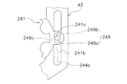
(C)前記実施形態及び前記他の実施形態(A)では、係合ピン49が、凸部41bに係合する場合の例を示した。これに代えて、図5に示すように、係合ピン249を、凸部241bに対して回転可能に係合させてもよい。
(C) In the said embodiment and said other embodiment (A), the example in case the
この場合、係合ピン249の一端部249aは、凸部241bに設けられた孔部241cに対して回転可能に装着される。係合ピン249の一端部249aは、例えば円形状に形成される。また、係合ピン249の他端部249bは、溝部244aの1対の壁部に各別に対向する1対の直線部249cを、有している。この場合、係合ピン249がベルト241とともに移動すると、係合ピン249の一端部249aが孔部241cにおいて回転しながら、係合ピン249の他端部249bが溝部244aの壁部に沿って移動する。このように構成しても、オシレーティング機構31を機能させることができる。
In this case, one
(D)前記実施形態では、ベルト41において環状部41aの外周部に1対の凸部41bが設けられる場合の例を示したが、環状部41aの外周全体に複数の凸部41bを設けてもよい。
(D) In the above-described embodiment, an example in which a pair of
1 スピニングリール
11 リール本体
13 ハンドル
31 オシレーティング機構
33 ハウジング
35 回転伝達機構
35a 第1ギア
35b 第2ギア
37 第1プーリ
37b 第1歯部
39 第2プーリ
39b 第2歯部
41 ベルト
41a 環状部
41b 凸部
41c 凹部
43 スライダ
44a 溝部
49,149,249 係合ピン
DESCRIPTION OF
Claims (7)
ハンドルの巻取り操作に連動して回転する第1回転体と、
スプール軸が延びるスプール軸方向に沿って前記第1回転体と間隔を隔てて配置される第2回転体と、
前記第1回転体及び前記第2回転体に架け渡され前記第1回転体の回転を第2回転体に伝達するベルト部材と、
前記ベルト部材及び前記移動体に係合する係合体と、
前記係合体を介して前記ベルト部材と係合し、前記ベルト部材の作動に伴い前記スプール軸方向に往復移動する移動体と、
を備え、
前記ベルト部材は、環状部と、前記環状部の外周部に設けられる凸部とを、有し、
前記係合体は、前記凸部に係合する、
釣用リールの往復移動機構。 A reciprocating mechanism for a fishing reel,
A first rotating body that rotates in conjunction with the winding operation of the handle;
A second rotator disposed at a distance from the first rotator along a spool axis direction in which the spool shaft extends;
A belt member that spans the first rotating body and the second rotating body and transmits the rotation of the first rotating body to the second rotating body;
An engagement body engaged with the belt member and the movable body;
A movable body that engages with the belt member via the engagement body and reciprocates in the spool axial direction in accordance with the operation of the belt member ;
Equipped with a,
The belt member has an annular portion and a convex portion provided on an outer peripheral portion of the annular portion,
The engaging body engages with the convex portion;
A reciprocating mechanism for fishing reels.
請求項1に記載の釣用リールの往復移動機構。 The engaging body engages between the pair of convex portions.
The reciprocating mechanism of the fishing reel according to claim 1 .
前記係合体は、前記溝部に沿って移動可能に前記溝部に係合する、
請求項1又は2に記載の釣用リールの往復移動機構。 The movable body has a groove portion extending in a direction inconsistent with the spool shaft,
The engaging body engages with the groove part so as to be movable along the groove part.
The reciprocating mechanism of the fishing reel according to claim 1 or 2 .
前記第1回転体は、前記凹部に噛み合う第1歯部を、有する、
請求項1から3のいずれか1項に記載の釣用リールの往復移動機構。 The belt member has an annular portion and a recess provided in an inner peripheral portion of the annular portion,
The first rotating body has a first tooth portion that meshes with the concave portion,
The reciprocating mechanism of the fishing reel according to any one of claims 1 to 3 .
請求項4に記載の釣用リールの往復移動機構。 The second rotating body has a second tooth portion that meshes with the concave portion,
The reciprocating mechanism of the fishing reel according to claim 4 .
さらに備える請求項1から5のいずれか1項に記載の釣用リールの往復移動機構。 A housing capable of accommodating the first rotating body, the second rotating body, and the belt member ;
The fishing reel reciprocating mechanism according to any one of claims 1 to 5 , further comprising:
をさらに備える請求項1から6のいずれか1項に記載の釣用リールの往復移動機構。
A rotation transmission mechanism for transmitting rotation from the drive shaft that rotates in conjunction with the winding operation of the handle to the first rotating body;
Further comprising reciprocating mechanism of the fishing reel according to any one of claims 1 6.
Priority Applications (7)
| Application Number | Priority Date | Filing Date | Title |
|---|---|---|---|
| JP2015110581A JP6558957B2 (en) | 2015-05-29 | 2015-05-29 | Fishing reel reciprocating mechanism |
| KR1020160038319A KR102583873B1 (en) | 2015-05-29 | 2016-03-30 | Reciprocation mechanism for fishing reel |
| TW105113562A TWI681715B (en) | 2015-05-29 | 2016-04-29 | Reciprocating movement mechanism of fishing tackle reel |
| US15/150,818 US9770017B2 (en) | 2015-05-29 | 2016-05-10 | Reciprocating mechanism for a fishing reel |
| MYPI2016701858A MY177759A (en) | 2015-05-29 | 2016-05-24 | Reciprocating mechanism for a fishing reel |
| EP16171268.2A EP3097781B1 (en) | 2015-05-29 | 2016-05-25 | Reciprocating mechanism for a spinning reel |
| CN201610359330.9A CN106172289B (en) | 2015-05-29 | 2016-05-27 | Reciprocating mechanism for fishing reel |
Applications Claiming Priority (1)
| Application Number | Priority Date | Filing Date | Title |
|---|---|---|---|
| JP2015110581A JP6558957B2 (en) | 2015-05-29 | 2015-05-29 | Fishing reel reciprocating mechanism |
Publications (3)
| Publication Number | Publication Date |
|---|---|
| JP2016220621A JP2016220621A (en) | 2016-12-28 |
| JP2016220621A5 JP2016220621A5 (en) | 2018-06-21 |
| JP6558957B2 true JP6558957B2 (en) | 2019-08-14 |
Family
ID=56080338
Family Applications (1)
| Application Number | Title | Priority Date | Filing Date |
|---|---|---|---|
| JP2015110581A Active JP6558957B2 (en) | 2015-05-29 | 2015-05-29 | Fishing reel reciprocating mechanism |
Country Status (7)
| Country | Link |
|---|---|
| US (1) | US9770017B2 (en) |
| EP (1) | EP3097781B1 (en) |
| JP (1) | JP6558957B2 (en) |
| KR (1) | KR102583873B1 (en) |
| CN (1) | CN106172289B (en) |
| MY (1) | MY177759A (en) |
| TW (1) | TWI681715B (en) |
Families Citing this family (4)
| Publication number | Priority date | Publication date | Assignee | Title |
|---|---|---|---|---|
| JP6908447B2 (en) | 2017-06-27 | 2021-07-28 | 株式会社シマノ | Reciprocating mechanism of fishing reel |
| JP2022097274A (en) * | 2020-12-18 | 2022-06-30 | 株式会社シマノ | Spinning reel |
| JP2022101312A (en) * | 2020-12-24 | 2022-07-06 | シマノコンポネンツ マレーシア エスディーエヌ.ビーエッチディー. | Spinning reel reciprocation mechanism and spinning reel with the reciprocation mechanism |
| KR20220167742A (en) * | 2021-06-14 | 2022-12-21 | 시마노 컴포넌츠 (말레이지아) 에스디엔. 비에이치디. | Spinning reel |
Family Cites Families (19)
| Publication number | Priority date | Publication date | Assignee | Title |
|---|---|---|---|---|
| SE390865B (en) * | 1975-07-03 | 1977-01-31 | Abu Ab | LENS SPREADING DEVICE AT A REEL ROLLER |
| JPS52101788U (en) * | 1976-01-28 | 1977-08-02 | ||
| JPS5918863A (en) * | 1982-07-19 | 1984-01-31 | タマパツク株式会社 | Gate opening and closing method and apparatus |
| JPS5918863U (en) * | 1982-07-27 | 1984-02-04 | 河野 正春 | Reel with chain drive operation |
| JPH0547583Y2 (en) * | 1988-09-05 | 1993-12-15 | ||
| JPH0521663U (en) | 1991-09-09 | 1993-03-23 | 株式会社シマノ | Oscillating mechanism of spinning reel |
| JPH0686467U (en) * | 1993-05-27 | 1994-12-20 | ダイワ精工株式会社 | Spinning reel for fishing |
| GB2280581B (en) | 1993-08-04 | 1996-12-11 | Shimano Kk | Spinning reel |
| JP3199351B2 (en) * | 1995-07-04 | 2001-08-20 | ダイワ精工株式会社 | Spinning reel |
| CN1198300A (en) * | 1997-05-05 | 1998-11-11 | 查理斯·C·沃斯公司 | Fishing reel tension bail mechanism |
| US6179236B1 (en) * | 2000-02-18 | 2001-01-30 | Jang Deok-Soo | Device for driving a spinning reel for fishing |
| TW504366B (en) * | 2000-12-04 | 2002-10-01 | Shimano Kk | Displaying device for fishing reel |
| US20030122010A1 (en) * | 2001-12-31 | 2003-07-03 | Wiest Timothy A. | Uniform oscillation system |
| JP2004081077A (en) * | 2002-08-26 | 2004-03-18 | Shimano Inc | Reciprocation mechanism for spinning reel |
| JP4299180B2 (en) * | 2003-08-27 | 2009-07-22 | 株式会社シマノ | Spinning reel reciprocating device |
| JP2007189982A (en) * | 2006-01-20 | 2007-08-02 | Shimano Inc | Gear part-fitting structure for fishing reel |
| JP2009055848A (en) * | 2007-08-31 | 2009-03-19 | Daiwa Seiko Inc | Spinning reel for fishing |
| GB201200912D0 (en) | 2012-01-19 | 2012-02-29 | Airbus Operations Ltd | Fastener receptacle strip |
| CN104322469A (en) * | 2014-10-17 | 2015-02-04 | 宁波海宝渔具有限公司 | Variable-speed spinning wheel type line reel for fishing |
-
2015
- 2015-05-29 JP JP2015110581A patent/JP6558957B2/en active Active
-
2016
- 2016-03-30 KR KR1020160038319A patent/KR102583873B1/en active IP Right Grant
- 2016-04-29 TW TW105113562A patent/TWI681715B/en active
- 2016-05-10 US US15/150,818 patent/US9770017B2/en active Active
- 2016-05-24 MY MYPI2016701858A patent/MY177759A/en unknown
- 2016-05-25 EP EP16171268.2A patent/EP3097781B1/en active Active
- 2016-05-27 CN CN201610359330.9A patent/CN106172289B/en active Active
Also Published As
| Publication number | Publication date |
|---|---|
| KR102583873B1 (en) | 2023-10-04 |
| MY177759A (en) | 2020-09-23 |
| KR20200067226A (en) | 2020-06-12 |
| CN106172289B (en) | 2021-02-02 |
| US20160345561A1 (en) | 2016-12-01 |
| JP2016220621A (en) | 2016-12-28 |
| EP3097781B1 (en) | 2018-09-26 |
| US9770017B2 (en) | 2017-09-26 |
| TW201701756A (en) | 2017-01-16 |
| CN106172289A (en) | 2016-12-07 |
| TWI681715B (en) | 2020-01-11 |
| EP3097781A1 (en) | 2016-11-30 |
Similar Documents
| Publication | Publication Date | Title |
|---|---|---|
| JP6558957B2 (en) | Fishing reel reciprocating mechanism | |
| JP2016220621A5 (en) | ||
| EP2853159B1 (en) | Fishing spinning reel | |
| TWI604789B (en) | Reciprocation mechanism for fishing reel | |
| JP6818083B2 (en) | Spinning reel for fishing | |
| EP2918168A2 (en) | Bail support mechanism for a spinning reel | |
| JP6875266B2 (en) | Spinning reel for fishing | |
| US10327431B2 (en) | Reciprocating mechanism for a fishing reel | |
| JP2007075074A (en) | Spinning reel for fishing | |
| JP6376756B2 (en) | Fishing reel reciprocating mechanism | |
| JP2015128403A5 (en) | ||
| JP7385525B2 (en) | spinning reel | |
| JP2006197892A (en) | Spinning reel for fishing | |
| JP5330971B2 (en) | Fishing spinning reel | |
| JP2009291212A (en) | Spinning reel for fishing | |
| JP2007014207A (en) | Spinning reel for fishing | |
| JP2007135408A (en) | Spinning reel for fishing | |
| JP2006197855A (en) | Spinning reel for fishing | |
| JP2016192938A (en) | Reciprocating mechanism of fishing reel | |
| JP2007000012A (en) | Spinning reel for fishing | |
| JP2007006786A (en) | Spinning reel for fishing |
Legal Events
| Date | Code | Title | Description |
|---|---|---|---|
| A521 | Request for written amendment filed |
Free format text: JAPANESE INTERMEDIATE CODE: A523 Effective date: 20180508 |
|
| A621 | Written request for application examination |
Free format text: JAPANESE INTERMEDIATE CODE: A621 Effective date: 20180508 |
|
| A977 | Report on retrieval |
Free format text: JAPANESE INTERMEDIATE CODE: A971007 Effective date: 20190130 |
|
| A131 | Notification of reasons for refusal |
Free format text: JAPANESE INTERMEDIATE CODE: A131 Effective date: 20190305 |
|
| A521 | Request for written amendment filed |
Free format text: JAPANESE INTERMEDIATE CODE: A523 Effective date: 20190426 |
|
| TRDD | Decision of grant or rejection written | ||
| A01 | Written decision to grant a patent or to grant a registration (utility model) |
Free format text: JAPANESE INTERMEDIATE CODE: A01 Effective date: 20190625 |
|
| A61 | First payment of annual fees (during grant procedure) |
Free format text: JAPANESE INTERMEDIATE CODE: A61 Effective date: 20190716 |
|
| R150 | Certificate of patent or registration of utility model |
Ref document number: 6558957 Country of ref document: JP Free format text: JAPANESE INTERMEDIATE CODE: R150 |
|
| R250 | Receipt of annual fees |
Free format text: JAPANESE INTERMEDIATE CODE: R250 |
|
| R250 | Receipt of annual fees |
Free format text: JAPANESE INTERMEDIATE CODE: R250 |