CN106172289B - Reciprocating mechanism for fishing reel - Google Patents
Reciprocating mechanism for fishing reel Download PDFInfo
- Publication number
- CN106172289B CN106172289B CN201610359330.9A CN201610359330A CN106172289B CN 106172289 B CN106172289 B CN 106172289B CN 201610359330 A CN201610359330 A CN 201610359330A CN 106172289 B CN106172289 B CN 106172289B
- Authority
- CN
- China
- Prior art keywords
- rotating body
- pulley
- rotation
- spool
- reciprocating mechanism
- Prior art date
- Legal status (The legal status is an assumption and is not a legal conclusion. Google has not performed a legal analysis and makes no representation as to the accuracy of the status listed.)
- Active
Links
Images


Classifications
-
- A—HUMAN NECESSITIES
- A01—AGRICULTURE; FORESTRY; ANIMAL HUSBANDRY; HUNTING; TRAPPING; FISHING
- A01K—ANIMAL HUSBANDRY; CARE OF BIRDS, FISHES, INSECTS; FISHING; REARING OR BREEDING ANIMALS, NOT OTHERWISE PROVIDED FOR; NEW BREEDS OF ANIMALS
- A01K89/00—Reels
- A01K89/01—Reels with pick-up, i.e. with the guiding member rotating and the spool not rotating during normal retrieval of the line
- A01K89/0114—Reciprocating mechanisms
- A01K89/01142—Reciprocating mechanisms for reciprocating the guiding member
- A01K89/01143—Reversely threaded screws
-
- A—HUMAN NECESSITIES
- A01—AGRICULTURE; FORESTRY; ANIMAL HUSBANDRY; HUNTING; TRAPPING; FISHING
- A01K—ANIMAL HUSBANDRY; CARE OF BIRDS, FISHES, INSECTS; FISHING; REARING OR BREEDING ANIMALS, NOT OTHERWISE PROVIDED FOR; NEW BREEDS OF ANIMALS
- A01K89/00—Reels
- A01K89/01—Reels with pick-up, i.e. with the guiding member rotating and the spool not rotating during normal retrieval of the line
- A01K89/0114—Reciprocating mechanisms
- A01K89/01141—Reciprocating mechanisms including eccentric cams reciprocating the spool
-
- A—HUMAN NECESSITIES
- A01—AGRICULTURE; FORESTRY; ANIMAL HUSBANDRY; HUNTING; TRAPPING; FISHING
- A01K—ANIMAL HUSBANDRY; CARE OF BIRDS, FISHES, INSECTS; FISHING; REARING OR BREEDING ANIMALS, NOT OTHERWISE PROVIDED FOR; NEW BREEDS OF ANIMALS
- A01K89/00—Reels
- A01K89/015—Reels with a rotary drum, i.e. with a rotating spool
Abstract
The invention provides a reciprocating mechanism which can be miniaturized in a direction orthogonal to a spool axis. The swing mechanism (31) is provided with: a first pulley (37), a second pulley (39), a conveyor belt (41), and a sliding body (43). The first pulley (37) rotates in conjunction with the winding operation of the handle (13). The second pulley (39) is disposed at an interval from the first pulley (37) in the axial direction. The belt (41) is bridged between the first pulley (37) and the second pulley (39), and transmits the rotation of the first pulley (37) to the second pulley (39). The sliding body (43) engages with the conveyor belt (41) and reciprocates in the axial direction in accordance with the movement of the conveyor belt (41).
Description
Technical Field
The present invention relates to a reciprocating mechanism for a fishing reel.
Background
In general, a spinning reel includes a reciprocating mechanism that reciprocates a spool in a front-rear direction with respect to a reel unit in order to uniformly wind a fishing line around the spool (see patent document 1). A conventional reciprocating mechanism mainly includes a rotary driving body (first rotating body), a rotary driven body (second rotating body), an intermediate transmission body (rotation transmission body), and a sliding body (moving body). The rotation driving body rotates by the rotation of the handle shaft. The rotary driven body and the rotary driven body are disposed at a distance. The intermediate transmission body transmits the rotation of the rotary drive body to the rotary driven body. The sliding body is arranged on the reel shaft and is clamped with the rotary driven body.
Patent document 1: japanese patent laid-open No. 2009-55848.
In a conventional reciprocating mechanism, a slider is engaged with a rotation driven member. Specifically, the rotation follower has a snap projection. The sliding body has a cam groove for engaging the engaging projection. The cam groove is formed in a vertically long zigzag shape and extends in a direction substantially orthogonal to the spool axial direction.
In this configuration, when the rotary driven body is rotated by the rotation of the rotary drive body, the engagement projection of the rotary driven body moves along the cam groove of the slider in a direction in which the cam groove of the slider extends, that is, in a direction substantially orthogonal to the spool axis direction (a direction orthogonal to the spool axis). Then, the slider moves in the front-rear direction together with the spool shaft.
In this case, the amount of movement of the slider in the front-rear direction, that is, the stroke amount of the spool is set by adjusting the length of the cam groove of the slider in the direction orthogonal to the spool axis. For example, the longer the length of the cam groove of the slider is set, the larger the stroke amount of the spool becomes.
However, if the length of the cam groove of the slider is set long, the slider needs to be set long in the direction perpendicular to the spool axis. Further, when the engaging projection of the rotary driven body is moved within a range in which the cam groove of the slide body extends, the diameter of the rotary driven body needs to be increased. That is, there are problems as follows: in the conventional traverse mechanism, in order to increase the stroke amount of the spool, the traverse mechanism is increased in size in the direction orthogonal to the spool axis.
Disclosure of Invention
The present invention has been made in view of the above problems, and an object of the present invention is to provide a reciprocating mechanism that can be miniaturized in a direction orthogonal to a spool axis.
(1) A reciprocating mechanism for a fishing reel according to one aspect of the present invention includes: a first rotating body, a second rotating body, a rotation transmission body, and a moving body. The first rotating body rotates in conjunction with the winding operation of the handle. The second rotating body is disposed at a distance from the first rotating body along the spool axis direction in which the spool axis extends. The rotation transmission body is bridged on the first rotating body and the second rotating body and transmits the rotation of the first rotating body to the second rotating body. The movable body engages with the rotation transmission body and reciprocates in the spool axis direction in accordance with the operation of the rotation transmission body.
In this reciprocating mechanism, when the winding operation of the handle is performed, the first rotating body rotates in conjunction with the winding operation. Then, the second rotating body rotates via the rotation transmitting body. Then, the movable body engaged with the rotation transmitting body reciprocates in the spool axis direction.
Thus, in the reciprocating mechanism, the distance between the first rotating body and the second rotating body is adjusted in the spool axis direction, thereby setting the amount of movement of the movable body in the spool axis direction, that is, the stroke amount of the spool. For example, the larger the above-described interval is set, the larger the stroke amount of the spool becomes. In this way, the stroke amount of the spool can be increased without changing the size of the reciprocating mechanism in the direction orthogonal to the spool axis. That is, compared to the conventional art, the reciprocating mechanism can be downsized in the direction orthogonal to the spool axis.
(2) The reciprocating mechanism of a fishing reel according to another aspect of the present invention preferably further includes an engaging body. The engaging member engages the rotation transmitting member and the movable member.
In this case, the rotation transmission body and the movable body are engaged with each other by the engaging body. Thus, the movable body can be reliably reciprocated in the spool axis direction by the engaging body when the rotation transmitting body is operated.
(3) In the fishing reel reciprocating mechanism relating to another aspect of the present invention, the rotation transmitting body preferably includes: the annular portion, set up in the convex part of the peripheral part of the annular portion. The engaging body is engaged with the convex portion.
In this case, the engaging body can be easily provided on the outer peripheral portion of the annular portion of the rotation transmission body via the convex portion of the rotating body.
(4) In the fishing reel reciprocating mechanism relating to another aspect of the present invention, the rotation transmitting body preferably includes: the annular portion, set up in a pair of convex parts of the peripheral part of the annular portion. The engaging body is engaged between the pair of protrusions.
In this case, the engaging body can be more easily provided on the outer peripheral portion of the annular portion of the rotation transmission body via the convex portion of the rotation transmission body.
(5) In the fishing reel reciprocating mechanism relating to another aspect of the present invention, the movable body preferably has a groove portion extending in a direction that does not coincide with the spool shaft. The engaging body is movably engaged with the groove along the groove.
In this case, even if the groove portion extends in a direction not coinciding with the spool shaft, the stroke amount of the spool can be set by adjusting the interval between the first rotating body and the second rotating body in the axial direction without changing the length of the groove portion. That is, compared to the conventional art, the reciprocating mechanism can be made compact in the direction orthogonal to the spool axis.
(6) In the fishing reel reciprocating mechanism relating to another aspect of the present invention, the rotation transmitting body preferably includes: the annular portion, set up the recess of the inner peripheral portion of annular portion. The first rotating body has a first tooth portion engaged with the recess.
In this case, the rotation of the first rotating body can be reliably transmitted to the annular portion of the rotation transmitting body by the meshing of the first tooth portion and the concave portion.
(7) In the fishing reel reciprocating mechanism according to another aspect of the present invention, the second rotating body preferably has a second tooth portion that engages with the recess.
In this case, the rotation of the first rotating body can be reliably transmitted from the annular portion of the rotation transmitting body to the second rotating body by the engagement of the second tooth portion and the concave portion.
(8) The reciprocating mechanism for a fishing reel according to another aspect of the present invention preferably further includes a housing. The housing can house the first rotating body, the second rotating body, and the rotation transmission body.
In this case, since the belt is guided by the housing, even if the moving body breaks down when moving in the spool axis direction, slack occurs in the belt, or the like, the belt can be prevented from being disengaged (disengaged) from the first rotating body and the second rotating body.
(9) The reciprocating mechanism for a fishing reel according to another aspect of the present invention preferably further includes a rotation transmission mechanism. The rotation transmission mechanism transmits rotation from a drive shaft to the first rotating body, and the drive shaft rotates in conjunction with the winding operation of the handle.
In this case, even if the drive shaft and the first rotating body are disposed at separate positions, the rotation from the drive shaft can be reliably transmitted to the first rotating body via the rotation transmitting mechanism.
With the reciprocating mechanism of the present invention, the reciprocating mechanism can be miniaturized in the direction orthogonal to the spool axis.
Drawings
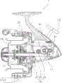
Fig. 1 is a side sectional view of a spinning reel according to an embodiment of the present invention.
Fig. 2 is a side view of the swing mechanism.
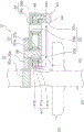
Fig. 3 is a sectional view of the swing mechanism (the position of a sectional line III-III of fig. 2).
Fig. 4 is a diagram showing an engagement state of the engagement pin in another embodiment of the present invention.
Fig. 5 is a diagram showing an engagement state of the engagement pin in another embodiment of the present invention.
Detailed Description
Schematic structure of spinning reel
The spinning reel 1 according to the embodiment of the present invention is a reel that can reel out fishing line forward. As shown in fig. 1, the spinning reel 1 includes: the reel unit 11, the handle 13, the rotation driving mechanism 15, the spool 19 having the spool shaft 17, the rolling element 21, and the oscillating mechanism 31 (an example of a reciprocating mechanism).
Hereinafter, there are cases as follows: the direction in which the fishing line is sequentially discharged forward is referred to as "forward (left side in fig. 1)" and the direction opposite to the direction in which the fishing line is sequentially discharged forward is referred to as "backward (right side in fig. 1)". In addition, there are cases as follows: the side of the reel body 11 that is fitted to the fishing rod is expressed as "upper side (upper side in fig. 1)", and the direction opposite to the side of the reel body 11 that is fitted to the fishing rod is expressed as "lower side (lower side in fig. 1)".
In addition, the direction in which the spool shaft 17 extends (spool shaft direction), the direction in which the pinion 27 extends (pinion shaft direction), and the direction in which the guide shaft 51 extends (guide shaft direction) are substantially the same direction. Therefore, these directions are hereinafter expressed as "axial directions".
The reel unit 11 rotatably supports the handle 13 and the rotor 21. The reel unit 11 supports the spool 19 so as to be capable of reciprocating in the axial direction. The handle 13 is rotatably supported by the reel unit 11 around an axis extending in a direction orthogonal to the axial direction (e.g., an axis orthogonal to the paper surface of fig. 1).
The rotation driving mechanism 15 transmits the rotation of the handle 13 to the rolling body 21 and the swing mechanism 31. The rotary drive mechanism 15 has a drive shaft 23, a drive gear 25, and a pinion gear 27.
The drive shaft 23 rotates in conjunction with the winding operation of the handle 13. Specifically, the drive shaft 23 is integrally rotatably coupled to the handle 13.
The drive gear 25 has a face gear. The drive gear 25 rotates integrally with the drive shaft 23. The pinion gear 27 is a cylindrical gear that meshes with the drive gear 25. The pinion gear 27 is rotatably supported by the reel unit 11. The spool shaft 17 penetrates an inner peripheral portion of the pinion gear 27. The rolling element 21 is connected to the pinion gear 27 so as to be rotatable integrally with the pinion gear 27.
The spool 19 is disposed in front of the reel unit 11 and reciprocates in the axial direction together with the spool shaft 17. At this time, the rotor 21 rotates on the outer peripheral side of the spool 19, and the spool 19 reciprocates in the axial direction, whereby the fishing line is uniformly wound around the spool 19. Specifically, the spool 19 is coupled to one end of the spool shaft 17. A swing mechanism 31 is coupled to the other end of the spool shaft 17. The spool shaft 17 reciprocates in the axial direction on the inner peripheral portion of the pinion gear 27 by the swing mechanism 31.
Structure of swing mechanism
The swing mechanism 31 is provided to wind the fishing line uniformly around the spool 19. The swing mechanism 31 reciprocates the spool 19 in the axial direction via the spool shaft 17 by rotation of the handle 13.
As shown in fig. 1 to 3, the swing mechanism 31 includes a housing 33, a rotation transmission mechanism 35, a first pulley 37 (an example of a first rotating body), a second pulley 39 (an example of a second rotating body), a conveyor belt 41 (an example of a rotation transmission body), a sliding body 43 (an example of a moving body), an engagement pin 49 (an example of an engagement body), and a guide shaft 51. In addition, the housing 33 is omitted in fig. 1 for ease of view, and the housing 33 is indicated by a two-dot chain line in fig. 2.
The housing 33 can house the first pulley 37, the second pulley 39, and the conveyor belt 41. Specifically, as shown in fig. 2 and 3, the housing 33 includes a pair of first hole portions 33a, a pair of second hole portions 33b, and a guide hole portion 33 c. The pair of first holes 33a rotatably support the first pulley 37. The pair of second holes 33b is provided at an interval from the pair of first holes 33a along the axial direction. The pair of second holes 33b rotatably support the second pulley 39.
The guide hole 33c guides the engagement pin 49. As shown in fig. 2, when the housing 33 is viewed along the rotation axis of the first pulley 37 and/or the rotation axis of the second pulley 39 (e.g., an axis perpendicular to the paper surface of fig. 2), the guide hole portion 33c is formed in a non-circular shape, for example, a substantially elliptical shape, so as to extend along the conveyor belt 41. The engagement pin 49 is inserted into the guide hole 33 c.
The rotation transmission mechanism 35 transmits the rotation from the drive shaft 23 to the first pulley 37. Specifically, as shown in fig. 2 and 3, the rotation transmission mechanism 35 includes a first gear 35a and a second gear 35 b. The first gear 35a is integrally rotatably fitted to the drive shaft 23. The second gear 35b meshes with the first gear 35 a. A shaft portion 36 is integrally rotatably attached to the second gear 35 b.
The first pulley 37 rotates in conjunction with the winding operation of the handle 13. Specifically, as shown in fig. 2 and 3, the first pulley 37 includes a first cylindrical portion 37a and a first tooth portion 37 b. The first cylindrical portion 37a is rotatably fitted to the housing 33. For example, as shown in fig. 3, both end portions of the first cylindrical portion 37a are respectively provided rotatably with respect to the pair of first hole portions 33 a. The shaft portion 36 is inserted through the inner peripheral portion of the first cylindrical portion 37 a. The first cylindrical portion 37a is rotatable integrally with the shaft portion 36. The first teeth 37b are provided on the outer peripheral portion of the first cylindrical portion 37 a.
The second pulley 39 rotates in conjunction with the rotation of the first pulley 37. Specifically, as shown in fig. 2 and 3, the second pulley 39 is disposed at an interval from the first pulley 37 in the axial direction. The second pulley 39 has a second cylindrical portion 39a and a second tooth portion 39 b. The second cylindrical portion 39a is rotatably fitted to the housing 33. For example, both end portions of the second cylindrical portion 39a are rotatably fitted to the pair of second hole portions 33b of the housing 33, respectively. The second tooth portion 39b is provided on the outer peripheral portion of the second cylindrical portion 39 a. The second cylindrical portion 39a may be a solid cylindrical portion.
As shown in fig. 2, the belt 41 is bridged between the first pulley 37 and the second pulley 39, and transmits the rotation of the first pulley 37 to the second pulley 39. Specifically, the conveyor belt 41 has an annular portion 41a, a pair of convex portions 41b, and a plurality of concave portions 41 c. The annular portion 41a is a portion bridged over the first pulley 37 and the second pulley 39. The pair of projections 41b are provided on the outer peripheral portion of the annular portion 41 a. An engagement pin 49 is engaged between the pair of convex portions 41 b. The plurality of recesses 41c are provided on the inner peripheral portion of the annular portion 41 a. The first tooth 37b of the first pulley 37 and the second tooth 39b of the second pulley 39 are engaged with the plurality of recesses 41 c.
The slider 43 engages with the conveyor belt 41 and reciprocates in the axial direction in accordance with the movement of the conveyor belt 41. Specifically, as shown in fig. 2 and 3, the slider 43 has a slider main body 44, a first fitting portion 45, and a second fitting portion 47. The slider body 44 is provided with a groove 44 a. The groove portion 44a extends in a direction not coinciding with the spool shaft 17, for example, in a direction orthogonal to the spool shaft 17. An engagement pin 49 is disposed in the groove portion 44a, and the engagement pin 49 is fixed between the pair of convex portions 41b of the conveyor belt 41. In this manner, the slider body 44 is engaged with the conveyor belt 41 via the engagement pin 49.
As shown in fig. 2, the spool shaft 17 is fitted on the first fitting portion 45. Specifically, an end portion (rear end portion) of the spool shaft 17 is fixed to a non-circular hole portion 45a, which is formed in the first fitting portion 45, by a fixing means such as a screw member so as not to rotate. A guide shaft 51 is fitted on the second fitting portion 47. In detail, the guide shaft 51 is inserted through the second fitting portion 47 so that the slider 43 can move in the axial direction along the guide shaft 51.
The engagement pin 49 is engaged with the conveyor belt 41 and the slider 43. Specifically, as shown in fig. 2 and 3, one end of the engagement pin 49 is fixed between the pair of convex portions 41b of the conveyor belt 41 by a fixing means such as an adhesive. The other end of the engagement pin 49 is inserted into the guide hole 33c of the housing 33 and engaged with the groove 44a of the slider 43. Thus, when the engagement pin 49 moves together with the conveyor belt 41 during the operation of the conveyor belt 41, the engagement pin 49 moves along the groove portion 44 a.
As shown in fig. 1 and 2, the guide shaft 51 guides the slider 43 in the axial direction. The guide shaft 51 is provided to the reel unit 11 along the axial direction.
Operation of the oscillating mechanism
Here, the operation of the swing mechanism 31 will be described.
When the handle 13 is rotated, the drive gear 25 rotates together with the drive shaft 23. Then, the pinion gear 27 meshed with the drive gear rotates, and the rolling element 21 rotates on the outer peripheral side of the drum 19 by the rotation.
On the other hand, when the handle 13 is rotated, the rotation transmission mechanism 35 (the first gear 35a and the second gear 35 b) operates together with the drive shaft 23. Then, the rotation of the drive shaft 23 is transmitted to the first pulley 37 via the rotation transmission mechanism 35. Then, the first pulley 37 and the second pulley 39 rotate via the belt 41.
Here, when the first pulley 37 and the second pulley 39 rotate, the belt 41 rotates around the first pulley 37 and the second pulley 39 in a state of being bridged on the first pulley 37 and the second pulley 39. At this time, one end of the engaging pin 49 moves around the first pulley 37 and the second pulley 39 together with the belt 41. At this time, the other end portion of the engagement pin 49 reciprocates along the groove portion 44a of the slider 43 while engaging with the groove portion 44a (see the arrow in fig. 2 and 3). Then, the slider 43 reciprocates in the axial direction.
When the slider 43 reciprocates in the axial direction in this manner, the spool shaft 17 to which the slider 43 is fixed also reciprocates in the axial direction. That is, the drum 19 reciprocates relative to the rotor 21. At this time, the rotor 21 rotates on the outer peripheral side of the spool 19, and the fishing line is wound around the spool 19 by the rotation of the rotor 21.
Feature(s)
(1) The swing mechanism 31 includes a first pulley 37, a second pulley 39, a conveyor belt 41, and a slider 43. The first pulley 37 rotates in conjunction with the winding operation of the handle 13. The second pulley 39 is disposed at an interval from the first pulley 37 in the axial direction. The belt 41 is bridged between the first pulley 37 and the second pulley 39, and transmits the rotation of the first pulley 37 to the second pulley 39. The slider 43 engages with the conveyor belt 41 and reciprocates in the axial direction in accordance with the movement of the conveyor belt 41.
In the swing mechanism 31, when the winding operation of the handle 13 is performed, the first pulley 37 rotates in conjunction with the winding operation. Then, the second pulley 39 is rotated via the conveyor belt 41. Then, the slider 43 engaged with the conveyor belt 41 reciprocates in the axial direction.
Thus, in the swing mechanism 31, the distance between the first pulley 37 and the second pulley 39 is adjusted in the axial direction, thereby setting the amount of movement of the slider 43 in the axial direction, that is, the stroke amount of the drum 19. For example, the larger the above-described interval is set, the larger the stroke amount of the spool 19 becomes. In this way, the stroke amount of the spool 19 can be increased without changing the size of the swing mechanism 31 in the direction orthogonal to the spool shaft 17. That is, the swing mechanism 31 can be made smaller in the direction orthogonal to the spool shaft 17 as compared with the conventional art.
(2) The swing mechanism 31 further includes an engagement pin 49. The engagement pin 49 preferably engages the conveyor belt 41 and the slider 43.
In this case, the conveyor belt 41 and the slider 43 are engaged by the engagement pin 49. Thus, when the conveyor belt 41 is operated, the slide body 43 can be reliably reciprocated in the axial direction by the engaging pin 49.
(3) In the swing mechanism 31, the conveyor belt 41 preferably has an annular portion 41a and a convex portion 41b provided on the outer peripheral portion of the annular portion 41 a. The engagement pin 49 engages with the convex portion 41 b.
In this case, the engaging pin 49 can be easily provided on the outer peripheral portion of the annular portion 41a of the conveyor belt 41 via the convex portion 41b of the conveyor belt 41.
(4) In the swing mechanism 31, the conveyor belt 41 preferably includes an annular portion 41a and a pair of convex portions 41b provided on the outer peripheral portion of the annular portion 41 a. The engagement pin 49 is engaged between the pair of convex portions 41 b.
In this case, the engaging pin 49 can be easily provided on the outer peripheral portion of the annular portion 41a of the conveyor belt 41 via the convex portion 41b of the conveyor belt 41.
(5) In this swing mechanism 31, the slider 43 preferably has a groove portion 44a extending in a direction not coinciding with the spool shaft 17. The engagement pin 49 is movably engaged with the groove portion 44a along the groove portion 44 a.
In this case, even if the groove portion 44a extends in a direction not coinciding with the spool shaft 17, the stroke amount of the spool can be set by adjusting the interval between the first pulley 37 and the second pulley 39 in the axial direction without changing the length of the groove portion 44 a. That is, the swing mechanism 31 can be reliably downsized in the direction orthogonal to the spool shaft 17 as compared with the conventional art.
(6) In the swing mechanism 31, the conveyor belt 41 preferably has an annular portion 41a and a recessed portion 41c provided on the inner peripheral portion of the annular portion 41 a. The first pulley 37 has a first tooth 37b engaged with the recess 41 c.
In this case, the rotation of the first pulley 37 can be reliably transmitted to the annular portion 41a of the conveyor belt 41 by the engagement of the first tooth portion 37b and the concave portion 41 c.
(7) In this swing mechanism 31, the second pulley 39 preferably has a second tooth portion 39b that engages with the recess 41 c.
In this case, the rotation of the first pulley 37 can be reliably transmitted from the annular portion 41a of the conveyor belt 41 to the second pulley 39 by the engagement of the second tooth portion 39b and the concave portion 41 c.
(8) The swing mechanism 31 preferably further includes a housing 33. The housing 33 can house the first pulley 37, the second pulley 39, and the conveyor belt 41.
In this case, since the belt 41 is guided by the housing 33, even if the slider 43 (spool shaft 17) fails to move in the axial direction or slack occurs in the belt 41, the belt 41 can be prevented from being disengaged (disengaged) from the first pulley 37 and the second pulley 39.
(9) The fishing-reel swing mechanism 31 according to another aspect of the present invention preferably further includes a rotation transmission mechanism 35 (e.g., a first gear 35a and a second gear 35 b). The rotation transmission mechanism 35 transmits rotation from the drive shaft 23 to the first pulley 37, and the drive shaft 23 rotates in conjunction with the winding operation of the handle 13.
In this case, even if the drive shaft 23 and the first pulley 37 are disposed at separate positions, the rotation from the drive shaft 23 can be reliably transmitted to the first pulley 37 via the rotation transmission mechanism 35.
Other embodiments
(A) In the above embodiment, an example in which the engaging pin 49 is fixed between the pair of convex portions 41b is shown. Instead of this embodiment, as shown in fig. 4, one convex portion 141b may be provided on the conveyor belt 141, and the engagement pin 149 may be engaged with the convex portion 141 b. In this case, for example, the one end 149a of the engaging pin 149 is formed in a non-circular shape, for example, a rectangular shape. The convex portion 141b is provided with a hole portion 141c into which one end portion 149a of the engagement pin 149 can be engaged. One end 149a of the engagement pin 149 is fixed to the hole 141c by a fixing means such as an adhesive.
(B) In the above embodiment, an example in which the engaging pin 49 is fixed between the pair of convex portions 41b is shown. Instead of this embodiment, the engagement pin 49 may be formed integrally with the conveyor belt 41.
(C) In the above-described embodiment and the other embodiment (a), an example in which the engaging pin 49 is engaged with the convex portion 41b is shown. Instead of this embodiment, as shown in fig. 5, the engagement pin 249 may be rotatably engaged with the convex portion 241 b.
In this case, one end 249a of the engagement pin 249 is rotatably fitted to the hole 241c provided in the convex portion 241 b. One end 249a of the engagement pin 249 is formed in a circular shape, for example. The other end 249b of the engagement pin 249 has a pair of linear portions 249c facing the pair of wall portions of the groove portion 244 a. In this case, when the engagement pin 249 moves together with the conveyor belt 241, one end 249a of the engagement pin 249 rotates in the hole 241c, and the other end 249b of the engagement pin 249 moves along the wall of the groove 44 a. Even with this configuration, the swing mechanism 31 can function.
(D) In the above embodiment, the case where the pair of convex portions 41b are provided on the outer peripheral portion of the annular portion 41a of the conveyor belt 41 has been described, but a plurality of convex portions 41b may be provided on the entire outer peripheral portion of the annular portion 41 a.
Description of the reference numerals
1a spinning reel; 11 a reel body; 13 a handle; 31 a swing mechanism; 33a housing; 35a rotation transmission mechanism; 35a first gear; 35b a second gear; 37a first pulley; 37b a first tooth; 39a second pulley; 39b second tooth portion; 41a conveyor belt; 41a ring-shaped part; 41b convex parts; 41c a recess; 43 a sliding body; 44a groove portion; 49. 149, 249 engage the pin.
Claims (7)
1. A reciprocating mechanism for a fishing reel, comprising: a first rotating body, a second rotating body, a rotation transmitting body, and a moving body,
the first rotating body rotates in conjunction with the winding operation of the handle,
the second rotating body is disposed at a distance from the first rotating body along the spool axis direction in which the spool axis extends,
the rotation transmission body is mounted on the first rotating body and the second rotating body and transmits the rotation of the first rotating body to the second rotating body,
the movable body is engaged with the rotation transmission body and reciprocates in the spool axial direction in accordance with the operation of the rotation transmission body,
further comprises a engaging member for engaging the rotation transmitting member and the movable member,
the rotation transmission body has: an annular portion, a convex portion provided on an outer peripheral portion of the annular portion,
the engaging body is engaged with the convex portion.
2. A reciprocating mechanism for a fishing reel according to claim 1,
the engaging body is engaged between the pair of protrusions.
3. A reciprocating mechanism for a fishing reel according to claim 1 or 2,
the movable body has a groove portion extending in a direction not coinciding with the spool axis,
the engaging body is movably engaged with the groove along the groove.
4. A reciprocating mechanism for a fishing reel according to claim 1 or 2,
the rotation transmission body has: an annular portion, a recess provided in an inner peripheral portion of the annular portion,
the first rotating body has a first tooth portion engaged with the recess.
5. A reciprocating mechanism for a fishing reel according to claim 4,
the second rotating body has a second tooth portion engaged with the recess.
6. A reciprocating mechanism for a fishing reel according to claim 1 or 2,
the device further includes a housing capable of housing the first rotating body, the second rotating body, and the rotation transmission body.
7. A reciprocating mechanism for a fishing reel according to claim 1 or 2,
the winding device further includes a rotation transmission mechanism for transmitting rotation from a drive shaft to the first rotating body, wherein the drive shaft rotates in conjunction with the winding operation of the handle.
Applications Claiming Priority (2)
| Application Number | Priority Date | Filing Date | Title |
|---|---|---|---|
| JP2015-110581 | 2015-05-29 | ||
| JP2015110581A JP6558957B2 (en) | 2015-05-29 | 2015-05-29 | Fishing reel reciprocating mechanism |
Publications (2)
| Publication Number | Publication Date |
|---|---|
| CN106172289A CN106172289A (en) | 2016-12-07 |
| CN106172289B true CN106172289B (en) | 2021-02-02 |
Family
ID=56080338
Family Applications (1)
| Application Number | Title | Priority Date | Filing Date |
|---|---|---|---|
| CN201610359330.9A Active CN106172289B (en) | 2015-05-29 | 2016-05-27 | Reciprocating mechanism for fishing reel |
Country Status (7)
| Country | Link |
|---|---|
| US (1) | US9770017B2 (en) |
| EP (1) | EP3097781B1 (en) |
| JP (1) | JP6558957B2 (en) |
| KR (1) | KR102583873B1 (en) |
| CN (1) | CN106172289B (en) |
| MY (1) | MY177759A (en) |
| TW (1) | TWI681715B (en) |
Families Citing this family (4)
| Publication number | Priority date | Publication date | Assignee | Title |
|---|---|---|---|---|
| JP6908447B2 (en) * | 2017-06-27 | 2021-07-28 | 株式会社シマノ | Reciprocating mechanism of fishing reel |
| JP2022097274A (en) * | 2020-12-18 | 2022-06-30 | 株式会社シマノ | Spinning reel |
| JP2022101312A (en) * | 2020-12-24 | 2022-07-06 | シマノコンポネンツ マレーシア エスディーエヌ.ビーエッチディー. | Spinning reel reciprocation mechanism and spinning reel with the reciprocation mechanism |
| KR20220167742A (en) * | 2021-06-14 | 2022-12-21 | 시마노 컴포넌츠 (말레이지아) 에스디엔. 비에이치디. | Spinning reel |
Citations (7)
| Publication number | Priority date | Publication date | Assignee | Title |
|---|---|---|---|---|
| US5364041A (en) * | 1991-09-09 | 1994-11-15 | Shimano Inc. | Oscillating mechanism for a spinning reel |
| US5601244A (en) * | 1993-08-04 | 1997-02-11 | Shimano Inc. | Spinning reel with movable line guide along reel axis |
| CN1198300A (en) * | 1997-05-05 | 1998-11-11 | 查理斯·C·沃斯公司 | Fishing reel tension bail mechanism |
| CN1357225A (en) * | 2000-12-04 | 2002-07-10 | 株式会社岛野 | Display of fishing line winder |
| CN101002550A (en) * | 2006-01-20 | 2007-07-25 | 株式会社岛野 | Gear mounting structure for fishing reel |
| JP2009055848A (en) * | 2007-08-31 | 2009-03-19 | Daiwa Seiko Inc | Spinning reel for fishing |
| CN104322469A (en) * | 2014-10-17 | 2015-02-04 | 宁波海宝渔具有限公司 | Variable-speed spinning wheel type line reel for fishing |
Family Cites Families (12)
| Publication number | Priority date | Publication date | Assignee | Title |
|---|---|---|---|---|
| SE390865B (en) * | 1975-07-03 | 1977-01-31 | Abu Ab | LENS SPREADING DEVICE AT A REEL ROLLER |
| JPS52101788U (en) * | 1976-01-28 | 1977-08-02 | ||
| JPS5918863A (en) * | 1982-07-19 | 1984-01-31 | タマパツク株式会社 | Gate opening and closing method and apparatus |
| JPS5918863U (en) * | 1982-07-27 | 1984-02-04 | 河野 正春 | Reel with chain drive operation |
| JPH0547583Y2 (en) * | 1988-09-05 | 1993-12-15 | ||
| JPH0686467U (en) * | 1993-05-27 | 1994-12-20 | ダイワ精工株式会社 | Spinning reel for fishing |
| JP3199351B2 (en) * | 1995-07-04 | 2001-08-20 | ダイワ精工株式会社 | Spinning reel |
| US6179236B1 (en) * | 2000-02-18 | 2001-01-30 | Jang Deok-Soo | Device for driving a spinning reel for fishing |
| US20030122010A1 (en) * | 2001-12-31 | 2003-07-03 | Wiest Timothy A. | Uniform oscillation system |
| JP2004081077A (en) * | 2002-08-26 | 2004-03-18 | Shimano Inc | Reciprocation mechanism for spinning reel |
| JP4299180B2 (en) * | 2003-08-27 | 2009-07-22 | 株式会社シマノ | Spinning reel reciprocating device |
| GB201200912D0 (en) | 2012-01-19 | 2012-02-29 | Airbus Operations Ltd | Fastener receptacle strip |
-
2015
- 2015-05-29 JP JP2015110581A patent/JP6558957B2/en active Active
-
2016
- 2016-03-30 KR KR1020160038319A patent/KR102583873B1/en active IP Right Grant
- 2016-04-29 TW TW105113562A patent/TWI681715B/en active
- 2016-05-10 US US15/150,818 patent/US9770017B2/en active Active
- 2016-05-24 MY MYPI2016701858A patent/MY177759A/en unknown
- 2016-05-25 EP EP16171268.2A patent/EP3097781B1/en active Active
- 2016-05-27 CN CN201610359330.9A patent/CN106172289B/en active Active
Patent Citations (7)
| Publication number | Priority date | Publication date | Assignee | Title |
|---|---|---|---|---|
| US5364041A (en) * | 1991-09-09 | 1994-11-15 | Shimano Inc. | Oscillating mechanism for a spinning reel |
| US5601244A (en) * | 1993-08-04 | 1997-02-11 | Shimano Inc. | Spinning reel with movable line guide along reel axis |
| CN1198300A (en) * | 1997-05-05 | 1998-11-11 | 查理斯·C·沃斯公司 | Fishing reel tension bail mechanism |
| CN1357225A (en) * | 2000-12-04 | 2002-07-10 | 株式会社岛野 | Display of fishing line winder |
| CN101002550A (en) * | 2006-01-20 | 2007-07-25 | 株式会社岛野 | Gear mounting structure for fishing reel |
| JP2009055848A (en) * | 2007-08-31 | 2009-03-19 | Daiwa Seiko Inc | Spinning reel for fishing |
| CN104322469A (en) * | 2014-10-17 | 2015-02-04 | 宁波海宝渔具有限公司 | Variable-speed spinning wheel type line reel for fishing |
Also Published As
| Publication number | Publication date |
|---|---|
| EP3097781B1 (en) | 2018-09-26 |
| TWI681715B (en) | 2020-01-11 |
| KR20200067226A (en) | 2020-06-12 |
| CN106172289A (en) | 2016-12-07 |
| US9770017B2 (en) | 2017-09-26 |
| EP3097781A1 (en) | 2016-11-30 |
| TW201701756A (en) | 2017-01-16 |
| US20160345561A1 (en) | 2016-12-01 |
| JP2016220621A (en) | 2016-12-28 |
| KR102583873B1 (en) | 2023-10-04 |
| JP6558957B2 (en) | 2019-08-14 |
| MY177759A (en) | 2020-09-23 |
Similar Documents
| Publication | Publication Date | Title |
|---|---|---|
| CN106172289B (en) | Reciprocating mechanism for fishing reel | |
| ATE521232T1 (en) | OSCILLATING MECHANISM FOR FISHING REEL | |
| US10779522B2 (en) | Rotation transmission mechanism and spinning reel for fishing having the same | |
| EP2853159A2 (en) | Fishing spinning reel | |
| KR20150088167A (en) | Reciprocation mechanism for fishing reel | |
| JP2016220621A5 (en) | ||
| JP6818083B2 (en) | Spinning reel for fishing | |
| KR102312398B1 (en) | Oscillation mechanism for fishing reel | |
| JP6875266B2 (en) | Spinning reel for fishing | |
| US10327431B2 (en) | Reciprocating mechanism for a fishing reel | |
| CN110679563B (en) | Spinning wheel type winder | |
| US20190090466A1 (en) | Dual-bearing reel | |
| EP4190150A1 (en) | Fishing spinning reel | |
| JP2006197892A (en) | Spinning reel for fishing | |
| JP2018057360A (en) | Bait reel | |
| JP2006197855A (en) | Spinning reel for fishing | |
| JPH06245673A (en) | Spinning reel for fishing |
Legal Events
| Date | Code | Title | Description |
|---|---|---|---|
| C06 | Publication | ||
| PB01 | Publication | ||
| SE01 | Entry into force of request for substantive examination | ||
| SE01 | Entry into force of request for substantive examination | ||
| GR01 | Patent grant | ||
| GR01 | Patent grant |