EP3697620B1 - Tintentankdeckel und ventilgestänge - Google Patents
Tintentankdeckel und ventilgestänge Download PDFInfo
- Publication number
- EP3697620B1 EP3697620B1 EP17928844.4A EP17928844A EP3697620B1 EP 3697620 B1 EP3697620 B1 EP 3697620B1 EP 17928844 A EP17928844 A EP 17928844A EP 3697620 B1 EP3697620 B1 EP 3697620B1
- Authority
- EP
- European Patent Office
- Prior art keywords
- valve
- ink tank
- cap assembly
- effector
- spring
- Prior art date
- Legal status (The legal status is an assumption and is not a legal conclusion. Google has not performed a legal analysis and makes no representation as to the accuracy of the status listed.)
- Active
Links
Images


Classifications
-
- B—PERFORMING OPERATIONS; TRANSPORTING
- B41—PRINTING; LINING MACHINES; TYPEWRITERS; STAMPS
- B41L—APPARATUS OR DEVICES FOR MANIFOLDING, DUPLICATING OR PRINTING FOR OFFICE OR OTHER COMMERCIAL PURPOSES; ADDRESSING MACHINES OR LIKE SERIES-PRINTING MACHINES
- B41L27/00—Inking arrangements or devices
- B41L27/04—Ducts, containers, or supply devices or ink-level control devices
-
- B—PERFORMING OPERATIONS; TRANSPORTING
- B41—PRINTING; LINING MACHINES; TYPEWRITERS; STAMPS
- B41J—TYPEWRITERS; SELECTIVE PRINTING MECHANISMS, i.e. MECHANISMS PRINTING OTHERWISE THAN FROM A FORME; CORRECTION OF TYPOGRAPHICAL ERRORS
- B41J1/00—Typewriters or selective printing mechanisms characterised by the mounting, arrangement or disposition of the types or dies
-
- B—PERFORMING OPERATIONS; TRANSPORTING
- B41—PRINTING; LINING MACHINES; TYPEWRITERS; STAMPS
- B41J—TYPEWRITERS; SELECTIVE PRINTING MECHANISMS, i.e. MECHANISMS PRINTING OTHERWISE THAN FROM A FORME; CORRECTION OF TYPOGRAPHICAL ERRORS
- B41J2/00—Typewriters or selective printing mechanisms characterised by the printing or marking process for which they are designed
- B41J2/005—Typewriters or selective printing mechanisms characterised by the printing or marking process for which they are designed characterised by bringing liquid or particles selectively into contact with a printing material
- B41J2/01—Ink jet
- B41J2/17—Ink jet characterised by ink handling
- B41J2/175—Ink supply systems ; Circuit parts therefor
- B41J2/17503—Ink cartridges
- B41J2/17513—Inner structure
-
- B—PERFORMING OPERATIONS; TRANSPORTING
- B41—PRINTING; LINING MACHINES; TYPEWRITERS; STAMPS
- B41J—TYPEWRITERS; SELECTIVE PRINTING MECHANISMS, i.e. MECHANISMS PRINTING OTHERWISE THAN FROM A FORME; CORRECTION OF TYPOGRAPHICAL ERRORS
- B41J2/00—Typewriters or selective printing mechanisms characterised by the printing or marking process for which they are designed
- B41J2/005—Typewriters or selective printing mechanisms characterised by the printing or marking process for which they are designed characterised by bringing liquid or particles selectively into contact with a printing material
- B41J2/01—Ink jet
- B41J2/17—Ink jet characterised by ink handling
- B41J2/175—Ink supply systems ; Circuit parts therefor
- B41J2/17503—Ink cartridges
- B41J2/1752—Mounting within the printer
- B41J2/17523—Ink connection
-
- B—PERFORMING OPERATIONS; TRANSPORTING
- B41—PRINTING; LINING MACHINES; TYPEWRITERS; STAMPS
- B41J—TYPEWRITERS; SELECTIVE PRINTING MECHANISMS, i.e. MECHANISMS PRINTING OTHERWISE THAN FROM A FORME; CORRECTION OF TYPOGRAPHICAL ERRORS
- B41J2/00—Typewriters or selective printing mechanisms characterised by the printing or marking process for which they are designed
- B41J2/005—Typewriters or selective printing mechanisms characterised by the printing or marking process for which they are designed characterised by bringing liquid or particles selectively into contact with a printing material
- B41J2/01—Ink jet
- B41J2/17—Ink jet characterised by ink handling
- B41J2/175—Ink supply systems ; Circuit parts therefor
- B41J2/17503—Ink cartridges
- B41J2/17536—Protection of cartridges or parts thereof, e.g. tape
- B41J2/1754—Protection of cartridges or parts thereof, e.g. tape with means attached to the cartridge, e.g. protective cap
-
- B—PERFORMING OPERATIONS; TRANSPORTING
- B41—PRINTING; LINING MACHINES; TYPEWRITERS; STAMPS
- B41J—TYPEWRITERS; SELECTIVE PRINTING MECHANISMS, i.e. MECHANISMS PRINTING OTHERWISE THAN FROM A FORME; CORRECTION OF TYPOGRAPHICAL ERRORS
- B41J2/00—Typewriters or selective printing mechanisms characterised by the printing or marking process for which they are designed
- B41J2/005—Typewriters or selective printing mechanisms characterised by the printing or marking process for which they are designed characterised by bringing liquid or particles selectively into contact with a printing material
- B41J2/01—Ink jet
- B41J2/17—Ink jet characterised by ink handling
- B41J2/175—Ink supply systems ; Circuit parts therefor
- B41J2/17503—Ink cartridges
- B41J2/17553—Outer structure
-
- B—PERFORMING OPERATIONS; TRANSPORTING
- B41—PRINTING; LINING MACHINES; TYPEWRITERS; STAMPS
- B41J—TYPEWRITERS; SELECTIVE PRINTING MECHANISMS, i.e. MECHANISMS PRINTING OTHERWISE THAN FROM A FORME; CORRECTION OF TYPOGRAPHICAL ERRORS
- B41J2/00—Typewriters or selective printing mechanisms characterised by the printing or marking process for which they are designed
- B41J2/005—Typewriters or selective printing mechanisms characterised by the printing or marking process for which they are designed characterised by bringing liquid or particles selectively into contact with a printing material
- B41J2/01—Ink jet
- B41J2/17—Ink jet characterised by ink handling
- B41J2/175—Ink supply systems ; Circuit parts therefor
- B41J2/17596—Ink pumps, ink valves
Definitions
- Printers are commonplace, whether in a home environment or an office environment. Such printers can include laser printer, inkjet printers or other types. Generally, printers require at least one consumable, such as paper or ink. Ink may be provided for the printers in cartridges that may be replaceable or refillable.
- US6367918 discloses a latching device for ink jet cartridges.
- US 2005/151799 discloses an ink cartridge holder for use in squeezing ink out of an ink cartridge.
- Bubbler-style ink tanks for inkjet printers require a seal at the ink fill port during printing to create and maintain the negative back pressure required to prevent excessive ink flow due to gravity when the ink supply is located above the print head assembly. Breaking the seal to fill the ink tank may result in ink drool or flooding at the print head assembly.
- various examples provide for linking the cap and valve actuations of external and internal seals of an ink tank.
- the linkage facilitates sealing of a valve in the ink tank before an external seal is broken and negative backpressure in the ink tank is lost.
- the cap of the ink tank is automatically forced to a first, partially opened position by a pre-loaded hinge, while the cap remains sealed and the valve is actuated (i.e., closed).
- the cap includes an effector that actuates the valve through the linkage.
- the present disclosure describes example apparatus, methods and systems to facilitate the linked activation of cap and valve seals of an ink tank.
- an apparatus is disclosed in claim 1
- a related method is disclosed in claim 6
- a related system is disclosed in claim 11.
- An example apparatus is described below with reference to Figure 1 .
- Example ink tank 100 includes an ink tank body 101, which may be a multi-chambered ink tank as described in greater detail below.
- the example ink tank 100 also includes a cap assembly 102 attached to the ink tank 100 with a hinge, such as hinge 103 illustrated in Figure 1 , which may be preloaded.
- the cap assembly 102 is shown in a latched (closed) state.
- Cap assembly 102 is attached to the example ink tank 100 by the hinge 103.
- Hinge 103 may be any type of hinge that constrains the rotation of the cap assembly 102 to a single axis of rotation.
- hinge 103 may be an axle engaged with cylindrical bearings extending from the cap assembly 102.
- hinge 103 may be preloaded with an elastic band 104 disposed around the hinge 103 to apply an opening force to the cap assembly 102, such that when the cap assembly 102 is unlatched, the opening force applied by the elastic band 104 rotates the cap assembly 102 to a fully opened position and maintains the cap assembly 102 in the fully opened position until the force is overcome by force applied by a user to close the cap assembly 102.
- Example ink tank 100 also includes a latch 105 to hold the cap assembly 102 in a closed position against the opening force applied by the elastic band 104 as illustrated in Figure 1 . Accordingly, the cap assembly 102 is constrained to two stable states: a closed state (closed position) as illustrated in Figure 1 when the latch 105 is engaged, and a fully opened state (fully opened position) when the latch is released, as described and illustrated below.
- a closed state closed position
- a fully opened state fully opened position
- Figure 2 is a perspective illustration of the ink cap assembly 102 in the closed position
- Figure 3 is a perspective illustration of the example ink tank 100 with the cap assembly 102 in the fully opened position. It will be appreciated from these views that the elastic band 104 wraps around the ends of the axle of hinge 103 (as illustrated in Figure 3 ) and under the arms of the hinge 103 (as illustrated in Figure 3 ) to force to the cap assembly 102 to the fully open position as illustrated in Figure 3 .
- Figure 4 is a sectional view of an example cap assembly 102 illustrating internal details of cap assembly 102 in the closed position
- Figure 5 is a sectional view illustrating the cap assembly 102 of Figure 4 in a transient, partially open state after the cap assembly 102 has been unlatched by the operation of latch 105.
- the cap assembly includes a cap housing 106, a bung 107 retained within the cap housing 106, and a spring 108 disposed between the cap housing 106 and the bung 107.
- cap housing 106 may be fabricated from an acetal homopolymer thermoplastic such as Delrin, ® and the bung 107 may be fabricated from a natural or synthetic elastic polymer such as natural rubber or silicone rubber.
- the ink tank body 101 partial
- the elastic band 104 and the latch 105
- the spring 108 is compressed between the cap housing 106 and the bung 107 and applies a sealing force between the bung 107 and the ink tank body 101.
- the bung 107 may include an O-ring 109 to improve the seal between the bung 107 and the ink tank body 101.
- the bung 107 is retained within cap housing 106 by a number of complementary features comprising tabs or protuberances from the bung 107 and openings, cavities or channels in the cap housing 106.
- Figure 5 is a sectional view illustrating the cap assembly 102 of Figure 4 in a transient, partially open state after the cap assembly 102 has been unlatched by the operation of latch 105.
- This transient state is achieved by the combined forces of spring 108 and hinge 104.
- spring 108 applies a force to push the cap housing 102 away from the bung 107 while maintaining a sealing force between the bung 107 and the ink tank body 101. It will be appreciated that this force decreases as spring 108 decompresses and that the relative motion of the cap housing 106 and the bung 107 is limited by the complementary features of the cap assembly 106 and the bung 107 described above.
- this transient position serves to actuate a valve in the ink tank (using other features of the cap housing 102) to effect a secondary seal in the ink tank body 101 before the seal between the bung 107 and the ink tank body 101 is broken.
- further motion of the cap assembly 102 is controlled by the force applied to the cap assembly 102 by the elastic band 104. As described previously, this force rotates the cap assembly to a fully open position.
- Figure 6 is a sectional view illustrating the cap assembly 102 of Figures 4 and 5 in the fully open state. In this state, further rotation is limited by interference between a sidewall 116 of the ink tank body 101 and a flange 117 of the hinge 103 (not visible in Figure 6 ).
- Figure 7 illustrates the side view of the example ink tank 100 previously illustrated in Figure 1 .
- the cap assembly 102 is in the closed (latched) state.
- an effector 201 an extension of cap assembly 102 extends downward from the cap assembly 102 to depress a slider 202, which is retained in a channel in the body of the ink tank 100.
- the slider may be retained by any means known in the art, such as by channels or tabs, for example.
- the slider 202 is engaged with a cam on lever arm 203 that is spring loaded by a spring 204, and holds the lever arm 203 in a downward position against the force of the spring 204.
- Lever arm 203 is fixed to a rotatable spline 205 that extends into the interior of the ink tank body 101.
- spline 205 may be held in place by a snap-ring or c-clip, and sealed by an O-ring or the like as it passes through the wall of the ink tank body 101.
- FIG 8 is a perspective illustration of the linkage described above, in isolation, showing additional details not visible in Figure 7 .
- the sealed pinion 205 is fixed to a second lever arm 206, which in turn is connected to a valve body 207 by a pin 208 that is fixed with respect to lever arm 206 and free to rotate with respect to valve body 207.
- Valve body 207 includes a valve seal 209 that is configured to provide a seal when seated in a valve seat 210 in the ink tank (see Figure 9 ).
- lever arm 203 is held in a downward rotated position by the slider 202, that lever arm 206 is held in an upward rotated position by its fixed connection to lever arm 203 via spline 205, and that the valve assembly comprising valve seal 209 and valve seat 210 is held open.
- Figure 9 is a partial sectional (cutaway) view of the example ink tank 100, showing internal details of the ink tank and the valve linkage described above in the closed cap configuration.
- lever arm 206 is in its upward rotated position, which translates through valve body 207 to an unseated valve seal 209.
- an upper chamber 301 of ink tank body 101 and a lower chamber 401 of ink tank body 101, also referred to as a feeder tank.
- the valve assembly is positioned between the upper chamber 301 and the lower chamber 401 and permits fluid commination between the upper chamber 301 and the lower chamber 401.
- FIG. 10 there is illustrated a side view of the example ink tank 100 with the cap in the transient, partially open state described above.
- the cap assembly 102 is partially open, such that the cap housing 106 is partially rotated and the bung (107) to ink tank (101) seal is maintained, but the holding force applied by effector 201 is removed from slider 202, which allows the force of spring 204 to rotate lever arm 203 upward (clockwise in Figure 10 ).
- the angle of rotation of the cap assembly 102 relative to the closed position may be in the range of approximately 10 to 14 degrees.
- Figure 11 is a partial sectional (cutaway) view of the example ink tank 100, showing internal details of the ink tank and the valve linkage described above in the transient, partially open cap state.
- lever arm 206 is rotated downward, which translates through valve body 207 to seat valve seal 209 into value seat 210, thereby providing a seal between upper chamber 301 and lower chamber 401and preventing fluid communication between the upper chamber 301 and the lower chamber 401.
- Figure 12 illustrates the example ink tank 100 with the cap assembly rotated to its fully opened position under the force applied by the elastic band 104 described above. It will be appreciated that the internal seal between valve seal 209 and valve seat 210 will be maintained as the cap assembly 102 rotates from the transient position to the fully opened position because the effector 201 remains disengaged from the slider 202, allowing the spring 204 to hold the lever arm 203 in its upward rotated position. As described above, this position of lever arm 203 corresponds to the seating of valve seal 209 in valve seat 210.
- the sequence of events that occurs when the cap is opened is reversible when the cap assembly 102 is closed by a user.
- the internal valve is closed and the upper chamber 301 of ink tank body 101 is not sealed by the bung 107.
- the bung (107) seals the upper chamber 301 of ink tank (101) and the effector 201 engages the slider 202.
- the effector 201 depresses slider 202, which rotates lever arm 203 downward and lever arm 206 upward to unseat valve seal 209 from valve seat 210, reestablishing fluid communication between upper chamber 301 of ink tank body 101 and lower chamber 401 of ink tank body 101.
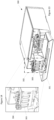
- Figure 13 illustrates an example printer system 300 with an access door 301 in an open position to allow access to an ink tank bay 302 containing at least one ink tank, such as example ink tank 303, for filling or refilling.
- Figure 14 is a magnified view of the ink tank bay 302 illustrating one of the example ink tanks 303 and a cap assembly 304 in a fully opened position.
- the example ink tank 303 and the cap assembly 304 may be similar to the example ink tank 100 and cap assembly 102 described above with reference to Figures 1-12 .
- the cap assembly 304 is attached to the ink tank with a preloaded hinge to rotate the cap assembly 304 from a closed position to an open position when the cap assembly 304 is unlatched.
- the cap assembly 304 of Figure 14 may include a bung to seal the ink tank during a partial rotation of the cap assembly 304 when the cap assembly 304 is unlatched.
- a spring-loaded linkage may be provided and may be connected to a valve in the ink tank.
- An effector may extend from the cap assembly 304 to engage and actuate the spring-loaded linkage when the cap assembly 304 is latched and to disengage from the spring-loaded linkage after the cap assembly 304 is unlatched.
- the spring-loaded linkage opens the valve when engaged with the effector, and closes the valve when disengaged from the effector.
- the bung maintains a tank seal until the internal valve is closed.
- a flowchart illustrates an example method 500 for linking cap and valve actuation in an ink tank.
- the example method includes sealing an ink tank with a cap assembly comprising a bung and an effector, such as cap assembly 102 in Figure 4 illustrating bung 107, and cap assembly 102 in Figure 7 illustrating effector 201 (block 501).
- Example method 500 further includes rotating the cap assembly from a closed position to a first position with a preloaded hinge to close a valve in the ink tank (block 502).
- Figure 10 illustrates cap assembly 102 rotated by hinge 104 to a first, partially rotated position to disengage effector 201 from the external linkage comprising slider 202, external lever arm 203, hinge 204, and sealed spline 205.
- Figure 11 illustrates the internal linkage comprising lever arm 206, valve body 207, and valve seal 209 seated in valve seat 210 to seal (close) the valve.
- example method 500 includes rotating the cap assembly to a second position with the preloaded hinge, where the ink tank is unsealed and the valve in the ink tank remains closed (block 503).
- Figures 12 illustrates cap 102 rotated to a second, fully opened position where the effector 102 is disengaged from the linkage described above, and the linkage is in the same position as in Figure 10 , corresponding to a closed valve
- linking the actuation of the external cap and internal valve of an ink tank during ink filling operations insures that a valve internal to the ink tank is sealed before an external seal is broken and negative backpressure in the cartridge's ink tank is lost.
Landscapes
- Ink Jet (AREA)
- Closures For Containers (AREA)
- Engineering & Computer Science (AREA)
- Mechanical Engineering (AREA)
Claims (11)
- Vorrichtung, die umfasst:einen Tintenbehälter;eine Kappenanordnung (102, 304), die an dem Tintenbehälter mit einem vorbelasteten Scharnier (103) befestigt ist, das dazu konfiguriert ist, die Kappenanordnung (102, 304) von einer geschlossenen Position in eine offene Position zu drehen, wenn die Kappenanordnung (102, 304) entriegelt ist, wobei die Kappenanordnung (102, 304) einen Spund (107) umfasst, um den Tintenbehälter während einer teilweisen Drehung der Kappenanordnung (102, 304) abzudichten, wenn die Kappenanordnung (102, 304) entriegelt ist;eine federbelastete Bindung, die mit einem Ventil in dem Tintenbehälter verbunden ist, wobei das Ventil eine sekundäre Dichtung in dem Tintenbehälterkörper (101) bereitstellt;einen Effektor (201), der sich von der Kappenanordnung (102, 304) erstreckt, dazu konfiguriert, die federbelastete Bindung in Eingriff zu nehmen und zu betätigen, wenn die Kappenanordnung (102, 304) verriegelt ist und dazu konfiguriert, sich von der federbelasteten Bindung zu lösen, nachdem die Kappenanordnung (102, 304) entriegelt ist, wobei die federbelastete Bindung dazu konfiguriert ist, das Ventil zu öffnen, wenn es mit dem Effektor (201) in Eingriff steht, und das Ventil zu schließen, wenn es von dem Effektor (201) gelöst ist, undwobei der Spund (107) dazu konfiguriert ist, eine Behälterdichtung während der Drehung der Kappenanordnung (102, 304) von der geschlossenen Position in die offene Position zu halten, bis das Ventil geschlossen ist, um die sekundäre Dichtung zu bewirken.
- Vorrichtung nach Anspruch 1, wobei der Tintenbehälter eine obere Kammer (301) und eine untere Kammer (401) und das Ventil dazwischen umfasst, wobei das Ventil einen Ventilkörper (207), eine Ventildichtung (209) und einen Ventilsitz (210) umfasst.
- Vorrichtung nach Anspruch 2, wobei die Vorrichtung ferner umfasst:einen ersten Hebelarm (206) innerhalb des Tintenbehälters, der mit dem Ventil gekoppelt ist;einen zweiten Hebelarm (203) außerhalb des Tintenbehälters;eine abgedichtete Keilnut (205), die an dem ersten Hebelarm (206) und dem zweiten Hebelarm (203) befestigt ist;eine Feder (108, 204), die mit dem zweiten Hebelarm (203) gekoppelt ist; undeinen Schieber (202), der mit dem zweiten Hebelarm (203) gekoppelt ist, um den Effektor (201) in Eingriff zu nehmen.
- Vorrichtung nach Anspruch 3, wobei die Feder (108, 204) betriebsfähig ist, um das Ventil in eine geschlossene Position vorzuspannen, wenn der Effektor (201) von dem Schieber (202) gelöst ist, wobei eine Fluidverbindung zwischen der oberen Kammer (301) und der unteren Kammer (401) verhindert wird.
- Vorrichtung nach Anspruch 3, wobei der Schieber (202) betriebsfähig ist, um das Ventil zu öffnen, wenn der Effektor (201) mit dem Schieber (202) in Eingriff steht, wobei die Fluidverbindung zwischen der oberen Kammer (301) und der unteren Kammer (401) aktiviert ist.
- Verfahren, das umfasst:Abdichten eines Tintenbehälters mit einer Kappenanordnung (102, 304), die einen Spund (107) und einen Effektor (201) umfasst;Drehen der Kappenanordnung (102, 304) von einer geschlossenen Position in eine erste Position mit einem vorbelasteten Scharnier (103), wobei ein Ventil in dem Tintenbehälter geschlossen ist, um eine sekundäre Dichtung des Tintenbehälters während der Drehung der Kappenanordnung (102, 304) zu bewirken, und bevor die Dichtung zwischen dem Spund (107) und einem Körper des Tintenbehälters gebrochen ist und die Ventilbetätigung mit der Kappenanordnungsbetätigung derart gebunden ist, dass der Effektor (201) das Ventil betätigt; undDrehen der Kappenanordnung (102, 304) in eine zweite Position mit dem vorbelasteten Scharnier (103), wobei der Tintenbehälter nicht abgedichtet ist und das Ventil in dem Tintenbehälter geschlossen bleibt.
- Verfahren nach Anspruch 6, das ferner umfasst:Drehen der Kappenanordnung (102, 304) von der zweiten Position in die erste Position, wobei der Tintenbehälter wieder abgedichtet wird und das Ventil geschlossen bleibt;Drehen der Kappenanordnung (102, 304) von der ersten Position in die geschlossene Position, wobei das Ventil geöffnet ist und der Tintenbehälter abgedichtet bleibt
- Verfahren nach Anspruch 6, wobei, wenn sich die Kappenanordnung (102, 304) in der geschlossenen Position befindet, der Effektor (201) in eine Ventilbindung eingreift, die das Ventil öffnet.
- Verfahren nach Anspruch 8, wobei, wenn sich die Kappenanordnung (102, 304) zwischen der ersten Position und der zweiten Position befindet, der Effektor (201) die Ventilbindung löst.
- Verfahren nach Anspruch 9, wobei das Ventil durch die Ventilbindung in eine geschlossene Position vorgespannt ist.
- System, das umfasst:eine Tintenbehältervertiefung (302);mindestens eine Vorrichtung nach einem der Ansprüche 1 bis 5, wobei mindestens ein Tintenbehälter in der Tintenbehältervertiefung (302) installiert ist.
Applications Claiming Priority (1)
| Application Number | Priority Date | Filing Date | Title |
|---|---|---|---|
| PCT/US2017/057742 WO2019078898A1 (en) | 2017-10-20 | 2017-10-20 | VALVE TANK AND INK TANK CAP CONNECTION |
Publications (3)
| Publication Number | Publication Date |
|---|---|
| EP3697620A1 EP3697620A1 (de) | 2020-08-26 |
| EP3697620A4 EP3697620A4 (de) | 2021-05-05 |
| EP3697620B1 true EP3697620B1 (de) | 2023-07-26 |
Family
ID=66173365
Family Applications (1)
| Application Number | Title | Priority Date | Filing Date |
|---|---|---|---|
| EP17928844.4A Active EP3697620B1 (de) | 2017-10-20 | 2017-10-20 | Tintentankdeckel und ventilgestänge |
Country Status (4)
| Country | Link |
|---|---|
| US (1) | US11046102B2 (de) |
| EP (1) | EP3697620B1 (de) |
| CN (1) | CN111212741B (de) |
| WO (1) | WO2019078898A1 (de) |
Families Citing this family (4)
| Publication number | Priority date | Publication date | Assignee | Title |
|---|---|---|---|---|
| US11305548B2 (en) * | 2017-10-20 | 2022-04-19 | Hewlett-Packard Development Company, L.P. | Cap seal and valve sequencing |
| JP2022057838A (ja) * | 2020-09-30 | 2022-04-11 | ブラザー工業株式会社 | インクタンク及び画像記録装置 |
| JP2022057839A (ja) * | 2020-09-30 | 2022-04-11 | ブラザー工業株式会社 | インクタンク及び画像記録装置 |
| JP2022057832A (ja) | 2020-09-30 | 2022-04-11 | ブラザー工業株式会社 | インクタンク及び画像記録装置 |
Family Cites Families (17)
| Publication number | Priority date | Publication date | Assignee | Title |
|---|---|---|---|---|
| US6367918B1 (en) * | 1994-10-31 | 2002-04-09 | Hewlett-Packard Company | Unitary latching device for secure positioning of print cartridge during printing, priming and replenishment |
| US5825387A (en) | 1995-04-27 | 1998-10-20 | Hewlett-Packard Company | Ink supply for an ink-jet printer |
| JP3713632B2 (ja) * | 1994-12-28 | 2005-11-09 | 富士写真フイルム株式会社 | インクカートリッジ、及びインクジェットプリンタ |
| US7114801B2 (en) | 1995-04-27 | 2006-10-03 | Hewlett-Packard Development Company, L.P. | Method and apparatus for providing ink to an ink jet printing system |
| US6948798B2 (en) * | 2001-05-31 | 2005-09-27 | Hewlett-Packard Development Company, L.P. | Method and apparatus for horizontally loading and unloading an ink-jet print cartridge from a carriage |
| US6481829B1 (en) * | 2001-09-18 | 2002-11-19 | Lexmark International, Inc. | Manually actuated carrier latch mechanism |
| CA2453170C (en) | 2002-12-20 | 2012-02-21 | Mold-Masters Limited | Lateral gating injection molding apparatus |
| DE102004001750B3 (de) * | 2004-01-12 | 2005-05-25 | Technotrans Ag | Farbkartuschen-Behälter |
| JP4821430B2 (ja) | 2006-05-16 | 2011-11-24 | ブラザー工業株式会社 | インクジェットプリンタ装置およびインクカートリッジの装着方法 |
| JP4809178B2 (ja) | 2006-09-29 | 2011-11-09 | 富士フイルム株式会社 | 液体吐出装置および液体供給方法 |
| DE102007001084A1 (de) * | 2006-12-12 | 2008-06-19 | Pelikan Hardcopy Production Ag | Tintenpatrone für Tintenstrahldrucker |
| TWI321525B (en) | 2007-01-02 | 2010-03-11 | Qisda Corp | Inkjet printers |
| JP4770768B2 (ja) | 2007-03-23 | 2011-09-14 | ブラザー工業株式会社 | 液滴吐出装置及び液滴吐出装置用のサブタンク |
| CN201176026Y (zh) * | 2008-03-21 | 2009-01-07 | 珠海中润靖杰打印机耗材有限公司 | 喷墨墨盒 |
| JP5298780B2 (ja) | 2008-11-04 | 2013-09-25 | セイコーエプソン株式会社 | 液体供給装置、印刷装置及び液体供給装置の制御方法 |
| CN201889955U (zh) * | 2010-10-18 | 2011-07-06 | 泰金宝电通股份有限公司 | 自动开盖装置以及使用此自动开盖装置的印表机 |
| JP5513695B1 (ja) * | 2014-01-09 | 2014-06-04 | 理想科学工業株式会社 | インクカートリッジ及びインクカートリッジ着脱機構 |
-
2017
- 2017-10-20 EP EP17928844.4A patent/EP3697620B1/de active Active
- 2017-10-20 CN CN201780095941.XA patent/CN111212741B/zh not_active Expired - Fee Related
- 2017-10-20 WO PCT/US2017/057742 patent/WO2019078898A1/en not_active Ceased
- 2017-10-20 US US16/499,255 patent/US11046102B2/en not_active Expired - Fee Related
Also Published As
| Publication number | Publication date |
|---|---|
| CN111212741B (zh) | 2022-05-27 |
| CN111212741A (zh) | 2020-05-29 |
| US11046102B2 (en) | 2021-06-29 |
| US20200238742A1 (en) | 2020-07-30 |
| EP3697620A4 (de) | 2021-05-05 |
| WO2019078898A1 (en) | 2019-04-25 |
| EP3697620A1 (de) | 2020-08-26 |
Similar Documents
| Publication | Publication Date | Title |
|---|---|---|
| EP3697620B1 (de) | Tintentankdeckel und ventilgestänge | |
| US6120138A (en) | Refill assembly for printer ink cartridges | |
| EP3623159B1 (de) | Tintenstrahlaufzeichnungsvorrichtung | |
| CA2550799A1 (en) | Cartridge unit having negatively pressurized ink storage | |
| US11220111B2 (en) | Ink cartridge caps | |
| US5933173A (en) | Holder for refilling and preserving an ink jet printhead | |
| JP2002103642A (ja) | インクジェット記録装置用インクカートリッジ | |
| US11305548B2 (en) | Cap seal and valve sequencing | |
| JP2017515749A (ja) | トリガー式通気孔を有する燃料タンクアセンブリ | |
| US5821967A (en) | Holder for refilling an ink jet printhead | |
| US11541663B2 (en) | Liquid ejection apparatus and liquid refill container | |
| US7303267B2 (en) | Actuator for automatic ink refill system | |
| US10654284B2 (en) | Fluid storage device with multi-position seal assembly | |
| JPH08290577A (ja) | インクタンク | |
| CN212636919U (zh) | 墨水补充容器及墨水装置 | |
| WO2006093472A1 (en) | Ink reservoir | |
| JP6327015B2 (ja) | 液体カートリッジ及び液体カートリッジのキャップ取付方法 | |
| US12459267B2 (en) | Liquid supply device | |
| US10967643B2 (en) | Liquid ejecting apparatus | |
| US11584128B2 (en) | Printhead priming and venting | |
| WO2020106278A1 (en) | Fluid supply valve | |
| JP2008173870A (ja) | 流体供給装置およびそれを用いた流体噴射装置 | |
| HK1028971A1 (en) | Ink cartridge for ink jet printer | |
| HK1028971B (en) | Ink cartridge for ink jet printer |
Legal Events
| Date | Code | Title | Description |
|---|---|---|---|
| STAA | Information on the status of an ep patent application or granted ep patent |
Free format text: STATUS: THE INTERNATIONAL PUBLICATION HAS BEEN MADE |
|
| PUAI | Public reference made under article 153(3) epc to a published international application that has entered the european phase |
Free format text: ORIGINAL CODE: 0009012 |
|
| STAA | Information on the status of an ep patent application or granted ep patent |
Free format text: STATUS: REQUEST FOR EXAMINATION WAS MADE |
|
| 17P | Request for examination filed |
Effective date: 20200330 |
|
| AK | Designated contracting states |
Kind code of ref document: A1 Designated state(s): AL AT BE BG CH CY CZ DE DK EE ES FI FR GB GR HR HU IE IS IT LI LT LU LV MC MK MT NL NO PL PT RO RS SE SI SK SM TR |
|
| AX | Request for extension of the european patent |
Extension state: BA ME |
|
| DAV | Request for validation of the european patent (deleted) | ||
| DAX | Request for extension of the european patent (deleted) | ||
| A4 | Supplementary search report drawn up and despatched |
Effective date: 20210408 |
|
| RIC1 | Information provided on ipc code assigned before grant |
Ipc: B41L 27/04 20060101AFI20210331BHEP Ipc: B65D 43/16 20060101ALI20210331BHEP |
|
| REG | Reference to a national code |
Ref country code: DE Ref legal event code: R079 Ref document number: 602017071990 Country of ref document: DE Free format text: PREVIOUS MAIN CLASS: B41L0027040000 Ipc: B41J0002175000 Ref country code: DE Ref legal event code: R079 Free format text: PREVIOUS MAIN CLASS: B41L0027040000 Ipc: B41J0002175000 |
|
| GRAP | Despatch of communication of intention to grant a patent |
Free format text: ORIGINAL CODE: EPIDOSNIGR1 |
|
| STAA | Information on the status of an ep patent application or granted ep patent |
Free format text: STATUS: GRANT OF PATENT IS INTENDED |
|
| RIC1 | Information provided on ipc code assigned before grant |
Ipc: B41J 1/00 20060101ALI20230209BHEP Ipc: B41L 27/04 20060101ALI20230209BHEP Ipc: B41J 2/175 20060101AFI20230209BHEP |
|
| INTG | Intention to grant announced |
Effective date: 20230313 |
|
| GRAS | Grant fee paid |
Free format text: ORIGINAL CODE: EPIDOSNIGR3 |
|
| GRAA | (expected) grant |
Free format text: ORIGINAL CODE: 0009210 |
|
| STAA | Information on the status of an ep patent application or granted ep patent |
Free format text: STATUS: THE PATENT HAS BEEN GRANTED |
|
| AK | Designated contracting states |
Kind code of ref document: B1 Designated state(s): AL AT BE BG CH CY CZ DE DK EE ES FI FR GB GR HR HU IE IS IT LI LT LU LV MC MK MT NL NO PL PT RO RS SE SI SK SM TR |
|
| REG | Reference to a national code |
Ref country code: CH Ref legal event code: EP |
|
| REG | Reference to a national code |
Ref country code: IE Ref legal event code: FG4D |
|
| REG | Reference to a national code |
Ref country code: DE Ref legal event code: R096 Ref document number: 602017071990 Country of ref document: DE |
|
| REG | Reference to a national code |
Ref country code: LT Ref legal event code: MG9D |
|
| REG | Reference to a national code |
Ref country code: NL Ref legal event code: MP Effective date: 20230726 |
|
| REG | Reference to a national code |
Ref country code: AT Ref legal event code: MK05 Ref document number: 1591546 Country of ref document: AT Kind code of ref document: T Effective date: 20230726 |
|
| PG25 | Lapsed in a contracting state [announced via postgrant information from national office to epo] |
Ref country code: NL Free format text: LAPSE BECAUSE OF FAILURE TO SUBMIT A TRANSLATION OF THE DESCRIPTION OR TO PAY THE FEE WITHIN THE PRESCRIBED TIME-LIMIT Effective date: 20230726 |
|
| PG25 | Lapsed in a contracting state [announced via postgrant information from national office to epo] |
Ref country code: GR Free format text: LAPSE BECAUSE OF FAILURE TO SUBMIT A TRANSLATION OF THE DESCRIPTION OR TO PAY THE FEE WITHIN THE PRESCRIBED TIME-LIMIT Effective date: 20231027 |
|
| PG25 | Lapsed in a contracting state [announced via postgrant information from national office to epo] |
Ref country code: IS Free format text: LAPSE BECAUSE OF FAILURE TO SUBMIT A TRANSLATION OF THE DESCRIPTION OR TO PAY THE FEE WITHIN THE PRESCRIBED TIME-LIMIT Effective date: 20231126 |
|
| PG25 | Lapsed in a contracting state [announced via postgrant information from national office to epo] |
Ref country code: SE Free format text: LAPSE BECAUSE OF FAILURE TO SUBMIT A TRANSLATION OF THE DESCRIPTION OR TO PAY THE FEE WITHIN THE PRESCRIBED TIME-LIMIT Effective date: 20230726 Ref country code: RS Free format text: LAPSE BECAUSE OF FAILURE TO SUBMIT A TRANSLATION OF THE DESCRIPTION OR TO PAY THE FEE WITHIN THE PRESCRIBED TIME-LIMIT Effective date: 20230726 Ref country code: PT Free format text: LAPSE BECAUSE OF FAILURE TO SUBMIT A TRANSLATION OF THE DESCRIPTION OR TO PAY THE FEE WITHIN THE PRESCRIBED TIME-LIMIT Effective date: 20231127 Ref country code: NO Free format text: LAPSE BECAUSE OF FAILURE TO SUBMIT A TRANSLATION OF THE DESCRIPTION OR TO PAY THE FEE WITHIN THE PRESCRIBED TIME-LIMIT Effective date: 20231026 Ref country code: LV Free format text: LAPSE BECAUSE OF FAILURE TO SUBMIT A TRANSLATION OF THE DESCRIPTION OR TO PAY THE FEE WITHIN THE PRESCRIBED TIME-LIMIT Effective date: 20230726 Ref country code: LT Free format text: LAPSE BECAUSE OF FAILURE TO SUBMIT A TRANSLATION OF THE DESCRIPTION OR TO PAY THE FEE WITHIN THE PRESCRIBED TIME-LIMIT Effective date: 20230726 Ref country code: IS Free format text: LAPSE BECAUSE OF FAILURE TO SUBMIT A TRANSLATION OF THE DESCRIPTION OR TO PAY THE FEE WITHIN THE PRESCRIBED TIME-LIMIT Effective date: 20231126 Ref country code: HR Free format text: LAPSE BECAUSE OF FAILURE TO SUBMIT A TRANSLATION OF THE DESCRIPTION OR TO PAY THE FEE WITHIN THE PRESCRIBED TIME-LIMIT Effective date: 20230726 Ref country code: GR Free format text: LAPSE BECAUSE OF FAILURE TO SUBMIT A TRANSLATION OF THE DESCRIPTION OR TO PAY THE FEE WITHIN THE PRESCRIBED TIME-LIMIT Effective date: 20231027 Ref country code: FI Free format text: LAPSE BECAUSE OF FAILURE TO SUBMIT A TRANSLATION OF THE DESCRIPTION OR TO PAY THE FEE WITHIN THE PRESCRIBED TIME-LIMIT Effective date: 20230726 Ref country code: AT Free format text: LAPSE BECAUSE OF FAILURE TO SUBMIT A TRANSLATION OF THE DESCRIPTION OR TO PAY THE FEE WITHIN THE PRESCRIBED TIME-LIMIT Effective date: 20230726 |
|
| PGFP | Annual fee paid to national office [announced via postgrant information from national office to epo] |
Ref country code: DE Payment date: 20230920 Year of fee payment: 7 |
|
| PG25 | Lapsed in a contracting state [announced via postgrant information from national office to epo] |
Ref country code: PL Free format text: LAPSE BECAUSE OF FAILURE TO SUBMIT A TRANSLATION OF THE DESCRIPTION OR TO PAY THE FEE WITHIN THE PRESCRIBED TIME-LIMIT Effective date: 20230726 |
|
| PG25 | Lapsed in a contracting state [announced via postgrant information from national office to epo] |
Ref country code: ES Free format text: LAPSE BECAUSE OF FAILURE TO SUBMIT A TRANSLATION OF THE DESCRIPTION OR TO PAY THE FEE WITHIN THE PRESCRIBED TIME-LIMIT Effective date: 20230726 |
|
| REG | Reference to a national code |
Ref country code: DE Ref legal event code: R097 Ref document number: 602017071990 Country of ref document: DE |
|
| PG25 | Lapsed in a contracting state [announced via postgrant information from national office to epo] |
Ref country code: SM Free format text: LAPSE BECAUSE OF FAILURE TO SUBMIT A TRANSLATION OF THE DESCRIPTION OR TO PAY THE FEE WITHIN THE PRESCRIBED TIME-LIMIT Effective date: 20230726 Ref country code: RO Free format text: LAPSE BECAUSE OF FAILURE TO SUBMIT A TRANSLATION OF THE DESCRIPTION OR TO PAY THE FEE WITHIN THE PRESCRIBED TIME-LIMIT Effective date: 20230726 Ref country code: ES Free format text: LAPSE BECAUSE OF FAILURE TO SUBMIT A TRANSLATION OF THE DESCRIPTION OR TO PAY THE FEE WITHIN THE PRESCRIBED TIME-LIMIT Effective date: 20230726 Ref country code: EE Free format text: LAPSE BECAUSE OF FAILURE TO SUBMIT A TRANSLATION OF THE DESCRIPTION OR TO PAY THE FEE WITHIN THE PRESCRIBED TIME-LIMIT Effective date: 20230726 Ref country code: DK Free format text: LAPSE BECAUSE OF FAILURE TO SUBMIT A TRANSLATION OF THE DESCRIPTION OR TO PAY THE FEE WITHIN THE PRESCRIBED TIME-LIMIT Effective date: 20230726 Ref country code: CZ Free format text: LAPSE BECAUSE OF FAILURE TO SUBMIT A TRANSLATION OF THE DESCRIPTION OR TO PAY THE FEE WITHIN THE PRESCRIBED TIME-LIMIT Effective date: 20230726 Ref country code: SK Free format text: LAPSE BECAUSE OF FAILURE TO SUBMIT A TRANSLATION OF THE DESCRIPTION OR TO PAY THE FEE WITHIN THE PRESCRIBED TIME-LIMIT Effective date: 20230726 |
|
| PG25 | Lapsed in a contracting state [announced via postgrant information from national office to epo] |
Ref country code: IT Free format text: LAPSE BECAUSE OF FAILURE TO SUBMIT A TRANSLATION OF THE DESCRIPTION OR TO PAY THE FEE WITHIN THE PRESCRIBED TIME-LIMIT Effective date: 20230726 Ref country code: MC Free format text: LAPSE BECAUSE OF FAILURE TO SUBMIT A TRANSLATION OF THE DESCRIPTION OR TO PAY THE FEE WITHIN THE PRESCRIBED TIME-LIMIT Effective date: 20230726 |
|
| PLBE | No opposition filed within time limit |
Free format text: ORIGINAL CODE: 0009261 |
|
| REG | Reference to a national code |
Ref country code: CH Ref legal event code: PL |
|
| STAA | Information on the status of an ep patent application or granted ep patent |
Free format text: STATUS: NO OPPOSITION FILED WITHIN TIME LIMIT |
|
| REG | Reference to a national code |
Ref country code: BE Ref legal event code: MM Effective date: 20231031 |
|
| PG25 | Lapsed in a contracting state [announced via postgrant information from national office to epo] |
Ref country code: LU Free format text: LAPSE BECAUSE OF NON-PAYMENT OF DUE FEES Effective date: 20231020 |
|
| GBPC | Gb: european patent ceased through non-payment of renewal fee |
Effective date: 20231026 |
|
| PG25 | Lapsed in a contracting state [announced via postgrant information from national office to epo] |
Ref country code: LU Free format text: LAPSE BECAUSE OF NON-PAYMENT OF DUE FEES Effective date: 20231020 |
|
| 26N | No opposition filed |
Effective date: 20240429 |
|
| PG25 | Lapsed in a contracting state [announced via postgrant information from national office to epo] |
Ref country code: GB Free format text: LAPSE BECAUSE OF NON-PAYMENT OF DUE FEES Effective date: 20231026 |
|
| PG25 | Lapsed in a contracting state [announced via postgrant information from national office to epo] |
Ref country code: CH Free format text: LAPSE BECAUSE OF NON-PAYMENT OF DUE FEES Effective date: 20231031 |
|
| PG25 | Lapsed in a contracting state [announced via postgrant information from national office to epo] |
Ref country code: GB Free format text: LAPSE BECAUSE OF NON-PAYMENT OF DUE FEES Effective date: 20231026 Ref country code: FR Free format text: LAPSE BECAUSE OF NON-PAYMENT OF DUE FEES Effective date: 20231031 Ref country code: CH Free format text: LAPSE BECAUSE OF NON-PAYMENT OF DUE FEES Effective date: 20231031 Ref country code: SI Free format text: LAPSE BECAUSE OF FAILURE TO SUBMIT A TRANSLATION OF THE DESCRIPTION OR TO PAY THE FEE WITHIN THE PRESCRIBED TIME-LIMIT Effective date: 20230726 |
|
| PG25 | Lapsed in a contracting state [announced via postgrant information from national office to epo] |
Ref country code: BE Free format text: LAPSE BECAUSE OF NON-PAYMENT OF DUE FEES Effective date: 20231031 |
|
| PG25 | Lapsed in a contracting state [announced via postgrant information from national office to epo] |
Ref country code: IE Free format text: LAPSE BECAUSE OF NON-PAYMENT OF DUE FEES Effective date: 20231020 |
|
| PG25 | Lapsed in a contracting state [announced via postgrant information from national office to epo] |
Ref country code: IE Free format text: LAPSE BECAUSE OF NON-PAYMENT OF DUE FEES Effective date: 20231020 |
|
| PG25 | Lapsed in a contracting state [announced via postgrant information from national office to epo] |
Ref country code: BG Free format text: LAPSE BECAUSE OF FAILURE TO SUBMIT A TRANSLATION OF THE DESCRIPTION OR TO PAY THE FEE WITHIN THE PRESCRIBED TIME-LIMIT Effective date: 20230726 |
|
| PG25 | Lapsed in a contracting state [announced via postgrant information from national office to epo] |
Ref country code: BG Free format text: LAPSE BECAUSE OF FAILURE TO SUBMIT A TRANSLATION OF THE DESCRIPTION OR TO PAY THE FEE WITHIN THE PRESCRIBED TIME-LIMIT Effective date: 20230726 |
|
| REG | Reference to a national code |
Ref country code: DE Ref legal event code: R119 Ref document number: 602017071990 Country of ref document: DE |
|
| PG25 | Lapsed in a contracting state [announced via postgrant information from national office to epo] |
Ref country code: DE Free format text: LAPSE BECAUSE OF NON-PAYMENT OF DUE FEES Effective date: 20250501 |
|
| PG25 | Lapsed in a contracting state [announced via postgrant information from national office to epo] |
Ref country code: CY Free format text: LAPSE BECAUSE OF FAILURE TO SUBMIT A TRANSLATION OF THE DESCRIPTION OR TO PAY THE FEE WITHIN THE PRESCRIBED TIME-LIMIT; INVALID AB INITIO Effective date: 20171020 |
|
| PG25 | Lapsed in a contracting state [announced via postgrant information from national office to epo] |
Ref country code: HU Free format text: LAPSE BECAUSE OF FAILURE TO SUBMIT A TRANSLATION OF THE DESCRIPTION OR TO PAY THE FEE WITHIN THE PRESCRIBED TIME-LIMIT; INVALID AB INITIO Effective date: 20171020 |
|
| PG25 | Lapsed in a contracting state [announced via postgrant information from national office to epo] |
Ref country code: TR Free format text: LAPSE BECAUSE OF FAILURE TO SUBMIT A TRANSLATION OF THE DESCRIPTION OR TO PAY THE FEE WITHIN THE PRESCRIBED TIME-LIMIT Effective date: 20230726 |