EP3697620B1 - Ink tank cap and valve linkage - Google Patents
Ink tank cap and valve linkage Download PDFInfo
- Publication number
- EP3697620B1 EP3697620B1 EP17928844.4A EP17928844A EP3697620B1 EP 3697620 B1 EP3697620 B1 EP 3697620B1 EP 17928844 A EP17928844 A EP 17928844A EP 3697620 B1 EP3697620 B1 EP 3697620B1
- Authority
- EP
- European Patent Office
- Prior art keywords
- valve
- ink tank
- cap assembly
- effector
- spring
- Prior art date
- Legal status (The legal status is an assumption and is not a legal conclusion. Google has not performed a legal analysis and makes no representation as to the accuracy of the status listed.)
- Active
Links
- 239000012636 effector Substances 0.000 claims description 23
- 238000000034 method Methods 0.000 claims description 13
- 238000007789 sealing Methods 0.000 claims description 6
- 239000012530 fluid Substances 0.000 claims description 5
- 238000004891 communication Methods 0.000 claims description 4
- 230000000694 effects Effects 0.000 claims description 3
- 230000001052 transient effect Effects 0.000 description 13
- 230000000717 retained effect Effects 0.000 description 4
- 230000000295 complement effect Effects 0.000 description 3
- 238000012986 modification Methods 0.000 description 3
- 230000004048 modification Effects 0.000 description 3
- 229920004943 Delrin® Polymers 0.000 description 1
- 244000043261 Hevea brasiliensis Species 0.000 description 1
- DHKHKXVYLBGOIT-UHFFFAOYSA-N acetaldehyde Diethyl Acetal Natural products CCOC(C)OCC DHKHKXVYLBGOIT-UHFFFAOYSA-N 0.000 description 1
- 125000002777 acetyl group Chemical class [H]C([H])([H])C(*)=O 0.000 description 1
- 230000004913 activation Effects 0.000 description 1
- 230000007423 decrease Effects 0.000 description 1
- 230000005484 gravity Effects 0.000 description 1
- 229920001519 homopolymer Polymers 0.000 description 1
- 238000002955 isolation Methods 0.000 description 1
- 229920003052 natural elastomer Polymers 0.000 description 1
- 229920001194 natural rubber Polymers 0.000 description 1
- 229920000642 polymer Polymers 0.000 description 1
- 230000002441 reversible effect Effects 0.000 description 1
- 238000012163 sequencing technique Methods 0.000 description 1
- 229920002379 silicone rubber Polymers 0.000 description 1
- 239000004945 silicone rubber Substances 0.000 description 1
- 229920001169 thermoplastic Polymers 0.000 description 1
- 239000004416 thermosoftening plastic Substances 0.000 description 1
Images


Classifications
-
- B—PERFORMING OPERATIONS; TRANSPORTING
- B41—PRINTING; LINING MACHINES; TYPEWRITERS; STAMPS
- B41L—APPARATUS OR DEVICES FOR MANIFOLDING, DUPLICATING OR PRINTING FOR OFFICE OR OTHER COMMERCIAL PURPOSES; ADDRESSING MACHINES OR LIKE SERIES-PRINTING MACHINES
- B41L27/00—Inking arrangements or devices
- B41L27/04—Ducts, containers, or supply devices or ink-level control devices
-
- B—PERFORMING OPERATIONS; TRANSPORTING
- B41—PRINTING; LINING MACHINES; TYPEWRITERS; STAMPS
- B41J—TYPEWRITERS; SELECTIVE PRINTING MECHANISMS, i.e. MECHANISMS PRINTING OTHERWISE THAN FROM A FORME; CORRECTION OF TYPOGRAPHICAL ERRORS
- B41J1/00—Typewriters or selective printing mechanisms characterised by the mounting, arrangement or disposition of the types or dies
-
- B—PERFORMING OPERATIONS; TRANSPORTING
- B41—PRINTING; LINING MACHINES; TYPEWRITERS; STAMPS
- B41J—TYPEWRITERS; SELECTIVE PRINTING MECHANISMS, i.e. MECHANISMS PRINTING OTHERWISE THAN FROM A FORME; CORRECTION OF TYPOGRAPHICAL ERRORS
- B41J2/00—Typewriters or selective printing mechanisms characterised by the printing or marking process for which they are designed
- B41J2/005—Typewriters or selective printing mechanisms characterised by the printing or marking process for which they are designed characterised by bringing liquid or particles selectively into contact with a printing material
- B41J2/01—Ink jet
- B41J2/17—Ink jet characterised by ink handling
- B41J2/175—Ink supply systems ; Circuit parts therefor
- B41J2/17503—Ink cartridges
- B41J2/17513—Inner structure
-
- B—PERFORMING OPERATIONS; TRANSPORTING
- B41—PRINTING; LINING MACHINES; TYPEWRITERS; STAMPS
- B41J—TYPEWRITERS; SELECTIVE PRINTING MECHANISMS, i.e. MECHANISMS PRINTING OTHERWISE THAN FROM A FORME; CORRECTION OF TYPOGRAPHICAL ERRORS
- B41J2/00—Typewriters or selective printing mechanisms characterised by the printing or marking process for which they are designed
- B41J2/005—Typewriters or selective printing mechanisms characterised by the printing or marking process for which they are designed characterised by bringing liquid or particles selectively into contact with a printing material
- B41J2/01—Ink jet
- B41J2/17—Ink jet characterised by ink handling
- B41J2/175—Ink supply systems ; Circuit parts therefor
- B41J2/17503—Ink cartridges
- B41J2/1752—Mounting within the printer
- B41J2/17523—Ink connection
-
- B—PERFORMING OPERATIONS; TRANSPORTING
- B41—PRINTING; LINING MACHINES; TYPEWRITERS; STAMPS
- B41J—TYPEWRITERS; SELECTIVE PRINTING MECHANISMS, i.e. MECHANISMS PRINTING OTHERWISE THAN FROM A FORME; CORRECTION OF TYPOGRAPHICAL ERRORS
- B41J2/00—Typewriters or selective printing mechanisms characterised by the printing or marking process for which they are designed
- B41J2/005—Typewriters or selective printing mechanisms characterised by the printing or marking process for which they are designed characterised by bringing liquid or particles selectively into contact with a printing material
- B41J2/01—Ink jet
- B41J2/17—Ink jet characterised by ink handling
- B41J2/175—Ink supply systems ; Circuit parts therefor
- B41J2/17503—Ink cartridges
- B41J2/17536—Protection of cartridges or parts thereof, e.g. tape
- B41J2/1754—Protection of cartridges or parts thereof, e.g. tape with means attached to the cartridge, e.g. protective cap
-
- B—PERFORMING OPERATIONS; TRANSPORTING
- B41—PRINTING; LINING MACHINES; TYPEWRITERS; STAMPS
- B41J—TYPEWRITERS; SELECTIVE PRINTING MECHANISMS, i.e. MECHANISMS PRINTING OTHERWISE THAN FROM A FORME; CORRECTION OF TYPOGRAPHICAL ERRORS
- B41J2/00—Typewriters or selective printing mechanisms characterised by the printing or marking process for which they are designed
- B41J2/005—Typewriters or selective printing mechanisms characterised by the printing or marking process for which they are designed characterised by bringing liquid or particles selectively into contact with a printing material
- B41J2/01—Ink jet
- B41J2/17—Ink jet characterised by ink handling
- B41J2/175—Ink supply systems ; Circuit parts therefor
- B41J2/17503—Ink cartridges
- B41J2/17553—Outer structure
-
- B—PERFORMING OPERATIONS; TRANSPORTING
- B41—PRINTING; LINING MACHINES; TYPEWRITERS; STAMPS
- B41J—TYPEWRITERS; SELECTIVE PRINTING MECHANISMS, i.e. MECHANISMS PRINTING OTHERWISE THAN FROM A FORME; CORRECTION OF TYPOGRAPHICAL ERRORS
- B41J2/00—Typewriters or selective printing mechanisms characterised by the printing or marking process for which they are designed
- B41J2/005—Typewriters or selective printing mechanisms characterised by the printing or marking process for which they are designed characterised by bringing liquid or particles selectively into contact with a printing material
- B41J2/01—Ink jet
- B41J2/17—Ink jet characterised by ink handling
- B41J2/175—Ink supply systems ; Circuit parts therefor
- B41J2/17596—Ink pumps, ink valves
Definitions
- Printers are commonplace, whether in a home environment or an office environment. Such printers can include laser printer, inkjet printers or other types. Generally, printers require at least one consumable, such as paper or ink. Ink may be provided for the printers in cartridges that may be replaceable or refillable.
- US6367918 discloses a latching device for ink jet cartridges.
- US 2005/151799 discloses an ink cartridge holder for use in squeezing ink out of an ink cartridge.
- Bubbler-style ink tanks for inkjet printers require a seal at the ink fill port during printing to create and maintain the negative back pressure required to prevent excessive ink flow due to gravity when the ink supply is located above the print head assembly. Breaking the seal to fill the ink tank may result in ink drool or flooding at the print head assembly.
- various examples provide for linking the cap and valve actuations of external and internal seals of an ink tank.
- the linkage facilitates sealing of a valve in the ink tank before an external seal is broken and negative backpressure in the ink tank is lost.
- the cap of the ink tank is automatically forced to a first, partially opened position by a pre-loaded hinge, while the cap remains sealed and the valve is actuated (i.e., closed).
- the cap includes an effector that actuates the valve through the linkage.
- the present disclosure describes example apparatus, methods and systems to facilitate the linked activation of cap and valve seals of an ink tank.
- an apparatus is disclosed in claim 1
- a related method is disclosed in claim 6
- a related system is disclosed in claim 11.
- An example apparatus is described below with reference to Figure 1 .
- Example ink tank 100 includes an ink tank body 101, which may be a multi-chambered ink tank as described in greater detail below.
- the example ink tank 100 also includes a cap assembly 102 attached to the ink tank 100 with a hinge, such as hinge 103 illustrated in Figure 1 , which may be preloaded.
- the cap assembly 102 is shown in a latched (closed) state.
- Cap assembly 102 is attached to the example ink tank 100 by the hinge 103.
- Hinge 103 may be any type of hinge that constrains the rotation of the cap assembly 102 to a single axis of rotation.
- hinge 103 may be an axle engaged with cylindrical bearings extending from the cap assembly 102.
- hinge 103 may be preloaded with an elastic band 104 disposed around the hinge 103 to apply an opening force to the cap assembly 102, such that when the cap assembly 102 is unlatched, the opening force applied by the elastic band 104 rotates the cap assembly 102 to a fully opened position and maintains the cap assembly 102 in the fully opened position until the force is overcome by force applied by a user to close the cap assembly 102.
- Example ink tank 100 also includes a latch 105 to hold the cap assembly 102 in a closed position against the opening force applied by the elastic band 104 as illustrated in Figure 1 . Accordingly, the cap assembly 102 is constrained to two stable states: a closed state (closed position) as illustrated in Figure 1 when the latch 105 is engaged, and a fully opened state (fully opened position) when the latch is released, as described and illustrated below.
- a closed state closed position
- a fully opened state fully opened position
- Figure 2 is a perspective illustration of the ink cap assembly 102 in the closed position
- Figure 3 is a perspective illustration of the example ink tank 100 with the cap assembly 102 in the fully opened position. It will be appreciated from these views that the elastic band 104 wraps around the ends of the axle of hinge 103 (as illustrated in Figure 3 ) and under the arms of the hinge 103 (as illustrated in Figure 3 ) to force to the cap assembly 102 to the fully open position as illustrated in Figure 3 .
- Figure 4 is a sectional view of an example cap assembly 102 illustrating internal details of cap assembly 102 in the closed position
- Figure 5 is a sectional view illustrating the cap assembly 102 of Figure 4 in a transient, partially open state after the cap assembly 102 has been unlatched by the operation of latch 105.
- the cap assembly includes a cap housing 106, a bung 107 retained within the cap housing 106, and a spring 108 disposed between the cap housing 106 and the bung 107.
- cap housing 106 may be fabricated from an acetal homopolymer thermoplastic such as Delrin, ® and the bung 107 may be fabricated from a natural or synthetic elastic polymer such as natural rubber or silicone rubber.
- the ink tank body 101 partial
- the elastic band 104 and the latch 105
- the spring 108 is compressed between the cap housing 106 and the bung 107 and applies a sealing force between the bung 107 and the ink tank body 101.
- the bung 107 may include an O-ring 109 to improve the seal between the bung 107 and the ink tank body 101.
- the bung 107 is retained within cap housing 106 by a number of complementary features comprising tabs or protuberances from the bung 107 and openings, cavities or channels in the cap housing 106.
- Figure 5 is a sectional view illustrating the cap assembly 102 of Figure 4 in a transient, partially open state after the cap assembly 102 has been unlatched by the operation of latch 105.
- This transient state is achieved by the combined forces of spring 108 and hinge 104.
- spring 108 applies a force to push the cap housing 102 away from the bung 107 while maintaining a sealing force between the bung 107 and the ink tank body 101. It will be appreciated that this force decreases as spring 108 decompresses and that the relative motion of the cap housing 106 and the bung 107 is limited by the complementary features of the cap assembly 106 and the bung 107 described above.
- this transient position serves to actuate a valve in the ink tank (using other features of the cap housing 102) to effect a secondary seal in the ink tank body 101 before the seal between the bung 107 and the ink tank body 101 is broken.
- further motion of the cap assembly 102 is controlled by the force applied to the cap assembly 102 by the elastic band 104. As described previously, this force rotates the cap assembly to a fully open position.
- Figure 6 is a sectional view illustrating the cap assembly 102 of Figures 4 and 5 in the fully open state. In this state, further rotation is limited by interference between a sidewall 116 of the ink tank body 101 and a flange 117 of the hinge 103 (not visible in Figure 6 ).
- Figure 7 illustrates the side view of the example ink tank 100 previously illustrated in Figure 1 .
- the cap assembly 102 is in the closed (latched) state.
- an effector 201 an extension of cap assembly 102 extends downward from the cap assembly 102 to depress a slider 202, which is retained in a channel in the body of the ink tank 100.
- the slider may be retained by any means known in the art, such as by channels or tabs, for example.
- the slider 202 is engaged with a cam on lever arm 203 that is spring loaded by a spring 204, and holds the lever arm 203 in a downward position against the force of the spring 204.
- Lever arm 203 is fixed to a rotatable spline 205 that extends into the interior of the ink tank body 101.
- spline 205 may be held in place by a snap-ring or c-clip, and sealed by an O-ring or the like as it passes through the wall of the ink tank body 101.
- FIG 8 is a perspective illustration of the linkage described above, in isolation, showing additional details not visible in Figure 7 .
- the sealed pinion 205 is fixed to a second lever arm 206, which in turn is connected to a valve body 207 by a pin 208 that is fixed with respect to lever arm 206 and free to rotate with respect to valve body 207.
- Valve body 207 includes a valve seal 209 that is configured to provide a seal when seated in a valve seat 210 in the ink tank (see Figure 9 ).
- lever arm 203 is held in a downward rotated position by the slider 202, that lever arm 206 is held in an upward rotated position by its fixed connection to lever arm 203 via spline 205, and that the valve assembly comprising valve seal 209 and valve seat 210 is held open.
- Figure 9 is a partial sectional (cutaway) view of the example ink tank 100, showing internal details of the ink tank and the valve linkage described above in the closed cap configuration.
- lever arm 206 is in its upward rotated position, which translates through valve body 207 to an unseated valve seal 209.
- an upper chamber 301 of ink tank body 101 and a lower chamber 401 of ink tank body 101, also referred to as a feeder tank.
- the valve assembly is positioned between the upper chamber 301 and the lower chamber 401 and permits fluid commination between the upper chamber 301 and the lower chamber 401.
- FIG. 10 there is illustrated a side view of the example ink tank 100 with the cap in the transient, partially open state described above.
- the cap assembly 102 is partially open, such that the cap housing 106 is partially rotated and the bung (107) to ink tank (101) seal is maintained, but the holding force applied by effector 201 is removed from slider 202, which allows the force of spring 204 to rotate lever arm 203 upward (clockwise in Figure 10 ).
- the angle of rotation of the cap assembly 102 relative to the closed position may be in the range of approximately 10 to 14 degrees.
- Figure 11 is a partial sectional (cutaway) view of the example ink tank 100, showing internal details of the ink tank and the valve linkage described above in the transient, partially open cap state.
- lever arm 206 is rotated downward, which translates through valve body 207 to seat valve seal 209 into value seat 210, thereby providing a seal between upper chamber 301 and lower chamber 401and preventing fluid communication between the upper chamber 301 and the lower chamber 401.
- Figure 12 illustrates the example ink tank 100 with the cap assembly rotated to its fully opened position under the force applied by the elastic band 104 described above. It will be appreciated that the internal seal between valve seal 209 and valve seat 210 will be maintained as the cap assembly 102 rotates from the transient position to the fully opened position because the effector 201 remains disengaged from the slider 202, allowing the spring 204 to hold the lever arm 203 in its upward rotated position. As described above, this position of lever arm 203 corresponds to the seating of valve seal 209 in valve seat 210.
- the sequence of events that occurs when the cap is opened is reversible when the cap assembly 102 is closed by a user.
- the internal valve is closed and the upper chamber 301 of ink tank body 101 is not sealed by the bung 107.
- the bung (107) seals the upper chamber 301 of ink tank (101) and the effector 201 engages the slider 202.
- the effector 201 depresses slider 202, which rotates lever arm 203 downward and lever arm 206 upward to unseat valve seal 209 from valve seat 210, reestablishing fluid communication between upper chamber 301 of ink tank body 101 and lower chamber 401 of ink tank body 101.
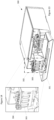
- Figure 13 illustrates an example printer system 300 with an access door 301 in an open position to allow access to an ink tank bay 302 containing at least one ink tank, such as example ink tank 303, for filling or refilling.
- Figure 14 is a magnified view of the ink tank bay 302 illustrating one of the example ink tanks 303 and a cap assembly 304 in a fully opened position.
- the example ink tank 303 and the cap assembly 304 may be similar to the example ink tank 100 and cap assembly 102 described above with reference to Figures 1-12 .
- the cap assembly 304 is attached to the ink tank with a preloaded hinge to rotate the cap assembly 304 from a closed position to an open position when the cap assembly 304 is unlatched.
- the cap assembly 304 of Figure 14 may include a bung to seal the ink tank during a partial rotation of the cap assembly 304 when the cap assembly 304 is unlatched.
- a spring-loaded linkage may be provided and may be connected to a valve in the ink tank.
- An effector may extend from the cap assembly 304 to engage and actuate the spring-loaded linkage when the cap assembly 304 is latched and to disengage from the spring-loaded linkage after the cap assembly 304 is unlatched.
- the spring-loaded linkage opens the valve when engaged with the effector, and closes the valve when disengaged from the effector.
- the bung maintains a tank seal until the internal valve is closed.
- a flowchart illustrates an example method 500 for linking cap and valve actuation in an ink tank.
- the example method includes sealing an ink tank with a cap assembly comprising a bung and an effector, such as cap assembly 102 in Figure 4 illustrating bung 107, and cap assembly 102 in Figure 7 illustrating effector 201 (block 501).
- Example method 500 further includes rotating the cap assembly from a closed position to a first position with a preloaded hinge to close a valve in the ink tank (block 502).
- Figure 10 illustrates cap assembly 102 rotated by hinge 104 to a first, partially rotated position to disengage effector 201 from the external linkage comprising slider 202, external lever arm 203, hinge 204, and sealed spline 205.
- Figure 11 illustrates the internal linkage comprising lever arm 206, valve body 207, and valve seal 209 seated in valve seat 210 to seal (close) the valve.
- example method 500 includes rotating the cap assembly to a second position with the preloaded hinge, where the ink tank is unsealed and the valve in the ink tank remains closed (block 503).
- Figures 12 illustrates cap 102 rotated to a second, fully opened position where the effector 102 is disengaged from the linkage described above, and the linkage is in the same position as in Figure 10 , corresponding to a closed valve
- linking the actuation of the external cap and internal valve of an ink tank during ink filling operations insures that a valve internal to the ink tank is sealed before an external seal is broken and negative backpressure in the cartridge's ink tank is lost.
Landscapes
- Ink Jet (AREA)
- Closures For Containers (AREA)
- Engineering & Computer Science (AREA)
- Mechanical Engineering (AREA)
Description
- Printers are commonplace, whether in a home environment or an office environment. Such printers can include laser printer, inkjet printers or other types. Generally, printers require at least one consumable, such as paper or ink. Ink may be provided for the printers in cartridges that may be replaceable or refillable.
US6367918 discloses a latching device for ink jet cartridges.US 2005/151799 discloses an ink cartridge holder for use in squeezing ink out of an ink cartridge. - The scope of the invention is defined by the appended claims.
- For a more complete understanding of various examples, reference is now made to the following description taken in connection with the accompanying drawings in which:
-
Figure 1 is a side view of an example ink tank; -
Figure 2 is a perspective illustration of an example ink tank with a closed cap; -
Figure 3 is a perspective illustration of an example ink tank with an open cap; -
Figure 4 is a sectional view of an example cap assembly in a closed position; -
Figure 5 is a sectional view of an example cap assembly in a partially opened position; -
Figure 6 is a sectional view of an example cap assembly in a fully opened position; -
Figure 7 is a side view of an example ink tank; -
Figure 8 is a perspective illustration of an example valve linkage; -
Figure 9 is a sectional view of an example ink tank with a closed cap; -
Figure 10 is a side view of an example ink tank with a partially open cap; -
Figure 11 is a sectional view of an example ink tank with a partially open cap; -
Figure 12 is a side view of an example ink tank with a fully opened cap; -
Figure 13 is a perspective illustration of an example printing system; -
Figure 14 is a magnified view of an example ink tank bay in the printing system illustrated inFigure 13 ; and -
Figure 15 is a flowchart illustrating an example method for sequencing internal and external seals. - Bubbler-style ink tanks for inkjet printers require a seal at the ink fill port during printing to create and maintain the negative back pressure required to prevent excessive ink flow due to gravity when the ink supply is located above the print head assembly. Breaking the seal to fill the ink tank may result in ink drool or flooding at the print head assembly.
- To address the issues described above, various examples provide for linking the cap and valve actuations of external and internal seals of an ink tank. The linkage facilitates sealing of a valve in the ink tank before an external seal is broken and negative backpressure in the ink tank is lost. In one example, when an ink tank is opened for filling, the cap of the ink tank is automatically forced to a first, partially opened position by a pre-loaded hinge, while the cap remains sealed and the valve is actuated (i.e., closed). In some examples, the cap includes an effector that actuates the valve through the linkage.
- Accordingly, the present disclosure describes example apparatus, methods and systems to facilitate the linked activation of cap and valve seals of an ink tank. According to the invention, an apparatus is disclosed in claim 1, a related method is disclosed in claim 6 and a related system is disclosed in claim 11. An example apparatus is described below with reference to
Figure 1 . - Referring now to the figures,
Figure 1 illustrates a side view of anexample ink tank 100.Example ink tank 100 includes anink tank body 101, which may be a multi-chambered ink tank as described in greater detail below. Theexample ink tank 100 also includes acap assembly 102 attached to theink tank 100 with a hinge, such ashinge 103 illustrated inFigure 1 , which may be preloaded. In the example illustrated inFigure 1 , thecap assembly 102 is shown in a latched (closed) state.Cap assembly 102 is attached to theexample ink tank 100 by thehinge 103. Hinge 103 may be any type of hinge that constrains the rotation of thecap assembly 102 to a single axis of rotation. In one example,hinge 103 may be an axle engaged with cylindrical bearings extending from thecap assembly 102. In one example,hinge 103 may be preloaded with anelastic band 104 disposed around thehinge 103 to apply an opening force to thecap assembly 102, such that when thecap assembly 102 is unlatched, the opening force applied by theelastic band 104 rotates thecap assembly 102 to a fully opened position and maintains thecap assembly 102 in the fully opened position until the force is overcome by force applied by a user to close thecap assembly 102. -
Example ink tank 100 also includes alatch 105 to hold thecap assembly 102 in a closed position against the opening force applied by theelastic band 104 as illustrated inFigure 1 . Accordingly, thecap assembly 102 is constrained to two stable states: a closed state (closed position) as illustrated inFigure 1 when thelatch 105 is engaged, and a fully opened state (fully opened position) when the latch is released, as described and illustrated below. - For greater clarity in describing the disposition and function of the
elastic band 104,Figure 2 is a perspective illustration of theink cap assembly 102 in the closed position, andFigure 3 is a perspective illustration of theexample ink tank 100 with thecap assembly 102 in the fully opened position. It will be appreciated from these views that theelastic band 104 wraps around the ends of the axle of hinge 103 (as illustrated inFigure 3 ) and under the arms of the hinge 103 (as illustrated inFigure 3 ) to force to thecap assembly 102 to the fully open position as illustrated inFigure 3 . -
Figure 4 is a sectional view of anexample cap assembly 102 illustrating internal details ofcap assembly 102 in the closed position, andFigure 5 is a sectional view illustrating thecap assembly 102 ofFigure 4 in a transient, partially open state after thecap assembly 102 has been unlatched by the operation oflatch 105. As illustrated inFigure 4 , the cap assembly includes acap housing 106, abung 107 retained within thecap housing 106, and aspring 108 disposed between thecap housing 106 and thebung 107. In one example, and without limitation,cap housing 106 may be fabricated from an acetal homopolymer thermoplastic such as Delrin,® and thebung 107 may be fabricated from a natural or synthetic elastic polymer such as natural rubber or silicone rubber. Also shown inFigure 4 are the ink tank body 101 (partial), theelastic band 104, and thelatch 105, previously described. - In the closed (latched) position illustrated in
Figure 4 , thespring 108 is compressed between thecap housing 106 and thebung 107 and applies a sealing force between thebung 107 and theink tank body 101. In one example, thebung 107 may include an O-ring 109 to improve the seal between thebung 107 and theink tank body 101. As shown inFigure 4 , thebung 107 is retained withincap housing 106 by a number of complementary features comprising tabs or protuberances from thebung 107 and openings, cavities or channels in thecap housing 106. These includetab 110 of thebung 107 in achannel 111 of the cap housing (hidden inFigure 4 but visible inFigure 5 ),tab 112 of thebung 107 in opening 113 of thecap housing 106, andcrown 114 of thebung 107 incavity 115 of thecap housing 106. It will be appreciated that these complementary features will allow for relative motion between thecap housing 106 and thebung 107 when thecap assembly 102 is unlatched, as described below. - As noted,
Figure 5 is a sectional view illustrating thecap assembly 102 ofFigure 4 in a transient, partially open state after thecap assembly 102 has been unlatched by the operation oflatch 105. This transient state is achieved by the combined forces ofspring 108 andhinge 104. Whenlatch 105 is released,spring 108 applies a force to push thecap housing 102 away from thebung 107 while maintaining a sealing force between thebung 107 and theink tank body 101. It will be appreciated that this force decreases asspring 108 decompresses and that the relative motion of thecap housing 106 and thebung 107 is limited by the complementary features of thecap assembly 106 and thebung 107 described above. - In the transient state shown in
Figure 5 ,tab 112 is constrained by opening 113, the crown 114 (with spring 108) has moved withincavity 115, andtab 110 has reached the lower bound ofchannel 111, which limits further relative motion between thecap housing 106 and thebung 107. In one example, described in greater detail below, this transient position serves to actuate a valve in the ink tank (using other features of the cap housing 102) to effect a secondary seal in theink tank body 101 before the seal between thebung 107 and theink tank body 101 is broken. After thecap assembly 102 reaches the transient position illustrated inFigure 5 , further motion of thecap assembly 102 is controlled by the force applied to thecap assembly 102 by theelastic band 104. As described previously, this force rotates the cap assembly to a fully open position. -
Figure 6 is a sectional view illustrating thecap assembly 102 ofFigures 4 and5 in the fully open state. In this state, further rotation is limited by interference between asidewall 116 of theink tank body 101 and aflange 117 of the hinge 103 (not visible inFigure 6 ). - Turning now to a description of the secondary sealing mechanism referenced above with respect to the opening of the
cap assembly 102,Figure 7 illustrates the side view of theexample ink tank 100 previously illustrated inFigure 1 . In the example ofFigure 7 , thecap assembly 102 is in the closed (latched) state. In this state, an effector 201 (an extension of cap assembly 102) extends downward from thecap assembly 102 to depress aslider 202, which is retained in a channel in the body of theink tank 100. The slider may be retained by any means known in the art, such as by channels or tabs, for example. In this position, theslider 202 is engaged with a cam onlever arm 203 that is spring loaded by aspring 204, and holds thelever arm 203 in a downward position against the force of thespring 204.Lever arm 203 is fixed to arotatable spline 205 that extends into the interior of theink tank body 101. In one example,spline 205 may be held in place by a snap-ring or c-clip, and sealed by an O-ring or the like as it passes through the wall of theink tank body 101. -
Figure 8 is a perspective illustration of the linkage described above, in isolation, showing additional details not visible inFigure 7 . InFigure 8 , the sealedpinion 205 is fixed to asecond lever arm 206, which in turn is connected to avalve body 207 by apin 208 that is fixed with respect tolever arm 206 and free to rotate with respect tovalve body 207.Valve body 207 includes avalve seal 209 that is configured to provide a seal when seated in avalve seat 210 in the ink tank (seeFigure 9 ). It will be appreciated that in the closed cap configurations illustrated inFigure 7 andFigure 8 , thelever arm 203 is held in a downward rotated position by theslider 202, thatlever arm 206 is held in an upward rotated position by its fixed connection tolever arm 203 viaspline 205, and that the valve assembly comprisingvalve seal 209 andvalve seat 210 is held open. -
Figure 9 is a partial sectional (cutaway) view of theexample ink tank 100, showing internal details of the ink tank and the valve linkage described above in the closed cap configuration. InFigure 9 ,lever arm 206 is in its upward rotated position, which translates throughvalve body 207 to an unseatedvalve seal 209. Also illustrated inFigure 9 is anupper chamber 301 ofink tank body 101, and alower chamber 401 ofink tank body 101, also referred to as a feeder tank. The valve assembly is positioned between theupper chamber 301 and thelower chamber 401 and permits fluid commination between theupper chamber 301 and thelower chamber 401. - Turning now to
Figure 10 , there is illustrated a side view of theexample ink tank 100 with the cap in the transient, partially open state described above. In this transient state, thecap assembly 102 is partially open, such that thecap housing 106 is partially rotated and the bung (107) to ink tank (101) seal is maintained, but the holding force applied byeffector 201 is removed fromslider 202, which allows the force ofspring 204 to rotatelever arm 203 upward (clockwise inFigure 10 ). In one example, the angle of rotation of thecap assembly 102 relative to the closed position may be in the range of approximately 10 to 14 degrees. -
Figure 11 is a partial sectional (cutaway) view of theexample ink tank 100, showing internal details of the ink tank and the valve linkage described above in the transient, partially open cap state. InFigure 11 ,lever arm 206 is rotated downward, which translates throughvalve body 207 toseat valve seal 209 intovalue seat 210, thereby providing a seal betweenupper chamber 301 and lower chamber 401and preventing fluid communication between theupper chamber 301 and thelower chamber 401. -
Figure 12 illustrates theexample ink tank 100 with the cap assembly rotated to its fully opened position under the force applied by theelastic band 104 described above. It will be appreciated that the internal seal betweenvalve seal 209 andvalve seat 210 will be maintained as thecap assembly 102 rotates from the transient position to the fully opened position because theeffector 201 remains disengaged from theslider 202, allowing thespring 204 to hold thelever arm 203 in its upward rotated position. As described above, this position oflever arm 203 corresponds to the seating ofvalve seal 209 invalve seat 210. - The seal between the
upper chamber 301 and thelower chamber 401 isolates the upper chamber to prevent gravitationally induced pressure from causing ink drool at the print head assembly. - From the foregoing description, it will be appreciated that the sequence of events that occurs when the cap is opened is reversible when the
cap assembly 102 is closed by a user. Between the fully opened state and the transient state, the internal valve is closed and theupper chamber 301 ofink tank body 101 is not sealed by thebung 107. When the cap assembly reaches the transient position, the bung (107) seals theupper chamber 301 of ink tank (101) and theeffector 201 engages theslider 202. From the transient position to the closed position, theeffector 201 depressesslider 202, which rotateslever arm 203 downward andlever arm 206 upward to unseatvalve seal 209 fromvalve seat 210, reestablishing fluid communication betweenupper chamber 301 ofink tank body 101 andlower chamber 401 ofink tank body 101. -
Figure 13 illustrates anexample printer system 300 with anaccess door 301 in an open position to allow access to anink tank bay 302 containing at least one ink tank, such asexample ink tank 303, for filling or refilling.Figure 14 is a magnified view of theink tank bay 302 illustrating one of theexample ink tanks 303 and acap assembly 304 in a fully opened position. Theexample ink tank 303 and thecap assembly 304 may be similar to theexample ink tank 100 andcap assembly 102 described above with reference toFigures 1-12 . In this regard, thecap assembly 304 is attached to the ink tank with a preloaded hinge to rotate thecap assembly 304 from a closed position to an open position when thecap assembly 304 is unlatched. Thecap assembly 304 ofFigure 14 may include a bung to seal the ink tank during a partial rotation of thecap assembly 304 when thecap assembly 304 is unlatched. A spring-loaded linkage may be provided and may be connected to a valve in the ink tank. An effector may extend from thecap assembly 304 to engage and actuate the spring-loaded linkage when thecap assembly 304 is latched and to disengage from the spring-loaded linkage after thecap assembly 304 is unlatched. The spring-loaded linkage opens the valve when engaged with the effector, and closes the valve when disengaged from the effector. The bung maintains a tank seal until the internal valve is closed. - Referring now to
Figure 15 , a flowchart illustrates anexample method 500 for linking cap and valve actuation in an ink tank. The example method includes sealing an ink tank with a cap assembly comprising a bung and an effector, such ascap assembly 102 inFigure 4 illustrating bung 107, andcap assembly 102 inFigure 7 illustrating effector 201 (block 501).Example method 500 further includes rotating the cap assembly from a closed position to a first position with a preloaded hinge to close a valve in the ink tank (block 502). For example,Figure 10 illustratescap assembly 102 rotated byhinge 104 to a first, partially rotated position to disengageeffector 201 from the externallinkage comprising slider 202,external lever arm 203, hinge 204, and sealedspline 205.Figure 11 illustrates the internal linkage comprisinglever arm 206,valve body 207, andvalve seal 209 seated invalve seat 210 to seal (close) the valve. Finally,example method 500 includes rotating the cap assembly to a second position with the preloaded hinge, where the ink tank is unsealed and the valve in the ink tank remains closed (block 503). For example,Figures 12 illustratescap 102 rotated to a second, fully opened position where theeffector 102 is disengaged from the linkage described above, and the linkage is in the same position as inFigure 10 , corresponding to a closed valve - Thus, in accordance with various examples described herein, linking the actuation of the external cap and internal valve of an ink tank during ink filling operations insures that a valve internal to the ink tank is sealed before an external seal is broken and negative backpressure in the cartridge's ink tank is lost.
- The foregoing description of various examples has been presented for purposes of illustration and description. The foregoing description is not intended to be exhaustive or limiting to the examples disclosed, and modifications and variations are possible in light of the above teachings or may be acquired from practice of various examples. The examples discussed herein were chosen and described to explain the principles and the nature of various examples of the present disclosure and its practical application to enable one skilled in the art to use the present disclosure in various examples and with various modifications as are suited to the particular use contemplated. The features of the examples described herein may be combined in all possible combinations of methods, apparatus and systems.
- It is also noted herein that while the above describes examples, these descriptions should not be viewed in a limiting sense. Rather, there are several variations and modifications which may be made without departing from the scope as defined in the appended claims.
Claims (11)
- An apparatus, comprising:an ink tank;a cap assembly (102, 304) attached to the ink tank with a preloaded hinge (103) configured to rotate the cap assembly (102, 304) from a closed position to an open position when the cap assembly (102, 304) is unlatched, the cap assembly (102, 304) comprising a bung (107) to seal the ink tank during a partial rotation of the cap assembly (102, 304) when the cap assembly (102, 304) is unlatched;a spring-loaded linkage connected to a valve in the ink tank, wherein the valve provides a secondary seal in the ink tank body (101);an effector (201) extending from the cap assembly (102, 304) configured to engage and actuate the spring-loaded linkage when the cap assembly (102, 304) is latched and configured to disengage from the spring-loaded linkage after the cap assembly (102, 304) is unlatched, wherein the spring-loaded linkage is configured to open the valve when engaged with the effector (201), and close the valve when disengaged from the effector (201), andwherein the bung (107) is configured to maintain a tank seal during rotation of the cap assembly (102, 304) from the closed position to the open position until the valve is closed to effect the secondary seal.
- The apparatus of claim 1, wherein the ink tank comprises an upper chamber (301) and a lower chamber (401) and the valve therebetween, the valve comprising a valve body (207), a valve seal (209) and a valve seat (210).
- The apparatus of claim 2, wherein the spring-loaded linkage comprises:a first lever arm (206) internal to the ink tank, coupled to the valve;a second lever arm (203), external to the ink tank;a sealed spline (205) fixed to the first lever arm (206) and the second lever arm (203);a spring (108, 204) coupled to the second lever arm (203); anda slider (202) coupled to the second lever arm (203) to engage the effector (201).
- The apparatus of claim 3, wherein the spring (108, 204) is operative to bias the valve to a closed position when the effector (201) is disengaged with the slider (202), wherein fluid communication between the upper chamber (301) and the lower chamber (401) is prevented.
- The apparatus of claim 3, wherein the slider (202) is operative to open the valve when the effector (201) is engaged with the slider (202), wherein fluid communication between the upper chamber (301) and the lower chamber (401) is enabled.
- A method, comprising:sealing an ink tank with a cap assembly (102, 304) comprising a bung (107) and an effector (201);rotating the cap assembly (102, 304) from a closed position to a first position with a preloaded hinge (103), wherein a valve in the ink tank is closed to effect a secondary seal of the ink tank during rotation of the cap assembly (102, 304) and before the seal between the bung (107) and a body of the ink tank is broken and the valve actuation is linked to the cap assembly actuation such that the effector (201) actuates the valve; androtating the cap assembly (102, 304) to a second position with the preloaded hinge (103), wherein the ink tank is unsealed and the valve in the ink tank remains closed.
- The method of claim 6, further comprising:rotating the cap assembly (102, 304) from the second position to the first position, wherein the ink tank is resealed and the valve remains closed;rotating the cap assembly (102, 304) from the first position to the closed position, wherein the valve is opened and the ink tank remains sealed
- The method of claim 6, wherein when the cap assembly (102, 304) is in the closed position, the effector (201) engages a valve linkage that opens the valve.
- The method of claim 8, wherein when the cap assembly (102, 304) is between the first position and the second position, the effector (201) disengages the valve linkage.
- The method of claim 9, wherein the valve is biased to a closed position by the valve linkage.
- A system, comprising:an ink tank bay (302);at least one apparatus according to any of claims 1 to 5, wherein at least one ink tank is installed in the ink tank bay (302).
Applications Claiming Priority (1)
| Application Number | Priority Date | Filing Date | Title |
|---|---|---|---|
| PCT/US2017/057742 WO2019078898A1 (en) | 2017-10-20 | 2017-10-20 | Ink tank cap and valve linkage |
Publications (3)
| Publication Number | Publication Date |
|---|---|
| EP3697620A1 EP3697620A1 (en) | 2020-08-26 |
| EP3697620A4 EP3697620A4 (en) | 2021-05-05 |
| EP3697620B1 true EP3697620B1 (en) | 2023-07-26 |
Family
ID=66173365
Family Applications (1)
| Application Number | Title | Priority Date | Filing Date |
|---|---|---|---|
| EP17928844.4A Active EP3697620B1 (en) | 2017-10-20 | 2017-10-20 | Ink tank cap and valve linkage |
Country Status (4)
| Country | Link |
|---|---|
| US (1) | US11046102B2 (en) |
| EP (1) | EP3697620B1 (en) |
| CN (1) | CN111212741B (en) |
| WO (1) | WO2019078898A1 (en) |
Families Citing this family (4)
| Publication number | Priority date | Publication date | Assignee | Title |
|---|---|---|---|---|
| US11305548B2 (en) * | 2017-10-20 | 2022-04-19 | Hewlett-Packard Development Company, L.P. | Cap seal and valve sequencing |
| JP2022057832A (en) | 2020-09-30 | 2022-04-11 | ブラザー工業株式会社 | Ink tank and image recording device |
| JP2022057839A (en) * | 2020-09-30 | 2022-04-11 | ブラザー工業株式会社 | Ink tank and image recording device |
| JP2022057838A (en) * | 2020-09-30 | 2022-04-11 | ブラザー工業株式会社 | Ink tank and image recording apparatus |
Family Cites Families (17)
| Publication number | Priority date | Publication date | Assignee | Title |
|---|---|---|---|---|
| US6367918B1 (en) | 1994-10-31 | 2002-04-09 | Hewlett-Packard Company | Unitary latching device for secure positioning of print cartridge during printing, priming and replenishment |
| US5825387A (en) | 1995-04-27 | 1998-10-20 | Hewlett-Packard Company | Ink supply for an ink-jet printer |
| JP3713632B2 (en) * | 1994-12-28 | 2005-11-09 | 富士写真フイルム株式会社 | Ink cartridge and inkjet printer |
| US7114801B2 (en) | 1995-04-27 | 2006-10-03 | Hewlett-Packard Development Company, L.P. | Method and apparatus for providing ink to an ink jet printing system |
| US6948798B2 (en) * | 2001-05-31 | 2005-09-27 | Hewlett-Packard Development Company, L.P. | Method and apparatus for horizontally loading and unloading an ink-jet print cartridge from a carriage |
| US6481829B1 (en) * | 2001-09-18 | 2002-11-19 | Lexmark International, Inc. | Manually actuated carrier latch mechanism |
| CA2453170C (en) | 2002-12-20 | 2012-02-21 | Mold-Masters Limited | Lateral gating injection molding apparatus |
| DE102004001750B3 (en) | 2004-01-12 | 2005-05-25 | Technotrans Ag | Ink cartridge container for supplying the inking system of a printing machine with ink comprises a pivot drive that in a first movement phase closes a lid and in a second movement phase locks the lid and activates an air valve |
| JP4821430B2 (en) | 2006-05-16 | 2011-11-24 | ブラザー工業株式会社 | Ink jet printer apparatus and ink cartridge mounting method |
| JP4809178B2 (en) | 2006-09-29 | 2011-11-09 | 富士フイルム株式会社 | Liquid ejection apparatus and liquid supply method |
| DE102007001084A1 (en) | 2006-12-12 | 2008-06-19 | Pelikan Hardcopy Production Ag | Ink cartridge, for mounting below) inkjet on printing head of ink jet printer, has vent aperture with valve coupled to valve on ink outlet, both valves opening automatically when cartridge is inserted |
| TWI321525B (en) | 2007-01-02 | 2010-03-11 | Qisda Corp | Inkjet printers |
| JP4770768B2 (en) * | 2007-03-23 | 2011-09-14 | ブラザー工業株式会社 | Droplet ejection device and subtank for droplet ejection device |
| CN201176026Y (en) | 2008-03-21 | 2009-01-07 | 珠海中润靖杰打印机耗材有限公司 | Ink-jet box |
| JP5298780B2 (en) | 2008-11-04 | 2013-09-25 | セイコーエプソン株式会社 | Liquid supply apparatus, printing apparatus, and control method of liquid supply apparatus |
| CN201889955U (en) | 2010-10-18 | 2011-07-06 | 泰金宝电通股份有限公司 | Automatic uncovering device and printer with the same |
| US9067424B1 (en) * | 2014-01-09 | 2015-06-30 | Riso Kagaku Corporation | Ink cartridge and mount/demount mechanism for the same |
-
2017
- 2017-10-20 CN CN201780095941.XA patent/CN111212741B/en active Active
- 2017-10-20 US US16/499,255 patent/US11046102B2/en active Active
- 2017-10-20 EP EP17928844.4A patent/EP3697620B1/en active Active
- 2017-10-20 WO PCT/US2017/057742 patent/WO2019078898A1/en unknown
Also Published As
| Publication number | Publication date |
|---|---|
| US11046102B2 (en) | 2021-06-29 |
| EP3697620A4 (en) | 2021-05-05 |
| WO2019078898A1 (en) | 2019-04-25 |
| EP3697620A1 (en) | 2020-08-26 |
| CN111212741B (en) | 2022-05-27 |
| US20200238742A1 (en) | 2020-07-30 |
| CN111212741A (en) | 2020-05-29 |
Similar Documents
| Publication | Publication Date | Title |
|---|---|---|
| EP3697620B1 (en) | Ink tank cap and valve linkage | |
| EP0878309B1 (en) | Refill assembly for printer ink cartridges | |
| EP0778147B1 (en) | Apparatus and method for filling ink cartridges | |
| EP3623159B1 (en) | Ink jet recording apparatus | |
| US7114801B2 (en) | Method and apparatus for providing ink to an ink jet printing system | |
| US20020036680A1 (en) | Method and apparatus for providing ink to an ink jet printing system | |
| US5933173A (en) | Holder for refilling and preserving an ink jet printhead | |
| US11220111B2 (en) | Ink cartridge caps | |
| US11305548B2 (en) | Cap seal and valve sequencing | |
| JP2017515749A (en) | Fuel tank assembly with trigger vent | |
| US5821967A (en) | Holder for refilling an ink jet printhead | |
| US10654284B2 (en) | Fluid storage device with multi-position seal assembly | |
| JP2002103642A (en) | Ink cartridge for ink jet recorder | |
| US7303267B2 (en) | Actuator for automatic ink refill system | |
| WO2006093472A1 (en) | Ink reservoir | |
| CN212636919U (en) | Ink replenishing container and ink device | |
| JP4144503B2 (en) | Ink cartridge vacuum sealing method and vacuum sealed product | |
| JPH08290577A (en) | Ink tank | |
| CN220031525U (en) | Ink supply container | |
| US11541663B2 (en) | Liquid ejection apparatus and liquid refill container | |
| JP6327015B2 (en) | Liquid cartridge and liquid cartridge cap mounting method | |
| US11584128B2 (en) | Printhead priming and venting | |
| WO2020106278A1 (en) | Fluid supply valve |
Legal Events
| Date | Code | Title | Description |
|---|---|---|---|
| STAA | Information on the status of an ep patent application or granted ep patent |
Free format text: STATUS: THE INTERNATIONAL PUBLICATION HAS BEEN MADE |
|
| PUAI | Public reference made under article 153(3) epc to a published international application that has entered the european phase |
Free format text: ORIGINAL CODE: 0009012 |
|
| STAA | Information on the status of an ep patent application or granted ep patent |
Free format text: STATUS: REQUEST FOR EXAMINATION WAS MADE |
|
| 17P | Request for examination filed |
Effective date: 20200330 |
|
| AK | Designated contracting states |
Kind code of ref document: A1 Designated state(s): AL AT BE BG CH CY CZ DE DK EE ES FI FR GB GR HR HU IE IS IT LI LT LU LV MC MK MT NL NO PL PT RO RS SE SI SK SM TR |
|
| AX | Request for extension of the european patent |
Extension state: BA ME |
|
| DAV | Request for validation of the european patent (deleted) | ||
| DAX | Request for extension of the european patent (deleted) | ||
| A4 | Supplementary search report drawn up and despatched |
Effective date: 20210408 |
|
| RIC1 | Information provided on ipc code assigned before grant |
Ipc: B41L 27/04 20060101AFI20210331BHEP Ipc: B65D 43/16 20060101ALI20210331BHEP |
|
| REG | Reference to a national code |
Ref document number: 602017071990 Country of ref document: DE Ref country code: DE Ref legal event code: R079 Free format text: PREVIOUS MAIN CLASS: B41L0027040000 Ipc: B41J0002175000 |
|
| GRAP | Despatch of communication of intention to grant a patent |
Free format text: ORIGINAL CODE: EPIDOSNIGR1 |
|
| STAA | Information on the status of an ep patent application or granted ep patent |
Free format text: STATUS: GRANT OF PATENT IS INTENDED |
|
| RIC1 | Information provided on ipc code assigned before grant |
Ipc: B41J 1/00 20060101ALI20230209BHEP Ipc: B41L 27/04 20060101ALI20230209BHEP Ipc: B41J 2/175 20060101AFI20230209BHEP |
|
| INTG | Intention to grant announced |
Effective date: 20230313 |
|
| GRAS | Grant fee paid |
Free format text: ORIGINAL CODE: EPIDOSNIGR3 |
|
| GRAA | (expected) grant |
Free format text: ORIGINAL CODE: 0009210 |
|
| STAA | Information on the status of an ep patent application or granted ep patent |
Free format text: STATUS: THE PATENT HAS BEEN GRANTED |
|
| AK | Designated contracting states |
Kind code of ref document: B1 Designated state(s): AL AT BE BG CH CY CZ DE DK EE ES FI FR GB GR HR HU IE IS IT LI LT LU LV MC MK MT NL NO PL PT RO RS SE SI SK SM TR |
|
| REG | Reference to a national code |
Ref country code: CH Ref legal event code: EP |
|
| REG | Reference to a national code |
Ref country code: IE Ref legal event code: FG4D |
|
| REG | Reference to a national code |
Ref country code: DE Ref legal event code: R096 Ref document number: 602017071990 Country of ref document: DE |
|
| REG | Reference to a national code |
Ref country code: LT Ref legal event code: MG9D |
|
| REG | Reference to a national code |
Ref country code: NL Ref legal event code: MP Effective date: 20230726 |
|
| REG | Reference to a national code |
Ref country code: AT Ref legal event code: MK05 Ref document number: 1591546 Country of ref document: AT Kind code of ref document: T Effective date: 20230726 |
|
| PG25 | Lapsed in a contracting state [announced via postgrant information from national office to epo] |
Ref country code: NL Free format text: LAPSE BECAUSE OF FAILURE TO SUBMIT A TRANSLATION OF THE DESCRIPTION OR TO PAY THE FEE WITHIN THE PRESCRIBED TIME-LIMIT Effective date: 20230726 |
|
| PG25 | Lapsed in a contracting state [announced via postgrant information from national office to epo] |
Ref country code: GR Free format text: LAPSE BECAUSE OF FAILURE TO SUBMIT A TRANSLATION OF THE DESCRIPTION OR TO PAY THE FEE WITHIN THE PRESCRIBED TIME-LIMIT Effective date: 20231027 |
|
| PG25 | Lapsed in a contracting state [announced via postgrant information from national office to epo] |
Ref country code: IS Free format text: LAPSE BECAUSE OF FAILURE TO SUBMIT A TRANSLATION OF THE DESCRIPTION OR TO PAY THE FEE WITHIN THE PRESCRIBED TIME-LIMIT Effective date: 20231126 |
|
| PG25 | Lapsed in a contracting state [announced via postgrant information from national office to epo] |
Ref country code: SE Free format text: LAPSE BECAUSE OF FAILURE TO SUBMIT A TRANSLATION OF THE DESCRIPTION OR TO PAY THE FEE WITHIN THE PRESCRIBED TIME-LIMIT Effective date: 20230726 Ref country code: RS Free format text: LAPSE BECAUSE OF FAILURE TO SUBMIT A TRANSLATION OF THE DESCRIPTION OR TO PAY THE FEE WITHIN THE PRESCRIBED TIME-LIMIT Effective date: 20230726 Ref country code: PT Free format text: LAPSE BECAUSE OF FAILURE TO SUBMIT A TRANSLATION OF THE DESCRIPTION OR TO PAY THE FEE WITHIN THE PRESCRIBED TIME-LIMIT Effective date: 20231127 Ref country code: NO Free format text: LAPSE BECAUSE OF FAILURE TO SUBMIT A TRANSLATION OF THE DESCRIPTION OR TO PAY THE FEE WITHIN THE PRESCRIBED TIME-LIMIT Effective date: 20231026 Ref country code: LV Free format text: LAPSE BECAUSE OF FAILURE TO SUBMIT A TRANSLATION OF THE DESCRIPTION OR TO PAY THE FEE WITHIN THE PRESCRIBED TIME-LIMIT Effective date: 20230726 Ref country code: LT Free format text: LAPSE BECAUSE OF FAILURE TO SUBMIT A TRANSLATION OF THE DESCRIPTION OR TO PAY THE FEE WITHIN THE PRESCRIBED TIME-LIMIT Effective date: 20230726 Ref country code: IS Free format text: LAPSE BECAUSE OF FAILURE TO SUBMIT A TRANSLATION OF THE DESCRIPTION OR TO PAY THE FEE WITHIN THE PRESCRIBED TIME-LIMIT Effective date: 20231126 Ref country code: HR Free format text: LAPSE BECAUSE OF FAILURE TO SUBMIT A TRANSLATION OF THE DESCRIPTION OR TO PAY THE FEE WITHIN THE PRESCRIBED TIME-LIMIT Effective date: 20230726 Ref country code: GR Free format text: LAPSE BECAUSE OF FAILURE TO SUBMIT A TRANSLATION OF THE DESCRIPTION OR TO PAY THE FEE WITHIN THE PRESCRIBED TIME-LIMIT Effective date: 20231027 Ref country code: FI Free format text: LAPSE BECAUSE OF FAILURE TO SUBMIT A TRANSLATION OF THE DESCRIPTION OR TO PAY THE FEE WITHIN THE PRESCRIBED TIME-LIMIT Effective date: 20230726 Ref country code: AT Free format text: LAPSE BECAUSE OF FAILURE TO SUBMIT A TRANSLATION OF THE DESCRIPTION OR TO PAY THE FEE WITHIN THE PRESCRIBED TIME-LIMIT Effective date: 20230726 |
|
| PGFP | Annual fee paid to national office [announced via postgrant information from national office to epo] |
Ref country code: DE Payment date: 20230920 Year of fee payment: 7 |
|
| PG25 | Lapsed in a contracting state [announced via postgrant information from national office to epo] |
Ref country code: PL Free format text: LAPSE BECAUSE OF FAILURE TO SUBMIT A TRANSLATION OF THE DESCRIPTION OR TO PAY THE FEE WITHIN THE PRESCRIBED TIME-LIMIT Effective date: 20230726 |
|
| PG25 | Lapsed in a contracting state [announced via postgrant information from national office to epo] |
Ref country code: ES Free format text: LAPSE BECAUSE OF FAILURE TO SUBMIT A TRANSLATION OF THE DESCRIPTION OR TO PAY THE FEE WITHIN THE PRESCRIBED TIME-LIMIT Effective date: 20230726 |
|
| REG | Reference to a national code |
Ref country code: DE Ref legal event code: R097 Ref document number: 602017071990 Country of ref document: DE |
|
| PG25 | Lapsed in a contracting state [announced via postgrant information from national office to epo] |
Ref country code: SM Free format text: LAPSE BECAUSE OF FAILURE TO SUBMIT A TRANSLATION OF THE DESCRIPTION OR TO PAY THE FEE WITHIN THE PRESCRIBED TIME-LIMIT Effective date: 20230726 Ref country code: RO Free format text: LAPSE BECAUSE OF FAILURE TO SUBMIT A TRANSLATION OF THE DESCRIPTION OR TO PAY THE FEE WITHIN THE PRESCRIBED TIME-LIMIT Effective date: 20230726 Ref country code: ES Free format text: LAPSE BECAUSE OF FAILURE TO SUBMIT A TRANSLATION OF THE DESCRIPTION OR TO PAY THE FEE WITHIN THE PRESCRIBED TIME-LIMIT Effective date: 20230726 Ref country code: EE Free format text: LAPSE BECAUSE OF FAILURE TO SUBMIT A TRANSLATION OF THE DESCRIPTION OR TO PAY THE FEE WITHIN THE PRESCRIBED TIME-LIMIT Effective date: 20230726 Ref country code: DK Free format text: LAPSE BECAUSE OF FAILURE TO SUBMIT A TRANSLATION OF THE DESCRIPTION OR TO PAY THE FEE WITHIN THE PRESCRIBED TIME-LIMIT Effective date: 20230726 Ref country code: CZ Free format text: LAPSE BECAUSE OF FAILURE TO SUBMIT A TRANSLATION OF THE DESCRIPTION OR TO PAY THE FEE WITHIN THE PRESCRIBED TIME-LIMIT Effective date: 20230726 Ref country code: SK Free format text: LAPSE BECAUSE OF FAILURE TO SUBMIT A TRANSLATION OF THE DESCRIPTION OR TO PAY THE FEE WITHIN THE PRESCRIBED TIME-LIMIT Effective date: 20230726 |
|
| PG25 | Lapsed in a contracting state [announced via postgrant information from national office to epo] |
Ref country code: IT Free format text: LAPSE BECAUSE OF FAILURE TO SUBMIT A TRANSLATION OF THE DESCRIPTION OR TO PAY THE FEE WITHIN THE PRESCRIBED TIME-LIMIT Effective date: 20230726 Ref country code: MC Free format text: LAPSE BECAUSE OF FAILURE TO SUBMIT A TRANSLATION OF THE DESCRIPTION OR TO PAY THE FEE WITHIN THE PRESCRIBED TIME-LIMIT Effective date: 20230726 |
|
| PLBE | No opposition filed within time limit |
Free format text: ORIGINAL CODE: 0009261 |
|
| REG | Reference to a national code |
Ref country code: CH Ref legal event code: PL |
|
| STAA | Information on the status of an ep patent application or granted ep patent |
Free format text: STATUS: NO OPPOSITION FILED WITHIN TIME LIMIT |
|
| REG | Reference to a national code |
Ref country code: BE Ref legal event code: MM Effective date: 20231031 |
|
| PG25 | Lapsed in a contracting state [announced via postgrant information from national office to epo] |
Ref country code: LU Free format text: LAPSE BECAUSE OF NON-PAYMENT OF DUE FEES Effective date: 20231020 |
|
| GBPC | Gb: european patent ceased through non-payment of renewal fee |
Effective date: 20231026 |
|
| PG25 | Lapsed in a contracting state [announced via postgrant information from national office to epo] |
Ref country code: LU Free format text: LAPSE BECAUSE OF NON-PAYMENT OF DUE FEES Effective date: 20231020 |
|
| 26N | No opposition filed |
Effective date: 20240429 |
|
| PG25 | Lapsed in a contracting state [announced via postgrant information from national office to epo] |
Ref country code: GB Free format text: LAPSE BECAUSE OF NON-PAYMENT OF DUE FEES Effective date: 20231026 |
|
| PG25 | Lapsed in a contracting state [announced via postgrant information from national office to epo] |
Ref country code: CH Free format text: LAPSE BECAUSE OF NON-PAYMENT OF DUE FEES Effective date: 20231031 |
|
| PG25 | Lapsed in a contracting state [announced via postgrant information from national office to epo] |
Ref country code: GB Free format text: LAPSE BECAUSE OF NON-PAYMENT OF DUE FEES Effective date: 20231026 Ref country code: FR Free format text: LAPSE BECAUSE OF NON-PAYMENT OF DUE FEES Effective date: 20231031 Ref country code: CH Free format text: LAPSE BECAUSE OF NON-PAYMENT OF DUE FEES Effective date: 20231031 Ref country code: SI Free format text: LAPSE BECAUSE OF FAILURE TO SUBMIT A TRANSLATION OF THE DESCRIPTION OR TO PAY THE FEE WITHIN THE PRESCRIBED TIME-LIMIT Effective date: 20230726 |
|
| PG25 | Lapsed in a contracting state [announced via postgrant information from national office to epo] |
Ref country code: BE Free format text: LAPSE BECAUSE OF NON-PAYMENT OF DUE FEES Effective date: 20231031 |
|
| PG25 | Lapsed in a contracting state [announced via postgrant information from national office to epo] |
Ref country code: IE Free format text: LAPSE BECAUSE OF NON-PAYMENT OF DUE FEES Effective date: 20231020 |