EP3697594B1 - Tête d'impression pour imprimante 3d - Google Patents
Tête d'impression pour imprimante 3d Download PDFInfo
- Publication number
- EP3697594B1 EP3697594B1 EP18789387.0A EP18789387A EP3697594B1 EP 3697594 B1 EP3697594 B1 EP 3697594B1 EP 18789387 A EP18789387 A EP 18789387A EP 3697594 B1 EP3697594 B1 EP 3697594B1
- Authority
- EP
- European Patent Office
- Prior art keywords
- piston
- print head
- section
- guide surface
- zone
- Prior art date
- Legal status (The legal status is an assumption and is not a legal conclusion. Google has not performed a legal analysis and makes no representation as to the accuracy of the status listed.)
- Active
Links
- 239000007791 liquid phase Substances 0.000 claims description 12
- 239000002994 raw material Substances 0.000 claims 3
- 239000007858 starting material Substances 0.000 description 24
- 239000008187 granular material Substances 0.000 description 23
- 239000000463 material Substances 0.000 description 15
- 238000010438 heat treatment Methods 0.000 description 8
- 238000001816 cooling Methods 0.000 description 7
- 239000002826 coolant Substances 0.000 description 4
- 238000011161 development Methods 0.000 description 3
- 230000018109 developmental process Effects 0.000 description 3
- 230000000694 effects Effects 0.000 description 3
- 230000004992 fission Effects 0.000 description 3
- 239000011344 liquid material Substances 0.000 description 3
- 238000002844 melting Methods 0.000 description 3
- 230000008018 melting Effects 0.000 description 3
- 229920000642 polymer Polymers 0.000 description 3
- 239000000047 product Substances 0.000 description 3
- 239000007787 solid Substances 0.000 description 3
- 230000006835 compression Effects 0.000 description 2
- 238000007906 compression Methods 0.000 description 2
- 238000000354 decomposition reaction Methods 0.000 description 2
- 238000011156 evaluation Methods 0.000 description 2
- 239000007789 gas Substances 0.000 description 2
- 238000012423 maintenance Methods 0.000 description 2
- 239000012815 thermoplastic material Substances 0.000 description 2
- 206010053615 Thermal burn Diseases 0.000 description 1
- 239000012080 ambient air Substances 0.000 description 1
- 238000005452 bending Methods 0.000 description 1
- 238000009833 condensation Methods 0.000 description 1
- 230000005494 condensation Effects 0.000 description 1
- 238000011109 contamination Methods 0.000 description 1
- 230000007423 decrease Effects 0.000 description 1
- 230000008021 deposition Effects 0.000 description 1
- 238000002845 discoloration Methods 0.000 description 1
- 239000002360 explosive Substances 0.000 description 1
- 238000001125 extrusion Methods 0.000 description 1
- 238000005187 foaming Methods 0.000 description 1
- 239000012535 impurity Substances 0.000 description 1
- 238000005259 measurement Methods 0.000 description 1
- 238000000034 method Methods 0.000 description 1
- 238000002156 mixing Methods 0.000 description 1
- 239000000203 mixture Substances 0.000 description 1
- 238000013021 overheating Methods 0.000 description 1
- 239000002245 particle Substances 0.000 description 1
- 230000035515 penetration Effects 0.000 description 1
- 239000012071 phase Substances 0.000 description 1
- 239000004033 plastic Substances 0.000 description 1
- 229920003023 plastic Polymers 0.000 description 1
- 239000011265 semifinished product Substances 0.000 description 1
- 238000007493 shaping process Methods 0.000 description 1
- 239000007790 solid phase Substances 0.000 description 1
- 239000000126 substance Substances 0.000 description 1
- 230000008646 thermal stress Effects 0.000 description 1
- 230000032258 transport Effects 0.000 description 1
- 238000009423 ventilation Methods 0.000 description 1
- XLYOFNOQVPJJNP-UHFFFAOYSA-N water Substances O XLYOFNOQVPJJNP-UHFFFAOYSA-N 0.000 description 1
Images


Classifications
-
- B—PERFORMING OPERATIONS; TRANSPORTING
- B29—WORKING OF PLASTICS; WORKING OF SUBSTANCES IN A PLASTIC STATE IN GENERAL
- B29C—SHAPING OR JOINING OF PLASTICS; SHAPING OF MATERIAL IN A PLASTIC STATE, NOT OTHERWISE PROVIDED FOR; AFTER-TREATMENT OF THE SHAPED PRODUCTS, e.g. REPAIRING
- B29C64/00—Additive manufacturing, i.e. manufacturing of three-dimensional [3D] objects by additive deposition, additive agglomeration or additive layering, e.g. by 3D printing, stereolithography or selective laser sintering
- B29C64/20—Apparatus for additive manufacturing; Details thereof or accessories therefor
- B29C64/205—Means for applying layers
- B29C64/209—Heads; Nozzles
-
- B—PERFORMING OPERATIONS; TRANSPORTING
- B29—WORKING OF PLASTICS; WORKING OF SUBSTANCES IN A PLASTIC STATE IN GENERAL
- B29C—SHAPING OR JOINING OF PLASTICS; SHAPING OF MATERIAL IN A PLASTIC STATE, NOT OTHERWISE PROVIDED FOR; AFTER-TREATMENT OF THE SHAPED PRODUCTS, e.g. REPAIRING
- B29C48/00—Extrusion moulding, i.e. expressing the moulding material through a die or nozzle which imparts the desired form; Apparatus therefor
- B29C48/02—Small extruding apparatus, e.g. handheld, toy or laboratory extruders
-
- B—PERFORMING OPERATIONS; TRANSPORTING
- B29—WORKING OF PLASTICS; WORKING OF SUBSTANCES IN A PLASTIC STATE IN GENERAL
- B29C—SHAPING OR JOINING OF PLASTICS; SHAPING OF MATERIAL IN A PLASTIC STATE, NOT OTHERWISE PROVIDED FOR; AFTER-TREATMENT OF THE SHAPED PRODUCTS, e.g. REPAIRING
- B29C48/00—Extrusion moulding, i.e. expressing the moulding material through a die or nozzle which imparts the desired form; Apparatus therefor
- B29C48/25—Component parts, details or accessories; Auxiliary operations
- B29C48/266—Means for allowing relative movements between the apparatus parts, e.g. for twisting the extruded article or for moving the die along a surface to be coated
-
- B—PERFORMING OPERATIONS; TRANSPORTING
- B29—WORKING OF PLASTICS; WORKING OF SUBSTANCES IN A PLASTIC STATE IN GENERAL
- B29C—SHAPING OR JOINING OF PLASTICS; SHAPING OF MATERIAL IN A PLASTIC STATE, NOT OTHERWISE PROVIDED FOR; AFTER-TREATMENT OF THE SHAPED PRODUCTS, e.g. REPAIRING
- B29C48/00—Extrusion moulding, i.e. expressing the moulding material through a die or nozzle which imparts the desired form; Apparatus therefor
- B29C48/25—Component parts, details or accessories; Auxiliary operations
- B29C48/92—Measuring, controlling or regulating
-
- B—PERFORMING OPERATIONS; TRANSPORTING
- B29—WORKING OF PLASTICS; WORKING OF SUBSTANCES IN A PLASTIC STATE IN GENERAL
- B29C—SHAPING OR JOINING OF PLASTICS; SHAPING OF MATERIAL IN A PLASTIC STATE, NOT OTHERWISE PROVIDED FOR; AFTER-TREATMENT OF THE SHAPED PRODUCTS, e.g. REPAIRING
- B29C64/00—Additive manufacturing, i.e. manufacturing of three-dimensional [3D] objects by additive deposition, additive agglomeration or additive layering, e.g. by 3D printing, stereolithography or selective laser sintering
- B29C64/10—Processes of additive manufacturing
- B29C64/106—Processes of additive manufacturing using only liquids or viscous materials, e.g. depositing a continuous bead of viscous material
- B29C64/118—Processes of additive manufacturing using only liquids or viscous materials, e.g. depositing a continuous bead of viscous material using filamentary material being melted, e.g. fused deposition modelling [FDM]
-
- B—PERFORMING OPERATIONS; TRANSPORTING
- B29—WORKING OF PLASTICS; WORKING OF SUBSTANCES IN A PLASTIC STATE IN GENERAL
- B29C—SHAPING OR JOINING OF PLASTICS; SHAPING OF MATERIAL IN A PLASTIC STATE, NOT OTHERWISE PROVIDED FOR; AFTER-TREATMENT OF THE SHAPED PRODUCTS, e.g. REPAIRING
- B29C64/00—Additive manufacturing, i.e. manufacturing of three-dimensional [3D] objects by additive deposition, additive agglomeration or additive layering, e.g. by 3D printing, stereolithography or selective laser sintering
- B29C64/20—Apparatus for additive manufacturing; Details thereof or accessories therefor
- B29C64/295—Heating elements
-
- B—PERFORMING OPERATIONS; TRANSPORTING
- B29—WORKING OF PLASTICS; WORKING OF SUBSTANCES IN A PLASTIC STATE IN GENERAL
- B29C—SHAPING OR JOINING OF PLASTICS; SHAPING OF MATERIAL IN A PLASTIC STATE, NOT OTHERWISE PROVIDED FOR; AFTER-TREATMENT OF THE SHAPED PRODUCTS, e.g. REPAIRING
- B29C64/00—Additive manufacturing, i.e. manufacturing of three-dimensional [3D] objects by additive deposition, additive agglomeration or additive layering, e.g. by 3D printing, stereolithography or selective laser sintering
- B29C64/30—Auxiliary operations or equipment
- B29C64/307—Handling of material to be used in additive manufacturing
- B29C64/321—Feeding
-
- B—PERFORMING OPERATIONS; TRANSPORTING
- B29—WORKING OF PLASTICS; WORKING OF SUBSTANCES IN A PLASTIC STATE IN GENERAL
- B29C—SHAPING OR JOINING OF PLASTICS; SHAPING OF MATERIAL IN A PLASTIC STATE, NOT OTHERWISE PROVIDED FOR; AFTER-TREATMENT OF THE SHAPED PRODUCTS, e.g. REPAIRING
- B29C64/00—Additive manufacturing, i.e. manufacturing of three-dimensional [3D] objects by additive deposition, additive agglomeration or additive layering, e.g. by 3D printing, stereolithography or selective laser sintering
- B29C64/30—Auxiliary operations or equipment
- B29C64/364—Conditioning of environment
-
- B—PERFORMING OPERATIONS; TRANSPORTING
- B29—WORKING OF PLASTICS; WORKING OF SUBSTANCES IN A PLASTIC STATE IN GENERAL
- B29C—SHAPING OR JOINING OF PLASTICS; SHAPING OF MATERIAL IN A PLASTIC STATE, NOT OTHERWISE PROVIDED FOR; AFTER-TREATMENT OF THE SHAPED PRODUCTS, e.g. REPAIRING
- B29C64/00—Additive manufacturing, i.e. manufacturing of three-dimensional [3D] objects by additive deposition, additive agglomeration or additive layering, e.g. by 3D printing, stereolithography or selective laser sintering
- B29C64/30—Auxiliary operations or equipment
- B29C64/386—Data acquisition or data processing for additive manufacturing
- B29C64/393—Data acquisition or data processing for additive manufacturing for controlling or regulating additive manufacturing processes
-
- B—PERFORMING OPERATIONS; TRANSPORTING
- B33—ADDITIVE MANUFACTURING TECHNOLOGY
- B33Y—ADDITIVE MANUFACTURING, i.e. MANUFACTURING OF THREE-DIMENSIONAL [3-D] OBJECTS BY ADDITIVE DEPOSITION, ADDITIVE AGGLOMERATION OR ADDITIVE LAYERING, e.g. BY 3-D PRINTING, STEREOLITHOGRAPHY OR SELECTIVE LASER SINTERING
- B33Y30/00—Apparatus for additive manufacturing; Details thereof or accessories therefor
-
- B—PERFORMING OPERATIONS; TRANSPORTING
- B29—WORKING OF PLASTICS; WORKING OF SUBSTANCES IN A PLASTIC STATE IN GENERAL
- B29C—SHAPING OR JOINING OF PLASTICS; SHAPING OF MATERIAL IN A PLASTIC STATE, NOT OTHERWISE PROVIDED FOR; AFTER-TREATMENT OF THE SHAPED PRODUCTS, e.g. REPAIRING
- B29C48/00—Extrusion moulding, i.e. expressing the moulding material through a die or nozzle which imparts the desired form; Apparatus therefor
- B29C48/03—Extrusion moulding, i.e. expressing the moulding material through a die or nozzle which imparts the desired form; Apparatus therefor characterised by the shape of the extruded material at extrusion
- B29C48/05—Filamentary, e.g. strands
-
- B—PERFORMING OPERATIONS; TRANSPORTING
- B29—WORKING OF PLASTICS; WORKING OF SUBSTANCES IN A PLASTIC STATE IN GENERAL
- B29C—SHAPING OR JOINING OF PLASTICS; SHAPING OF MATERIAL IN A PLASTIC STATE, NOT OTHERWISE PROVIDED FOR; AFTER-TREATMENT OF THE SHAPED PRODUCTS, e.g. REPAIRING
- B29C64/00—Additive manufacturing, i.e. manufacturing of three-dimensional [3D] objects by additive deposition, additive agglomeration or additive layering, e.g. by 3D printing, stereolithography or selective laser sintering
- B29C64/30—Auxiliary operations or equipment
- B29C64/35—Cleaning
-
- B—PERFORMING OPERATIONS; TRANSPORTING
- B33—ADDITIVE MANUFACTURING TECHNOLOGY
- B33Y—ADDITIVE MANUFACTURING, i.e. MANUFACTURING OF THREE-DIMENSIONAL [3-D] OBJECTS BY ADDITIVE DEPOSITION, ADDITIVE AGGLOMERATION OR ADDITIVE LAYERING, e.g. BY 3-D PRINTING, STEREOLITHOGRAPHY OR SELECTIVE LASER SINTERING
- B33Y50/00—Data acquisition or data processing for additive manufacturing
- B33Y50/02—Data acquisition or data processing for additive manufacturing for controlling or regulating additive manufacturing processes
Definitions
- the present invention relates to a print head for a 3D printer.
- a 3D printer for a material with variable viscosity receives a solid phase of this material as a starting material, creates a liquid phase from it and applies this liquid phase selectively to the points that belong to the object to be created.
- Such a 3D printer includes a print head in which the starting material is prepared for printing. Furthermore, means are provided for generating a relative movement between the print head and the work surface on which the object is to be created. Either only the print head, only the work surface or both the print head and the work surface can be moved.
- the printhead has a first operating state in which liquid material emerges from it and a second operating state in which no liquid material emerges from it.
- the second operating state is assumed, for example, when a different position on the work surface is approached and no material is to be deposited on the way there. It is possible, for example, to switch between the two operating states of the print head by switching the propulsion of the solid starting material on or off.
- FDM fused deposition modeling
- the font WO 90/02034 A1 discloses a device for shaping semi-finished products made of high molecular weight plastics, containing a pressure chamber with a piston oscillating in the pressure chamber.
- the invention is based on the object of providing a print head that can withstand the forces that occur and enables a stable printing process.
- a print head for a 3D printer comprises a feed zone with a feed for a starting material of variable viscosity, a plasticizing zone with a heater and an outlet opening for the liquid phase of the starting material and a conveying device for conveying the granulate from the feed zone into the plasticizing zone, the conveying device comprising a piston which can be introduced into the feed zone.
- a feed for a starting material in the form of granules can be provided.
- the starting material can in particular be a thermoplastic material.
- the print head according to the invention can be made more compact. This in turn has the consequence that the print head can be moved more easily and more simply. This is particularly advantageous when the print head is to be moved very quickly, in particular at speeds of 100 mm / s or more.
- the period of time for which the material remains above its melting temperature can be significantly reduced, so that it degenerates thermally to a lesser extent.
- Excessive thermal stress creates fission products, primarily gases, which accelerate further decomposition of the material due to the pressures prevailing in the system and also directly influence its quality. This manifests itself, for example, in fluctuations in the extruded volume or in discoloration, superficial burns or foaming of the extruded material.
- deposits form in the system, which loosen and clog the system or get into the object to be manufactured as loose particles.
- the pressure of gaseous fission products can also accidentally extrude material. If the outlet opening is closed by a valve, overpressure can even build up here and the print head explode.
- any small volumes can be plasticized, whereas when conveying with a screw conveyor, a certain minimum amount of material must always be plasticized.
- a screw conveyor requires such a minimum amount in order to build up the thrust forces that are absolutely necessary for the function of the screw conveyor.
- the piston has a first piston section facing the plasticizing zone and having a guide surface through which the piston is guided in a bore of the print head.
- Such an arrangement of the guide surface of the piston advantageously prevents jamming and tilting of the piston in the bore of the printhead, which enables the printhead to be operated with virtually no wear.
- the invention ensures that the piston is always optimally guided in the bore of the printhead and that the printhead does not evade when it hits the granulate. This enables continuous and permanent operation of the printhead.
- the axial extent of the guide surface is longer than a maximum axial extent of an opening surface of the feed to the bore.
- the size of the opening area of the feed to the bore is relevant for the amount of granulate fed from the feed into the bore of the printhead or into the feed zone of the printhead.
- the protrusion of the guide surface of the piston from the opening surface of the feed made possible by the invention, advantageously ensures stable guidance of the piston in the bore.
- the axial extension of the guide surface of the piston is 1.2 times the maximum axial extension of the opening surface, it is advantageously achieved that the piston is optimally guided and the service life of the print head is increased.
- the axial extent of the guide surface of the piston is between 1 and 2.5 times a piston diameter of the first piston section.
- This area advantageously enables optimal guidance of the piston in the bore, whereby the service life of the print head is increased.
- the axial extent of the guide surface of the piston is 1.25 times the piston diameter of the first piston section, it is advantageously achieved that the piston is optimally guided and the service life of the print head is increased.
- the piston has a second piston section, the piston diameter of which is smaller than the piston diameter of the first piston section, as a result of which the piston is advantageously not guided in this section.
- the piston has a recess which is arranged between the first piston section and a third piston section, the third piston section being arranged in a development between the first and the second piston section, the first piston section and the third piston section have the same piston diameter.
- the condition of the print head or the extruder can advantageously be assessed by checking the puncture for contamination during a maintenance interval. If the puncture is free of impurities or a deposit of the starting material, for example the temperature for heating the starting material and the guidance of the piston are correctly set.
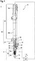
- Figure 1 shows a print head 10 in a perspective external view.
- the print head 10 has a housing 19 which has a funnel-shaped feed 12 for a starting material 21 in the form of granules 21.
- the housing 19 merges into an intermediate piece 38 at the top.
- This intermediate piece 38 comprises a cylinder 37 in which a piston 31 is guided.
- the piston 31 is in the in Figure 1 selected perspective covered by the cylinder 37 and therefore only indicated.
- the movement of the piston 31 is driven by an electric motor 32a, the rotary movement of which is translated into a linear movement by a mechanical spindle 32b.
- the piston 31 and the drive source 32 together form a conveying device 30 for conveying the granulate 21.
- the path s of the piston 31 is measured with a path measuring system 33.
- the force F with which the piston 31 presses on the granulate 21 is measured with a force sensor 34.
- the force F and the path s are fed to an active control 35, which also receives a setpoint Fs for the force F as input and controls the electric motor 32a to the effect that the actual force F is kept in accordance with the setpoint Fs.
- the measurement of the path s ensures compliance with the boundary condition that the piston 31 should only come into contact with the completely solid granulate 21 of the starting material 20, but not with an at least partially plasticized phase that sticks the piston 31.
- the housing 19 is formed by coolant 13, which includes active cooling 13a with a cooling medium and passive cooling 13b with cooling fins.
- the housing 16 is surrounded on its outer circumference by a heating band 15 which provides the heating energy for the plasticization of the starting material 21.
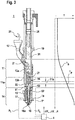
- FIG. 10 shows the interior of the printhead 10 at the portion of the duty cycle that is printing.
- the piston 31 conveys the granulate 21 from the feed zone 11 into the plasticizing zone 14, also known as the metering zone called because this is where the starting material 21 is measured in portions.
- the feed zone 11 adjoins the plasticization zone 14 via a compression zone 11a.
- Within the compression zone 11a there is the boundary layer 11b between highly compressed, but still firm and non-sticky granulate 21 on the one hand and material 22 that has started to liquefy on the other.
- the position shown is the front end of the piston 31 exactly in this boundary layer 11b.
- the interior of the housing 19 is designed as a straight circular cylinder in the upper region of the housing 19 up to and including the boundary layer 11b, in which the piston 31 can be guided. Further down, the interior merges into a melted geometry 51.
- This melting geometry 51 is distinguished, on the one hand, by the fact that its inner cross section tapers further and further downwards, so that the pressure of the liquid material 22 or the liquid phase 22 increases further and further.
- the inner wall of the melted geometry 51 has a structuring which effects a thorough mixing of the liquid phase 22 of the starting material 21. This structuring can be rib-shaped, for example, as shown in FIG Figure 2 is shown as an example.
- the heating band 15 is arranged on the outer circumference of the housing 19, the heating power of which is homogeneously distributed over the liquid phase 22 by a heat conducting structure 52 (heat conducting torpedo) arranged in the interior of the housing 19, i.e. within the liquid phase 22.
- a heat conducting structure 52 heat conducting torpedo
- Any other type of heating is also possible, as shown by the heating band 15 shown by way of example.
- the pressure p L of the liquid phase 22 is measured with a pressure sensor 17, and the temperature T L of the liquid phase 22 is measured with a temperature sensor 18.
- the area 16a is only a few cubic millimeters in size, so that no excess granulate 21 is melted.
- the heat conducting structure 52 ensures that the liquid phase 22 of the starting material 21 in the region 26a always has the highest possible viscosity without overheating.
- the measured values for p L and T L are forwarded to an evaluation unit 4, which also provides the temperature measured value T * a directly at the upper limit the plasticizing zone 14 arranged further temperature sensor 53 receives as input.
- a strand 23 is driven from the liquid phase 22 of the starting material 21 by the pressure p L generated by the piston 31 through the outlet opening 16 of the print head 10 and is deposited on an object 60 to be manufactured.
- the evaluation unit 4 calculates the amount ⁇ V + by which the volume of the strand 23 increases on the one hand due to the relaxation from the high pressure p L and by which amount ⁇ V - this volume decreases on the other hand due to the cooling from the high temperature T L.
- the energy input E into the object 60 by the deposited material 23 is also calculated.
- the piston 31 is guided in the housing 19 with a slight ventilation gap 54.
- the ambient air contained in the bed of granules 21, which is released when this bed is compressed, can be discharged through this gap 54.
- gases that arise during the plasticization or partial decomposition of the starting material 21 can also be discharged.
- the housing 19 is cooled between the boundary layer 11b and the feed 12 by coolant 13, which are formed from the active cooling 13a with a flowing cooling medium and from the passive cooling 13b by means of cooling fins.
- coolant 13 which are formed from the active cooling 13a with a flowing cooling medium and from the passive cooling 13b by means of cooling fins.
- the temperature profile along the longitudinal axis 10a of the print head 10 from cold (-) to warm (+) is drawn qualitatively to the right of the print head 10.
- FIG. 10 shows the same printhead 10 in the same view as in FIG Figure 2 with the difference that here the piston 31 has been withdrawn upwards behind the intake zone 11. On the one hand, this has the effect that the in Figure 3 In the state shown, no strand 23 of starting material 21 emerges from the outlet opening 16. On the other hand, the intake zone 11 is free for fresh granulate 21 to trickle down. When the piston 31 is lowered again, the fresh granulate 21, as in FIG Figure 2 shown, compressed and plasticized in the plasticizing zone 14 before it emerges as a strand 23 from the outlet opening 16.
- Figure 4 shows a first embodiment of the print head 10 according to the invention in a sectional drawing.
- the piston 31 has a first piston section 5, facing the plasticizing zone 14, with a guide surface 9 through which the piston 31 is guided in a bore 7 of the print head 10 or of the housing 19.
- the guide surface 9 is longer in its axial extent l 2 than a maximum axial extent l 1 of an opening surface 8 of the feed 12 to the bore 7.
- the opening surface 8 of the feed 12 to the bore 7 is designed so that the granules 21 fed optimally into the bore , or can be fed into the feed zone 11.
- the axial extension l 2 of the guide surface 9 of the piston 31 is 1.2 times the maximum axial extension l 1 of the opening surface 8 in this embodiment.
- the first piston section 5 has a piston diameter d 2 , the axial extent l 2 of the guide surface 9 of the piston 31 preferably being 1.25 times the piston diameter d 2 of the first piston section 5.
- the piston 31 shown with the correspondingly dimensioned guide surface 9 prevents the piston 31 from tilting in the bore 7 and reduces the penetration of the deformed granulate into the gap between the guide surface 9 and the bore 7.
- the piston 31 also has a second piston section 6, the piston diameter d 1 of which is smaller than the piston diameter d 2 of the first piston section 5.
- Figure 5 shows a second exemplary embodiment of the print head 10, the piston 31 having a recess 40 which is arranged between the first piston section and a third piston section 41.
- the third piston section 41 is arranged between the first 5 and the second 6 piston sections and it has the same piston diameter d 2 as the first piston section (5).
- the groove 40 is used to evaluate the quality of the print head settings by checking the groove 40 for deposits during the maintenance intervals.
- the axial extension l 2 of the guide surface 9 of the piston 31 is 1.2 times the maximum axial extension l 1 of the opening surface 8 and extends to the recess 40.
- the print head 10 can be integrated into any desired 3D printer.
Landscapes
- Engineering & Computer Science (AREA)
- Materials Engineering (AREA)
- Chemical & Material Sciences (AREA)
- Mechanical Engineering (AREA)
- Manufacturing & Machinery (AREA)
- Optics & Photonics (AREA)
- Physics & Mathematics (AREA)
- Health & Medical Sciences (AREA)
- Environmental & Geological Engineering (AREA)
- Toxicology (AREA)
- Clinical Laboratory Science (AREA)
- Processing And Handling Of Plastics And Other Materials For Molding In General (AREA)
- Ink Jet (AREA)
Claims (8)
- Tête d'impression (10) pour une imprimante 3D (1), comprenant une zone de chargement (11) dotée d'une alimentation (12) pour un matériau de départ (21) de viscosité variable, une zone de plastification (14) dotée d'un dispositif de chauffage (15) et d'une ouverture de sortie (16) pour la phase liquide (22) du matériau de départ (21), ainsi qu'un dispositif de transport (30) pour le transport du matériau de départ (21) depuis la zone de chargement (11) dans la zone de plastification (14), le dispositif de transport (30) comprenant un piston (31) qui peut être introduit dans la zone de chargement (11),le piston (31) comprenant une première section de piston (5) tournée vers la zone de plastification (14), dotée d'une surface de guidage (9) qui permet de guider le piston (31) dans un alésage (7) de la tête d'impression (10), caractérisée en ce que la surface de guidage (9) est plus longue dans son extension axiale (l2) qu'une extension axiale maximale (l1) d'une surface d'ouverture (8) de l'alimentation (12) vers l'alésage (7), etl'extension axiale (l2) de la surface de guidage (9) du piston (31) est d'entre 1 et 2,5 fois un diamètre de piston (d2) de la première section de piston (5).
- Tête d'impression (10) selon la revendication 1, caractérisée en ce que
l'extension axiale (l2) de la surface de guidage (9) du piston (31) est d'entre 1,1 et 1,3 fois l'extension axiale maximale (l1) de la surface d'ouverture (8). - Tête d'impression (10) selon l'une quelconque des revendications précédentes, caractérisée en ce que l'extension axiale (l2) de la surface de guidage (9) du piston (31) est de 1,2 fois l'extension axiale maximale (l1) de la surface d'ouverture (8).
- Tête d'impression (10) selon l'une quelconque des revendications précédentes, caractérisée en ce que l'extension axiale (l2) de la surface de guidage (9) du piston (31) est de 1,25 fois le diamètre de piston (d2) de la première section de piston (5).
- Tête d'impression (10) selon l'une quelconque des revendications précédentes, caractérisée en ce que le piston (31) comprend une deuxième section de piston (6), dont le diamètre de piston (d1) est inférieur au diamètre de piston (d2) de la première section de piston (5) .
- Tête d'impression (10) selon l'une quelconque des revendications précédentes, caractérisée en ce que le piston (31) comprend une entaille (40), qui est agencée entre la première section de piston (5) et une troisième section de piston (41).
- Tête d'impression (10) selon la revendication 6, caractérisée en ce que
la troisième section de piston (41) est agencée entre la première (5) et la deuxième (6) section de piston. - Tête d'impression (10) selon la revendication 7, caractérisée en ce que
la première section de piston (5) et la troisième section de piston (41) présentent le même diamètre de piston (d2).
Applications Claiming Priority (2)
| Application Number | Priority Date | Filing Date | Title |
|---|---|---|---|
| DE102017218707.7A DE102017218707A1 (de) | 2017-10-19 | 2017-10-19 | Druckkopf für einen 3D-Drucker |
| PCT/EP2018/078403 WO2019076982A1 (fr) | 2017-10-19 | 2018-10-17 | Tête d'impression pour imprimante 3d |
Publications (2)
| Publication Number | Publication Date |
|---|---|
| EP3697594A1 EP3697594A1 (fr) | 2020-08-26 |
| EP3697594B1 true EP3697594B1 (fr) | 2021-12-08 |
Family
ID=63915035
Family Applications (1)
| Application Number | Title | Priority Date | Filing Date |
|---|---|---|---|
| EP18789387.0A Active EP3697594B1 (fr) | 2017-10-19 | 2018-10-17 | Tête d'impression pour imprimante 3d |
Country Status (5)
| Country | Link |
|---|---|
| US (1) | US11584072B2 (fr) |
| EP (1) | EP3697594B1 (fr) |
| CN (1) | CN111225782B (fr) |
| DE (1) | DE102017218707A1 (fr) |
| WO (1) | WO2019076982A1 (fr) |
Families Citing this family (2)
| Publication number | Priority date | Publication date | Assignee | Title |
|---|---|---|---|---|
| DE102016222306A1 (de) * | 2016-11-14 | 2018-05-17 | Robert Bosch Gmbh | Besser kontrollierbarer Druckkopf für 3D-Drucker |
| GB2620611A (en) * | 2022-07-13 | 2024-01-17 | Kraft Foods Schweiz Holding Gmbh | A method and apparatus for forming a steady stream of plasticised solid feed material |
Family Cites Families (19)
| Publication number | Priority date | Publication date | Assignee | Title |
|---|---|---|---|---|
| DE3827772A1 (de) * | 1988-08-16 | 1990-02-22 | Thomas Paul Engel | Vorrichtung und verfahren zur formgebung von halbzeug aus hochmolekularen kunststoffen |
| DE4319128C1 (de) * | 1993-06-09 | 1995-02-23 | Fraunhofer Ges Forschung | Verfahren und Einrichtung zur freiformenden Herstellung dreidimensionaler Bauteile einer vorgegebenen Form |
| JPH10235701A (ja) * | 1997-02-27 | 1998-09-08 | Mitsubishi Heavy Ind Ltd | 射出成形機の射出装置 |
| US6067480A (en) * | 1997-04-02 | 2000-05-23 | Stratasys, Inc. | Method and apparatus for in-situ formation of three-dimensional solid objects by extrusion of polymeric materials |
| US6200127B1 (en) * | 1999-02-26 | 2001-03-13 | Milacron Inc. | Bi-directional check ring for a two-stage injection unit |
| DE102006035816B4 (de) * | 2006-08-01 | 2009-12-17 | Landshuter Werkzeugbau Alfred Steinl Gmbh & Co. Kg | Drossel für Spritzgießmaschine zum Spritzgießen von Kautschuk- bzw. Elastomermaterialien |
| US8323247B2 (en) * | 2009-05-08 | 2012-12-04 | The Alfred E. Mann Foundation For Scientific Research | Fluid transfer devices with fluid bypass and ambulatory infusion devices including same |
| KR101353564B1 (ko) | 2012-11-15 | 2014-01-22 | 한국생산기술연구원 | 혼합성능이 개선된 믹싱헤드 및 그 토출장치 |
| US9186846B1 (en) * | 2013-03-22 | 2015-11-17 | Markforged, Inc. | Methods for composite filament threading in three dimensional printing |
| US9579851B2 (en) * | 2013-03-22 | 2017-02-28 | Markforged, Inc. | Apparatus for fiber reinforced additive manufacturing |
| GB2516002A (en) | 2013-05-15 | 2015-01-14 | Rafael Zvi Karl Kilim | Plastic moulding method |
| KR102224271B1 (ko) * | 2014-01-31 | 2021-03-05 | 후루까와 로크 드릴 가부시끼가이샤 | 액압식 타격 장치 |
| JP2015168135A (ja) * | 2014-03-06 | 2015-09-28 | 三井化学株式会社 | 三次元物体の製造装置および三次元物体の製造方法 |
| US10279541B2 (en) * | 2015-06-26 | 2019-05-07 | The Boeing Company | Systems and methods for additive manufacturing processes |
| GB201519730D0 (en) | 2015-11-09 | 2015-12-23 | Univ Dublin | A method, system and device for three dimensional additive manufacturing in a liquid phase |
| DE102016222315A1 (de) * | 2016-11-14 | 2018-05-17 | Robert Bosch Gmbh | 3D-Druckkopf mit verbesserter Reproduzierbarkeit des Druckergebnisses |
| DE102016222306A1 (de) * | 2016-11-14 | 2018-05-17 | Robert Bosch Gmbh | Besser kontrollierbarer Druckkopf für 3D-Drucker |
| NL2018720B1 (en) * | 2017-04-14 | 2018-10-24 | Bond High Performance 3D Tech B V | Three-dimensional modeling method and system |
| WO2018200596A1 (fr) * | 2017-04-24 | 2018-11-01 | Desktop Metal, Inc. | Déplacement de matériau de construction à l'aide d'un dispositif de préhension dans un système d'impression en 3d |
-
2017
- 2017-10-19 DE DE102017218707.7A patent/DE102017218707A1/de active Pending
-
2018
- 2018-10-17 CN CN201880067777.6A patent/CN111225782B/zh active Active
- 2018-10-17 US US16/757,442 patent/US11584072B2/en active Active
- 2018-10-17 EP EP18789387.0A patent/EP3697594B1/fr active Active
- 2018-10-17 WO PCT/EP2018/078403 patent/WO2019076982A1/fr unknown
Also Published As
| Publication number | Publication date |
|---|---|
| DE102017218707A1 (de) | 2019-04-25 |
| CN111225782B (zh) | 2022-03-25 |
| EP3697594A1 (fr) | 2020-08-26 |
| US11584072B2 (en) | 2023-02-21 |
| US20210187842A1 (en) | 2021-06-24 |
| WO2019076982A1 (fr) | 2019-04-25 |
| CN111225782A (zh) | 2020-06-02 |
Similar Documents
| Publication | Publication Date | Title |
|---|---|---|
| EP3538366A1 (fr) | Tête d'impression de commande améliorée pour imprimante 3d | |
| DE102007051923B4 (de) | Vorrichtung und Verfahren zur Verarbeitung polymerer Werkstoffe | |
| AT523204B1 (de) | Formmaschine zum Schaumformen | |
| DE3835250C1 (fr) | ||
| EP3697594B1 (fr) | Tête d'impression pour imprimante 3d | |
| WO2018015092A1 (fr) | Extrudeuse pour une imprimante 3d présentant un débit variable de matière | |
| DD142681A5 (de) | Extrudieren von blasfolien aus kunststoff,insbesondere steifem polyvinylchlorid | |
| DE102006001171A1 (de) | Extruder mit Materialeintrag durch Gehäuse und Entgasung | |
| DE1554756B2 (de) | Schneckenstrangpresse zur verarbeitung thermoplastischer werkstoffe | |
| EP0846050B1 (fr) | Presse de moulage par injection avec systeme a canal chauffant integre | |
| EP1884341A2 (fr) | Dispositif destiné à la fabrication de produits en forme de cordon | |
| DE2059496C3 (de) | Vorrichtung zum Plastifizieren von Kunststoffen | |
| EP3524402B1 (fr) | Buse de fermeture à aiguille actionnée pourvue de canal d'aiguille séparé et de canal de fusion | |
| WO2019109114A1 (fr) | Tête d'impression pour l'application couche par couche de matériau | |
| DE3917678C2 (fr) | ||
| DE19904227A1 (de) | Schneckenmaschine und Verfahren zum Recycling von Thermoplast-Schaum-Materialien | |
| EP4045248A1 (fr) | Pièce de mélange pour une unité de plastification d'une machine d'injection à vis | |
| DE19801412C2 (de) | Plastifizier- und Einspritzeinheit für eine Spritzgießmaschine | |
| EP0663277B1 (fr) | Appareil de soudage par extrusion pour matières thermoplastiques | |
| EP3569384A1 (fr) | Procédé d'extrusion de matière plastique renforcée par des fibres | |
| EP3554797A1 (fr) | Tête d'impression pour l'application couche par couche de matériau | |
| AT524541B1 (de) | Vorrichtung zum Entgasen und Verfahren zum Entgasen einer plastifizierten Masse | |
| AT525647B1 (de) | Plastifizieraggregat | |
| DE4238277C2 (de) | Mehrzonenschnecke | |
| DE69722920T2 (de) | Verfahren und vorrichtung zum formen von kunststoff |
Legal Events
| Date | Code | Title | Description |
|---|---|---|---|
| STAA | Information on the status of an ep patent application or granted ep patent |
Free format text: STATUS: UNKNOWN |
|
| STAA | Information on the status of an ep patent application or granted ep patent |
Free format text: STATUS: THE INTERNATIONAL PUBLICATION HAS BEEN MADE |
|
| PUAI | Public reference made under article 153(3) epc to a published international application that has entered the european phase |
Free format text: ORIGINAL CODE: 0009012 |
|
| STAA | Information on the status of an ep patent application or granted ep patent |
Free format text: STATUS: REQUEST FOR EXAMINATION WAS MADE |
|
| 17P | Request for examination filed |
Effective date: 20200519 |
|
| AK | Designated contracting states |
Kind code of ref document: A1 Designated state(s): AL AT BE BG CH CY CZ DE DK EE ES FI FR GB GR HR HU IE IS IT LI LT LU LV MC MK MT NL NO PL PT RO RS SE SI SK SM TR |
|
| AX | Request for extension of the european patent |
Extension state: BA ME |
|
| DAV | Request for validation of the european patent (deleted) | ||
| DAX | Request for extension of the european patent (deleted) | ||
| GRAP | Despatch of communication of intention to grant a patent |
Free format text: ORIGINAL CODE: EPIDOSNIGR1 |
|
| STAA | Information on the status of an ep patent application or granted ep patent |
Free format text: STATUS: GRANT OF PATENT IS INTENDED |
|
| RIC1 | Information provided on ipc code assigned before grant |
Ipc: B29C 64/106 20170101AFI20210527BHEP Ipc: B29C 64/209 20170101ALI20210527BHEP Ipc: B33Y 30/00 20150101ALI20210527BHEP Ipc: B29C 48/02 20190101ALI20210527BHEP Ipc: B29C 48/25 20190101ALI20210527BHEP Ipc: B29C 48/92 20190101ALI20210527BHEP Ipc: B29C 48/05 20190101ALN20210527BHEP |
|
| INTG | Intention to grant announced |
Effective date: 20210611 |
|
| GRAS | Grant fee paid |
Free format text: ORIGINAL CODE: EPIDOSNIGR3 |
|
| GRAA | (expected) grant |
Free format text: ORIGINAL CODE: 0009210 |
|
| STAA | Information on the status of an ep patent application or granted ep patent |
Free format text: STATUS: THE PATENT HAS BEEN GRANTED |
|
| AK | Designated contracting states |
Kind code of ref document: B1 Designated state(s): AL AT BE BG CH CY CZ DE DK EE ES FI FR GB GR HR HU IE IS IT LI LT LU LV MC MK MT NL NO PL PT RO RS SE SI SK SM TR |
|
| REG | Reference to a national code |
Ref country code: GB Ref legal event code: FG4D Free format text: NOT ENGLISH |
|
| REG | Reference to a national code |
Ref country code: AT Ref legal event code: REF Ref document number: 1453430 Country of ref document: AT Kind code of ref document: T Effective date: 20211215 Ref country code: CH Ref legal event code: EP |
|
| REG | Reference to a national code |
Ref country code: DE Ref legal event code: R096 Ref document number: 502018008166 Country of ref document: DE |
|
| REG | Reference to a national code |
Ref country code: IE Ref legal event code: FG4D Free format text: LANGUAGE OF EP DOCUMENT: GERMAN |
|
| REG | Reference to a national code |
Ref country code: LT Ref legal event code: MG9D |
|
| REG | Reference to a national code |
Ref country code: NL Ref legal event code: MP Effective date: 20211208 |
|
| PG25 | Lapsed in a contracting state [announced via postgrant information from national office to epo] |
Ref country code: RS Free format text: LAPSE BECAUSE OF FAILURE TO SUBMIT A TRANSLATION OF THE DESCRIPTION OR TO PAY THE FEE WITHIN THE PRESCRIBED TIME-LIMIT Effective date: 20211208 Ref country code: LT Free format text: LAPSE BECAUSE OF FAILURE TO SUBMIT A TRANSLATION OF THE DESCRIPTION OR TO PAY THE FEE WITHIN THE PRESCRIBED TIME-LIMIT Effective date: 20211208 Ref country code: FI Free format text: LAPSE BECAUSE OF FAILURE TO SUBMIT A TRANSLATION OF THE DESCRIPTION OR TO PAY THE FEE WITHIN THE PRESCRIBED TIME-LIMIT Effective date: 20211208 Ref country code: BG Free format text: LAPSE BECAUSE OF FAILURE TO SUBMIT A TRANSLATION OF THE DESCRIPTION OR TO PAY THE FEE WITHIN THE PRESCRIBED TIME-LIMIT Effective date: 20220308 |
|
| PG25 | Lapsed in a contracting state [announced via postgrant information from national office to epo] |
Ref country code: SE Free format text: LAPSE BECAUSE OF FAILURE TO SUBMIT A TRANSLATION OF THE DESCRIPTION OR TO PAY THE FEE WITHIN THE PRESCRIBED TIME-LIMIT Effective date: 20211208 Ref country code: NO Free format text: LAPSE BECAUSE OF FAILURE TO SUBMIT A TRANSLATION OF THE DESCRIPTION OR TO PAY THE FEE WITHIN THE PRESCRIBED TIME-LIMIT Effective date: 20220308 Ref country code: LV Free format text: LAPSE BECAUSE OF FAILURE TO SUBMIT A TRANSLATION OF THE DESCRIPTION OR TO PAY THE FEE WITHIN THE PRESCRIBED TIME-LIMIT Effective date: 20211208 Ref country code: HR Free format text: LAPSE BECAUSE OF FAILURE TO SUBMIT A TRANSLATION OF THE DESCRIPTION OR TO PAY THE FEE WITHIN THE PRESCRIBED TIME-LIMIT Effective date: 20211208 Ref country code: GR Free format text: LAPSE BECAUSE OF FAILURE TO SUBMIT A TRANSLATION OF THE DESCRIPTION OR TO PAY THE FEE WITHIN THE PRESCRIBED TIME-LIMIT Effective date: 20220309 |
|
| PG25 | Lapsed in a contracting state [announced via postgrant information from national office to epo] |
Ref country code: NL Free format text: LAPSE BECAUSE OF FAILURE TO SUBMIT A TRANSLATION OF THE DESCRIPTION OR TO PAY THE FEE WITHIN THE PRESCRIBED TIME-LIMIT Effective date: 20211208 |
|
| PG25 | Lapsed in a contracting state [announced via postgrant information from national office to epo] |
Ref country code: SM Free format text: LAPSE BECAUSE OF FAILURE TO SUBMIT A TRANSLATION OF THE DESCRIPTION OR TO PAY THE FEE WITHIN THE PRESCRIBED TIME-LIMIT Effective date: 20211208 Ref country code: SK Free format text: LAPSE BECAUSE OF FAILURE TO SUBMIT A TRANSLATION OF THE DESCRIPTION OR TO PAY THE FEE WITHIN THE PRESCRIBED TIME-LIMIT Effective date: 20211208 Ref country code: RO Free format text: LAPSE BECAUSE OF FAILURE TO SUBMIT A TRANSLATION OF THE DESCRIPTION OR TO PAY THE FEE WITHIN THE PRESCRIBED TIME-LIMIT Effective date: 20211208 Ref country code: PT Free format text: LAPSE BECAUSE OF FAILURE TO SUBMIT A TRANSLATION OF THE DESCRIPTION OR TO PAY THE FEE WITHIN THE PRESCRIBED TIME-LIMIT Effective date: 20220408 Ref country code: ES Free format text: LAPSE BECAUSE OF FAILURE TO SUBMIT A TRANSLATION OF THE DESCRIPTION OR TO PAY THE FEE WITHIN THE PRESCRIBED TIME-LIMIT Effective date: 20211208 Ref country code: EE Free format text: LAPSE BECAUSE OF FAILURE TO SUBMIT A TRANSLATION OF THE DESCRIPTION OR TO PAY THE FEE WITHIN THE PRESCRIBED TIME-LIMIT Effective date: 20211208 Ref country code: CZ Free format text: LAPSE BECAUSE OF FAILURE TO SUBMIT A TRANSLATION OF THE DESCRIPTION OR TO PAY THE FEE WITHIN THE PRESCRIBED TIME-LIMIT Effective date: 20211208 |
|
| PG25 | Lapsed in a contracting state [announced via postgrant information from national office to epo] |
Ref country code: PL Free format text: LAPSE BECAUSE OF FAILURE TO SUBMIT A TRANSLATION OF THE DESCRIPTION OR TO PAY THE FEE WITHIN THE PRESCRIBED TIME-LIMIT Effective date: 20211208 |
|
| REG | Reference to a national code |
Ref country code: DE Ref legal event code: R097 Ref document number: 502018008166 Country of ref document: DE |
|
| PG25 | Lapsed in a contracting state [announced via postgrant information from national office to epo] |
Ref country code: IS Free format text: LAPSE BECAUSE OF FAILURE TO SUBMIT A TRANSLATION OF THE DESCRIPTION OR TO PAY THE FEE WITHIN THE PRESCRIBED TIME-LIMIT Effective date: 20220408 |
|
| PLBE | No opposition filed within time limit |
Free format text: ORIGINAL CODE: 0009261 |
|
| STAA | Information on the status of an ep patent application or granted ep patent |
Free format text: STATUS: NO OPPOSITION FILED WITHIN TIME LIMIT |
|
| PG25 | Lapsed in a contracting state [announced via postgrant information from national office to epo] |
Ref country code: DK Free format text: LAPSE BECAUSE OF FAILURE TO SUBMIT A TRANSLATION OF THE DESCRIPTION OR TO PAY THE FEE WITHIN THE PRESCRIBED TIME-LIMIT Effective date: 20211208 Ref country code: AL Free format text: LAPSE BECAUSE OF FAILURE TO SUBMIT A TRANSLATION OF THE DESCRIPTION OR TO PAY THE FEE WITHIN THE PRESCRIBED TIME-LIMIT Effective date: 20211208 |
|
| 26N | No opposition filed |
Effective date: 20220909 |
|
| PG25 | Lapsed in a contracting state [announced via postgrant information from national office to epo] |
Ref country code: SI Free format text: LAPSE BECAUSE OF FAILURE TO SUBMIT A TRANSLATION OF THE DESCRIPTION OR TO PAY THE FEE WITHIN THE PRESCRIBED TIME-LIMIT Effective date: 20211208 |
|
| PG25 | Lapsed in a contracting state [announced via postgrant information from national office to epo] |
Ref country code: MC Free format text: LAPSE BECAUSE OF FAILURE TO SUBMIT A TRANSLATION OF THE DESCRIPTION OR TO PAY THE FEE WITHIN THE PRESCRIBED TIME-LIMIT Effective date: 20211208 |
|
| REG | Reference to a national code |
Ref country code: CH Ref legal event code: PL |
|
| P01 | Opt-out of the competence of the unified patent court (upc) registered |
Effective date: 20230509 |
|
| REG | Reference to a national code |
Ref country code: BE Ref legal event code: MM Effective date: 20221031 |
|
| PG25 | Lapsed in a contracting state [announced via postgrant information from national office to epo] |
Ref country code: LU Free format text: LAPSE BECAUSE OF NON-PAYMENT OF DUE FEES Effective date: 20221017 |
|
| PG25 | Lapsed in a contracting state [announced via postgrant information from national office to epo] |
Ref country code: LI Free format text: LAPSE BECAUSE OF NON-PAYMENT OF DUE FEES Effective date: 20221031 Ref country code: CH Free format text: LAPSE BECAUSE OF NON-PAYMENT OF DUE FEES Effective date: 20221031 |
|
| PG25 | Lapsed in a contracting state [announced via postgrant information from national office to epo] |
Ref country code: BE Free format text: LAPSE BECAUSE OF NON-PAYMENT OF DUE FEES Effective date: 20221031 |
|
| PG25 | Lapsed in a contracting state [announced via postgrant information from national office to epo] |
Ref country code: IE Free format text: LAPSE BECAUSE OF NON-PAYMENT OF DUE FEES Effective date: 20221017 |
|
| PGFP | Annual fee paid to national office [announced via postgrant information from national office to epo] |
Ref country code: GB Payment date: 20231025 Year of fee payment: 6 |
|
| PGFP | Annual fee paid to national office [announced via postgrant information from national office to epo] |
Ref country code: IT Payment date: 20231031 Year of fee payment: 6 Ref country code: FR Payment date: 20231023 Year of fee payment: 6 |
|
| PG25 | Lapsed in a contracting state [announced via postgrant information from national office to epo] |
Ref country code: CY Free format text: LAPSE BECAUSE OF FAILURE TO SUBMIT A TRANSLATION OF THE DESCRIPTION OR TO PAY THE FEE WITHIN THE PRESCRIBED TIME-LIMIT Effective date: 20211208 |
|
| PGFP | Annual fee paid to national office [announced via postgrant information from national office to epo] |
Ref country code: DE Payment date: 20231218 Year of fee payment: 6 |