EP1884341A2 - Dispositif destiné à la fabrication de produits en forme de cordon - Google Patents
Dispositif destiné à la fabrication de produits en forme de cordon Download PDFInfo
- Publication number
- EP1884341A2 EP1884341A2 EP07013446A EP07013446A EP1884341A2 EP 1884341 A2 EP1884341 A2 EP 1884341A2 EP 07013446 A EP07013446 A EP 07013446A EP 07013446 A EP07013446 A EP 07013446A EP 1884341 A2 EP1884341 A2 EP 1884341A2
- Authority
- EP
- European Patent Office
- Prior art keywords
- outer cylinder
- extruder
- piston
- volume
- raw material
- Prior art date
- Legal status (The legal status is an assumption and is not a legal conclusion. Google has not performed a legal analysis and makes no representation as to the accuracy of the status listed.)
- Withdrawn
Links
- 238000000034 method Methods 0.000 title claims description 12
- 238000004519 manufacturing process Methods 0.000 title claims description 9
- 238000010438 heat treatment Methods 0.000 claims abstract description 16
- 229920000642 polymer Polymers 0.000 claims abstract description 16
- 238000001125 extrusion Methods 0.000 claims abstract description 9
- 238000002156 mixing Methods 0.000 claims abstract description 6
- 239000000463 material Substances 0.000 claims description 29
- 239000007921 spray Substances 0.000 claims description 17
- 239000000155 melt Substances 0.000 claims description 14
- 238000011049 filling Methods 0.000 claims description 11
- 230000008569 process Effects 0.000 claims description 11
- 239000002994 raw material Substances 0.000 claims description 7
- 229920001169 thermoplastic Polymers 0.000 claims description 3
- 230000000694 effects Effects 0.000 claims description 2
- 239000004416 thermosoftening plastic Substances 0.000 claims description 2
- 238000002844 melting Methods 0.000 claims 2
- 230000008018 melting Effects 0.000 claims 2
- 238000005086 pumping Methods 0.000 claims 1
- 239000012943 hotmelt Substances 0.000 abstract description 2
- 229920003023 plastic Polymers 0.000 abstract 2
- 239000004033 plastic Substances 0.000 abstract 2
- 239000008187 granular material Substances 0.000 description 5
- 238000007493 shaping process Methods 0.000 description 4
- 238000010276 construction Methods 0.000 description 3
- 238000009826 distribution Methods 0.000 description 2
- 230000007246 mechanism Effects 0.000 description 2
- 239000000203 mixture Substances 0.000 description 2
- 238000000465 moulding Methods 0.000 description 2
- 239000000843 powder Substances 0.000 description 2
- 238000005299 abrasion Methods 0.000 description 1
- 230000008859 change Effects 0.000 description 1
- 238000004140 cleaning Methods 0.000 description 1
- 239000011248 coating agent Substances 0.000 description 1
- 238000000576 coating method Methods 0.000 description 1
- 230000006835 compression Effects 0.000 description 1
- 238000007906 compression Methods 0.000 description 1
- 238000001816 cooling Methods 0.000 description 1
- 238000005520 cutting process Methods 0.000 description 1
- 230000001419 dependent effect Effects 0.000 description 1
- 238000001514 detection method Methods 0.000 description 1
- 238000010586 diagram Methods 0.000 description 1
- 238000006073 displacement reaction Methods 0.000 description 1
- 239000000806 elastomer Substances 0.000 description 1
- 238000005516 engineering process Methods 0.000 description 1
- 229920000295 expanded polytetrafluoroethylene Polymers 0.000 description 1
- 238000000605 extraction Methods 0.000 description 1
- 239000003292 glue Substances 0.000 description 1
- 238000010409 ironing Methods 0.000 description 1
- 238000012423 maintenance Methods 0.000 description 1
- 239000000289 melt material Substances 0.000 description 1
- 238000004806 packaging method and process Methods 0.000 description 1
- 230000035515 penetration Effects 0.000 description 1
- 239000002861 polymer material Substances 0.000 description 1
- 229920001343 polytetrafluoroethylene Polymers 0.000 description 1
- 239000004810 polytetrafluoroethylene Substances 0.000 description 1
- 238000003825 pressing Methods 0.000 description 1
- 238000000275 quality assurance Methods 0.000 description 1
- 238000007789 sealing Methods 0.000 description 1
- 239000007787 solid Substances 0.000 description 1
- 125000006850 spacer group Chemical group 0.000 description 1
- 230000003068 static effect Effects 0.000 description 1
- 229920002725 thermoplastic elastomer Polymers 0.000 description 1
- XOUPWBJVJFQSLK-UHFFFAOYSA-J titanium(4+);tetranitrite Chemical compound [Ti+4].[O-]N=O.[O-]N=O.[O-]N=O.[O-]N=O XOUPWBJVJFQSLK-UHFFFAOYSA-J 0.000 description 1
- 230000007704 transition Effects 0.000 description 1
Images


Classifications
-
- B—PERFORMING OPERATIONS; TRANSPORTING
- B29—WORKING OF PLASTICS; WORKING OF SUBSTANCES IN A PLASTIC STATE IN GENERAL
- B29C—SHAPING OR JOINING OF PLASTICS; SHAPING OF MATERIAL IN A PLASTIC STATE, NOT OTHERWISE PROVIDED FOR; AFTER-TREATMENT OF THE SHAPED PRODUCTS, e.g. REPAIRING
- B29C48/00—Extrusion moulding, i.e. expressing the moulding material through a die or nozzle which imparts the desired form; Apparatus therefor
- B29C48/25—Component parts, details or accessories; Auxiliary operations
- B29C48/36—Means for plasticising or homogenising the moulding material or forcing it through the nozzle or die
- B29C48/475—Means for plasticising or homogenising the moulding material or forcing it through the nozzle or die using pistons, accumulators or press rams
-
- B—PERFORMING OPERATIONS; TRANSPORTING
- B29—WORKING OF PLASTICS; WORKING OF SUBSTANCES IN A PLASTIC STATE IN GENERAL
- B29C—SHAPING OR JOINING OF PLASTICS; SHAPING OF MATERIAL IN A PLASTIC STATE, NOT OTHERWISE PROVIDED FOR; AFTER-TREATMENT OF THE SHAPED PRODUCTS, e.g. REPAIRING
- B29C48/00—Extrusion moulding, i.e. expressing the moulding material through a die or nozzle which imparts the desired form; Apparatus therefor
- B29C48/03—Extrusion moulding, i.e. expressing the moulding material through a die or nozzle which imparts the desired form; Apparatus therefor characterised by the shape of the extruded material at extrusion
- B29C48/05—Filamentary, e.g. strands
-
- B—PERFORMING OPERATIONS; TRANSPORTING
- B29—WORKING OF PLASTICS; WORKING OF SUBSTANCES IN A PLASTIC STATE IN GENERAL
- B29C—SHAPING OR JOINING OF PLASTICS; SHAPING OF MATERIAL IN A PLASTIC STATE, NOT OTHERWISE PROVIDED FOR; AFTER-TREATMENT OF THE SHAPED PRODUCTS, e.g. REPAIRING
- B29C48/00—Extrusion moulding, i.e. expressing the moulding material through a die or nozzle which imparts the desired form; Apparatus therefor
- B29C48/25—Component parts, details or accessories; Auxiliary operations
- B29C48/36—Means for plasticising or homogenising the moulding material or forcing it through the nozzle or die
- B29C48/362—Means for plasticising or homogenising the moulding material or forcing it through the nozzle or die using static mixing devices
-
- B—PERFORMING OPERATIONS; TRANSPORTING
- B29—WORKING OF PLASTICS; WORKING OF SUBSTANCES IN A PLASTIC STATE IN GENERAL
- B29C—SHAPING OR JOINING OF PLASTICS; SHAPING OF MATERIAL IN A PLASTIC STATE, NOT OTHERWISE PROVIDED FOR; AFTER-TREATMENT OF THE SHAPED PRODUCTS, e.g. REPAIRING
- B29C48/00—Extrusion moulding, i.e. expressing the moulding material through a die or nozzle which imparts the desired form; Apparatus therefor
- B29C48/25—Component parts, details or accessories; Auxiliary operations
- B29C48/36—Means for plasticising or homogenising the moulding material or forcing it through the nozzle or die
- B29C48/395—Means for plasticising or homogenising the moulding material or forcing it through the nozzle or die using screws surrounded by a cooperating barrel, e.g. single screw extruders
- B29C48/397—Means for plasticising or homogenising the moulding material or forcing it through the nozzle or die using screws surrounded by a cooperating barrel, e.g. single screw extruders using a single screw
-
- B—PERFORMING OPERATIONS; TRANSPORTING
- B29—WORKING OF PLASTICS; WORKING OF SUBSTANCES IN A PLASTIC STATE IN GENERAL
- B29C—SHAPING OR JOINING OF PLASTICS; SHAPING OF MATERIAL IN A PLASTIC STATE, NOT OTHERWISE PROVIDED FOR; AFTER-TREATMENT OF THE SHAPED PRODUCTS, e.g. REPAIRING
- B29C48/00—Extrusion moulding, i.e. expressing the moulding material through a die or nozzle which imparts the desired form; Apparatus therefor
- B29C48/25—Component parts, details or accessories; Auxiliary operations
- B29C48/92—Measuring, controlling or regulating
-
- B—PERFORMING OPERATIONS; TRANSPORTING
- B29—WORKING OF PLASTICS; WORKING OF SUBSTANCES IN A PLASTIC STATE IN GENERAL
- B29C—SHAPING OR JOINING OF PLASTICS; SHAPING OF MATERIAL IN A PLASTIC STATE, NOT OTHERWISE PROVIDED FOR; AFTER-TREATMENT OF THE SHAPED PRODUCTS, e.g. REPAIRING
- B29C2948/00—Indexing scheme relating to extrusion moulding
- B29C2948/92—Measuring, controlling or regulating
- B29C2948/92009—Measured parameter
- B29C2948/92019—Pressure
-
- B—PERFORMING OPERATIONS; TRANSPORTING
- B29—WORKING OF PLASTICS; WORKING OF SUBSTANCES IN A PLASTIC STATE IN GENERAL
- B29C—SHAPING OR JOINING OF PLASTICS; SHAPING OF MATERIAL IN A PLASTIC STATE, NOT OTHERWISE PROVIDED FOR; AFTER-TREATMENT OF THE SHAPED PRODUCTS, e.g. REPAIRING
- B29C2948/00—Indexing scheme relating to extrusion moulding
- B29C2948/92—Measuring, controlling or regulating
- B29C2948/92323—Location or phase of measurement
- B29C2948/92361—Extrusion unit
- B29C2948/92409—Die; Nozzle zone
-
- B—PERFORMING OPERATIONS; TRANSPORTING
- B29—WORKING OF PLASTICS; WORKING OF SUBSTANCES IN A PLASTIC STATE IN GENERAL
- B29C—SHAPING OR JOINING OF PLASTICS; SHAPING OF MATERIAL IN A PLASTIC STATE, NOT OTHERWISE PROVIDED FOR; AFTER-TREATMENT OF THE SHAPED PRODUCTS, e.g. REPAIRING
- B29C2948/00—Indexing scheme relating to extrusion moulding
- B29C2948/92—Measuring, controlling or regulating
- B29C2948/92323—Location or phase of measurement
- B29C2948/92447—Moulded article
-
- B—PERFORMING OPERATIONS; TRANSPORTING
- B29—WORKING OF PLASTICS; WORKING OF SUBSTANCES IN A PLASTIC STATE IN GENERAL
- B29C—SHAPING OR JOINING OF PLASTICS; SHAPING OF MATERIAL IN A PLASTIC STATE, NOT OTHERWISE PROVIDED FOR; AFTER-TREATMENT OF THE SHAPED PRODUCTS, e.g. REPAIRING
- B29C2948/00—Indexing scheme relating to extrusion moulding
- B29C2948/92—Measuring, controlling or regulating
- B29C2948/92504—Controlled parameter
- B29C2948/92514—Pressure
-
- B—PERFORMING OPERATIONS; TRANSPORTING
- B29—WORKING OF PLASTICS; WORKING OF SUBSTANCES IN A PLASTIC STATE IN GENERAL
- B29C—SHAPING OR JOINING OF PLASTICS; SHAPING OF MATERIAL IN A PLASTIC STATE, NOT OTHERWISE PROVIDED FOR; AFTER-TREATMENT OF THE SHAPED PRODUCTS, e.g. REPAIRING
- B29C2948/00—Indexing scheme relating to extrusion moulding
- B29C2948/92—Measuring, controlling or regulating
- B29C2948/92819—Location or phase of control
- B29C2948/92857—Extrusion unit
- B29C2948/92904—Die; Nozzle zone
-
- B—PERFORMING OPERATIONS; TRANSPORTING
- B29—WORKING OF PLASTICS; WORKING OF SUBSTANCES IN A PLASTIC STATE IN GENERAL
- B29C—SHAPING OR JOINING OF PLASTICS; SHAPING OF MATERIAL IN A PLASTIC STATE, NOT OTHERWISE PROVIDED FOR; AFTER-TREATMENT OF THE SHAPED PRODUCTS, e.g. REPAIRING
- B29C2948/00—Indexing scheme relating to extrusion moulding
- B29C2948/92—Measuring, controlling or regulating
- B29C2948/92819—Location or phase of control
- B29C2948/92942—Moulded article
-
- B—PERFORMING OPERATIONS; TRANSPORTING
- B29—WORKING OF PLASTICS; WORKING OF SUBSTANCES IN A PLASTIC STATE IN GENERAL
- B29C—SHAPING OR JOINING OF PLASTICS; SHAPING OF MATERIAL IN A PLASTIC STATE, NOT OTHERWISE PROVIDED FOR; AFTER-TREATMENT OF THE SHAPED PRODUCTS, e.g. REPAIRING
- B29C48/00—Extrusion moulding, i.e. expressing the moulding material through a die or nozzle which imparts the desired form; Apparatus therefor
- B29C48/03—Extrusion moulding, i.e. expressing the moulding material through a die or nozzle which imparts the desired form; Apparatus therefor characterised by the shape of the extruded material at extrusion
- B29C48/09—Articles with cross-sections having partially or fully enclosed cavities, e.g. pipes or channels
Definitions
- the invention relates to devices for producing stranded goods made of polymeric materials.
- strand-shaped goods are extrudates of any desired length, which can be wound or stretched in the form of a hollow or solid profile with a high-precision cross-sectional geometry.
- Typical products according to this definition are thin-walled insulated electrical wires, thin-walled single or multi-lumen micro hoses, full round cords, but also any other conceivable miniaturized profiles, e.g. for sealing purposes in device construction, for assembly and packaging as spacers and much more.
- the invention relates to devices for the production of high-precision, thin-walled, polymeric micro-hoses and micro-profiles, which are suitable for use in the medical field.
- FIGs 1 and 2 show two embodiments of known extruder types with attached conventional forming tool (11).
- a conventional extruder 10 consists of a heatable cylindrical receptacle into which polymer material, for example granules, is introduced via the funnel intake. By heating, the material is then melted and fed via a screw propulsion (single-screw extruder) or a piston (paste, piston or RAM extruder) via a spray head (11) flanged to the extruder outlet for shaping the viscous polymer composition.
- the invention is based on this document as the closest prior art.
- the object of the invention is to provide an alternative device for the production of any strand-shaped goods, which ensures a high precision of the extrudates with simultaneous ease of use of the process.
- a paste extruder with a specially designed internal volume is proposed according to the invention, which is defined by a cylindrical inner mandrel and an outer cylinder shell, preferably with a circular cross-section.
- the internal volume is filled with the polymeric material (e.g., PE, PA, TPU, or other suitable thermoplastic polymers and elastomers).
- the polymeric raw material may be present, for example, as a powder or granules. Basically, however, other cross-sectional shapes for the design of the inner volume such. an ellipse or a regular or non-regular N-corner with N ⁇ 3 conceivable.
- the apparatus may be used to make tubular (or otherwise shaped) material candles from this powder or granules. Such candles ensure a faster and more efficient handling of the polymeric material in the extrusion of the strand-like material.
- a vacuum flange is provided for the outer cylinder, via which the air in the filling volume can be pumped off by means of oil-free pump after filling with polymer raw material.
- the polymer composition By heating, the polymer composition is melted and then via a hydraulic, electric or pneumatic drive unit, the melted material is squeezed out by means of a Ausschiebekolbens.
- the piston travel is detected by means of corresponding displacement transducers.
- a - preferably also heated - mixing section is provided, in which by special shaping a penetration of the melt flow in the sense a static mixing part takes place and so a uniform mixing of the melted material is achieved.
- micro hoses Since the amounts of material for micro hoses are very small, the free volumes of the melt channel and in the spray head are minimized as far as possible (micro-spray head). Thus, possible rheological flow anomalies such as e.g. Compression or "slip-stick” effects are reduced so that the melt from the ironing zone of the hose tool can emerge virtually pulsation-free and thus only the strand expansion as a function of the melt pressure and the withdrawal speed must be considered for the resulting geometry of the extrudate.
- possible rheological flow anomalies such as e.g. Compression or "slip-stick” effects are reduced so that the melt from the ironing zone of the hose tool can emerge virtually pulsation-free and thus only the strand expansion as a function of the melt pressure and the withdrawal speed must be considered for the resulting geometry of the extrudate.
- Downstream is a conventional cooling, calibration and extraction unit including cutting device, which are adapted in their dimensions to the small extrudate diameter.
- Figures 1 and 2 show for comparison known extruder (10) conventional design with screw or piston mechanism, flanged molding part (11) and with appropriately designed heating elements for a multi-stage zone heating of the process volume.
- Figure 3 shows schematically an embodiment of the extruder according to the invention with open outer cylinder (1), cylindrical inner mandrel (2), tubular Ausschiebekolben (3) and micro-cross spray head (4). These components are matched in their dimensions and filling volumes.
- the materials of the outer cylinder (1), inner mandrel (2) and Ausschiebekolben (3) are preferably selected for optimum mechanical stability with respect to sliding behavior and abrasion resistance.
- the surfaces of the extruder elements for example, have a special wear or adhesion-reducing coating, for example made of titanium nitrite.
- the extruder can be used together with any conventional longitudinal or transverse spray heads, preferably with very short and volume-reduced flow paths (micro-spray head), and with appropriately designed shaping tools.
- any conventional longitudinal or transverse spray heads preferably with very short and volume-reduced flow paths (micro-spray head), and with appropriately designed shaping tools.
- FIG. 4 shows the inner mandrel (2).
- several heating elements e.g. Hoch antiquesterrorismpatronen, positively secured (not shown).
- the heating elements of the inner mandrel can be controlled individually.
- Thermosensors are also installed inside the inner mandrel to record the current temperature distribution. By means of appropriate control of the distributed heating elements, an optimally homogeneous heat distribution can thus be set and maintained.
- the inner mandrel in the outlet region has a conical taper (5)
- the associated outer cylinder (1) has as its counterpart a corresponding tapered shape (8) in this region according to FIG.
- additional surface structures (6) can be introduced, which ensure a uniform mixing of the melt during the outflow.
- the surface structures (6) are designed diamond-shaped.
- Figure 5 shows the inner mandrel in plan view with typical dimensions in millimeters as a possible embodiment.
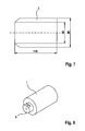
- the tubular Ausschiebekolben (3) is shown in perspective.
- the inner diameter of the Ausschiebekolbens (3) is tuned to the cross section of the inner mandrel, so that in the heated state a possible resistance-free sliding while ensuring the least possible gap is guaranteed.
- the conically tapering front (7) of the Ausschiebekolbens (3) is adapted to the shape of the inner mandrel (2) and the outer cylinder (1) in the outlet and thus ensures a minimum residual volume after the Auspressvorgang.
- Figure 7 shows the preferred possible dimensioning of the tubular Ausschiebekolbens (3) according to the dimensions of the inner mandrel (2) of Figure 5.
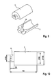
- FIG. 8 shows a perspective view of the outer cylinder (1)
- FIG. 9 shows a half-shell representation to illustrate the shape of the inner region.
- the inner outlet area (8) is tapered and adapted to the shape of the inner mandrel (2).
- the outlet flange (9) is the connection point for the melt pressure and melt temperature sensor, as well as for the micro-spray head (4) (see Fig. 3).
- a (heated) bypass not shown.
- the dimensions for the outer cylinder (1) of this embodiment are preferably shown in FIG. 10.
- the extruder for example, for cleaning, can be easily disassembled by internal mandrel (2) and Ausschiebekolben (3) can be pulled out of the Au- ⁇ enzylinder (1).
- outer cylinder (1) and inner mandrel (2) removed from the spray head (4) and the gap newly filled with granules while parallel a second pair of outer cylinder / inner mandrel (12) on the spray head ( 4) is attached and by Ausschiebekolben (3) extrudate is produced.
- the extruder according to the invention can be used in a first process stage without a spray head and with a closed outlet flange by heating and pressing granules for producing tubular and, for example, additionally colored material candles. These so-shaped, producible on stock material candles can then be further processed with the same device and downstream spray head to high-precision strand-shaped goods (principle "hot melt glue gun").
- the actual process for producing the strand-like material can be made significantly faster and more efficient by the achievable thereby very fast and easier to handle filling of the extruder with the polymeric material.
- the preferred polymer filling volume is about 225 cm 3 . While maintaining a compact overall length, the filling volume can be adjusted by increasing the cylinder and piston diameter depending on the application. For example, in the extrusion of hoses with a weight of less than or equal to 1 g / m and a material density of 1 g / cm 3 with a filling more than 200m micro-hose can be produced. With significantly smaller meter weights of the micro-tube to be produced, the possible production length per filling becomes correspondingly greater with the given usable extrusion volume. Due to the small residual volumes (eg still optimized by the chamfering of the Ausschiebekolbens to the outlet area) remain only a few percent (a few cm 3 ) material unused in the extruder.
- the small residual volumes eg still optimized by the chamfering of the Ausschiebekolbens to the outlet area
- the extruder of the invention is characterized by a compact, mechanically extremely stable construction, which does not require material-specific screw conveyance or elaborate guide elements (for example, "guide rods").
- the extruder can be adapted to the smallest extrudate dimensions and minimum amounts of melt material without any special design effort. This also ensures that the residence times are kept very short in the melt state and thus already material damage to the melt can be reduced or excluded.
- the thermal load of the polymeric Material in the extruder also be further minimized. Particularly in the case of thermally sensitive polymers with only very narrow process temperature windows, this is very advantageous for the production of thin-walled extrudates.
- the melt mass is virtually pulsation-free, in particular in connection with the detection of the pressure of the melt mass as control variable for the advance control of the discharge piston.
- fluctuations in the extrudate dimensions are essentially only limited by the molecular parameters of the material used.
- the predetermined tolerance values of the micro-hoses produced can thus be maintained within narrow limits. Scrap is thus largely avoided, the testing costs for quality assurance can be significantly reduced.
Applications Claiming Priority (1)
| Application Number | Priority Date | Filing Date | Title |
|---|---|---|---|
| DE102006035960A DE102006035960A1 (de) | 2006-08-02 | 2006-08-02 | Vorrichtung zur Herstellung von strangförmigen Gütern |
Publications (2)
| Publication Number | Publication Date |
|---|---|
| EP1884341A2 true EP1884341A2 (fr) | 2008-02-06 |
| EP1884341A3 EP1884341A3 (fr) | 2011-11-16 |
Family
ID=38683488
Family Applications (1)
| Application Number | Title | Priority Date | Filing Date |
|---|---|---|---|
| EP07013446A Withdrawn EP1884341A3 (fr) | 2006-08-02 | 2007-07-10 | Dispositif destiné à la fabrication de produits en forme de cordon |
Country Status (3)
| Country | Link |
|---|---|
| US (1) | US20080029937A1 (fr) |
| EP (1) | EP1884341A3 (fr) |
| DE (1) | DE102006035960A1 (fr) |
Families Citing this family (5)
| Publication number | Priority date | Publication date | Assignee | Title |
|---|---|---|---|---|
| US9815223B2 (en) * | 2008-05-16 | 2017-11-14 | Gala Industries, Inc. | Method and device for extrusion of hollow pellets |
| US20100207291A1 (en) * | 2009-02-13 | 2010-08-19 | Boston Scientific Scimed, Inc. | Method of Making a Tubular Member |
| US9174853B2 (en) * | 2013-12-06 | 2015-11-03 | Gelest Technologies, Inc. | Method for producing high purity germane by a continuous or semi-continuous process |
| CN104228114B (zh) * | 2014-10-09 | 2016-01-13 | 西安近代化学研究所 | 一种连续挤压成型装置 |
| CN115891096B (zh) * | 2022-11-04 | 2023-10-03 | 江苏威腾体育产业股份有限公司 | 一种免填充草坪纤维卷材用挤压成型设备 |
Citations (2)
| Publication number | Priority date | Publication date | Assignee | Title |
|---|---|---|---|---|
| JP3079560B2 (ja) * | 1990-11-07 | 2000-08-21 | 松下電器産業株式会社 | プリプラ式射出成形機およびその制御方法 |
| EP2036696A1 (fr) * | 2006-06-28 | 2009-03-18 | Toyo Tire & Rubber Co. Ltd. | Procédé de production de pneumatique par extrusion volumique |
Family Cites Families (24)
| Publication number | Priority date | Publication date | Assignee | Title |
|---|---|---|---|---|
| LU35433A1 (fr) * | 1956-09-05 | 1900-01-01 | ||
| US2945265A (en) * | 1957-02-25 | 1960-07-19 | Revere Corp America | Method for making insulated wire |
| US3008187A (en) * | 1959-01-05 | 1961-11-14 | Raybestos Manhattan Inc | Method and apparatus for extruding polytetrafluoroethylene tubing |
| GB975633A (en) * | 1961-10-09 | 1964-11-18 | Raybestos Manhattan Inc | Method and apparatus for making polytetrafluoroethylene tubing |
| US3212136A (en) * | 1962-12-17 | 1965-10-19 | Phillips Petroleum Co | Die for extruding hollow articles |
| US3354501A (en) * | 1963-12-31 | 1967-11-28 | Columbia Broadcasting Syst Inc | Plasticizing apparatus with automatic temperature controlling means |
| DE2028064A1 (de) * | 1970-06-08 | 1971-12-16 | Troester Maschf Paul | Schneckenpresse zum Ausformen von vorplastifizierten Elastomeren oder Thermoplasten |
| DE2059496C3 (de) * | 1970-12-03 | 1973-07-12 | Maschf Augsburg Nuernberg Ag | Vorrichtung zum Plastifizieren von Kunststoffen |
| US3950118A (en) * | 1974-05-17 | 1976-04-13 | Phillips Petroleum Company | Control of temperature profile across a heat exchanger |
| GB1573196A (en) * | 1975-12-15 | 1980-08-20 | Sumito Electric Ind Ltd | Method and apparatus for extruding polytetrafluoroethlene tubing |
| DE2725804C2 (de) * | 1977-06-08 | 1986-07-31 | Werner & Pfleiderer, 7000 Stuttgart | Verfahren zum Druckaufbau in einer Presse für eine explosive Masse und Schaltanordnung zum Ausüben des Verfahrens |
| DE2836052C2 (de) * | 1978-08-17 | 1984-08-30 | Ruhrchemie Ag, 4200 Oberhausen | Ramextruder zum Herstellen von Kunststoffrohren |
| JPS55107431A (en) * | 1979-02-13 | 1980-08-18 | Japan Steel Works Ltd:The | Accumulator head for molding cylinder by thermoplastic resin |
| JPS5715943A (en) * | 1980-07-02 | 1982-01-27 | Matsushita Electric Ind Co Ltd | Vacuum extruder |
| JPS58212919A (ja) * | 1982-06-07 | 1983-12-10 | Idemitsu Petrochem Co Ltd | 多層押出成形用ダイ |
| US4721589A (en) * | 1983-09-22 | 1988-01-26 | Harrel, Inc. | Extruder viscosity control system and method |
| US4743480A (en) * | 1986-11-13 | 1988-05-10 | W. L. Gore & Associates, Inc. | Apparatus and method for extruding and expanding polytetrafluoroethylene tubing and the products produced thereby |
| US5204045A (en) * | 1990-06-15 | 1993-04-20 | Symplastics Limited | Process for extruding polymer shapes with smooth, unbroken surface |
| US5198239A (en) * | 1991-07-08 | 1993-03-30 | Beavers Charles T | Apparatus for co-extruding two food products |
| FR2680338B1 (fr) * | 1991-08-16 | 1993-10-01 | Henryk Prus | Dispositif de plastification par cisaillement, destine aux unites d'injection pour les machines a mouler les matieres plastiques. |
| EP0799684A1 (fr) * | 1996-04-03 | 1997-10-08 | Zw Hydraulik Ag | Préformer avec deux ou plusieurs cylindres d'extrusion pivotants autour d'un axe |
| DE19700723C2 (de) * | 1997-01-11 | 2002-02-14 | Keicher Engineering Gmbh | Extruder |
| US6814561B2 (en) * | 2001-10-30 | 2004-11-09 | Scimed Life Systems, Inc. | Apparatus and method for extrusion of thin-walled tubes |
| US20060103048A1 (en) * | 2004-11-17 | 2006-05-18 | Crumm Aaron T | Extrusion die for making a part with controlled geometry |
-
2006
- 2006-08-02 DE DE102006035960A patent/DE102006035960A1/de not_active Withdrawn
-
2007
- 2007-07-10 EP EP07013446A patent/EP1884341A3/fr not_active Withdrawn
- 2007-07-12 US US11/776,921 patent/US20080029937A1/en not_active Abandoned
Patent Citations (2)
| Publication number | Priority date | Publication date | Assignee | Title |
|---|---|---|---|---|
| JP3079560B2 (ja) * | 1990-11-07 | 2000-08-21 | 松下電器産業株式会社 | プリプラ式射出成形機およびその制御方法 |
| EP2036696A1 (fr) * | 2006-06-28 | 2009-03-18 | Toyo Tire & Rubber Co. Ltd. | Procédé de production de pneumatique par extrusion volumique |
Also Published As
| Publication number | Publication date |
|---|---|
| EP1884341A3 (fr) | 2011-11-16 |
| DE102006035960A1 (de) | 2008-02-07 |
| US20080029937A1 (en) | 2008-02-07 |
Similar Documents
| Publication | Publication Date | Title |
|---|---|---|
| US20050042402A1 (en) | Apparatus and method for extrusion of thin-walled tubes | |
| EP1884341A2 (fr) | Dispositif destiné à la fabrication de produits en forme de cordon | |
| EP1237697B1 (fr) | Dispositif d'extrusion et procede pour produire des profiles creux en plastique comportant au moins un espace de chambre creuse en mousse expansee | |
| DE102013002559B4 (de) | Einschnecken-Extruder und Verfahren zum Plastifizieren von Kunststoff-Polymeren | |
| WO2010084094A2 (fr) | Installation d'extrusion à dispositif de freinage pour la régulation de pression dynamique | |
| DE2522357A1 (de) | Blasextruder | |
| DE202007016630U1 (de) | Vorrichtung zur fortlaufenden Herstellung eines Verbundrohres mit Rohrmuffe | |
| EP2148773A1 (fr) | Dispositif d'extrusion de préformes à base de matière thermoplastique sous forme de bande et procédé d'extrusion d'une préforme de ce type | |
| EP3697594B1 (fr) | Tête d'impression pour imprimante 3d | |
| CH623506A5 (en) | Extrusion tool for producing pipes from plastic | |
| DE4307568C2 (de) | Verfahren und Vorrichtung zum Erhitzen und Extrudieren eines Vorformlings | |
| DE2059496A1 (de) | Verfahren und Vorrichtung zum Plastifizieren von Kunststoffen | |
| DE1145787B (de) | Schneckenstrangpresse mit einem Stauabschnitt, dessen Querschnitt veraenderlich ist | |
| WO2019109114A1 (fr) | Tête d'impression pour l'application couche par couche de matériau | |
| EP2626188B1 (fr) | Procédé de calibrage réglable | |
| CH642906A5 (de) | Verfahren und vorrichtung zur herstellung von formkoerpern aus hochmolekularem niederdruckpolyaethylen sowie einen ramextruder zur durchfuehrung des verfahrens. | |
| EP0663277B1 (fr) | Appareil de soudage par extrusion pour matières thermoplastiques | |
| EP0153687A2 (fr) | Dispositif pour la fabrication de poudre de charge propulsive sous forme de boudin | |
| EP0407847A1 (fr) | Procédé et dispositif pour produire des corps creux en matière thermoplastique | |
| EP2153970B1 (fr) | Procédé de fonctionnement d'une ligne d'extrusion pour profils creux en matière synthétique | |
| EP3153296B1 (fr) | Tête d'extrusion pour un dispositif de fabrication d'un tuyau composite | |
| EP2436501B1 (fr) | Procédé et dispositif de fabrication d'un produit en plastique extrudé | |
| AT524541B1 (de) | Vorrichtung zum Entgasen und Verfahren zum Entgasen einer plastifizierten Masse | |
| EP3554797A1 (fr) | Tête d'impression pour l'application couche par couche de matériau | |
| AT522497B1 (de) | Verfahren zum Herstellen eines Rohres, sowie Vorrichtung zum Durchführen des Verfahrens |
Legal Events
| Date | Code | Title | Description |
|---|---|---|---|
| PUAI | Public reference made under article 153(3) epc to a published international application that has entered the european phase |
Free format text: ORIGINAL CODE: 0009012 |
|
| AK | Designated contracting states |
Kind code of ref document: A2 Designated state(s): AT BE BG CH CY CZ DE DK EE ES FI FR GB GR HU IE IS IT LI LT LU LV MC MT NL PL PT RO SE SI SK TR |
|
| AX | Request for extension of the european patent |
Extension state: AL BA HR MK YU |
|
| PUAL | Search report despatched |
Free format text: ORIGINAL CODE: 0009013 |
|
| AK | Designated contracting states |
Kind code of ref document: A3 Designated state(s): AT BE BG CH CY CZ DE DK EE ES FI FR GB GR HU IE IS IT LI LT LU LV MC MT NL PL PT RO SE SI SK TR |
|
| AX | Request for extension of the european patent |
Extension state: AL BA HR MK RS |
|
| RIC1 | Information provided on ipc code assigned before grant |
Ipc: B29C 47/36 20060101ALI20111010BHEP Ipc: B29C 47/54 20060101AFI20111010BHEP |
|
| 17P | Request for examination filed |
Effective date: 20120514 |
|
| AKX | Designation fees paid |
Designated state(s): CH DE GB IE LI NL |
|
| 17Q | First examination report despatched |
Effective date: 20120921 |
|
| STAA | Information on the status of an ep patent application or granted ep patent |
Free format text: STATUS: THE APPLICATION IS DEEMED TO BE WITHDRAWN |
|
| 18D | Application deemed to be withdrawn |
Effective date: 20130625 |