EP3697347B1 - Schulterimplantate - Google Patents
Schulterimplantate Download PDFInfo
- Publication number
- EP3697347B1 EP3697347B1 EP18795911.9A EP18795911A EP3697347B1 EP 3697347 B1 EP3697347 B1 EP 3697347B1 EP 18795911 A EP18795911 A EP 18795911A EP 3697347 B1 EP3697347 B1 EP 3697347B1
- Authority
- EP
- European Patent Office
- Prior art keywords
- implant
- projection
- articulating
- fixation component
- cavity
- Prior art date
- Legal status (The legal status is an assumption and is not a legal conclusion. Google has not performed a legal analysis and makes no representation as to the accuracy of the status listed.)
- Active
Links
Images


Classifications
-
- A—HUMAN NECESSITIES
- A61—MEDICAL OR VETERINARY SCIENCE; HYGIENE
- A61F—FILTERS IMPLANTABLE INTO BLOOD VESSELS; PROSTHESES; DEVICES PROVIDING PATENCY TO, OR PREVENTING COLLAPSING OF, TUBULAR STRUCTURES OF THE BODY, e.g. STENTS; ORTHOPAEDIC, NURSING OR CONTRACEPTIVE DEVICES; FOMENTATION; TREATMENT OR PROTECTION OF EYES OR EARS; BANDAGES, DRESSINGS OR ABSORBENT PADS; FIRST-AID KITS
- A61F2/00—Filters implantable into blood vessels; Prostheses, i.e. artificial substitutes or replacements for parts of the body; Appliances for connecting them with the body; Devices providing patency to, or preventing collapsing of, tubular structures of the body, e.g. stents
- A61F2/02—Prostheses implantable into the body
- A61F2/30—Joints
- A61F2/40—Joints for shoulders
- A61F2/4081—Glenoid components, e.g. cups
-
- A—HUMAN NECESSITIES
- A61—MEDICAL OR VETERINARY SCIENCE; HYGIENE
- A61F—FILTERS IMPLANTABLE INTO BLOOD VESSELS; PROSTHESES; DEVICES PROVIDING PATENCY TO, OR PREVENTING COLLAPSING OF, TUBULAR STRUCTURES OF THE BODY, e.g. STENTS; ORTHOPAEDIC, NURSING OR CONTRACEPTIVE DEVICES; FOMENTATION; TREATMENT OR PROTECTION OF EYES OR EARS; BANDAGES, DRESSINGS OR ABSORBENT PADS; FIRST-AID KITS
- A61F2/00—Filters implantable into blood vessels; Prostheses, i.e. artificial substitutes or replacements for parts of the body; Appliances for connecting them with the body; Devices providing patency to, or preventing collapsing of, tubular structures of the body, e.g. stents
- A61F2/02—Prostheses implantable into the body
- A61F2/30—Joints
- A61F2/46—Special tools for implanting artificial joints
- A61F2/4603—Special tools for implanting artificial joints for insertion or extraction of endoprosthetic joints or of accessories thereof
- A61F2/4612—Special tools for implanting artificial joints for insertion or extraction of endoprosthetic joints or of accessories thereof of shoulders
-
- A—HUMAN NECESSITIES
- A61—MEDICAL OR VETERINARY SCIENCE; HYGIENE
- A61F—FILTERS IMPLANTABLE INTO BLOOD VESSELS; PROSTHESES; DEVICES PROVIDING PATENCY TO, OR PREVENTING COLLAPSING OF, TUBULAR STRUCTURES OF THE BODY, e.g. STENTS; ORTHOPAEDIC, NURSING OR CONTRACEPTIVE DEVICES; FOMENTATION; TREATMENT OR PROTECTION OF EYES OR EARS; BANDAGES, DRESSINGS OR ABSORBENT PADS; FIRST-AID KITS
- A61F2/00—Filters implantable into blood vessels; Prostheses, i.e. artificial substitutes or replacements for parts of the body; Appliances for connecting them with the body; Devices providing patency to, or preventing collapsing of, tubular structures of the body, e.g. stents
- A61F2/02—Prostheses implantable into the body
- A61F2/30—Joints
- A61F2/46—Special tools for implanting artificial joints
- A61F2/4637—Special tools for implanting artificial joints for connecting or disconnecting two parts of a prosthesis
-
- A—HUMAN NECESSITIES
- A61—MEDICAL OR VETERINARY SCIENCE; HYGIENE
- A61F—FILTERS IMPLANTABLE INTO BLOOD VESSELS; PROSTHESES; DEVICES PROVIDING PATENCY TO, OR PREVENTING COLLAPSING OF, TUBULAR STRUCTURES OF THE BODY, e.g. STENTS; ORTHOPAEDIC, NURSING OR CONTRACEPTIVE DEVICES; FOMENTATION; TREATMENT OR PROTECTION OF EYES OR EARS; BANDAGES, DRESSINGS OR ABSORBENT PADS; FIRST-AID KITS
- A61F2/00—Filters implantable into blood vessels; Prostheses, i.e. artificial substitutes or replacements for parts of the body; Appliances for connecting them with the body; Devices providing patency to, or preventing collapsing of, tubular structures of the body, e.g. stents
- A61F2/02—Prostheses implantable into the body
- A61F2/30—Joints
- A61F2002/30001—Additional features of subject-matter classified in A61F2/28, A61F2/30 and subgroups thereof
- A61F2002/30316—The prosthesis having different structural features at different locations within the same prosthesis; Connections between prosthetic parts; Special structural features of bone or joint prostheses not otherwise provided for
- A61F2002/30329—Connections or couplings between prosthetic parts, e.g. between modular parts; Connecting elements
- A61F2002/30331—Connections or couplings between prosthetic parts, e.g. between modular parts; Connecting elements made by longitudinally pushing a protrusion into a complementarily-shaped recess, e.g. held by friction fit
- A61F2002/30332—Conically- or frustoconically-shaped protrusion and recess
-
- A—HUMAN NECESSITIES
- A61—MEDICAL OR VETERINARY SCIENCE; HYGIENE
- A61F—FILTERS IMPLANTABLE INTO BLOOD VESSELS; PROSTHESES; DEVICES PROVIDING PATENCY TO, OR PREVENTING COLLAPSING OF, TUBULAR STRUCTURES OF THE BODY, e.g. STENTS; ORTHOPAEDIC, NURSING OR CONTRACEPTIVE DEVICES; FOMENTATION; TREATMENT OR PROTECTION OF EYES OR EARS; BANDAGES, DRESSINGS OR ABSORBENT PADS; FIRST-AID KITS
- A61F2/00—Filters implantable into blood vessels; Prostheses, i.e. artificial substitutes or replacements for parts of the body; Appliances for connecting them with the body; Devices providing patency to, or preventing collapsing of, tubular structures of the body, e.g. stents
- A61F2/02—Prostheses implantable into the body
- A61F2/30—Joints
- A61F2002/30001—Additional features of subject-matter classified in A61F2/28, A61F2/30 and subgroups thereof
- A61F2002/30316—The prosthesis having different structural features at different locations within the same prosthesis; Connections between prosthetic parts; Special structural features of bone or joint prostheses not otherwise provided for
- A61F2002/30329—Connections or couplings between prosthetic parts, e.g. between modular parts; Connecting elements
- A61F2002/30433—Connections or couplings between prosthetic parts, e.g. between modular parts; Connecting elements using additional screws, bolts, dowels, rivets or washers e.g. connecting screws
-
- A—HUMAN NECESSITIES
- A61—MEDICAL OR VETERINARY SCIENCE; HYGIENE
- A61F—FILTERS IMPLANTABLE INTO BLOOD VESSELS; PROSTHESES; DEVICES PROVIDING PATENCY TO, OR PREVENTING COLLAPSING OF, TUBULAR STRUCTURES OF THE BODY, e.g. STENTS; ORTHOPAEDIC, NURSING OR CONTRACEPTIVE DEVICES; FOMENTATION; TREATMENT OR PROTECTION OF EYES OR EARS; BANDAGES, DRESSINGS OR ABSORBENT PADS; FIRST-AID KITS
- A61F2/00—Filters implantable into blood vessels; Prostheses, i.e. artificial substitutes or replacements for parts of the body; Appliances for connecting them with the body; Devices providing patency to, or preventing collapsing of, tubular structures of the body, e.g. stents
- A61F2/02—Prostheses implantable into the body
- A61F2/30—Joints
- A61F2002/30001—Additional features of subject-matter classified in A61F2/28, A61F2/30 and subgroups thereof
- A61F2002/30316—The prosthesis having different structural features at different locations within the same prosthesis; Connections between prosthetic parts; Special structural features of bone or joint prostheses not otherwise provided for
- A61F2002/30329—Connections or couplings between prosthetic parts, e.g. between modular parts; Connecting elements
- A61F2002/30476—Connections or couplings between prosthetic parts, e.g. between modular parts; Connecting elements locked by an additional locking mechanism
- A61F2002/30495—Connections or couplings between prosthetic parts, e.g. between modular parts; Connecting elements locked by an additional locking mechanism using a locking ring
-
- A—HUMAN NECESSITIES
- A61—MEDICAL OR VETERINARY SCIENCE; HYGIENE
- A61F—FILTERS IMPLANTABLE INTO BLOOD VESSELS; PROSTHESES; DEVICES PROVIDING PATENCY TO, OR PREVENTING COLLAPSING OF, TUBULAR STRUCTURES OF THE BODY, e.g. STENTS; ORTHOPAEDIC, NURSING OR CONTRACEPTIVE DEVICES; FOMENTATION; TREATMENT OR PROTECTION OF EYES OR EARS; BANDAGES, DRESSINGS OR ABSORBENT PADS; FIRST-AID KITS
- A61F2/00—Filters implantable into blood vessels; Prostheses, i.e. artificial substitutes or replacements for parts of the body; Appliances for connecting them with the body; Devices providing patency to, or preventing collapsing of, tubular structures of the body, e.g. stents
- A61F2/02—Prostheses implantable into the body
- A61F2/30—Joints
- A61F2002/30001—Additional features of subject-matter classified in A61F2/28, A61F2/30 and subgroups thereof
- A61F2002/30316—The prosthesis having different structural features at different locations within the same prosthesis; Connections between prosthetic parts; Special structural features of bone or joint prostheses not otherwise provided for
- A61F2002/30329—Connections or couplings between prosthetic parts, e.g. between modular parts; Connecting elements
- A61F2002/30476—Connections or couplings between prosthetic parts, e.g. between modular parts; Connecting elements locked by an additional locking mechanism
- A61F2002/30507—Connections or couplings between prosthetic parts, e.g. between modular parts; Connecting elements locked by an additional locking mechanism using a threaded locking member, e.g. a locking screw or a set screw
-
- A—HUMAN NECESSITIES
- A61—MEDICAL OR VETERINARY SCIENCE; HYGIENE
- A61F—FILTERS IMPLANTABLE INTO BLOOD VESSELS; PROSTHESES; DEVICES PROVIDING PATENCY TO, OR PREVENTING COLLAPSING OF, TUBULAR STRUCTURES OF THE BODY, e.g. STENTS; ORTHOPAEDIC, NURSING OR CONTRACEPTIVE DEVICES; FOMENTATION; TREATMENT OR PROTECTION OF EYES OR EARS; BANDAGES, DRESSINGS OR ABSORBENT PADS; FIRST-AID KITS
- A61F2/00—Filters implantable into blood vessels; Prostheses, i.e. artificial substitutes or replacements for parts of the body; Appliances for connecting them with the body; Devices providing patency to, or preventing collapsing of, tubular structures of the body, e.g. stents
- A61F2/02—Prostheses implantable into the body
- A61F2/30—Joints
- A61F2002/30001—Additional features of subject-matter classified in A61F2/28, A61F2/30 and subgroups thereof
- A61F2002/30316—The prosthesis having different structural features at different locations within the same prosthesis; Connections between prosthetic parts; Special structural features of bone or joint prostheses not otherwise provided for
- A61F2002/30535—Special structural features of bone or joint prostheses not otherwise provided for
- A61F2002/30565—Special structural features of bone or joint prostheses not otherwise provided for having spring elements
- A61F2002/30566—Helical springs
-
- A—HUMAN NECESSITIES
- A61—MEDICAL OR VETERINARY SCIENCE; HYGIENE
- A61F—FILTERS IMPLANTABLE INTO BLOOD VESSELS; PROSTHESES; DEVICES PROVIDING PATENCY TO, OR PREVENTING COLLAPSING OF, TUBULAR STRUCTURES OF THE BODY, e.g. STENTS; ORTHOPAEDIC, NURSING OR CONTRACEPTIVE DEVICES; FOMENTATION; TREATMENT OR PROTECTION OF EYES OR EARS; BANDAGES, DRESSINGS OR ABSORBENT PADS; FIRST-AID KITS
- A61F2/00—Filters implantable into blood vessels; Prostheses, i.e. artificial substitutes or replacements for parts of the body; Appliances for connecting them with the body; Devices providing patency to, or preventing collapsing of, tubular structures of the body, e.g. stents
- A61F2/02—Prostheses implantable into the body
- A61F2/30—Joints
- A61F2/30767—Special external or bone-contacting surface, e.g. coating for improving bone ingrowth
- A61F2/30771—Special external or bone-contacting surface, e.g. coating for improving bone ingrowth applied in original prostheses, e.g. holes or grooves
- A61F2002/30772—Apertures or holes, e.g. of circular cross section
- A61F2002/30774—Apertures or holes, e.g. of circular cross section internally-threaded
-
- A—HUMAN NECESSITIES
- A61—MEDICAL OR VETERINARY SCIENCE; HYGIENE
- A61F—FILTERS IMPLANTABLE INTO BLOOD VESSELS; PROSTHESES; DEVICES PROVIDING PATENCY TO, OR PREVENTING COLLAPSING OF, TUBULAR STRUCTURES OF THE BODY, e.g. STENTS; ORTHOPAEDIC, NURSING OR CONTRACEPTIVE DEVICES; FOMENTATION; TREATMENT OR PROTECTION OF EYES OR EARS; BANDAGES, DRESSINGS OR ABSORBENT PADS; FIRST-AID KITS
- A61F2/00—Filters implantable into blood vessels; Prostheses, i.e. artificial substitutes or replacements for parts of the body; Appliances for connecting them with the body; Devices providing patency to, or preventing collapsing of, tubular structures of the body, e.g. stents
- A61F2/02—Prostheses implantable into the body
- A61F2/30—Joints
- A61F2/30767—Special external or bone-contacting surface, e.g. coating for improving bone ingrowth
- A61F2/30771—Special external or bone-contacting surface, e.g. coating for improving bone ingrowth applied in original prostheses, e.g. holes or grooves
- A61F2002/30772—Apertures or holes, e.g. of circular cross section
- A61F2002/3079—Stepped or enlarged apertures, e.g. having discrete diameter changes
-
- A—HUMAN NECESSITIES
- A61—MEDICAL OR VETERINARY SCIENCE; HYGIENE
- A61F—FILTERS IMPLANTABLE INTO BLOOD VESSELS; PROSTHESES; DEVICES PROVIDING PATENCY TO, OR PREVENTING COLLAPSING OF, TUBULAR STRUCTURES OF THE BODY, e.g. STENTS; ORTHOPAEDIC, NURSING OR CONTRACEPTIVE DEVICES; FOMENTATION; TREATMENT OR PROTECTION OF EYES OR EARS; BANDAGES, DRESSINGS OR ABSORBENT PADS; FIRST-AID KITS
- A61F2/00—Filters implantable into blood vessels; Prostheses, i.e. artificial substitutes or replacements for parts of the body; Appliances for connecting them with the body; Devices providing patency to, or preventing collapsing of, tubular structures of the body, e.g. stents
- A61F2/02—Prostheses implantable into the body
- A61F2/30—Joints
- A61F2/30767—Special external or bone-contacting surface, e.g. coating for improving bone ingrowth
- A61F2/30771—Special external or bone-contacting surface, e.g. coating for improving bone ingrowth applied in original prostheses, e.g. holes or grooves
- A61F2002/30795—Blind bores, e.g. of circular cross-section
-
- A—HUMAN NECESSITIES
- A61—MEDICAL OR VETERINARY SCIENCE; HYGIENE
- A61F—FILTERS IMPLANTABLE INTO BLOOD VESSELS; PROSTHESES; DEVICES PROVIDING PATENCY TO, OR PREVENTING COLLAPSING OF, TUBULAR STRUCTURES OF THE BODY, e.g. STENTS; ORTHOPAEDIC, NURSING OR CONTRACEPTIVE DEVICES; FOMENTATION; TREATMENT OR PROTECTION OF EYES OR EARS; BANDAGES, DRESSINGS OR ABSORBENT PADS; FIRST-AID KITS
- A61F2/00—Filters implantable into blood vessels; Prostheses, i.e. artificial substitutes or replacements for parts of the body; Appliances for connecting them with the body; Devices providing patency to, or preventing collapsing of, tubular structures of the body, e.g. stents
- A61F2/02—Prostheses implantable into the body
- A61F2/30—Joints
- A61F2/30767—Special external or bone-contacting surface, e.g. coating for improving bone ingrowth
- A61F2/30771—Special external or bone-contacting surface, e.g. coating for improving bone ingrowth applied in original prostheses, e.g. holes or grooves
- A61F2002/30878—Special external or bone-contacting surface, e.g. coating for improving bone ingrowth applied in original prostheses, e.g. holes or grooves with non-sharp protrusions, for instance contacting the bone for anchoring, e.g. keels, pegs, pins, posts, shanks, stems, struts
- A61F2002/30879—Ribs
-
- A—HUMAN NECESSITIES
- A61—MEDICAL OR VETERINARY SCIENCE; HYGIENE
- A61F—FILTERS IMPLANTABLE INTO BLOOD VESSELS; PROSTHESES; DEVICES PROVIDING PATENCY TO, OR PREVENTING COLLAPSING OF, TUBULAR STRUCTURES OF THE BODY, e.g. STENTS; ORTHOPAEDIC, NURSING OR CONTRACEPTIVE DEVICES; FOMENTATION; TREATMENT OR PROTECTION OF EYES OR EARS; BANDAGES, DRESSINGS OR ABSORBENT PADS; FIRST-AID KITS
- A61F2/00—Filters implantable into blood vessels; Prostheses, i.e. artificial substitutes or replacements for parts of the body; Appliances for connecting them with the body; Devices providing patency to, or preventing collapsing of, tubular structures of the body, e.g. stents
- A61F2/02—Prostheses implantable into the body
- A61F2/30—Joints
- A61F2/40—Joints for shoulders
- A61F2/4014—Humeral heads or necks; Connections of endoprosthetic heads or necks to endoprosthetic humeral shafts
- A61F2002/4018—Heads or epiphyseal parts of humerus
- A61F2002/4022—Heads or epiphyseal parts of humerus having a concave shape, e.g. hemispherical cups
-
- A—HUMAN NECESSITIES
- A61—MEDICAL OR VETERINARY SCIENCE; HYGIENE
- A61F—FILTERS IMPLANTABLE INTO BLOOD VESSELS; PROSTHESES; DEVICES PROVIDING PATENCY TO, OR PREVENTING COLLAPSING OF, TUBULAR STRUCTURES OF THE BODY, e.g. STENTS; ORTHOPAEDIC, NURSING OR CONTRACEPTIVE DEVICES; FOMENTATION; TREATMENT OR PROTECTION OF EYES OR EARS; BANDAGES, DRESSINGS OR ABSORBENT PADS; FIRST-AID KITS
- A61F2/00—Filters implantable into blood vessels; Prostheses, i.e. artificial substitutes or replacements for parts of the body; Appliances for connecting them with the body; Devices providing patency to, or preventing collapsing of, tubular structures of the body, e.g. stents
- A61F2/02—Prostheses implantable into the body
- A61F2/30—Joints
- A61F2/40—Joints for shoulders
- A61F2/4059—Humeral shafts
- A61F2002/4077—Distal or diaphyseal parts of shafts
-
- A—HUMAN NECESSITIES
- A61—MEDICAL OR VETERINARY SCIENCE; HYGIENE
- A61F—FILTERS IMPLANTABLE INTO BLOOD VESSELS; PROSTHESES; DEVICES PROVIDING PATENCY TO, OR PREVENTING COLLAPSING OF, TUBULAR STRUCTURES OF THE BODY, e.g. STENTS; ORTHOPAEDIC, NURSING OR CONTRACEPTIVE DEVICES; FOMENTATION; TREATMENT OR PROTECTION OF EYES OR EARS; BANDAGES, DRESSINGS OR ABSORBENT PADS; FIRST-AID KITS
- A61F2/00—Filters implantable into blood vessels; Prostheses, i.e. artificial substitutes or replacements for parts of the body; Appliances for connecting them with the body; Devices providing patency to, or preventing collapsing of, tubular structures of the body, e.g. stents
- A61F2/02—Prostheses implantable into the body
- A61F2/30—Joints
- A61F2/40—Joints for shoulders
- A61F2/4081—Glenoid components, e.g. cups
- A61F2002/4085—Glenoid components, e.g. cups having a convex shape, e.g. hemispherical heads
-
- A—HUMAN NECESSITIES
- A61—MEDICAL OR VETERINARY SCIENCE; HYGIENE
- A61F—FILTERS IMPLANTABLE INTO BLOOD VESSELS; PROSTHESES; DEVICES PROVIDING PATENCY TO, OR PREVENTING COLLAPSING OF, TUBULAR STRUCTURES OF THE BODY, e.g. STENTS; ORTHOPAEDIC, NURSING OR CONTRACEPTIVE DEVICES; FOMENTATION; TREATMENT OR PROTECTION OF EYES OR EARS; BANDAGES, DRESSINGS OR ABSORBENT PADS; FIRST-AID KITS
- A61F2/00—Filters implantable into blood vessels; Prostheses, i.e. artificial substitutes or replacements for parts of the body; Appliances for connecting them with the body; Devices providing patency to, or preventing collapsing of, tubular structures of the body, e.g. stents
- A61F2/02—Prostheses implantable into the body
- A61F2/30—Joints
- A61F2/46—Special tools for implanting artificial joints
- A61F2/4603—Special tools for implanting artificial joints for insertion or extraction of endoprosthetic joints or of accessories thereof
- A61F2002/4629—Special tools for implanting artificial joints for insertion or extraction of endoprosthetic joints or of accessories thereof connected to the endoprosthesis or implant via a threaded connection
-
- A—HUMAN NECESSITIES
- A61—MEDICAL OR VETERINARY SCIENCE; HYGIENE
- A61F—FILTERS IMPLANTABLE INTO BLOOD VESSELS; PROSTHESES; DEVICES PROVIDING PATENCY TO, OR PREVENTING COLLAPSING OF, TUBULAR STRUCTURES OF THE BODY, e.g. STENTS; ORTHOPAEDIC, NURSING OR CONTRACEPTIVE DEVICES; FOMENTATION; TREATMENT OR PROTECTION OF EYES OR EARS; BANDAGES, DRESSINGS OR ABSORBENT PADS; FIRST-AID KITS
- A61F2/00—Filters implantable into blood vessels; Prostheses, i.e. artificial substitutes or replacements for parts of the body; Appliances for connecting them with the body; Devices providing patency to, or preventing collapsing of, tubular structures of the body, e.g. stents
- A61F2/02—Prostheses implantable into the body
- A61F2/30—Joints
- A61F2/46—Special tools for implanting artificial joints
- A61F2/4637—Special tools for implanting artificial joints for connecting or disconnecting two parts of a prosthesis
- A61F2002/4641—Special tools for implanting artificial joints for connecting or disconnecting two parts of a prosthesis for disconnecting
Definitions
- the present disclosure relates generally to general surgery and orthopedic implants for replacing an articulation surface in a joint. More specifically, but not exclusively, the present invention relates to an implant for shoulder replacement surgery, including reverse shoulder replacement prostheses with offset components and coupling mechanisms.
- the humeral implant generally includes a metal sphere to replace the head of the humerus and the glenoid implant generally includes a glenoid socket for receiving the sphere attached to a portion of the scapula.
- a reverse shoulder replacement may be used.
- a reverse shoulder replacement involves reversing the original sphere and glenoid by attaching the glenoid implant to the proximal aspect of the humerus and the convex sphere being attached to the glenoid fossa.
- US 2004/030394 discloses a joint prosthesis with a base piece for anchoring in the bone, a collar piece articulated thereon and defining a collar axis, and a collar extension on the collar piece situated on the collar axis, an articulation space being formed on the base piece.
- An articulation head of the collar piece is disposed therein.
- the joint prosthesis further includes a head cap disposed on the collar extension and at least one pressure piece for pressing the articulation head against the base of the articulation space. The pressure piece and the base piece can be connected.
- aspects of the present disclosure provide implants and methods for replacing a shoulder joint.
- the present disclosure provides humeral replacement prostheses and implants that include an offset post and a locking screw.
- the offset allows for easier access to the locking screw in order to disassemble the prosthesis with an extraction device.
- the present invention provides an implant according to the appended set of claims.
- implants for replacing an articulation surface in a joint for example, a shoulder.
- surgical methods for replacing an articulation surface in the shoulder using the implants are discussed.
- proximal, distal, anterior, posterior, medial, lateral, superior, and inferior are defined by their standard usage for indicating a particular part of a bone or implant according to the relative disposition of the natural bone or directional terms of reference.
- proximal means the portion of a device or implant nearest the torso
- distal indicates the portion of the device or implant farthest from the torso.
- anterior is a direction towards the front side of the body
- posterior means a direction towards the back side of the body
- medial means towards the midline of the body
- lateral is a direction towards the sides or away from the midline of the body
- superior means a direction above and “inferior” means a direction below another object or structure.
- positions or directions may be used herein with reference to anatomical structures or surfaces.
- the bones of the shoulder, upper arm, and torso may be used to describe the surfaces, positions, directions or orientations of the implants, devices, instrumentation and methods.
- the devices and methods, and the aspects, components, features and the like thereof, disclosed herein are described with respect to one side of the body for brevity purposes.
- the devices and methods, and the aspects, components, features and the like thereof, described and/or illustrated herein may be changed, varied, modified, reconfigured or otherwise altered for use or association with another side of the body for a same or similar purpose without departing from the scope of the disclosure.
- the devices and methods, and the aspects, components, features and the like thereof, described herein with respect to the right shoulder may be mirrored so that they likewise function with the left shoulder.
- the devices and methods, and the aspects, components, features and the like thereof, disclosed herein are described with respect to the shoulder for brevity purposes, but it should be understood that the devices and methods may be used with other bones of the body having similar structures, for example the upper extremity, and more specifically, with the bones of the shoulder, upper arm, and torso.
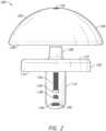
- a prosthesis or implant 100 for example, a humeral prosthesis or humeral implant.
- Methods for implanting and removing the implant 100 are also disclosed.
- the prosthesis 100 includes a baseplate 102 (see FIGS. 1-8 ) for connection to a bone, an articulating component 104 (see FIGS. 1-8 ) for attaching to the baseplate 102, and a fixation component 106 (see FIGS. 1-6 ) for engaging a through hole 130 (see FIGS. 2 and 4 ) in the articulating component 104 to couple the baseplate 102 and the articulating component 104.
- the baseplate 102 includes a projection 108 (see FIGS. 1-4 and 6 ) extending from a first side 110 (see FIGS. 1 , 2 , 4 , and 6 ) of the baseplate 102.
- the projection 108 may be, for example, a Morse taper.
- the projection 108 may have a taper, for example, ranging between approximately 1° to 8°, as the projection 108 extends away from the baseplate 102.
- the projection 108 is offset from a diametric center 112 (see FIG. 1 ) of the baseplate 102.
- the projection 108 may have, for example, a height and a diameter and the height may be larger than the diameter.
- the baseplate 102 includes a post or stem 114 (see FIGS. 1-8 ) on a second side 116 (see FIGS. 1-3 and 5-8 ).
- the post 114 is also offset relative to the center 112 of the baseplate 102, for example, diametrically offset from the projection 108.
- the post 114 extends away from the second side 116 of the baseplate 102 to an end 118 of the post 114.
- the post 114 may be used to attach the baseplate 102 to the bone or to stabilize the baseplate 102 within a scapula or humerus.
- the post 114 may be of any length or cross sectional geometry necessary to be received within a bone and may be secured within the bone by any means, including but not limited to a surface treatment or structural elements, including ridges, fins, etc.
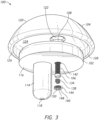
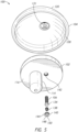
- the articulating component 104 may be, for example, a spherical shaped articulating component 104.
- the articulating component 104 attaches to the baseplate 102, can include, for example, a substantially convex side or articulating surface 120.
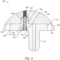
- a cutaway view shows that the articulating component 104 includes a corresponding opening or cavity 122 for engaging or receiving the projection 108 of the baseplate 102.
- the opening 122 may be, for example, a corresponding Morse taper.
- the opening 122 (see FIGS. 3 , 5 , and 6 ) may be offset from a diametric center of the articulating component 104. As illustrated in FIG.
- the articulating component 104 may include a recess 124 on the opposing side of the convex side 120 for accepting a top portion of the baseplate 102.
- the recess 124 may, for example, provide clearance around the baseplate 102 for inserting screws (not shown).
- the recess 124 allows for the base plate 102 to be inset into the articulating component 104 to position the engagement of the base plate 102 and articulating component 104 adjacent to the patient's bone.
- the articulating component 104 may also include a lip 126 about the diameter of the flat side 128 of the articulating component 104. The flat side 128 opposes the convex side 120.
- the articulating component 104 can include a through hole 130 (see FIGS. 2 , 4 , and 6 ) extending from a first side, for instance the flat side 128, to a second side, for instance the convex side 120, of the articulating component 104.
- the through hole 130 may be threaded with a set of threads 131 as seen in the cutaway of FIG. 6 , as well as in FIGS. 2 , 4 , and 5 . In some embodiments, the through hole 130 is aligned with the cavity 122 as illustrated in FIG. 6 .
- the fixation component 106 may engage or be configured to engage the through hole 130 in the articulating component 104.
- the fixation component 106 may also connect the baseplate 102 and the articulating component 104.
- the fixation component 106 may include, for example, any screw or like structure.
- the fixation component 106 may be contained within a cavity 132 of the baseplate 102.
- the cavity 132 of the baseplate 102 is aligned with and contained partially within the projection 108 of the baseplate 102.
- the fixation component 106 may include a widened head 134, which may engage a lip 136 within the cavity 132.
- the cap 140 may engage a threaded portion 142 of the cavity 132 to capture the spring 138 and the fixation component 106, which when assembled may fit flush on the second side 116 of the baseplate 102, as illustrated in FIGS. 6-8 .
- the cap 140, spring 138, and fixation component 106 may be preassembled before purchase of the prosthesis 100, limiting the number of parts needing to be assembled in the operating room.
- the circumference 144 of cap 140 may be threaded in order to engage the threaded portion 142 of baseplate 102.
- the internal surface 146 of cap 140 may be flat where the cap 140 will contact the spring 138.
- the external surface 148 of cap 140 may include an engagement surface 150, which may have, for example, any surface, shape, or feature for coupling or securing the cap 140 to the threaded portion 142 of baseplate 102.
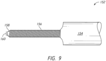
- the extraction device 152 may include a handle 154, for example, a circular end.
- the handle 154 may be, for example, a handle for rotating the extraction device 152 or alternatively, a coupling component for engaging a rotating device, such as a drill.
- Extending from the handle 154 may be a threaded portion 156, for engaging a set of threads 131 in the articulating component 104 of the prosthesis 100.
- the threaded portion 156 can be inserted into the through hole 130 of the articulating component 104 by engaging the threads 131 from the convex side 120, opposite the direction of the fixation component 106.
- the tip 158 of the extraction device 152 may have an engagement projection 160.
- the tip of the fixation component 106 may have an engagement recess 162.
- the engagement projection 160 may have a cross-sectional shape of, for example, hexagonal, square, or the like to engage the engagement recess 162 of the fixation component to effectively push the fixation component 106 out of the flat side 128 of the articulating component 104 against the force of the spring 138 as the extraction device 152 is rotated. This will allow for the uncoupling of the articulating component 104 from the baseplate 102 via the extraction device 152 without any force being applied against the bone implant interface.
- baseplates according to the embodiments above may be positioned within a scapula. Although described as a reverse shoulder replacement, it should be understood that the baseplate can be positioned in the proximal humerus as well, providing an articulating convex surface in its correct anatomic placement.
- an articulating component as in the above embodiments can be attached to the baseplate, using a hole extending from a first side of the articulating component to a second side of the articulating component, and threaded to receive a fixation component contained within the baseplate.
- the implant 200 may be, for example, a humeral prosthesis or humeral implant.
- the implant 200 includes an articulating member or component 210, a base member or portion 230, and a coupling portion 260 for connecting the articulating member 210 to the base member 230.
- the articulating member 210 may include an articulating surface 212 and an interior surface 214.
- the articulating surface or exterior surface 212 may, for example, have a convex or half spherical shape.
- the interior surface, flat side, or engagement portion 214 may include an outer lip or lip 216 surrounding the exterior portion of the interior surface 214.
- the outer lip 216 may include, for example, a width and the width may vary around the circumference of the lip 216.
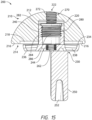
- the interior surface 214 may also include a recess 218 positioned within the lip 216 and sized and shaped or configured to receive a portion of the base member 230, as shown in FIG. 15 and 17 .
- the interior surface 214 may further include a cavity 220 extending into the articulating member 210 from the recess 218 toward the articulating surface 212, as shown in FIGS. 12 , 13 and 15 .
- the cavity 220 may extend, for example, through only a portion of the articulating member 210 or, alternatively, from the recess 218 entirely through the articulating surface 212 forming a through hole.
- the cavity 220 may be, for example, positioned at a center of the articulating member 210, as shown. Alternatively, it is contemplated that the cavity 220 may be positioned, for example, offset from the center, such as, being shifted anteriorly, to allow for building an offset away from the scapula.
- the articulating member 210 may also include a threaded portion or threads 222.
- the threaded portion or threads 222 may, for example, extend along at least a portion of the interior surface of the cavity 220 or, alternatively, the threaded portion or threads 222 may be positioned adjacent to the cavity 220.
- the threaded portion 222 extends from a bottom of the cavity 220 through the articulating member 210 to the articulating surface 212.
- the threaded portion 222 may have, for example, a diameter smaller than the diameter of the cavity 220.
- the cavity 220 and threaded portion 222 may together form a through hole extending from the interior surface 214 through the articulating member 210 to the articulating surface 212, as shown in FIG. 15 .
- the cavity 220 may be, for example, tapered as it extends from the interior surface 214 of the articulating member 210 toward the articulating surface 212.
- the cavity 220 may have, for example, a height and a first width or diameter at a first end and the height may be larger than the first width.
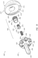
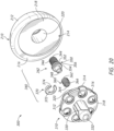
- the base member or base portion 230 is shown in FIGS. 10-18 .
- the base member 230 includes a plate portion 232 with a top surface 234 and a bottom surface 236.
- the plate portion 232 may also include a plurality of openings or through holes 238 extending through the plate portion 232 from a top surface 234 to the bottom surface 236, as shown in FIGS. 12-17 .
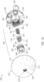
- the base member 230 also includes a projection 240 extending away from the top surface 234 of the plate portion 232, as shown in FIGS. 10-15 .
- the projection 240 may be positioned, for example, generally centered on the top surface 234 of the plate portion 232 with the plurality of openings 238 positioned around the exterior surface of the projection 240, as shown in FIG. 14 .
- the projection 240 may be, for example, tapered as it extends away from the top surface 234 of the base member 230.
- the projection 240 may have a taper, for example, ranging between approximately 1° to 8°, as the projection 240 extends away from the base member 230.
- the projection 240 may have, for example, a height and a first width or diameter positioned where the projection 240 couples to the plate portion 232 and the height may be larger than the first diameter.
- the projection 240 may also include a cavity or opening 242 extending into the projection 240 from a first or top end, as shown in FIGS. 14 and 15 . With continued reference to FIGS.
- the cavity 242 may further include a recess or spring opening 244 in a bottom surface of the cavity 242.
- the recess 244 may, for example, extend into the top surface 234 of the plate portion 232, as shown in FIG. 15 .
- the cavity 242 may also include threads 246, for example, along at least a portion of the interior wall of the cavity 242.
- the threads 246 may extend, for example, between a top of the projection 240 down to a bottom surface of the cavity 242 or along any portion of the interior surface of the cavity 242 between the top of the projection 240 to the bottom surface, as shown in FIGS. 14 and 15 .
- the base member 230 further includes a stem 250, as shown in FIGS. 10-18 .
- the stem 250 extends away from the bottom surface 236 of the plate portion 232.
- the stem 250 is offset from the center of the bottom surface 236 of the plate portion 232, as shown in FIGS. 10 and 12-17 .
- the stem 250 may be offset from the projection 240 in at least one direction from the diametric center, as shown in FIGS. 10 , 12 , 14 , and 15 .
- the stem 250 may also, be positioned between two openings 238, as shown in FIGS. 13 and 16 .
- the stem 250 may further include an opening 252 extending from the distal end into the stem 250, as shown in FIGS. 12 , 13 , and 15-17 .
- the opening 252 may be, for example, tapered as the opening 252 extends toward the plate portion 232.
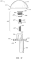
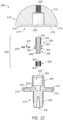
- the coupling portion 260 includes a spring or elastic member 262, a first fixation component or articulating coupler 270, and a second fixation component or base coupler 280.
- a first end of the first fixation component 270 receives at least a portion of the spring 262 and a second end of the first fixation component 270 passes through the second fixation component 280, as shown in FIG. 15 .
- At least a portion of the engaged or coupled spring 262 and first fixation component 270 are received within the second fixation component 280.
- the spring 262 may include a first end 264 for engaging the first fixation component 270 and a second end 266 for engaging the recess 244 in the base member 230, as shown in FIG. 15 .
- the first fixation component 270 may include a threaded portion 272 at a first end and a stop member or end member 274 at a second end, as shown in FIGS. 10 , 11 , 13 and 14 .
- the threads of the threaded portion 272 may extend, for example, from the first end to the stop member 274 or, alternatively, from the first end toward the stop member 274 along only a portion of the first fixation component 270, as shown in FIGS. 10 , 11 , 13 and 14 .
- the first fixation component 270 may also include a drive opening 276.
- the drive opening 276 may be sized and shaped or configured to receive an instrument or driver for coupling and removing the first fixation component 270 from articulating member 210, as shown in FIG. 15 .
- the drive opening 276 may be, for example, hexagonal, square, Phillips or another multi-lobed configuration for coupling with an instrument.
- the second end of the first fixation component 270 may include a recess, spring cavity or spring opening 278, as shown in FIG. 13 .
- the recess 278 may be, for example, inset into the stop member 274 of the first fixation component 270. Further, the recess 278 may be sized and shaped or configured to receive the first end 264 of the spring 262, as shown in FIG. 15 .
- the second fixation component or base coupler 280 is shown in FIGS. 10 , 11 , and 13-15 .
- the second fixation component 280 may include a head portion 282 at a first end and a body 284 extending away from the head portion 282 to the second end.
- the body 284 may include threads 286 along at least a portion of the body 284.
- the threads 286 may extend from the head portion 282 toward the second end on the exterior surface of the second fixation component 280 along only a portion of the body 284, as shown in FIGS. 10 , 11 , 13 and 14 .
- the threads 286 may extend from the head portion 282 to the second end on the exterior surface of the body 284 of the second fixation component 280.
- the second fixation component 280 may also include a drive opening 288 on the first end, as shown in FIG. 14 , for receiving an instrument or driver.
- the drive opening 288 may be, for example, hexagonal, square, Phillips or another multi-lobed configuration for coupling with an instrument.
- the second fixation component 280 may also include an opening or through hole 290 extending from the drive opening 288 at the first end to the second end, as shown in FIG. 13 .
- the opening 290 may be, for example, sized and shaped or configured to receive the first fixation component 270, as shown in FIG. 15 .
- the drive opening 288 may be sized and shaped or configured to allow the threaded portion 272 of the first fixation component 270 to extend out the first end of the second fixation component 280, as shown in FIG. 15 .
- the opening 290 may have, for example, a diameter larger than the width of the drive opening 288 to prevent the stop member 274 of the first fixation component 270 from passing through the interior of the second fixation component 280.
- a method of assembling the implant 200 is also disclosed.
- the method may include inserting the first fixation component 270 into the opening 290 of the second fixation component 280.
- the method may also include inserting the first end 264 of the spring 262 into the recess 278 of the first fixation component 270 to form the coupling member 260.
- the method may further include inserting the second end 266 of the spring 262 into the spring opening 244 in the base member 230 and coupling the threads 286 of the body 284 of the second fixation member 280 with the threads 246 in the cavity 242 of the base member 230.
- This arrangement of the coupling portion 260 creates a biasing force to push the first fixation component 270 out of the second fixation component 280 to be able to engage the articulating component 210. Therefore, after securing the coupling member 260 to the base member 230, at least a part of the threaded portion 272 will extend out of the first end of the second fixation component 280.
- the base member 230 and secured coupling member 260 may be inserted into the patient and then the articulating member 210 may be coupled to the base member 230.
- the cavity 220 of the articulating member 210 may be aligned over the projection 240 of the base member 230.
- the articulating member 210 may be coupled to the base member 230 by applying a force to the articulating member 210 to engage the cavity 220 with the projection 240.
- an instrument (not shown) may be used to force the articulating member 210 into place on the base member 230.
- the spring 262 of the coupling member 260 may be compressed.
- the first fixation component 270 may be rotated to thread the threaded portion 272 of the first fixation component 270 into the threads 222 of the articulating member 210. If the base member 230 wasn't already inserted into a patient, once the articulating member 210 and base member 230 are each coupled to the coupling portion 260, the implant 200 may be inserted into a patient.
- base member 230 may be positioned within a scapula. Although described as a reverse shoulder replacement, it should be understood that the base members 230 can be positioned in the proximal humerus as well, providing an articulating convex surface in its correct anatomic placement.
- an articulating member 210 as in the above embodiment can be attached to the base member 230, using the projection 240 of the base member 230, cavity 220 of the articulating member 210, and a coupling portion 260 engaging the articulating member 210 and the base member 230, as described in greater detail above with reference to FIGS.
- the coupling portion 260 is attached to the base portion 230 and inserted into a patient, the surgeon is able to couple the articulating member 210 to the coupling portion 260 and the base portion 230 without having to find an opening in the articulating member 210 to insert additional screws.
- the shape and size of the cavity 220 in the articulating member 210 may correspond to the shape and size of the projection 240 of the base member 230 to, for example, assist with preventing malalignment during insertion of the implant.
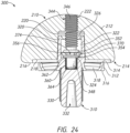
- the implant 300 may be, for example, a humeral prosthesis or humeral implant.
- the implant 300 includes an articulating member or component 210, a base member or portion 310, and a coupling portion 340 for connecting the articulating member 210 to the base member 310.
- the articulating member 210 may be of the type described above with reference to FIGS. 10-18 . As described in greater detail above and which will not be described again here for brevity sake, the articulating member 210 may include an articulating surface or exterior surface 212 and an interior surface, flat side, or engagement portion 214 with the outer lip or lip 216, the recess 218, and the cavity 220, as shown in FIG. 20 and 22-24 . The articulating member 210 may also include a threaded portion or threads 222.
- the base member or base portion 310 is shown in FIGS. 19-24 .
- the base member 310 includes a plate portion 312 with a top surface 314 and a bottom surface 316.
- the plate portion 312 may also include a plurality of openings or through holes 318 extending through the plate portion 312 from a top surface 314 to the bottom surface 316, as shown in FIGS. 19 , 20 , and 22-24 .
- the base member 310 also includes a projection 320 extending away from the top surface 314 of the plate portion 312, as shown in FIGS. 19 and 21-24 .
- the projection 320 may be positioned, for example, generally centered on the top surface 314 of the plate portion 312 with the plurality of openings 318 positioned around the exterior surface of the projection 320, as shown in FIGS. 19 and 20 .
- the projection 320 may be, for example, tapered as it extends away from the top surface 314 of the base member 310.
- the projection 320 may have a taper, for example, ranging between approximately 1° to 8°, as the projection 320 extends away from the base member 310.
- the projection 320 may have, for example, a height and a first width or diameter positioned where the projection 320 couples to the plate portion 312 and the height may be larger than the first diameter.
- the projection 320 may also include a cavity or opening 322 extending into the projection 320 from a first or top end, as shown in FIGS. 19 and 22-24 .
- the cavity 322 may further include a recess or spring opening 324 in a bottom surface of the cavity 322.
- the recess 324 may, for example, extend into the top surface 314 of the plate portion 312, as shown in FIGS. 22-24 .
- the cavity 322 may also include a retaining member or rim 326, for example, positioned near a top of the interior wall of the cavity 322.
- the retaining member 326 may, for example, be chamfered or angled on a top surface and flat or perpendicular to the interior side wall of the cavity 322, as shown in FIG. 22 .
- the opening extending through the retaining member 326 may include a diameter smaller than the diameter of the cavity 322 to engage the coupling portion 340 for securing the articulating member 210 to the base member 310.
- the base member 310 further includes a stem 330, as shown in FIGS. 19-24 .
- the stem 330 extends away from the bottom surface 316 of the plate portion 312.
- the stem 330 may be, for example, centered on the bottom surface 316 of the plate portion 312, as shown in FIGS. 20-24 .
- the stem 330 may be aligned with the projection 320, as shown in FIGS. 21-24 .
- the stem 330 may also, be positioned centered between all of the openings 318, as shown in FIG. 20 .
- the stem 330 is offset as described in greater detail above with respect to stem 250 and which will not be described again here for brevity sake.
- the stem 330 may further include an opening 332 extending from the distal end into the stem 330, as shown in FIGS. 20 and 22-24 .
- the opening 332 may be, for example, tapered as the opening 332 extends toward the plate portion 312.
- the coupling portion 340 includes a securement member or locking bolt 342, a spring or elastic member 360, and an engagement member 370.
- the securement member 342 may include a first portion 344 positioned at a first end, a second portion 346 positioned at a second end, and an intermediate portion 350 positioned between the first portion 344 and the second portion 346.
- the first portion 344 may include threads 346 positioned along, for example, at least a section of the first portion 344 between the first end and the intermediate portion 350.
- the second portion 348 may have a diameter, for example, to receive the spring 360.
- the intermediate portion 350 may include, for example, a first protrusion 352 extending circumferentially away from the body of the securement member 342 and a second protrusion 354 extending circumferentially away from the body of the securement member 342.
- the first protrusion 352 may be spaced apart from the second protrusion 354 forming a recess or channel 356 between the protrusions 352, 354.
- the recess or channel 356 may be, for example, sized to receive the engagement member 370.
- a method, not in accordance with the appended claims, of assembling the implant 300 is also disclosed.
- the method may include forming the coupling member 340.
- Forming the coupling member 340 may include inserting the second portion 348 of the securement member 342 into the through hole 366 of the spring 360 at the first end 362.
- Forming the coupling member 340 may also include aligning the slot 374 of the engagement member 370 with the recess 356 in the securement member 342 and inserting the engagement member 370 into the recess 356 of the securement member 342.
- the method may also include inserting the second portion 348 of the securement member 342 into the cavity 322 in the base member 310.
- the second end 364 of the spring 360 may be inserted into the recess 324 in the base member 310 and the engagement member 370 may be inserted into the cavity 322 past the retaining member 326.
- the engagement member 370 may deflect to pass the retaining member 326. Once the engagement member 370 passes the retaining member 326, the engagement member 370 will expand to the original size and secure the securement member 342 to the base member 310, as shown in FIGS. 23 and 24 .
- the securement member 342 may translate within the cavity 322 with respect to the force applied to the spring 360 until the engagement member 370 engages the retaining member 326.
- At least part of the first portion 344 will extend out from the projection 320 of the base member 310 to engage the articulating member 210, as shown in FIGS. 23 and 24 .
- the base member 310 and secured coupling member 340 may be inserted into the patient and then the articulating member 210 may be coupled to the base member 310.
- the coupling portion 340 is coupled to the base portion 310 and inserted into a patient, the surgeon is able to attach the articulating member 210 to the coupling portion 340 and the base portion 310 without having to find an opening in the articulating member 210 to insert additional screws.
- the shape and size of the cavity 220 in the articulating member 210 may correspond to the shape and size of the projection 320 of the base member 310 to, for example, assist with preventing malalignment during insertion of the implant.
- a method or device that "comprises,” “has,” “includes,” or “contains” one or more steps or elements possesses those one or more steps or elements, but is not limited to possessing only those one or more steps or elements.
- a step of a method or an element of a device that "comprises,” “has,” “includes,” or “contains” one or more features possesses those one or more features, but is not limited to possessing only those one or more features.
- a device or structure that is configured in a certain way is configured in at least that way, but may also be configured in ways that are not listed.
Landscapes
- Health & Medical Sciences (AREA)
- Transplantation (AREA)
- Orthopedic Medicine & Surgery (AREA)
- Vascular Medicine (AREA)
- Animal Behavior & Ethology (AREA)
- Engineering & Computer Science (AREA)
- Biomedical Technology (AREA)
- Heart & Thoracic Surgery (AREA)
- Cardiology (AREA)
- Life Sciences & Earth Sciences (AREA)
- Oral & Maxillofacial Surgery (AREA)
- General Health & Medical Sciences (AREA)
- Public Health (AREA)
- Veterinary Medicine (AREA)
- Physical Education & Sports Medicine (AREA)
- Prostheses (AREA)
- Dental Prosthetics (AREA)
Claims (13)
- Ein Implantat (100, 200, 300), umfassend:ein Basiselement (102, 230, 310) umfassend:einen Plattenabschnitt (102, 232, 312) mit einer ersten Seite (110, 234, 314) und einer gegenüberliegenden zweiten Seite (116, 236, 316),einen Vorsprung (108, 240, 320), der sich von der ersten Seite des Plattenabschnitts erstreckt, wobei der Vorsprung von einer Mitte (112) des Plattenabschnitts versetzt ist, undeinen Stiel (114, 250, 330), der sich von der zweiten Seite (116, 236, 316) des Plattenabschnitts erstreckt, wobei der Stiel von der Mitte (112) des Plattenabschnitts (102, 232, 312) versetzt angeordnet ist und so bemessen und konfiguriert ist, dass er das Basiselement im Knochen befestigt;ein Gelenkelement (104, 210), das einen Gelenkelementhohlraum (122, 220) und ein Loch (130, 222) definiert, wobei der
Hohlraum so bemessen und konfiguriert ist, dass er den Vorsprung aufnimmt, der sich von der ersten Seite des Plattenabschnitts erstreckt, und das Loch, das sich durch den Hohlraum erstreckt; undeinen Kupplungsabschnitt (106, 138, 140, 260, 340), der so bemessen und konfiguriert ist, dass er in dem durch das Gelenkelement definierten Loch aufgenommen werden kann, um das Basiselement an dem Gelenkelement zu befestigen. - Implantat nach Anspruch 1, wobei das Gelenkelement eine Außenfläche (120, 212) und eine Innenfläche (124, 214) aufweist und wobei sich der Hohlraum des Gelenkelements von der Innenfläche aus in das Gelenkelement erstreckt.
- Implantat nach Anspruch 2, wobei der Kupplungsabschnitt Folgendes umfasst:eine erste Fixierungskomponente (106, 270, 342); undeine zweite Fixierungskomponente (280) mit einer Öffnung (290) zur Aufnahme der ersten Fixierungskomponente.
- Implantat nach Anspruch 3, wobei die erste Fixierungskomponente (106, 270, 342) in der durch die zweite Fixierungskomponente (280) definierten Öffnung (290) aufgenommen wird und ein Teil der ersten Fixierungskomponente sich von einem ersten Ende der zweiten Fixierungskomponente aus erstreckt.
- Implantat nach Anspruch 3, wobei der Kupplungsabschnitt ferner Folgendes umfasst:
ein elastisches Element (138, 262, 360) mit einem ersten Ende und einem zweiten Ende, wobei das erste Ende des elastischen Elements in ein zweites Ende der ersten Fixierungskomponente (106, 270, 342) eingreift und das zweite Ende des elastischen Elements in eine Ausnehmung (244, 324)
innerhalb des Vorsprungs des Basiselements eingreift. - Implantat nach Anspruch 5, wobei die zweite Fixierungskomponente (280) mit dem Vorsprung des Basiselements gekoppelt ist, der Vorsprung des Basiselements mit dem gekoppelten Kupplungsabschnitt innerhalb des Hohlraums des Gelenkelements positioniert ist und die erste Fixierungskomponente mit dem Gelenkelement gekoppelt ist.
- Implantat nach Anspruch 6, wobei der Plattenabschnitt innerhalb einer Lippe (126, 216) angeordnet ist, die sich von der Innenfläche des Gelenkelements aus erstreckt.
- Implantat nach Anspruch 7, wobei die Lippe eine Breite aufweist und die Breite um den Umfang der Innenfläche des Gelenkelements variiert.
- Implantat nach Anspruch 2, wobei der Kupplungsabschnitt Folgendes umfasst:ein Sicherungselement (342) mit einem ersten Abschnitt (344) an einem ersten Ende, einem zweiten Abschnitt (348) an einem zweiten Ende und einem Zwischenabschnitt (350), der zwischen dem ersten Abschnitt und dem zweiten Abschnitt angeordnet ist;ein elastisches Element (360), das mit mindestens einem Teil des zweiten Abschnitts in Eingriff steht; undein Eingriffselement (370), das mit dem Zwischenabschnitt verbunden ist.
- Das Implantat nach Anspruch 9, wobei der erste Abschnitt entlang mindestens eines Teils des ersten Abschnitts Gewinde aufweist.
- Implantat nach Anspruch 9, wobei der Zwischenabschnitt ferner Folgendes umfasst:einen ersten Vorsprung (352), der mit einem zweiten Ende des ersten Abschnitts verbunden ist;einen zweiten Vorsprung (354), der mit einem ersten Ende des zweiten Abschnitts verbunden ist; undeinen Kanal
(356) zwischen dem ersten Vorsprung und dem zweiten Vorsprung, wobei der Kanal das Eingriffselement aufnimmt. - Das Implantat nach Anspruch 11, wobei der Vorsprung des Basiselements umfasst:einen vorspringenden Hohlraum (242, 322)der sich in den Vorsprung von einer oberen Fläche des Vorsprungs in Richtung der ersten Seite des Plattenabschnitts erstreckt; undein Halteelement (326), das um den durch den Vorsprung des Basiselements definierten Hohlraum herum angeordnet ist und sich in diesen hinein erstreckt in der Nähe der oberen Fläche des Vorsprungs.
- Implantat nach Anspruch 12, wobei der erste Vorsprung des Zwischenabschnitts an einer Bodenfläche des Halteelements des Basiselements anliegt.
Priority Applications (1)
| Application Number | Priority Date | Filing Date | Title |
|---|---|---|---|
| EP24219566.7A EP4497417A3 (de) | 2017-10-16 | 2018-10-11 | Schulterimplantate sowie verfahren zur verwendung und anordnung |
Applications Claiming Priority (2)
| Application Number | Priority Date | Filing Date | Title |
|---|---|---|---|
| US201762572920P | 2017-10-16 | 2017-10-16 | |
| PCT/US2018/055490 WO2019079104A2 (en) | 2017-10-16 | 2018-10-11 | SHOULDER IMPLANTS AND METHODS OF USE AND ASSEMBLY |
Related Child Applications (2)
| Application Number | Title | Priority Date | Filing Date |
|---|---|---|---|
| EP24219566.7A Division EP4497417A3 (de) | 2017-10-16 | 2018-10-11 | Schulterimplantate sowie verfahren zur verwendung und anordnung |
| EP24219566.7A Division-Into EP4497417A3 (de) | 2017-10-16 | 2018-10-11 | Schulterimplantate sowie verfahren zur verwendung und anordnung |
Publications (2)
| Publication Number | Publication Date |
|---|---|
| EP3697347A2 EP3697347A2 (de) | 2020-08-26 |
| EP3697347B1 true EP3697347B1 (de) | 2025-03-26 |
Family
ID=64049753
Family Applications (2)
| Application Number | Title | Priority Date | Filing Date |
|---|---|---|---|
| EP18795911.9A Active EP3697347B1 (de) | 2017-10-16 | 2018-10-11 | Schulterimplantate |
| EP24219566.7A Pending EP4497417A3 (de) | 2017-10-16 | 2018-10-11 | Schulterimplantate sowie verfahren zur verwendung und anordnung |
Family Applications After (1)
| Application Number | Title | Priority Date | Filing Date |
|---|---|---|---|
| EP24219566.7A Pending EP4497417A3 (de) | 2017-10-16 | 2018-10-11 | Schulterimplantate sowie verfahren zur verwendung und anordnung |
Country Status (4)
| Country | Link |
|---|---|
| US (2) | US11564802B2 (de) |
| EP (2) | EP3697347B1 (de) |
| CA (1) | CA3079099A1 (de) |
| WO (1) | WO2019079104A2 (de) |
Families Citing this family (33)
| Publication number | Priority date | Publication date | Assignee | Title |
|---|---|---|---|---|
| US8388624B2 (en) | 2003-02-24 | 2013-03-05 | Arthrosurface Incorporated | Trochlear resurfacing system and method |
| US8778028B2 (en) | 2005-02-25 | 2014-07-15 | Shoulder Innovations, Inc. | Methods and devices for less invasive glenoid replacement |
| US20230080207A1 (en) | 2005-02-25 | 2023-03-16 | Shoulder Innovations, Inc. | Methods and devices for less invasive glenoid replacement |
| CA2686814A1 (en) | 2006-12-11 | 2008-06-19 | Arthrosurface Incorporated | Retrograde resection apparatus and method |
| WO2016154393A1 (en) | 2009-04-17 | 2016-09-29 | Arthrosurface Incorporated | Glenoid repair system and methods of use thereof |
| US9662126B2 (en) | 2009-04-17 | 2017-05-30 | Arthrosurface Incorporated | Glenoid resurfacing system and method |
| FR2955247B1 (fr) | 2010-01-21 | 2013-04-26 | Tornier Sa | Composant glenoidien de prothese d'epaule |
| EP2542165A4 (de) | 2010-03-05 | 2015-10-07 | Arthrosurface Inc | Schienbein-oberflächenersatzsystem und -verfahren |
| FR2971144A1 (fr) | 2011-02-08 | 2012-08-10 | Tornier Sa | Implant glenoidien pour prothese d'epaule et kit chirurgical |
| EP2804565B1 (de) | 2011-12-22 | 2018-03-07 | Arthrosurface Incorporated | System zur knochenfixierung |
| WO2014008126A1 (en) | 2012-07-03 | 2014-01-09 | Arthrosurface Incorporated | System and method for joint resurfacing and repair |
| US9492200B2 (en) | 2013-04-16 | 2016-11-15 | Arthrosurface Incorporated | Suture system and method |
| EP3777777B1 (de) | 2014-01-03 | 2023-04-05 | Howmedica Osteonics Corp. | Schultergelenkspfannenimplantat für schulterprothese |
| US11607319B2 (en) | 2014-03-07 | 2023-03-21 | Arthrosurface Incorporated | System and method for repairing articular surfaces |
| US9962265B2 (en) | 2014-03-07 | 2018-05-08 | Arthrosurface Incorporated | System and method for repairing articular surfaces |
| EP4233740A3 (de) | 2016-08-24 | 2023-09-27 | Howmedica Osteonics Corp. | Humeruskopfimplantatsystem |
| WO2018183484A1 (en) | 2017-03-31 | 2018-10-04 | Tornier, Inc. | Modular humeral head |
| US11160663B2 (en) | 2017-08-04 | 2021-11-02 | Arthrosurface Incorporated | Multicomponent articular surface implant |
| EP3697347B1 (de) * | 2017-10-16 | 2025-03-26 | Stryker European Operations Limited | Schulterimplantate |
| EP4438012A3 (de) | 2018-04-30 | 2024-10-16 | Shoulder Innovations, Inc. | Inset/onlay-glenoid, poröses beschichtetes umwandelbares glenoid und humerusköpfe mit strukturierten unterseiten |
| EP3860523B1 (de) | 2018-10-02 | 2024-07-17 | Howmedica Osteonics Corp. | Modularer oberarmkopf |
| US12370052B2 (en) | 2018-10-02 | 2025-07-29 | Howmedica Osteonics Corp. | Modular humeral head |
| JP7691369B2 (ja) * | 2019-03-11 | 2025-06-11 | ショルダー・イノベーションズ・インコーポレイテッド | 全リバースショルダーシステムおよび方法 |
| US11478358B2 (en) | 2019-03-12 | 2022-10-25 | Arthrosurface Incorporated | Humeral and glenoid articular surface implant systems and methods |
| AU2020276186C1 (en) * | 2019-05-13 | 2022-07-21 | Howmedica Osteonics Corp. | Glenoid baseplate and implant assemblies |
| IT201900009015A1 (it) * | 2019-06-14 | 2020-12-14 | Limacorporate Spa | Adattatore glenoidale perfezionato per protesi dell’articolazione della spalla |
| US12433755B2 (en) * | 2019-06-14 | 2025-10-07 | Arthrosurface Incorporated | Articular surface implant systems and methods including glenoid reverse shoulder |
| JP7478810B2 (ja) | 2019-08-09 | 2024-05-07 | ハウメディカ オステオニクス コーポレイション | 肩の手術用のキット |
| AU2021202801A1 (en) | 2020-05-07 | 2021-11-25 | Howmedica Osteonics Corp. | Stemless metaphyseal humeral implant |
| IL304666B1 (en) * | 2021-01-27 | 2025-10-01 | Skeletal Dynamics Inc | Reverse shoulder prosthesis and related methods |
| WO2024015899A2 (en) * | 2022-07-14 | 2024-01-18 | Howmedica Osteonics Corp. | Monolithic baseplate |
| US20240099853A1 (en) * | 2022-09-28 | 2024-03-28 | Wright Medical Technology, Inc. | Implants with modular stems with tension/compression mechanisms |
| FR3150099B1 (fr) * | 2023-06-26 | 2025-10-24 | Geoffroy Guerin | Dispositif de réglage pour prothèse d’articulation |
Family Cites Families (196)
| Publication number | Priority date | Publication date | Assignee | Title |
|---|---|---|---|---|
| FR2567019A1 (fr) | 1984-07-06 | 1986-01-10 | Fournier Gilles | Mode de contention des pieces d'une endoprothese articulaire |
| US4725280A (en) | 1986-03-28 | 1988-02-16 | Laure Prosthetics, Inc. | Finger implant |
| US5080673A (en) | 1988-02-03 | 1992-01-14 | Intermedics Orthopedics, Inc. | Glenoid prosthesis and method of use |
| JP3017744B2 (ja) | 1989-03-09 | 2000-03-13 | パイオニア株式会社 | ボイスチェンジ回路 |
| US4986833A (en) | 1989-05-05 | 1991-01-22 | Worland Richard L | Glenoid component for an artificial shoulder joint |
| US5032132A (en) | 1990-01-22 | 1991-07-16 | Boehringer Mannheim Corporation | Glenoid component |
| US5108446A (en) | 1990-11-26 | 1992-04-28 | Sulzer Brothers Limited | Hip joint prosthesis |
| US6102954A (en) | 1992-05-18 | 2000-08-15 | Astra Aktiebolag | Joint prosthesis and apparatus for preparing the bone prior to fitting of the prosthesis |
| FR2694186B1 (fr) | 1992-07-29 | 1994-09-16 | Science Medecine | Prothèse de glène vissée et procédé de mise en place. |
| US5489309A (en) | 1993-01-06 | 1996-02-06 | Smith & Nephew Richards Inc. | Modular humeral component system |
| US6197065B1 (en) | 1993-11-01 | 2001-03-06 | Biomet, Inc. | Method and apparatus for segmental bone replacement |
| US5489311A (en) | 1994-01-21 | 1996-02-06 | Joint Medical Products Corporation | Prosthesis with orientable bearing surface |
| JPH08957A (ja) | 1994-02-18 | 1996-01-09 | Babcock & Wilcox Co:The | 分子窒素及び炭化水素混合物からのプラズマ発生NOx還元性先駆物質の製造 |
| US5458637A (en) | 1994-11-21 | 1995-10-17 | Zimmer, Inc. | Orthopaedic base component with modular augmentation block |
| FR2739151B1 (fr) | 1995-09-22 | 1997-11-28 | Numedic | Dispositif de solidarisation d'une piece sur un support |
| FR2741796B1 (fr) | 1995-11-30 | 1998-03-27 | Tornier Sa | Dispositif pour la fixation d'une prothese et notamment d'une prothese glenoidienne de l'omoplate |
| US5662657A (en) | 1996-01-17 | 1997-09-02 | Sunmed, Inc. | Intramedullary bone plug |
| US6171342B1 (en) | 1996-07-23 | 2001-01-09 | Depuy Orthopaedics, Inc. | Medical fastening system |
| US8480754B2 (en) | 2001-05-25 | 2013-07-09 | Conformis, Inc. | Patient-adapted and improved articular implants, designs and related guide tools |
| AU6145998A (en) * | 1997-02-11 | 1998-08-26 | Gary Karlin Michelson | Skeletal plating system |
| US5800551A (en) | 1997-03-10 | 1998-09-01 | Biomet, Inc. | Apparatus and method for shoulder arthroplasty |
| US5954722A (en) | 1997-07-29 | 1999-09-21 | Depuy Acromed, Inc. | Polyaxial locking plate |
| US6454769B2 (en) | 1997-08-04 | 2002-09-24 | Spinal Concepts, Inc. | System and method for stabilizing the human spine with a bone plate |
| US6379386B1 (en) | 1997-09-09 | 2002-04-30 | Stryker Technologies Corporation | Anatomic glenoid shoulder prosthesis together with methods and tools for implanting same |
| FR2773469B1 (fr) | 1998-01-09 | 2000-03-03 | Alain Leonard | Equipement chirurgical pour l'implantation d'une prothese totale d'epaule, et prothese totale d'epaule constitutive |
| FR2776506B1 (fr) | 1998-03-25 | 2000-08-18 | Depuy France | Prothese glenoidienne d'epaule et son ancillaire de pose |
| US6228119B1 (en) | 1998-06-09 | 2001-05-08 | Depuy Orthopaedics, Inc. | Modular glenoid assembly |
| DE59907882D1 (de) * | 1998-09-11 | 2004-01-08 | Argomedical Ag Cham | Implantierbare prothese mit zumindest zwei gegeneinander verstellbaren abschnitten sowie verwendung verstellbarer abschnitte |
| DE59907185D1 (de) | 1998-12-22 | 2003-11-06 | Ct Pulse Orthopedics Ltd | Glenoidprothese und Baukasten mit Glenoidprothesen |
| FR2795304B1 (fr) | 1999-06-28 | 2001-08-03 | Aston Medical Ltd | Ensemble prothetique d'articulation de l'epaule |
| FR2802799B1 (fr) | 1999-12-23 | 2002-08-16 | Depuy France | Ensemble de prothese d'epaule |
| US6911047B2 (en) | 2000-03-17 | 2005-06-28 | Depuy Orthopaedics, Inc. | Apparatus and method for securing a cementless glenoid component to a glenoid surface of a scapula |
| US6676706B1 (en) | 2000-04-26 | 2004-01-13 | Zimmer Technology, Inc. | Method and apparatus for performing a minimally invasive total hip arthroplasty |
| US7163541B2 (en) | 2002-12-03 | 2007-01-16 | Arthrosurface Incorporated | Tibial resurfacing system |
| US20020016634A1 (en) * | 2000-07-28 | 2002-02-07 | Brian Maroney | Device and method for positioning an eccentric humeral head of a humerus prothesis for a shoulder arthroplasty |
| EP1333782B1 (de) * | 2000-11-16 | 2004-09-15 | Willi Horber | Gelenkprothese |
| US6589281B2 (en) | 2001-01-16 | 2003-07-08 | Edward R. Hyde, Jr. | Transosseous core approach and instrumentation for joint replacement and repair |
| DE10123517C1 (de) * | 2001-05-15 | 2002-11-28 | Keramed Medizintechnik Gmbh | Schulter-Endoprothese |
| US6942699B2 (en) * | 2001-07-11 | 2005-09-13 | Biomet, Inc. | Shoulder prosthesis |
| US8753402B2 (en) | 2001-07-27 | 2014-06-17 | Biomet Manufacturing, Llc | Modular humeral head resurfacing system |
| US6783549B1 (en) | 2001-07-27 | 2004-08-31 | Biomet, Inc. | Modular humeral head resurfacing system |
| US20030055507A1 (en) | 2001-09-11 | 2003-03-20 | Incumed, Incorporated | Modular prosthesis and insertion tool for bone structures |
| US6699289B2 (en) | 2001-12-31 | 2004-03-02 | Depuy Orthopaedics, Inc. | Augmented glenoid component having an interrupted surface and associated method for securing the augmented glenoid component to a glenoid surface of a scapula |
| US6790234B1 (en) | 2002-01-04 | 2004-09-14 | Frankle Mark A | Reverse shoulder prosthesis system |
| FR2835425B1 (fr) | 2002-02-04 | 2004-04-09 | Tornier Sa | Element prothetique comprenant deux composants et procede d'assemblage d'un tel element prothetique |
| FR2836039B1 (fr) | 2002-02-15 | 2004-10-01 | Tornier Sa | Composant glenoidien de prothese d'epaule et prothese totale d'epaule incorporant un tel composant |
| CA2646389A1 (en) | 2002-02-20 | 2003-08-28 | Donald M. Smucker | Knee arthroplasty prosthesis and method |
| US6679916B1 (en) | 2002-04-29 | 2004-01-20 | Mark A. Frankle | Shoulder prosthesis system |
| US7771483B2 (en) | 2003-12-30 | 2010-08-10 | Zimmer, Inc. | Tibial condylar hemiplasty implants, anchor assemblies, and related methods |
| US20060100716A1 (en) | 2002-06-27 | 2006-05-11 | Reto Lerf | Open-pored metal coating for joint replacement implants and method for production thereof |
| US7175663B1 (en) | 2003-10-08 | 2007-02-13 | Biomet Manufacturing Corp. | Shoulder implant assembly |
| US8062376B2 (en) | 2002-07-10 | 2011-11-22 | Biomet Manufacturing Corp. | Shoulder implant assembly |
| US7204854B2 (en) | 2002-08-15 | 2007-04-17 | Arthrex, Inc. | Metal back prosthetic glenoid component with cemented pegs and hollow metal cage screw |
| US7179260B2 (en) | 2003-09-29 | 2007-02-20 | Smith & Nephew, Inc. | Bone plates and bone plate assemblies |
| US7175665B2 (en) | 2002-09-09 | 2007-02-13 | Depuy Products, Inc. | Universal tibial augment |
| US7329284B2 (en) | 2002-09-27 | 2008-02-12 | Depuy Products, Inc. | Concave resurfacing prosthesis |
| US7901408B2 (en) | 2002-12-03 | 2011-03-08 | Arthrosurface, Inc. | System and method for retrograde procedure |
| US7527631B2 (en) * | 2003-03-31 | 2009-05-05 | Depuy Products, Inc. | Arthroplasty sizing gauge |
| WO2004093747A1 (en) | 2003-04-02 | 2004-11-04 | Ortho Development Corporation | Tibial augment connector |
| ITUD20030094A1 (it) | 2003-04-30 | 2004-11-01 | Lima Lto Spa | Protesi inversa per l'articolazione della spalla. |
| ITUD20030092A1 (it) | 2003-04-30 | 2004-11-01 | Lima Lto Spa | Protesi per l'articolazione della spalla. |
| WO2005016123A2 (en) | 2003-08-11 | 2005-02-24 | Chudik Steven C M D | Devices and methods used for shoulder replacement |
| FR2859099B1 (fr) | 2003-08-25 | 2006-01-06 | Tornier Sa | Composant glenoidien de prothese d'epaule et prothese totale d'epaule incorporant un tel composant |
| GB0320287D0 (en) | 2003-08-29 | 2003-10-01 | Stanmore Implants Worldwide | Shoulder joint prosthetic system |
| US20050060039A1 (en) | 2003-09-11 | 2005-03-17 | Jean-Maxwell Cyprien | Shoulder glenoid prosthesis with method and tools for implanting it |
| US8070820B2 (en) | 2003-10-08 | 2011-12-06 | Biomet Manufacturing Corp. | Shoulder implant assembly |
| JP4567686B2 (ja) | 2003-10-14 | 2010-10-20 | ザ ユニバーシティ オブ アイオワ リサーチ ファウンデーション | くるぶし用補綴及びくるぶし用補綴の移植方法 |
| US7666522B2 (en) | 2003-12-03 | 2010-02-23 | IMDS, Inc. | Laser based metal deposition (LBMD) of implant structures |
| US7578824B2 (en) | 2003-12-30 | 2009-08-25 | Zimmer, Inc. | Methods and apparatus for forming a tunnel through a proximal end of a tibia |
| EP1706074B1 (de) | 2004-01-22 | 2012-12-26 | SQ Products AG | Schaftfreie schultergelenksprothese |
| US7637928B2 (en) | 2004-01-26 | 2009-12-29 | Synthes Usa, Llc | Variable angle locked bone fixation system |
| US8574268B2 (en) | 2004-01-26 | 2013-11-05 | DePuy Synthes Product, LLC | Highly-versatile variable-angle bone plate system |
| DE502004012350D1 (de) | 2004-05-19 | 2011-05-12 | Zimmer Gmbh | Glenoidverankerung |
| FR2871371B1 (fr) | 2004-06-15 | 2007-04-06 | Tornier Sas | Composant glenoidien de prothese d'epaule, jeu d'elements constitutifs d'un tel composant et prothese totale d'epaule incorporant un tel composant |
| US8303665B2 (en) | 2004-06-15 | 2012-11-06 | Tornier Sas | Glenoidal component, set of such components and shoulder prosthesis incorporating such a glenoidal component |
| US7892287B2 (en) | 2004-09-27 | 2011-02-22 | Depuy Products, Inc. | Glenoid augment and associated method |
| US7927335B2 (en) | 2004-09-27 | 2011-04-19 | Depuy Products, Inc. | Instrument for preparing an implant support surface and associated method |
| US20060074353A1 (en) | 2004-09-27 | 2006-04-06 | Deffenbaugh Daren L | Glenoid instrumentation and associated method |
| US7922769B2 (en) | 2004-09-27 | 2011-04-12 | Depuy Products, Inc. | Modular glenoid prosthesis and associated method |
| US7160331B2 (en) | 2004-12-01 | 2007-01-09 | Mayo Foundation For Medical Research And Education | Sigmoid notch implant |
| US20060122705A1 (en) | 2004-12-06 | 2006-06-08 | Morgan Jeffrey D | Hydroxyapatite backed glenoid prosthesis |
| US7883653B2 (en) | 2004-12-30 | 2011-02-08 | Depuy Products, Inc. | Method of making an implantable orthopaedic bearing |
| US7316715B2 (en) | 2005-02-18 | 2008-01-08 | Howmedica Osteonics Corp. | Polyaxial screw for acetabular cup |
| US8778028B2 (en) | 2005-02-25 | 2014-07-15 | Shoulder Innovations, Inc. | Methods and devices for less invasive glenoid replacement |
| US7445638B2 (en) | 2005-03-03 | 2008-11-04 | Biomet France | Humeral implant for shoulder prosthesis |
| US20060200248A1 (en) | 2005-03-03 | 2006-09-07 | Laurent Beguin | Prosthesis for the glenoid cavity of the scapula |
| US8052758B1 (en) * | 2005-03-09 | 2011-11-08 | Biomet Manufacturing Corp. | Method and apparatus for trialing a modular humeral head |
| US20070055380A1 (en) | 2005-09-08 | 2007-03-08 | Biomet Manufacturing Corp | Method and apparatus for a glenoid prosthesis |
| GB2431354A (en) | 2005-10-24 | 2007-04-25 | Benoist Girard Sas | A prosthetic glenoid component with soft bearing surface |
| ITUD20050185A1 (it) | 2005-11-03 | 2007-05-04 | Lima Lto Spa | Elemento di fissaggio aggiuntivo per una protesi per l' articolazione della spalla |
| BRPI0618305A2 (pt) | 2005-11-07 | 2011-08-23 | Exactech Inc | sistema de montagem e método para aumentar a fixação do implante ao osso |
| WO2007054553A1 (de) | 2005-11-09 | 2007-05-18 | Zimmer Gmbh | Implantat |
| EP1787603A1 (de) | 2005-11-18 | 2007-05-23 | Zimmer GmbH | Basisplattform für ein künstliches Gelenk |
| US7766969B2 (en) | 2005-12-05 | 2010-08-03 | Zimmer, Inc. | Modular progressive implant for a joint articulation surface |
| US8728387B2 (en) | 2005-12-06 | 2014-05-20 | Howmedica Osteonics Corp. | Laser-produced porous surface |
| US20070142922A1 (en) | 2005-12-21 | 2007-06-21 | Lewis Paul P P | Modular hip cup assembly, fastener assembly & fastener |
| JP5457035B2 (ja) | 2006-01-20 | 2014-04-02 | ジンマー テクノロジー,インコーポレイティド | 肩関節形成術システム |
| US7959680B2 (en) | 2006-02-02 | 2011-06-14 | Biomet Manufacturing Corp. | Method and apparatus for performing a shoulder implant procedure |
| US20110190899A1 (en) | 2006-02-27 | 2011-08-04 | Biomet Manufacturing Corp. | Patient-specific augments |
| US8425614B2 (en) | 2006-03-20 | 2013-04-23 | Biomet Manufacturing Corp. | Modular center pegged glenoid |
| US7753959B2 (en) | 2006-03-20 | 2010-07-13 | Biomet Manufacturing Corp. | Modular center pegged glenoid |
| EP1996125B1 (de) | 2006-03-21 | 2013-05-15 | Tornier, Inc. | Schultergelenkkomponente mit erhöhter fixationsstabilität |
| CN101442961B (zh) | 2006-03-23 | 2012-11-07 | 精密技术公司 | 反向肩假体 |
| FR2899790B1 (fr) | 2006-04-13 | 2008-06-13 | Tornier Sas | Composant glenoidien pour prothese totale d'epaule, jeu de tels composants, et prothese totale d'epaule comprenant un tel composant |
| DE102006041550B4 (de) | 2006-05-22 | 2018-07-19 | Mathys Ag Bettlach | Schulterprothese mit Vorsprung an der Grundplatte |
| DE102006041551B4 (de) * | 2006-05-22 | 2018-07-19 | Mathys Ag Bettlach | Schulterprothese |
| FR2902993B1 (fr) * | 2006-06-28 | 2008-09-05 | Trois S Ortho Sa | Prothese d'epaule et ensemble d'instruments pour l'implantation de cette prothese |
| US7604665B2 (en) | 2006-09-20 | 2009-10-20 | Depuy Products, Inc. | Glenoid component for shoulder arthroplasty |
| US7896923B2 (en) | 2006-11-30 | 2011-03-01 | Biomet Manufacturing Corp. | Arthroscopic unicompartmental knee implantation system and related method |
| FR2911773B1 (fr) | 2007-01-30 | 2009-03-27 | Tornier Sas | Methode et ensemble d'instrumentation chirurgicale pour poser une prothese totale d'epaule inversee,et prothese correspondante |
| EP2129317B1 (de) | 2007-03-06 | 2014-11-05 | The Cleveland Clinic Foundation | Verfahren für die vorbereitung eines chirurgischen eingriffs |
| US7572294B2 (en) | 2007-03-07 | 2009-08-11 | Biomet Manufacturing Corp. | Method and apparatus for removing an acetabular bearing |
| WO2008128367A1 (en) | 2007-04-20 | 2008-10-30 | Woodwelding Ag | Method for fastening an implant to bone tissue and corresponding implant system |
| EP1990026B1 (de) | 2007-05-01 | 2014-03-12 | Arthrex, Inc. | Prothese zum Ersetzen eines Teils eines Knochens |
| US8177849B2 (en) * | 2007-05-07 | 2012-05-15 | Zimmer, Inc. | Methods and apparatuses for attaching tissue to orthopaedic implants |
| ITUD20070092A1 (it) | 2007-05-29 | 2008-11-30 | Lima Lto S P A | Elemento protesico e relativo procedimento di realizzazione |
| US8257363B2 (en) | 2007-10-12 | 2012-09-04 | Howmedica Osteonics Corp. | Expandable reverse shoulder trial |
| EP2057970B1 (de) | 2007-11-07 | 2016-01-06 | Arthrex, Inc. | Hybride Schultergelenkpfanne für Schulterarthroplastie |
| US7993408B2 (en) | 2008-02-12 | 2011-08-09 | Biomet Manufacturing Corp. | Acetabular cup having an adjustable modular augment |
| US8052755B2 (en) * | 2008-05-09 | 2011-11-08 | Remi Sciences, Inc. | Ulnar head prosthesis system |
| US8454703B2 (en) | 2008-05-21 | 2013-06-04 | Linares Medical Devices, Llc | Shoulder implant with first and second composite sub-assemblies and improved mounting anchors for establishing a secure joint |
| US8597334B2 (en) | 2008-10-17 | 2013-12-03 | Osteomed Llc | Angulated locking plate/screw interface |
| US20100161066A1 (en) | 2008-12-23 | 2010-06-24 | Depuy Products, Inc. | Shoulder Prosthesis having Augmented Metaglene Component for Use in Rotator Cuff Deficient Shoulder |
| US8241365B2 (en) | 2008-12-23 | 2012-08-14 | Depuy Products, Inc. | Shoulder prosthesis with vault-filling structure having bone-sparing configuration |
| US8632597B2 (en) | 2008-12-23 | 2014-01-21 | DePuy Synthes Products, LLC | Rotatable reverse metaglene |
| US20100217399A1 (en) | 2009-02-22 | 2010-08-26 | Groh Gordon I | Base plate system for shoulder arthroplasty and method of using the same |
| BRPI1009539B8 (pt) | 2009-03-11 | 2021-06-22 | Exactech Inc | montagem de ombro reversa de indução de movimento |
| FR2944694B1 (fr) | 2009-04-22 | 2012-05-18 | Tornier Sa | Dispositif de fixation de la glene d'un composant articulaire glenoidien pour prothese d'epaule, ainsi que prothese d'epaule correspondante |
| CA2760788A1 (en) | 2009-05-07 | 2010-11-11 | Smith & Nephew, Inc. | Modular trial heads for a prosthetic |
| US8828311B2 (en) | 2009-05-15 | 2014-09-09 | Board Of Regents, The University Of Texas System | Reticulated mesh arrays and dissimilar array monoliths by additive layered manufacturing using electron and laser beam melting |
| US9549820B2 (en) | 2009-06-25 | 2017-01-24 | Zimmer, Inc. | Glenoid implant with synthetic labrum |
| WO2011010189A1 (en) | 2009-07-23 | 2011-01-27 | Didier Nimal | Biomedical device, method for manufacturing the same and use thereof |
| US9512445B2 (en) * | 2009-08-31 | 2016-12-06 | The Cleveland Clinic Foundation | Humeral joint replacement component |
| US8444680B2 (en) | 2009-11-09 | 2013-05-21 | Arthrex, Inc. | Polyaxial bushing for locking plate |
| US8246687B2 (en) | 2009-11-18 | 2012-08-21 | Biomet Manufacturing Corp. | Shoulder prosthetic |
| US8231683B2 (en) | 2009-12-08 | 2012-07-31 | Depuy Products, Inc. | Shoulder prosthesis assembly having glenoid rim replacement structure |
| WO2011072235A2 (en) | 2009-12-11 | 2011-06-16 | Conformis, Inc. | Patient-specific and patient-engineered orthopedic implants |
| FR2955247B1 (fr) | 2010-01-21 | 2013-04-26 | Tornier Sa | Composant glenoidien de prothese d'epaule |
| IT1398004B1 (it) | 2010-02-10 | 2013-02-04 | Lima Lto S P A Ora Limacorporate Spa | Supporto glenoideo per protesi di spalla |
| AU2011258241A1 (en) | 2010-05-26 | 2013-01-10 | Orbis Medical Group Llc | Implantable prostheses |
| US8532806B1 (en) | 2010-06-07 | 2013-09-10 | Marcos V. Masson | Process for manufacture of joint implants |
| US20120004733A1 (en) | 2010-06-30 | 2012-01-05 | Hodorek Brian C | Modular articulating prostheses and associated methods |
| US20120059383A1 (en) | 2010-09-03 | 2012-03-08 | Zimmer, Inc. | Instrument for placement and implantation of a prosthetic component |
| JP5720189B2 (ja) | 2010-11-10 | 2015-05-20 | 三菱マテリアル株式会社 | 多孔質インプラント素材 |
| JP5613902B2 (ja) | 2010-11-10 | 2014-10-29 | 三菱マテリアル株式会社 | 多孔質インプラント素材 |
| US8480750B2 (en) | 2010-11-24 | 2013-07-09 | DePuy Synthes Products, LLC | Modular glenoid prosthesis |
| US8465548B2 (en) | 2010-11-24 | 2013-06-18 | DePuy Synthes Products, LLC | Modular glenoid prosthesis |
| KR101109086B1 (ko) | 2011-01-04 | 2012-01-31 | 주식회사 코렌텍 | 포러스코팅층이 형성된 생체삽입용 임플란트 |
| US8454702B2 (en) | 2011-01-20 | 2013-06-04 | Biomet Manufacturing Corp. | Reverse shoulder prosthetic |
| FR2971144A1 (fr) | 2011-02-08 | 2012-08-10 | Tornier Sa | Implant glenoidien pour prothese d'epaule et kit chirurgical |
| WO2012109245A2 (en) | 2011-02-07 | 2012-08-16 | Exactech, Inc. | Adjustable reverse shoulder prostheses |
| US20120253467A1 (en) | 2011-02-13 | 2012-10-04 | Mark Frankle | Shoulder Arthroplasty Systems and Configurations for Components Thereof |
| US8551177B2 (en) | 2011-03-18 | 2013-10-08 | DePuy Synthes Products, LLC | Revision glenoid kit |
| US20130053968A1 (en) | 2011-04-13 | 2013-02-28 | Reto NARDINI | Patient Specific Joint Prosthesis |
| US8721728B2 (en) | 2011-04-27 | 2014-05-13 | Biomet Manufacturing, Llc | Modular glenoid prosthesis |
| US8591591B2 (en) | 2011-05-25 | 2013-11-26 | Biomet Manufacturing, Llc | Spring base glenosphere |
| FR2977791B1 (fr) | 2011-07-11 | 2014-07-04 | Cie Financiere Et Medicale | Implant faisant partie d'une prothese d'articulation, notamment implant d'omoplate faisant partie d'une prothese d'articulation de l'epaule |
| WO2013009408A1 (en) | 2011-07-13 | 2013-01-17 | Zimmer, Inc. | Rapid manufacturing of porous metal prostheses |
| EP2561835B1 (de) | 2011-08-26 | 2016-03-16 | Greatbatch Medical SA | Gerades Einsetzinstrument für Gelenkpfannen |
| EP2768413B1 (de) | 2011-10-17 | 2016-05-18 | Biomet Trauma, LLC | Knochenplattierungssystem mit variabler verriegelung |
| US9554910B2 (en) | 2011-10-27 | 2017-01-31 | Biomet Manufacturing, Llc | Patient-specific glenoid guide and implants |
| EP2604224A1 (de) * | 2011-10-31 | 2013-06-19 | Tornier Orthopedics Ireland Ltd. | Modulare reverse Schulterprothese |
| US8449617B1 (en) | 2011-11-16 | 2013-05-28 | Biomet Manufacturing Corp. | Convertible glenoid implant |
| US9421106B2 (en) | 2011-12-07 | 2016-08-23 | Howmedica Osteonics Corp. | Reverse shoulder baseplate with alignment guide for glenosphere |
| US9439768B2 (en) | 2011-12-08 | 2016-09-13 | Imds Llc | Glenoid vault fixation |
| US9414927B2 (en) | 2011-12-08 | 2016-08-16 | Imds Llc | Shoulder arthroplasty |
| US8790402B2 (en) | 2012-01-09 | 2014-07-29 | Zimmer, Inc. | Composite device that combines porous metal and bone stimuli |
| US20130261751A1 (en) | 2012-03-27 | 2013-10-03 | Kyle E. Lappin | Reverse shoulder orthopaedic implant having an elliptical glenosphere component |
| US9498334B2 (en) | 2012-03-27 | 2016-11-22 | DePuy Synthes Products, Inc. | Glenoid defect-filling component |
| ES2637823T3 (es) | 2012-03-28 | 2017-10-17 | Orthosoft, Inc. | Cirugía de implante glenoideo que usa instrumentación específica para el paciente |
| US9135374B2 (en) | 2012-04-06 | 2015-09-15 | Howmedica Osteonics Corp. | Surface modified unit cell lattice structures for optimized secure freeform fabrication |
| US8843229B2 (en) | 2012-07-20 | 2014-09-23 | Biomet Manufacturing, Llc | Metallic structures having porous regions from imaged bone at pre-defined anatomic locations |
| EP2689750B1 (de) | 2012-07-23 | 2016-08-24 | Tornier Orthopedics Ireland Ltd. | Glenoidales Implantat für Schulterprothese und chirurgisches Kit |
| US9788957B2 (en) | 2012-12-07 | 2017-10-17 | Cleveland Clinic Foundation | Glenoid vault fixation |
| US9668873B2 (en) | 2013-03-08 | 2017-06-06 | Biomet Manufacturing, Llc | Modular glenoid base plate with augments |
| US9433454B2 (en) | 2013-03-14 | 2016-09-06 | Amei Technologies, Inc. | Variable angle screws, plates and systems |
| GB201317285D0 (en) | 2013-09-30 | 2013-11-13 | Depuy Ireland | An instrument for positioning a cup component of an orthopaedic joint prosthesis |
| WO2015068035A1 (en) | 2013-11-08 | 2015-05-14 | Imascap | Methods, systems and devices for pre-operatively planned adaptive glenoid implants |
| US9345582B2 (en) | 2013-11-19 | 2016-05-24 | VXP Solutions LLC | Method and apparatus for restoring a shoulder joint and/or another joint |
| US20150150688A1 (en) | 2013-12-03 | 2015-06-04 | Biomet Manufacturing, Llc | Patient-Specific Glenoid Implant |
| EP3777777B1 (de) * | 2014-01-03 | 2023-04-05 | Howmedica Osteonics Corp. | Schultergelenkspfannenimplantat für schulterprothese |
| US20150272741A1 (en) | 2014-03-26 | 2015-10-01 | Biomet Manufacturing, Llc | Press-fit glenoid with peripheral compression pegs |
| EP2939638B1 (de) | 2014-04-30 | 2018-04-11 | Zimmer GmbH | Satz zum Verbinden einer Prothesenanordnung eines künstliches Gelenks mit einem Knochen |
| US20160270922A1 (en) | 2015-03-19 | 2016-09-22 | Limacorporate S.P.A. | Glenoid Anchor for a Shoulder Joint Prosthesis |
| US9510952B2 (en) | 2015-04-03 | 2016-12-06 | Biomet Maufacturing, LLC | Glenoid trial and implant assembly for reverse total shoulder arthroplasty and method of use |
| AU2016250842B2 (en) | 2015-04-24 | 2020-05-07 | Biomet Manufacturing, Llc | Patient-specific augmented glenoid systems |
| US10722374B2 (en) | 2015-05-05 | 2020-07-28 | Tornier, Inc. | Convertible glenoid implant |
| WO2017007565A2 (en) | 2015-07-08 | 2017-01-12 | Tornier, Inc. | Reverse shoulder systems and methods |
| GB2547907A (en) | 2016-03-02 | 2017-09-06 | Invibio Knees Ltd | Prosthesis |
| US11090161B2 (en) | 2016-03-25 | 2021-08-17 | Howmedica Osteonics Corp. | Surgical instrumentation assembly, set and surgical shoulder repair method |
| EP3685804A1 (de) | 2016-03-25 | 2020-07-29 | Tornier | Gelenkprothesenabstandhalter |
| CN110191691B (zh) | 2017-01-20 | 2022-03-22 | 拜欧米特制造有限责任公司 | 模块化扩充部件 |
| EP3609440B1 (de) | 2017-04-14 | 2025-01-22 | Shoulder Innovations, Inc. | Totalschulterprothese mit eingesetztem glenoidimplantat, das von anatomisch zu invers konvertierbar ist |
| CA3072342A1 (en) | 2017-08-10 | 2019-02-14 | Tornier, Inc. | Patient specific glenoid bone augment components and methods of making and using the same |
| EP3697347B1 (de) * | 2017-10-16 | 2025-03-26 | Stryker European Operations Limited | Schulterimplantate |
| WO2020154611A1 (en) | 2019-01-24 | 2020-07-30 | Arthrosurface Incorporated | Hybrid inlay/onlay articular surface implants and methods |
-
2018
- 2018-10-11 EP EP18795911.9A patent/EP3697347B1/de active Active
- 2018-10-11 CA CA3079099A patent/CA3079099A1/en active Pending
- 2018-10-11 US US16/756,429 patent/US11564802B2/en active Active
- 2018-10-11 WO PCT/US2018/055490 patent/WO2019079104A2/en not_active Ceased
- 2018-10-11 EP EP24219566.7A patent/EP4497417A3/de active Pending
-
2022
- 2022-11-16 US US18/055,982 patent/US20230079674A1/en active Pending
Also Published As
| Publication number | Publication date |
|---|---|
| WO2019079104A8 (en) | 2020-01-16 |
| WO2019079104A2 (en) | 2019-04-25 |
| EP4497417A3 (de) | 2025-04-30 |
| US11564802B2 (en) | 2023-01-31 |
| WO2019079104A3 (en) | 2019-07-04 |
| US20200237519A1 (en) | 2020-07-30 |
| EP3697347A2 (de) | 2020-08-26 |
| US20230079674A1 (en) | 2023-03-16 |
| CA3079099A1 (en) | 2019-04-25 |
| EP4497417A2 (de) | 2025-01-29 |
Similar Documents
| Publication | Publication Date | Title |
|---|---|---|
| EP3697347B1 (de) | Schulterimplantate | |
| US9216090B2 (en) | Joint implant trial components | |
| US5417696A (en) | Acetabular cup positioning insert with release mechanism | |
| US5171243A (en) | Acetabular cup positioning insert | |
| JP3594312B2 (ja) | モジュール式髄内釘 | |
| US8591592B2 (en) | Method of implanting partial humeral head prosthesis | |
| JP4464026B2 (ja) | 肩補綴具組立体 | |
| EP2316386A1 (de) | Schulterprothesenkomponente | |
| US12076249B2 (en) | Methods and apparatuses for trialing a humeral head | |
| US11730604B2 (en) | Glenosphere with inserts for augmented fixation and related methods | |
| JP2009172382A (ja) | 拘束リングインサーター | |
| US12083021B2 (en) | Glenoid implant | |
| KR20220002330A (ko) | 관절와 임플란트 시스템 및 이를 사용하는 방법 | |
| US20230093485A1 (en) | Offset adapters, trial implant systems, and implant systems allowing for selectable eccentricity | |
| US12208021B2 (en) | Prosthesis extraction system | |
| US9795490B1 (en) | Glenosphere with augmented fixation and related methods | |
| US20240000577A1 (en) | Convertible shoulder arthroplasty systems and related methods | |
| CN114786623A (zh) | 植入物部件组件 | |
| CN115551445A (zh) | 肩部假体 | |
| US20240398577A1 (en) | Modular Humeral Component for Use in a Universal Shoulder Prosthesis System |
Legal Events
| Date | Code | Title | Description |
|---|---|---|---|
| STAA | Information on the status of an ep patent application or granted ep patent |
Free format text: STATUS: UNKNOWN |
|
| STAA | Information on the status of an ep patent application or granted ep patent |
Free format text: STATUS: THE INTERNATIONAL PUBLICATION HAS BEEN MADE |
|
| PUAI | Public reference made under article 153(3) epc to a published international application that has entered the european phase |
Free format text: ORIGINAL CODE: 0009012 |
|
| STAA | Information on the status of an ep patent application or granted ep patent |
Free format text: STATUS: REQUEST FOR EXAMINATION WAS MADE |
|
| 17P | Request for examination filed |
Effective date: 20200514 |
|
| AK | Designated contracting states |
Kind code of ref document: A2 Designated state(s): AL AT BE BG CH CY CZ DE DK EE ES FI FR GB GR HR HU IE IS IT LI LT LU LV MC MK MT NL NO PL PT RO RS SE SI SK SM TR |
|
| AX | Request for extension of the european patent |
Extension state: BA ME |
|
| DAV | Request for validation of the european patent (deleted) | ||
| DAX | Request for extension of the european patent (deleted) | ||
| P01 | Opt-out of the competence of the unified patent court (upc) registered |
Effective date: 20230515 |
|
| RAP1 | Party data changed (applicant data changed or rights of an application transferred) |
Owner name: STRYKER EUROPEAN OPERATIONS LIMITED |
|
| STAA | Information on the status of an ep patent application or granted ep patent |
Free format text: STATUS: EXAMINATION IS IN PROGRESS |
|
| 17Q | First examination report despatched |
Effective date: 20240122 |
|
| GRAP | Despatch of communication of intention to grant a patent |
Free format text: ORIGINAL CODE: EPIDOSNIGR1 |
|
| STAA | Information on the status of an ep patent application or granted ep patent |
Free format text: STATUS: GRANT OF PATENT IS INTENDED |
|
| INTG | Intention to grant announced |
Effective date: 20241031 |
|
| RIN1 | Information on inventor provided before grant (corrected) |
Inventor name: SLONE, WILLIAM J. Inventor name: BALL, ROBERT J. |
|
| GRAS | Grant fee paid |
Free format text: ORIGINAL CODE: EPIDOSNIGR3 |
|
| GRAA | (expected) grant |
Free format text: ORIGINAL CODE: 0009210 |
|
| STAA | Information on the status of an ep patent application or granted ep patent |
Free format text: STATUS: THE PATENT HAS BEEN GRANTED |
|
| AK | Designated contracting states |
Kind code of ref document: B1 Designated state(s): AL AT BE BG CH CY CZ DE DK EE ES FI FR GB GR HR HU IE IS IT LI LT LU LV MC MK MT NL NO PL PT RO RS SE SI SK SM TR |
|
| REG | Reference to a national code |
Ref country code: GB Ref legal event code: FG4D |
|
| REG | Reference to a national code |
Ref country code: CH Ref legal event code: EP |
|
| REG | Reference to a national code |
Ref country code: DE Ref legal event code: R096 Ref document number: 602018080492 Country of ref document: DE |
|
| REG | Reference to a national code |
Ref country code: IE Ref legal event code: FG4D |
|
| PG25 | Lapsed in a contracting state [announced via postgrant information from national office to epo] |
Ref country code: RS Free format text: LAPSE BECAUSE OF FAILURE TO SUBMIT A TRANSLATION OF THE DESCRIPTION OR TO PAY THE FEE WITHIN THE PRESCRIBED TIME-LIMIT Effective date: 20250626 |
|
| PG25 | Lapsed in a contracting state [announced via postgrant information from national office to epo] |
Ref country code: FI Free format text: LAPSE BECAUSE OF FAILURE TO SUBMIT A TRANSLATION OF THE DESCRIPTION OR TO PAY THE FEE WITHIN THE PRESCRIBED TIME-LIMIT Effective date: 20250326 |
|
| REG | Reference to a national code |
Ref country code: LT Ref legal event code: MG9D |
|
| PG25 | Lapsed in a contracting state [announced via postgrant information from national office to epo] |
Ref country code: NO Free format text: LAPSE BECAUSE OF FAILURE TO SUBMIT A TRANSLATION OF THE DESCRIPTION OR TO PAY THE FEE WITHIN THE PRESCRIBED TIME-LIMIT Effective date: 20250626 |
|
| PG25 | Lapsed in a contracting state [announced via postgrant information from national office to epo] |
Ref country code: HR Free format text: LAPSE BECAUSE OF FAILURE TO SUBMIT A TRANSLATION OF THE DESCRIPTION OR TO PAY THE FEE WITHIN THE PRESCRIBED TIME-LIMIT Effective date: 20250326 |
|
| PG25 | Lapsed in a contracting state [announced via postgrant information from national office to epo] |
Ref country code: LV Free format text: LAPSE BECAUSE OF FAILURE TO SUBMIT A TRANSLATION OF THE DESCRIPTION OR TO PAY THE FEE WITHIN THE PRESCRIBED TIME-LIMIT Effective date: 20250326 |
|
| PG25 | Lapsed in a contracting state [announced via postgrant information from national office to epo] |
Ref country code: BG Free format text: LAPSE BECAUSE OF FAILURE TO SUBMIT A TRANSLATION OF THE DESCRIPTION OR TO PAY THE FEE WITHIN THE PRESCRIBED TIME-LIMIT Effective date: 20250326 Ref country code: GR Free format text: LAPSE BECAUSE OF FAILURE TO SUBMIT A TRANSLATION OF THE DESCRIPTION OR TO PAY THE FEE WITHIN THE PRESCRIBED TIME-LIMIT Effective date: 20250627 |
|
| REG | Reference to a national code |
Ref country code: NL Ref legal event code: MP Effective date: 20250326 |
|
| PG25 | Lapsed in a contracting state [announced via postgrant information from national office to epo] |
Ref country code: NL Free format text: LAPSE BECAUSE OF FAILURE TO SUBMIT A TRANSLATION OF THE DESCRIPTION OR TO PAY THE FEE WITHIN THE PRESCRIBED TIME-LIMIT Effective date: 20250326 |
|
| PG25 | Lapsed in a contracting state [announced via postgrant information from national office to epo] |
Ref country code: SE Free format text: LAPSE BECAUSE OF FAILURE TO SUBMIT A TRANSLATION OF THE DESCRIPTION OR TO PAY THE FEE WITHIN THE PRESCRIBED TIME-LIMIT Effective date: 20250326 |
|
| REG | Reference to a national code |
Ref country code: AT Ref legal event code: MK05 Ref document number: 1778312 Country of ref document: AT Kind code of ref document: T Effective date: 20250326 |
|
| PG25 | Lapsed in a contracting state [announced via postgrant information from national office to epo] |
Ref country code: SM Free format text: LAPSE BECAUSE OF FAILURE TO SUBMIT A TRANSLATION OF THE DESCRIPTION OR TO PAY THE FEE WITHIN THE PRESCRIBED TIME-LIMIT Effective date: 20250326 |
|
| PG25 | Lapsed in a contracting state [announced via postgrant information from national office to epo] |
Ref country code: ES Free format text: LAPSE BECAUSE OF FAILURE TO SUBMIT A TRANSLATION OF THE DESCRIPTION OR TO PAY THE FEE WITHIN THE PRESCRIBED TIME-LIMIT Effective date: 20250326 Ref country code: PT Free format text: LAPSE BECAUSE OF FAILURE TO SUBMIT A TRANSLATION OF THE DESCRIPTION OR TO PAY THE FEE WITHIN THE PRESCRIBED TIME-LIMIT Effective date: 20250728 |
|
| PG25 | Lapsed in a contracting state [announced via postgrant information from national office to epo] |
Ref country code: PL Free format text: LAPSE BECAUSE OF FAILURE TO SUBMIT A TRANSLATION OF THE DESCRIPTION OR TO PAY THE FEE WITHIN THE PRESCRIBED TIME-LIMIT Effective date: 20250326 |
|
| PGFP | Annual fee paid to national office [announced via postgrant information from national office to epo] |
Ref country code: IT Payment date: 20250922 Year of fee payment: 8 |
|
| PGFP | Annual fee paid to national office [announced via postgrant information from national office to epo] |
Ref country code: GB Payment date: 20250904 Year of fee payment: 8 |
|
| PG25 | Lapsed in a contracting state [announced via postgrant information from national office to epo] |
Ref country code: AT Free format text: LAPSE BECAUSE OF FAILURE TO SUBMIT A TRANSLATION OF THE DESCRIPTION OR TO PAY THE FEE WITHIN THE PRESCRIBED TIME-LIMIT Effective date: 20250326 |
|
| PGFP | Annual fee paid to national office [announced via postgrant information from national office to epo] |
Ref country code: FR Payment date: 20250908 Year of fee payment: 8 |
|
| PG25 | Lapsed in a contracting state [announced via postgrant information from national office to epo] |
Ref country code: EE Free format text: LAPSE BECAUSE OF FAILURE TO SUBMIT A TRANSLATION OF THE DESCRIPTION OR TO PAY THE FEE WITHIN THE PRESCRIBED TIME-LIMIT Effective date: 20250326 |
|
| PGFP | Annual fee paid to national office [announced via postgrant information from national office to epo] |
Ref country code: IE Payment date: 20250909 Year of fee payment: 8 |
|
| PG25 | Lapsed in a contracting state [announced via postgrant information from national office to epo] |
Ref country code: RO Free format text: LAPSE BECAUSE OF FAILURE TO SUBMIT A TRANSLATION OF THE DESCRIPTION OR TO PAY THE FEE WITHIN THE PRESCRIBED TIME-LIMIT Effective date: 20250326 |
|
| PG25 | Lapsed in a contracting state [announced via postgrant information from national office to epo] |
Ref country code: SK Free format text: LAPSE BECAUSE OF FAILURE TO SUBMIT A TRANSLATION OF THE DESCRIPTION OR TO PAY THE FEE WITHIN THE PRESCRIBED TIME-LIMIT Effective date: 20250326 |
|
| PG25 | Lapsed in a contracting state [announced via postgrant information from national office to epo] |
Ref country code: IS Free format text: LAPSE BECAUSE OF FAILURE TO SUBMIT A TRANSLATION OF THE DESCRIPTION OR TO PAY THE FEE WITHIN THE PRESCRIBED TIME-LIMIT Effective date: 20250726 |