US11090161B2 - Surgical instrumentation assembly, set and surgical shoulder repair method - Google Patents
Surgical instrumentation assembly, set and surgical shoulder repair method Download PDFInfo
- Publication number
- US11090161B2 US11090161B2 US15/454,259 US201715454259A US11090161B2 US 11090161 B2 US11090161 B2 US 11090161B2 US 201715454259 A US201715454259 A US 201715454259A US 11090161 B2 US11090161 B2 US 11090161B2
- Authority
- US
- United States
- Prior art keywords
- scapula
- patient
- protrusions
- glenoid cavity
- cortical bone
- Prior art date
- Legal status (The legal status is an assumption and is not a legal conclusion. Google has not performed a legal analysis and makes no representation as to the accuracy of the status listed.)
- Active
Links
Images


Classifications
-
- A—HUMAN NECESSITIES
- A61—MEDICAL OR VETERINARY SCIENCE; HYGIENE
- A61F—FILTERS IMPLANTABLE INTO BLOOD VESSELS; PROSTHESES; DEVICES PROVIDING PATENCY TO, OR PREVENTING COLLAPSING OF, TUBULAR STRUCTURES OF THE BODY, e.g. STENTS; ORTHOPAEDIC, NURSING OR CONTRACEPTIVE DEVICES; FOMENTATION; TREATMENT OR PROTECTION OF EYES OR EARS; BANDAGES, DRESSINGS OR ABSORBENT PADS; FIRST-AID KITS
- A61F2/00—Filters implantable into blood vessels; Prostheses, i.e. artificial substitutes or replacements for parts of the body; Appliances for connecting them with the body; Devices providing patency to, or preventing collapsing of, tubular structures of the body, e.g. stents
- A61F2/02—Prostheses implantable into the body
- A61F2/30—Joints
- A61F2/30767—Special external or bone-contacting surface, e.g. coating for improving bone ingrowth
-
- A—HUMAN NECESSITIES
- A61—MEDICAL OR VETERINARY SCIENCE; HYGIENE
- A61B—DIAGNOSIS; SURGERY; IDENTIFICATION
- A61B17/00—Surgical instruments, devices or methods
- A61B17/16—Instruments for performing osteoclasis; Drills or chisels for bones; Trepans
- A61B17/1604—Chisels; Rongeurs; Punches; Stamps
-
- A—HUMAN NECESSITIES
- A61—MEDICAL OR VETERINARY SCIENCE; HYGIENE
- A61F—FILTERS IMPLANTABLE INTO BLOOD VESSELS; PROSTHESES; DEVICES PROVIDING PATENCY TO, OR PREVENTING COLLAPSING OF, TUBULAR STRUCTURES OF THE BODY, e.g. STENTS; ORTHOPAEDIC, NURSING OR CONTRACEPTIVE DEVICES; FOMENTATION; TREATMENT OR PROTECTION OF EYES OR EARS; BANDAGES, DRESSINGS OR ABSORBENT PADS; FIRST-AID KITS
- A61F2/00—Filters implantable into blood vessels; Prostheses, i.e. artificial substitutes or replacements for parts of the body; Appliances for connecting them with the body; Devices providing patency to, or preventing collapsing of, tubular structures of the body, e.g. stents
- A61F2/02—Prostheses implantable into the body
- A61F2/30—Joints
- A61F2/40—Joints for shoulders
- A61F2/4081—Glenoid components, e.g. cups
-
- A—HUMAN NECESSITIES
- A61—MEDICAL OR VETERINARY SCIENCE; HYGIENE
- A61B—DIAGNOSIS; SURGERY; IDENTIFICATION
- A61B17/00—Surgical instruments, devices or methods
- A61B17/16—Instruments for performing osteoclasis; Drills or chisels for bones; Trepans
- A61B17/17—Guides or aligning means for drills, mills, pins or wires
- A61B17/1739—Guides or aligning means for drills, mills, pins or wires specially adapted for particular parts of the body
- A61B17/1778—Guides or aligning means for drills, mills, pins or wires specially adapted for particular parts of the body for the shoulder
-
- A—HUMAN NECESSITIES
- A61—MEDICAL OR VETERINARY SCIENCE; HYGIENE
- A61B—DIAGNOSIS; SURGERY; IDENTIFICATION
- A61B17/00—Surgical instruments, devices or methods
- A61B17/56—Surgical instruments or methods for treatment of bones or joints; Devices specially adapted therefor
- A61B17/58—Surgical instruments or methods for treatment of bones or joints; Devices specially adapted therefor for osteosynthesis, e.g. bone plates, screws or setting implements
- A61B17/68—Internal fixation devices, including fasteners and spinal fixators, even if a part thereof projects from the skin
- A61B17/84—Fasteners therefor or fasteners being internal fixation devices
- A61B17/86—Pins or screws or threaded wires; nuts therefor
-
- A—HUMAN NECESSITIES
- A61—MEDICAL OR VETERINARY SCIENCE; HYGIENE
- A61F—FILTERS IMPLANTABLE INTO BLOOD VESSELS; PROSTHESES; DEVICES PROVIDING PATENCY TO, OR PREVENTING COLLAPSING OF, TUBULAR STRUCTURES OF THE BODY, e.g. STENTS; ORTHOPAEDIC, NURSING OR CONTRACEPTIVE DEVICES; FOMENTATION; TREATMENT OR PROTECTION OF EYES OR EARS; BANDAGES, DRESSINGS OR ABSORBENT PADS; FIRST-AID KITS
- A61F2/00—Filters implantable into blood vessels; Prostheses, i.e. artificial substitutes or replacements for parts of the body; Appliances for connecting them with the body; Devices providing patency to, or preventing collapsing of, tubular structures of the body, e.g. stents
- A61F2/02—Prostheses implantable into the body
- A61F2/30—Joints
- A61F2/3094—Designing or manufacturing processes
- A61F2/30942—Designing or manufacturing processes for designing or making customized prostheses, e.g. using templates, CT or NMR scans, finite-element analysis or CAD-CAM techniques
-
- A—HUMAN NECESSITIES
- A61—MEDICAL OR VETERINARY SCIENCE; HYGIENE
- A61F—FILTERS IMPLANTABLE INTO BLOOD VESSELS; PROSTHESES; DEVICES PROVIDING PATENCY TO, OR PREVENTING COLLAPSING OF, TUBULAR STRUCTURES OF THE BODY, e.g. STENTS; ORTHOPAEDIC, NURSING OR CONTRACEPTIVE DEVICES; FOMENTATION; TREATMENT OR PROTECTION OF EYES OR EARS; BANDAGES, DRESSINGS OR ABSORBENT PADS; FIRST-AID KITS
- A61F2/00—Filters implantable into blood vessels; Prostheses, i.e. artificial substitutes or replacements for parts of the body; Appliances for connecting them with the body; Devices providing patency to, or preventing collapsing of, tubular structures of the body, e.g. stents
- A61F2/02—Prostheses implantable into the body
- A61F2/30—Joints
- A61F2/30767—Special external or bone-contacting surface, e.g. coating for improving bone ingrowth
- A61F2002/3092—Special external or bone-contacting surface, e.g. coating for improving bone ingrowth having an open-celled or open-pored structure
-
- A—HUMAN NECESSITIES
- A61—MEDICAL OR VETERINARY SCIENCE; HYGIENE
- A61F—FILTERS IMPLANTABLE INTO BLOOD VESSELS; PROSTHESES; DEVICES PROVIDING PATENCY TO, OR PREVENTING COLLAPSING OF, TUBULAR STRUCTURES OF THE BODY, e.g. STENTS; ORTHOPAEDIC, NURSING OR CONTRACEPTIVE DEVICES; FOMENTATION; TREATMENT OR PROTECTION OF EYES OR EARS; BANDAGES, DRESSINGS OR ABSORBENT PADS; FIRST-AID KITS
- A61F2220/00—Fixations or connections for prostheses classified in groups A61F2/00 - A61F2/26 or A61F2/82 or A61F9/00 or A61F11/00 or subgroups thereof
- A61F2220/0008—Fixation appliances for connecting prostheses to the body
- A61F2220/0016—Fixation appliances for connecting prostheses to the body with sharp anchoring protrusions, e.g. barbs, pins, spikes
Definitions
- the invention concerns a surgical instrumentation assembly for positioning a shoulder prosthesis.
- the invention also concerns a set comprising a shoulder implant and such a surgical instrumentation assembly.
- the invention also concerns a surgical shoulder repair method.
- Surgical shoulder repair methods using conventional base plates require much instrumentation to conform the bone of the patient to the implant.
- the preparation of the bone requires reaming, which is difficult to implement due to the exposition of the bone, and several types of implants require extensive reaming resulting in bone loss, or require special bone augments and corresponding instrumentations to provide enough support for the base plates of the implant. These methods need much instrumentation and time.
- the secondary anchoring which is provided by bone growth, is much less efficient because the cortical bone does not facilitate bone growth.
- the anchoring of the implant therefore only relies on a mechanical anchoring provided by posts and screws.
- the aim of the invention is to provide a new surgical instrumentation assembly, set and surgical shoulder repair method which provides a better anchoring for patient specific implants.
- the invention concerns a surgical instrumentation assembly for positioning a shoulder prosthesis, the shoulder prosthesis comprising a patient-specific shoulder implant adapted to fit onto a glenoid cavity of the scapula of a patient, wherein the assembly comprises a patient-specific impacting device having an underside surface congruent with the glenoid cavity of the scapula of the patient, said underside surface being provided with protrusions adapted to perforate the cortical bone of the scapula upon impact of the impacting device against the scapula by a one-sided translation movement.
- the perforations made in the cortical bone facilitate bone growth induced by the cancellous bone, which is allowed to expand towards the surface of the implant.
- the secondary anchoring of the implant is therefore improved.
- such a surgical instrumentation assembly may include one or several of the following features:
- the invention also concerns a set comprising a shoulder implant and a surgical instrumentation assembly as mentioned here-above, wherein the shoulder implant comprises a porous underside portion which bears a surface congruent with the surface of the glenoid cavity.
- the invention also concerns a surgical instrumentation assembly for positioning a shoulder prosthesis, the shoulder prosthesis comprising a patient-specific shoulder implant adapted to fit onto a glenoid cavity of the scapula of a patient, wherein the assembly comprises a patient-specific impacting device having an underside surface which is a negative surface of the glenoid cavity of the scapula of the patient, said underside surface being provided with protrusions adapted to perforate the cortical bone of the scapula.
- the impacting device provides a one-sided translation movement with respect to the scapula.
- the invention also concerns a surgical shoulder repair method comprising the steps of:
- the combination of the perforations of the cortical bone and the porous properties of the underside portion of the implant allows bone growth in the porosities of the implant, thus improving the secondary anchoring of the implant in the scapula of the patient.
- such a surgical shoulder repair method may incorporate one or several of the following features:
- FIG. 1 is a perspective view of a drilling guide and drilling tools belonging to a surgical instrumentation assembly according to the invention
- FIG. 2 is a perspective view of a scapula of a patient in which drillings have been performed using the surgical instrumentation assembly of FIG. 1 ;
- FIG. 3 is a perspective view of the scapula of FIG. 2 , in which is inserted an impacting device belonging to the surgical instrumentation assembly according to the invention;
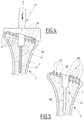
- FIG. 4 is a sectional view of the scapula and impacting device of FIG. 3 during impact;
- FIG. 5 is a sectional view of the scapula after impact and withdrawal of the impacting device
- FIG. 6 is a sectional view of the scapula, and of a shoulder implant fixed to the scapula;
- FIG. 7 is a perspective view of the scapula and shoulder implant of FIG. 6 .
- FIG. 1 shows a scapula S of a patient, the scapula S comprising a glenoid cavity G.
- the glenoid cavity G shows a damaged irregular surface which motivates the attachment of an implant.
- the scapula S comprises a cortical bone area C, which is the outer and hard bone portion of the scapula S.
- the scapula S also comprises a cancellous bone area Ca, which is the inner and soft bone portion of the scapula S.
- the cortical bone C and the cancellous bone Ca are represented on FIGS. 4 to 6 .
- FIG. 1 also represents a drilling guide 1 .
- the drilling guide 1 is patient specific and comprises a base plate 10 having an underside surface 10 a which is congruent to the glenoid cavity G.
- the drilling guide comprises a tube 12 for inserting drilling tools 3 and 4 , which are used for drilling holes in the scapula S.
- the tube 12 is centered on a central axis X.
- the tube 12 comprises a first section 12 a , whose diameter is adapted to receive a bit 30 of the drilling tool 3 and a stop element 41 of the drilling tool 4 .
- the tube comprises a second section 12 b which has a reduced diameter adapted for insertion of the bit 30 and prevents further insertion of the stop element 41 .
- the tube 12 comprises an axial edge 12 c which prevents insertion of a stop element 31 of the drilling tool 3 .
- the axial dimensions of the sections 12 a and 12 b along the axis X are predetermined on the basis of the depth of a post and a screw used to attach a shoulder implant to the scapula S, which are patient-specific and determined using medical imaging technologies.
- the scapula S is represented after drillings have been performed.
- the scapula S shows a first hole 100 , drilled by the drilling tool 4 , and a second hole 102 , which is coaxial and adjacent to the hole 100 , and which is drilled by the drilling tool 3 .
- the hole 100 is adapted for insertion of a screw, while the hole 102 is adapted for insertion of the post of the shoulder implant.
- the drilling guide 1 comprises a positioning notch 13 provided on the base plate 10 , and adapted to permit positioning of a reference marker.
- the reference marker is a hole 104 drilled in the scapula S.
- the reference marker can be a pin, or the like.
- the surgical instrumentation assembly also comprises an impacting device 20 having an underside surface 20 a which is congruent to the surface of the glenoid cavity G.
- the underside surface 20 a of the impacting device 20 is a negative surface of the glenoid cavity G.
- the impacting device 20 comprises a post 22 made of two sections whose diameters fit the diameters of the holes 100 and 102 .
- the impacting device 20 comprises protrusions 24 , formed by spikes in this example, which are provided on the underside surface and oriented along axis X towards the glenoid cavity G.
- the protrusions 24 form elongated elements protruding from the underside surface 20 a along axis X.
- the protrusions 24 are adapted to perforate the cortical bone C upon impact of the impacting device 20 against the scapula S by a one sided translation movement, along axis X, as shown by arrow F.
- the impacting device 20 provides a one sided translation movement with respect to the scapula S.
- the protrusions 24 are adapted to create channels 106 in the cortical bone C.
- the channels 106 extend towards the cancellous bone Ca.
- the shape and spatial distribution of the protrusions 24 is arranged according to different densities, thicknesses and lengths determined on the basis of the density and the thickness of the cortical bone C. Depending on the properties of the cortical bone C, which are determined using imaging, such as CT scans, the shape and distribution of protrusions 24 is determined so that the cortical bone C is properly perforated during impaction of the impacting device 20 .
- the length of the protrusions 24 can be comprised between 1 and 5 millimeters depending on the thickness of the cortical bone C.
- the thickness of the protrusions 24 can be comprised between 0.5 and 3 millimeters depending on the hardness or density of the cortical bone C.
- the density of the protrusions 24 can be comprised between 1 and 10 protrusions per square centimeter depending on the hardness or density of the cortical bone C.
- the protrusions 24 are arranged and shaped so that thinner and longer protrusions 24 are used where the cortical bone is thicker.
- the impacting device 20 comprises a notch 28 adapted to be aligned with the reference hole 104 provided on the glenoid cavity G.
- FIGS. 6 and 7 represent a glenoid shoulder implant 5 comprising a base plate 52 and an underside portion 54 which is made of a porous material.
- Said porous material may, for instance, a metallic material, a ceramic material or a polymer material, such as plasma spray, titanium trabecular structure, or acid or laser etched surface treatment.
- the shoulder prosthesis implant is patient specific and the underside portion 54 comprises an underside surface 54 a which is congruent with the surface of the glenoid cavity G.
- the implant 5 comprises a post 56 extending along axis X and is adapted to receive a screw 58 , which is inserted in the hole 100 to attach the implant 5 to the scapula S.
- the implant 5 comprises a hole 62 which runs through the base plate 52 and the underside portion 54 , and which receives the screw 58 .
- the porous material of the underside portion 54 facilitates bone growth induced by the channels 106 in the cortical bone C. As represented on FIG. 6 , cancellous bone Ca grows in the channels 106 inducing bone growth in the porosities of the underside portion 54 . Such bone growth improves the anchoring of the implant 5 in the scapula S.
- a non-shown articulation surface can be fixed to the base plate 52 , using non-shown screws which are inserted in holes 60 provided in the base plate 52 and the underside portion 54 .
- the holes 60 provide a guide for drilling the scapula S to create holes 108 for inserting the screws in the holes 60 and in the scapula S.
- the surgical shoulder repair method is implemented in the following manner.
- the characteristics of the scapula S of the patient are first determined using imaging technology.
- the shape of the glenoid cavity, the density, thickness and hardness of the cortical bone C, are used to design the drilling guide 1 , the underside surface 20 a of the impacting device 20 and the distribution and shape of the protrusions 24 , and the implant 5 , including the shape of the underside surface 54 a and the length of the post 56 .
- the glenoid cavity G is then prepared by removing, if necessary, remaining cartilage on the glenoid cavity G.
- the scapula S is then drilled using the drilling guide 1 .
- the position of the drilling guide 1 is referenced using the notch 13 .
- the glenoid cavity G is then impacted upon a one sided translational movement, using the impacting device 20 positioned using the notch 28 and guided during the translational movement by the post 22 , to perforate of the cortical bone C and create channels 106 towards the cancellous bone Ca.
- the patient specific implant 5 with its underside porous portion 54 and its patient specific underside surface 54 a is then attached to the scapula S using the screw 58 . Bone growth in the porosities of the underside portion 54 may be accelerated using bone growth factors. The non-shown articulation surface may then be attached to the implant 5 .
- the drilling guide 1 and the impacting device 20 may be disposed or recycled after completion of the surgical repair process.
Landscapes
- Health & Medical Sciences (AREA)
- Life Sciences & Earth Sciences (AREA)
- Orthopedic Medicine & Surgery (AREA)
- Animal Behavior & Ethology (AREA)
- General Health & Medical Sciences (AREA)
- Engineering & Computer Science (AREA)
- Biomedical Technology (AREA)
- Heart & Thoracic Surgery (AREA)
- Veterinary Medicine (AREA)
- Oral & Maxillofacial Surgery (AREA)
- Public Health (AREA)
- Surgery (AREA)
- Transplantation (AREA)
- Cardiology (AREA)
- Vascular Medicine (AREA)
- Dentistry (AREA)
- Nuclear Medicine, Radiotherapy & Molecular Imaging (AREA)
- Medical Informatics (AREA)
- Molecular Biology (AREA)
- Prostheses (AREA)
- Surgical Instruments (AREA)
- Physical Education & Sports Medicine (AREA)
Abstract
Description
-
- The protrusions of the impacting device are adapted to create channels in the cortical bone of the scapula, the channels extending towards the cancellous bone of the scapula.
- The protrusions have a distribution and a shape arranged according to different densities, thicknesses and lengths determined on the basis of the density and thickness of the cortical bone of the glenoid cavity of the scapula of the patient.
- The impacting device comprises a post adapted to be inserted into a positioning hole drilled in the scapula.
- The assembly comprises a patient specific drilling guide for drilling holes for inserting a post of a shoulder implant and a screw for attaching the shoulder implant.
- The drilling guide comprises a notch for positioning a reference marker on the scapula.
- The impacting device comprises a notch for alignment with a reference marker.
- The protrusions are spikes.
-
- a) providing a patient specific impacting device having an underside surface congruent with the surface of the glenoid cavity of the scapula of the patient, said underside surface being provided with protrusions adapted to perforate the cortical bone of the scapula upon impact of the impacting device by a one-sided translation movement;
- b) impacting the glenoid cavity to create channels through the cortical bone of the scapula;
- c) providing a patient specific shoulder implant having an underside portion made of a porous material adapted to facilitate bone growth induced by the channels created through the cortical bone.
-
- The method comprises prior to step a), further steps consisting in:
- d) providing a patient-specific drilling guide having an underside surface congruent with the surface of the glenoid cavity of the scapula of a patient;
- e) drilling holes for a post of the shoulder implant and a screw for attachment of the shoulder implant.
- The lengths of the post and screw are pre-determined.
- The method comprises a further step consisting in providing a notch in the drilling guide for placing a reference marker on the scapula.
- The distribution and shape of the protrusions are determined by imaging technology on the basis of the bone characteristics of the glenoid cavity of the scapula of the patient.
- The density, the thickness and the length of the protrusions are determined depending on the density and thickness of the cortical bone of the glenoid cavity measured by CT scans.
- Thinner and longer protrusions are used where the cortical bone is thicker.
- The method comprises a step consisting in aligning the impacting device with a reference marker provided on the scapula.
- The method comprises a step consisting in providing a notch in the impacting device for alignment with the reference marker.
- The method comprises prior to step a), further steps consisting in:
Claims (18)
Priority Applications (2)
| Application Number | Priority Date | Filing Date | Title |
|---|---|---|---|
| US15/454,259 US11090161B2 (en) | 2016-03-25 | 2017-03-09 | Surgical instrumentation assembly, set and surgical shoulder repair method |
| US17/378,910 US11918473B2 (en) | 2016-03-25 | 2021-07-19 | Surgical instrumentation assembly, set and surgical shoulder repair method |
Applications Claiming Priority (2)
| Application Number | Priority Date | Filing Date | Title |
|---|---|---|---|
| US201662313470P | 2016-03-25 | 2016-03-25 | |
| US15/454,259 US11090161B2 (en) | 2016-03-25 | 2017-03-09 | Surgical instrumentation assembly, set and surgical shoulder repair method |
Related Child Applications (1)
| Application Number | Title | Priority Date | Filing Date |
|---|---|---|---|
| US17/378,910 Division US11918473B2 (en) | 2016-03-25 | 2021-07-19 | Surgical instrumentation assembly, set and surgical shoulder repair method |
Publications (2)
| Publication Number | Publication Date |
|---|---|
| US20170273801A1 US20170273801A1 (en) | 2017-09-28 |
| US11090161B2 true US11090161B2 (en) | 2021-08-17 |
Family
ID=59896831
Family Applications (2)
| Application Number | Title | Priority Date | Filing Date |
|---|---|---|---|
| US15/454,259 Active US11090161B2 (en) | 2016-03-25 | 2017-03-09 | Surgical instrumentation assembly, set and surgical shoulder repair method |
| US17/378,910 Active 2037-09-10 US11918473B2 (en) | 2016-03-25 | 2021-07-19 | Surgical instrumentation assembly, set and surgical shoulder repair method |
Family Applications After (1)
| Application Number | Title | Priority Date | Filing Date |
|---|---|---|---|
| US17/378,910 Active 2037-09-10 US11918473B2 (en) | 2016-03-25 | 2021-07-19 | Surgical instrumentation assembly, set and surgical shoulder repair method |
Country Status (4)
| Country | Link |
|---|---|
| US (2) | US11090161B2 (en) |
| EP (1) | EP3432812B1 (en) |
| CA (1) | CA3018789A1 (en) |
| WO (1) | WO2017165346A1 (en) |
Cited By (4)
| Publication number | Priority date | Publication date | Assignee | Title |
|---|---|---|---|---|
| US20210338435A1 (en) * | 2016-03-25 | 2021-11-04 | Howmedica Osteonics Corp. | Surgical instrumentation assembly, set and surgical shoulder repair method |
| US12070272B2 (en) | 2013-10-10 | 2024-08-27 | Stryker European Operations Limited | Methods, systems and devices for pre-operatively planned shoulder surgery guides and implants |
| US12097129B2 (en) | 2013-11-13 | 2024-09-24 | Tornier Sas | Shoulder patient specific instrument |
| US12133688B2 (en) | 2013-11-08 | 2024-11-05 | Stryker European Operations Limited | Methods, systems and devices for pre-operatively planned adaptive glenoid implants |
Families Citing this family (22)
| Publication number | Priority date | Publication date | Assignee | Title |
|---|---|---|---|---|
| FR2932674B1 (en) | 2008-06-20 | 2011-11-18 | Tornier Sa | METHOD FOR MODELING A GLENOIDAL SURFACE OF AN OMOPLATE, DEVICE FOR IMPLANTING A GLENOIDAL COMPONENT OF A SHOULDER PROSTHESIS, AND METHOD FOR MANUFACTURING SUCH COMPOUND |
| FR2955247B1 (en) | 2010-01-21 | 2013-04-26 | Tornier Sa | GLENOIDAL COMPONENT OF SHOULDER PROSTHESIS |
| FR2971144A1 (en) | 2011-02-08 | 2012-08-10 | Tornier Sa | GLENOIDAL IMPLANT FOR SHOULDER PROSTHESIS AND SURGICAL KIT |
| DE102013112497A1 (en) * | 2013-11-13 | 2015-05-13 | Aesculap Ag | Medical Instrument |
| EP3777777B1 (en) | 2014-01-03 | 2023-04-05 | Howmedica Osteonics Corp. | Glenoid implant for a shoulder prosthesis |
| US10722374B2 (en) | 2015-05-05 | 2020-07-28 | Tornier, Inc. | Convertible glenoid implant |
| WO2017105815A1 (en) | 2015-12-16 | 2017-06-22 | Tornier, Inc. | Patient specific instruments and methods for joint prosthesis |
| EP3222253B1 (en) | 2016-03-25 | 2020-03-18 | Tornier | Methods of forming a joint prosthesis component, of forming a bone press component and a bone press |
| WO2019014278A1 (en) | 2017-07-11 | 2019-01-17 | Tornier, Inc. | Guides and instruments for improving accuracy of glenoid implant placement |
| WO2019014281A1 (en) | 2017-07-11 | 2019-01-17 | Tornier, Inc. | Patient specific humeral cutting guides |
| EP4497417A3 (en) | 2017-10-16 | 2025-04-30 | Stryker European Operations Limited | Shoulder implants |
| WO2019133905A1 (en) | 2017-12-29 | 2019-07-04 | Tornier, Inc. | Patient specific humeral implant components |
| CA3107923A1 (en) | 2018-07-27 | 2020-01-30 | Ignite Orthopedics Llc | Implants, systems and methods of using the same |
| US12295853B2 (en) | 2018-07-27 | 2025-05-13 | Depuy Ireland Unlimited Company | Implants, systems and methods of using the same |
| AU2020276186C1 (en) | 2019-05-13 | 2022-07-21 | Howmedica Osteonics Corp. | Glenoid baseplate and implant assemblies |
| WO2021030146A1 (en) | 2019-08-09 | 2021-02-18 | Tornier, Inc. | Apparatuses and methods for implanting glenoid prostheses |
| EP4125732A1 (en) | 2020-04-01 | 2023-02-08 | Arthrex, Inc. | Systems and methods of forming orthopaedic implants including printed augments |
| AU2021358039A1 (en) | 2020-10-09 | 2023-03-30 | Arthrex, Inc. | Convertible orthopaedic implant systems and methods |
| US12508130B2 (en) | 2021-02-26 | 2025-12-30 | Howmedica Osteonics Corp. | Glenoid implant components and instruments therefor |
| US11737883B2 (en) | 2021-03-02 | 2023-08-29 | Arthrex, Inc. | Orthopaedic implants including breakaway fastener |
| US11819415B2 (en) * | 2021-04-02 | 2023-11-21 | Arthrex, Inc. | Orthopaedic implant systems including internal networks and methods of repair |
| CN117279596A (en) | 2021-04-27 | 2023-12-22 | 阿瑟雷克斯股份有限公司 | Orthopedic implant systems incorporating transfer features and methods for planning transfer |
Citations (15)
| Publication number | Priority date | Publication date | Assignee | Title |
|---|---|---|---|---|
| US5885298A (en) * | 1994-02-23 | 1999-03-23 | Biomet, Inc. | Patellar clamp and reamer with adjustable stop |
| US5961535A (en) | 1996-10-17 | 1999-10-05 | Rosenberg; Thomas D. | Instrument and method for surgical stimulation of connective tissue |
| US20050043805A1 (en) * | 2003-08-11 | 2005-02-24 | Chudik Steven C. | Devices and methods used for shoulder replacement |
| US20050060039A1 (en) | 2003-09-11 | 2005-03-17 | Jean-Maxwell Cyprien | Shoulder glenoid prosthesis with method and tools for implanting it |
| US20060195194A1 (en) * | 2005-02-25 | 2006-08-31 | Gunther Stephen B | Shoulder implant for glenoid replacement and methods of use thereof |
| US20110166578A1 (en) * | 2006-02-27 | 2011-07-07 | Biomet Manufacturing Corp. | Alignment guides with patient-specific anchoring elements |
| US20120046663A1 (en) | 2010-08-17 | 2012-02-23 | Warsaw Orthopedic, Inc. | Bone scoring device |
| US20130006250A1 (en) * | 2011-07-01 | 2013-01-03 | Biomet Manufacturing Corp. | Patient-specific bone-cutting guidance instruments and methods |
| US20140107715A1 (en) | 2011-10-27 | 2014-04-17 | Biomet Manufacturing Corporation | Patient Specific Glenoid Guide |
| US20140257499A1 (en) | 2013-03-08 | 2014-09-11 | Biomet Manufacturing, Llc | Modular Glenoid Base plate With Augments |
| US20150150688A1 (en) | 2013-12-03 | 2015-06-04 | Biomet Manufacturing, Llc | Patient-Specific Glenoid Implant |
| US9248022B2 (en) | 2012-03-27 | 2016-02-02 | DePuy Synthes Products, Inc. | Method of implanting a glenoid defect-filling component |
| US20160045323A1 (en) | 2014-08-14 | 2016-02-18 | Biomet Manufacturing, Llc | Glenoid implant |
| US20160374693A1 (en) | 2015-06-23 | 2016-12-29 | The Trustees Of Dartmouth College | Method of enhancing interdigitation of bone cement to bone for attachment of prosthesis to bone during arthroplasty |
| US9700325B2 (en) * | 2013-03-12 | 2017-07-11 | Biomet Manufacturing, Llc | Multi-point fit for patient specific guide |
Family Cites Families (18)
| Publication number | Priority date | Publication date | Assignee | Title |
|---|---|---|---|---|
| US4659331A (en) * | 1983-11-28 | 1987-04-21 | Regents Of University Of Michigan | Prosthesis interface surface and method of implanting |
| US5098383A (en) * | 1990-02-08 | 1992-03-24 | Artifax Ltd. | Device for orienting appliances, prostheses, and instrumentation in medical procedures and methods of making same |
| US5895178A (en) * | 1998-03-31 | 1999-04-20 | Young; Ralph C. | Large hole cutter |
| US6059789A (en) * | 1998-06-22 | 2000-05-09 | Xomed Surgical Products, Inc. | Drill guide for creating a tunnel in bone for fixating soft tissue to the bone and kit and method for fixating soft tissue to bone |
| GB0313445D0 (en) * | 2003-06-11 | 2003-07-16 | Midland Medical Technologies L | Hip resurfacing |
| EP1588668B1 (en) * | 2004-04-20 | 2008-12-10 | Finsbury (Development) Limited | Alignment guide for use in femoral head surgery |
| US7766913B2 (en) * | 2004-12-07 | 2010-08-03 | Depuy Products, Inc. | Bone shaping instrument and method for using the same |
| WO2007054553A1 (en) * | 2005-11-09 | 2007-05-18 | Zimmer Gmbh | Implant |
| US8298237B2 (en) * | 2006-06-09 | 2012-10-30 | Biomet Manufacturing Corp. | Patient-specific alignment guide for multiple incisions |
| US8425614B2 (en) * | 2006-03-20 | 2013-04-23 | Biomet Manufacturing Corp. | Modular center pegged glenoid |
| US8066511B2 (en) * | 2008-03-18 | 2011-11-29 | Woehrle Peter | Asymmetrical dental implant |
| US8702717B2 (en) * | 2009-07-31 | 2014-04-22 | Zimmer Gmbh | Glenoid alignment tool |
| GB201007166D0 (en) * | 2010-04-29 | 2010-06-09 | Finsbury Dev Ltd | Prosthesis |
| RU2013109817A (en) * | 2010-08-13 | 2014-09-20 | Смит Энд Нефью, Инк. | SURGICAL PATTERN |
| US10034777B2 (en) * | 2012-03-30 | 2018-07-31 | DePuy Synthes Products, Inc. | Implant insertion tool for use in a surgical procedure to implant a stemless humeral component |
| US9615839B2 (en) * | 2014-03-18 | 2017-04-11 | Howmedica Osteonics Corp. | Shape-fit glenoid reaming systems and methods |
| US10485670B2 (en) * | 2015-08-14 | 2019-11-26 | Gerhard E. Maale | Glenoid fossa prosthesis |
| US11090161B2 (en) * | 2016-03-25 | 2021-08-17 | Howmedica Osteonics Corp. | Surgical instrumentation assembly, set and surgical shoulder repair method |
-
2017
- 2017-03-09 US US15/454,259 patent/US11090161B2/en active Active
- 2017-03-21 CA CA3018789A patent/CA3018789A1/en active Pending
- 2017-03-21 EP EP17770941.7A patent/EP3432812B1/en active Active
- 2017-03-21 WO PCT/US2017/023305 patent/WO2017165346A1/en not_active Ceased
-
2021
- 2021-07-19 US US17/378,910 patent/US11918473B2/en active Active
Patent Citations (16)
| Publication number | Priority date | Publication date | Assignee | Title |
|---|---|---|---|---|
| US5885298A (en) * | 1994-02-23 | 1999-03-23 | Biomet, Inc. | Patellar clamp and reamer with adjustable stop |
| US5961535A (en) | 1996-10-17 | 1999-10-05 | Rosenberg; Thomas D. | Instrument and method for surgical stimulation of connective tissue |
| US20050043805A1 (en) * | 2003-08-11 | 2005-02-24 | Chudik Steven C. | Devices and methods used for shoulder replacement |
| US20050060039A1 (en) | 2003-09-11 | 2005-03-17 | Jean-Maxwell Cyprien | Shoulder glenoid prosthesis with method and tools for implanting it |
| US20060195194A1 (en) * | 2005-02-25 | 2006-08-31 | Gunther Stephen B | Shoulder implant for glenoid replacement and methods of use thereof |
| US20110166578A1 (en) * | 2006-02-27 | 2011-07-07 | Biomet Manufacturing Corp. | Alignment guides with patient-specific anchoring elements |
| US20120046663A1 (en) | 2010-08-17 | 2012-02-23 | Warsaw Orthopedic, Inc. | Bone scoring device |
| US8764760B2 (en) | 2011-07-01 | 2014-07-01 | Biomet Manufacturing, Llc | Patient-specific bone-cutting guidance instruments and methods |
| US20130006250A1 (en) * | 2011-07-01 | 2013-01-03 | Biomet Manufacturing Corp. | Patient-specific bone-cutting guidance instruments and methods |
| US20140107715A1 (en) | 2011-10-27 | 2014-04-17 | Biomet Manufacturing Corporation | Patient Specific Glenoid Guide |
| US9248022B2 (en) | 2012-03-27 | 2016-02-02 | DePuy Synthes Products, Inc. | Method of implanting a glenoid defect-filling component |
| US20140257499A1 (en) | 2013-03-08 | 2014-09-11 | Biomet Manufacturing, Llc | Modular Glenoid Base plate With Augments |
| US9700325B2 (en) * | 2013-03-12 | 2017-07-11 | Biomet Manufacturing, Llc | Multi-point fit for patient specific guide |
| US20150150688A1 (en) | 2013-12-03 | 2015-06-04 | Biomet Manufacturing, Llc | Patient-Specific Glenoid Implant |
| US20160045323A1 (en) | 2014-08-14 | 2016-02-18 | Biomet Manufacturing, Llc | Glenoid implant |
| US20160374693A1 (en) | 2015-06-23 | 2016-12-29 | The Trustees Of Dartmouth College | Method of enhancing interdigitation of bone cement to bone for attachment of prosthesis to bone during arthroplasty |
Non-Patent Citations (1)
| Title |
|---|
| Search Report and Written Opinion issued in PCT/US2017/02305 dated Jun. 30, 2017 (12 pages). |
Cited By (8)
| Publication number | Priority date | Publication date | Assignee | Title |
|---|---|---|---|---|
| US12070272B2 (en) | 2013-10-10 | 2024-08-27 | Stryker European Operations Limited | Methods, systems and devices for pre-operatively planned shoulder surgery guides and implants |
| US12133691B2 (en) | 2013-10-10 | 2024-11-05 | Stryker European Operations Limited | Methods, systems and devices for pre-operatively planned shoulder surgery guides and implants |
| US12137982B2 (en) | 2013-10-10 | 2024-11-12 | Stryker European Operations Limited | Methods, systems and devices for pre-operatively planned shoulder surgery guides and implants |
| US12133688B2 (en) | 2013-11-08 | 2024-11-05 | Stryker European Operations Limited | Methods, systems and devices for pre-operatively planned adaptive glenoid implants |
| US12178517B2 (en) | 2013-11-08 | 2024-12-31 | Stryker European Operations Limited | Methods, systems and devices for pre-operatively planned adaptive glenoid implants |
| US12097129B2 (en) | 2013-11-13 | 2024-09-24 | Tornier Sas | Shoulder patient specific instrument |
| US20210338435A1 (en) * | 2016-03-25 | 2021-11-04 | Howmedica Osteonics Corp. | Surgical instrumentation assembly, set and surgical shoulder repair method |
| US11918473B2 (en) * | 2016-03-25 | 2024-03-05 | Howmedica Osteonics Corp. | Surgical instrumentation assembly, set and surgical shoulder repair method |
Also Published As
| Publication number | Publication date |
|---|---|
| EP3432812A4 (en) | 2019-11-27 |
| US11918473B2 (en) | 2024-03-05 |
| EP3432812B1 (en) | 2023-10-11 |
| EP3432812A1 (en) | 2019-01-30 |
| US20210338435A1 (en) | 2021-11-04 |
| CA3018789A1 (en) | 2017-09-28 |
| US20170273801A1 (en) | 2017-09-28 |
| WO2017165346A1 (en) | 2017-09-28 |
Similar Documents
| Publication | Publication Date | Title |
|---|---|---|
| US11918473B2 (en) | Surgical instrumentation assembly, set and surgical shoulder repair method | |
| JP6947802B2 (en) | Patient-specific augmented glenoid system | |
| KR100541994B1 (en) | Device for producing endochondral and osteochondral drilled holes | |
| ES2674693T3 (en) | A surgical instrument to implant a humeral component | |
| EP2340787B1 (en) | Reciprocating rasp surgical instrument | |
| KR102876356B1 (en) | Bone-preserving humeral implant and related methods | |
| CN102596103B (en) | Cranial implant and component set including same | |
| JP6466972B2 (en) | Patient-specific glenoid depth control | |
| US20100241124A1 (en) | Soft Tissue Manipulator Assembly | |
| EP2072016A1 (en) | Bone plate instrument and method | |
| EP3335675A1 (en) | Humeral implant and set of instruments for surgical shoulder articulation replacement | |
| CN104039249A (en) | Implant specific drill bit | |
| US20050069835A1 (en) | System for fixing a dental implant | |
| US20100016860A1 (en) | Depth gauge cup impactor | |
| EP3023067A1 (en) | Strut plate and cabling system | |
| CN111194188B (en) | Easily-started hollow bone screw | |
| US20150216578A1 (en) | Drill Alignment Device, Method for Manufacturing the Drill Alignment Device and a Method for Removing Bone Cement | |
| US11696773B2 (en) | Guided punch for talar augments | |
| CA2609171A1 (en) | Modular template for drilling holes and method of making same | |
| CN102226510A (en) | Partial implant for articular surfaces and method of installation |
Legal Events
| Date | Code | Title | Description |
|---|---|---|---|
| AS | Assignment |
Owner name: TORNIER, INC., MINNESOTA Free format text: ASSIGNMENT OF ASSIGNORS INTEREST;ASSIGNOR:HODOREK, BRIAN;REEL/FRAME:041529/0480 Effective date: 20170110 |
|
| AS | Assignment |
Owner name: MIDCAP FUNDING IV TRUST, AS AGENT, MARYLAND Free format text: SECURITY INTEREST;ASSIGNORS:WRIGHT MEDICAL GROUP N.V.;WRIGHT MEDICAL GROUP, INC.;BIOMIMETIC THERAPEUTICS CANADA, INC.;AND OTHERS;REEL/FRAME:046291/0001 Effective date: 20180507 |
|
| STPP | Information on status: patent application and granting procedure in general |
Free format text: FINAL REJECTION MAILED |
|
| STPP | Information on status: patent application and granting procedure in general |
Free format text: DOCKETED NEW CASE - READY FOR EXAMINATION |
|
| STPP | Information on status: patent application and granting procedure in general |
Free format text: NON FINAL ACTION MAILED |
|
| STPP | Information on status: patent application and granting procedure in general |
Free format text: RESPONSE TO NON-FINAL OFFICE ACTION ENTERED AND FORWARDED TO EXAMINER |
|
| STPP | Information on status: patent application and granting procedure in general |
Free format text: NON FINAL ACTION MAILED |
|
| AS | Assignment |
Owner name: ORTHOHELIX SURGICAL DESIGNS, INC., MINNESOTA Free format text: RELEASE BY SECURED PARTY;ASSIGNOR:MIDCAP FUNDING IV TRUST;REEL/FRAME:054480/0001 Effective date: 20201112 Owner name: TORNIER US HOLDINGS, INC., MINNESOTA Free format text: RELEASE BY SECURED PARTY;ASSIGNOR:MIDCAP FUNDING IV TRUST;REEL/FRAME:054480/0001 Effective date: 20201112 Owner name: BIOMIMETIC THERAPEUTICS CANADA, INC., TENNESSEE Free format text: RELEASE BY SECURED PARTY;ASSIGNOR:MIDCAP FUNDING IV TRUST;REEL/FRAME:054480/0001 Effective date: 20201112 Owner name: WRIGHT MEDICAL GROUP INTELLECTUAL PROPERTY, INC., TENNESSEE Free format text: RELEASE BY SECURED PARTY;ASSIGNOR:MIDCAP FUNDING IV TRUST;REEL/FRAME:054480/0001 Effective date: 20201112 Owner name: WHITE BOX ORTHOPEDICS, LLC, TENNESSEE Free format text: RELEASE BY SECURED PARTY;ASSIGNOR:MIDCAP FUNDING IV TRUST;REEL/FRAME:054480/0001 Effective date: 20201112 Owner name: ORTHOPRO, L.L.C., TENNESSEE Free format text: RELEASE BY SECURED PARTY;ASSIGNOR:MIDCAP FUNDING IV TRUST;REEL/FRAME:054480/0001 Effective date: 20201112 Owner name: WRIGHT MEDICAL TECHNOLOGY, INC., TENNESSEE Free format text: RELEASE BY SECURED PARTY;ASSIGNOR:MIDCAP FUNDING IV TRUST;REEL/FRAME:054480/0001 Effective date: 20201112 Owner name: BIOMIMETIC THERAPEUTICS USA, INC., TENNESSEE Free format text: RELEASE BY SECURED PARTY;ASSIGNOR:MIDCAP FUNDING IV TRUST;REEL/FRAME:054480/0001 Effective date: 20201112 Owner name: WRIGHT MEDICAL GROUP, INC., TENNESSEE Free format text: RELEASE BY SECURED PARTY;ASSIGNOR:MIDCAP FUNDING IV TRUST;REEL/FRAME:054480/0001 Effective date: 20201112 Owner name: BIOMIMETIC THERAPEUTICS, LLC, TENNESSEE Free format text: RELEASE BY SECURED PARTY;ASSIGNOR:MIDCAP FUNDING IV TRUST;REEL/FRAME:054480/0001 Effective date: 20201112 Owner name: TORNIER, INC., MINNESOTA Free format text: RELEASE BY SECURED PARTY;ASSIGNOR:MIDCAP FUNDING IV TRUST;REEL/FRAME:054480/0001 Effective date: 20201112 Owner name: SOLANA SURGICAL, LLC, TENNESSEE Free format text: RELEASE BY SECURED PARTY;ASSIGNOR:MIDCAP FUNDING IV TRUST;REEL/FRAME:054480/0001 Effective date: 20201112 Owner name: INBONE TECHNOLOGIES, INC., TENNESSEE Free format text: RELEASE BY SECURED PARTY;ASSIGNOR:MIDCAP FUNDING IV TRUST;REEL/FRAME:054480/0001 Effective date: 20201112 Owner name: TROOPER HOLDINGS INC., MINNESOTA Free format text: RELEASE BY SECURED PARTY;ASSIGNOR:MIDCAP FUNDING IV TRUST;REEL/FRAME:054480/0001 Effective date: 20201112 Owner name: WRIGHT MEDICAL CAPITAL, INC., TENNESSEE Free format text: RELEASE BY SECURED PARTY;ASSIGNOR:MIDCAP FUNDING IV TRUST;REEL/FRAME:054480/0001 Effective date: 20201112 Owner name: WRIGHT MEDICAL GROUP N.V., NETHERLANDS Free format text: RELEASE BY SECURED PARTY;ASSIGNOR:MIDCAP FUNDING IV TRUST;REEL/FRAME:054480/0001 Effective date: 20201112 |
|
| STPP | Information on status: patent application and granting procedure in general |
Free format text: RESPONSE TO NON-FINAL OFFICE ACTION ENTERED AND FORWARDED TO EXAMINER |
|
| STPP | Information on status: patent application and granting procedure in general |
Free format text: NOTICE OF ALLOWANCE MAILED -- APPLICATION RECEIVED IN OFFICE OF PUBLICATIONS |
|
| AS | Assignment |
Owner name: HOWMEDICA OSTEONICS CORP., NEW JERSEY Free format text: ASSIGNMENT OF ASSIGNORS INTEREST;ASSIGNOR:TORNIER, INC.;REEL/FRAME:056439/0435 Effective date: 20210521 |
|
| STPP | Information on status: patent application and granting procedure in general |
Free format text: PUBLICATIONS -- ISSUE FEE PAYMENT RECEIVED |
|
| STPP | Information on status: patent application and granting procedure in general |
Free format text: PUBLICATIONS -- ISSUE FEE PAYMENT VERIFIED |
|
| STCF | Information on status: patent grant |
Free format text: PATENTED CASE |
|
| MAFP | Maintenance fee payment |
Free format text: PAYMENT OF MAINTENANCE FEE, 4TH YEAR, LARGE ENTITY (ORIGINAL EVENT CODE: M1551); ENTITY STATUS OF PATENT OWNER: LARGE ENTITY Year of fee payment: 4 |