EP3697196B1 - Schneidelement mit ziehendem schnitt - Google Patents
Schneidelement mit ziehendem schnitt Download PDFInfo
- Publication number
- EP3697196B1 EP3697196B1 EP18793375.9A EP18793375A EP3697196B1 EP 3697196 B1 EP3697196 B1 EP 3697196B1 EP 18793375 A EP18793375 A EP 18793375A EP 3697196 B1 EP3697196 B1 EP 3697196B1
- Authority
- EP
- European Patent Office
- Prior art keywords
- guiding surface
- cutting element
- guide surface
- implement according
- blade
- Prior art date
- Legal status (The legal status is an assumption and is not a legal conclusion. Google has not performed a legal analysis and makes no representation as to the accuracy of the status listed.)
- Active
Links
- 239000000463 material Substances 0.000 claims description 9
- 238000003306 harvesting Methods 0.000 claims description 6
- 230000007704 transition Effects 0.000 claims description 5
- 240000008042 Zea mays Species 0.000 description 12
- 235000002017 Zea mays subsp mays Nutrition 0.000 description 9
- 235000005824 Zea mays ssp. parviglumis Nutrition 0.000 description 5
- 235000005822 corn Nutrition 0.000 description 5
- 239000010902 straw Substances 0.000 description 5
- 239000002028 Biomass Substances 0.000 description 4
- 241000196324 Embryophyta Species 0.000 description 4
- 235000016383 Zea mays subsp huehuetenangensis Nutrition 0.000 description 4
- 230000000694 effects Effects 0.000 description 4
- 235000009973 maize Nutrition 0.000 description 4
- 239000002689 soil Substances 0.000 description 3
- 239000000428 dust Substances 0.000 description 2
- 244000005700 microbiome Species 0.000 description 2
- 235000013399 edible fruits Nutrition 0.000 description 1
- 239000004459 forage Substances 0.000 description 1
- 238000007689 inspection Methods 0.000 description 1
- 238000012805 post-processing Methods 0.000 description 1
- 239000004460 silage Substances 0.000 description 1
Images


Classifications
-
- A—HUMAN NECESSITIES
- A01—AGRICULTURE; FORESTRY; ANIMAL HUSBANDRY; HUNTING; TRAPPING; FISHING
- A01D—HARVESTING; MOWING
- A01D34/00—Mowers; Mowing apparatus of harvesters
- A01D34/835—Mowers; Mowing apparatus of harvesters specially adapted for particular purposes
- A01D34/8355—Mowers; Mowing apparatus of harvesters specially adapted for particular purposes for cutting up or crushing remaining standing stalks, e.g. stubble
-
- A—HUMAN NECESSITIES
- A01—AGRICULTURE; FORESTRY; ANIMAL HUSBANDRY; HUNTING; TRAPPING; FISHING
- A01D—HARVESTING; MOWING
- A01D34/00—Mowers; Mowing apparatus of harvesters
- A01D34/01—Mowers; Mowing apparatus of harvesters characterised by features relating to the type of cutting apparatus
- A01D34/412—Mowers; Mowing apparatus of harvesters characterised by features relating to the type of cutting apparatus having rotating cutters
- A01D34/63—Mowers; Mowing apparatus of harvesters characterised by features relating to the type of cutting apparatus having rotating cutters having cutters rotating about a vertical axis
- A01D34/73—Cutting apparatus
- A01D34/736—Flail type
-
- A—HUMAN NECESSITIES
- A01—AGRICULTURE; FORESTRY; ANIMAL HUSBANDRY; HUNTING; TRAPPING; FISHING
- A01D—HARVESTING; MOWING
- A01D45/00—Harvesting of standing crops
- A01D45/02—Harvesting of standing crops of maize, i.e. kernel harvesting
- A01D45/021—Cornheaders
Definitions
- the present invention relates to an attachment for harvesting stalky stalks with a conveying device and a device for cutting stems, which is arranged in a plane below the conveying device and which has at least one cutting element rotating in a horizontal or at least approximately horizontal plane.
- a generic attachment is from the font DE 10 2015 115 100 A1 known in the form of a corn picker.
- a stalk of the stalks - such as a maize plant - runs into this attachment, the stalk is torn down by stalking rollers and the fruit stand, such as a corn cob of a maize plant, is separated from the maize stalk by the picking plates of the picking device.
- the corn cobs separated from the stalk are fed to a threshing device by a conveying device.
- the remaining corn stalk is transported further down by the stalking rollers, it can also be cut or trimmed.
- a stalk that is torn down is cut below the stalking rollers by chopping knives rotating at least approximately in a horizontal plane, which are arranged in the area of the stalking rollers.
- the rotating chopping knives cut the stalk pieces that have been transported down by the stalking rollers into even shorter stalk pieces, which are then thrown onto the field.
- the stalk pieces can then rot there.
- the rotating cutting elements are intended to split open the stubble and distribute the straw from the cut stalks on the ground.
- the rotating chopping knives not only cut the stalk pieces torn down by the stalking rollers, but also cut the protruding ends of the stubble of the maize plants that are still in the field after the stalks have been cut.
- An example of this way of working is found in Scripture DE 102 50 302 B4 .
- the remaining stubble is no longer spliced and pressed into the ground by the tires of the harvesting machine or other vehicles in the field, where it is very difficult for microorganisms to decompose them.
- a separate post-processing of stubble is necessary, in which the stubble has to be damaged after harvest so that it has rotted sufficiently before the next crop is sown. This requires additional work and the additional drive over the field compacts the soil unnecessarily.
- the cutting element has a guide surface on its outer edge which extends downward from the plane of the blade, the guide surface being inclined inwardly by an angle of incidence in the direction of rotation of the cutting element.
- the guide surface conveys the air, the biomass and other spatial bodies that are captured by the guide surface towards the axis of rotation of the rotating cutting element, that is to say inward.
- this together with the lateral guide surface forms a kind of bell or cage within its enveloping circle, in the interior of which the air, the biomass as well as other spatial bodies that have reached the effective area of the guide surface are mixed with one another.
- the bell or the cage are quasi closed upwards and to the side by the cutting element rotating at high speed with the guide surface extending downwards.
- the cutting elements are usually held in a central holder which is designed to be closed at the top.
- the air conveyed inward by the rotating guide surfaces, the biomass and the other spatial bodies that have been conveyed inward by the guide surface of a cutting element can therefore not escape upwards from the center of the interior.
- the material in the bell or cage can therefore only get out of the interior space downwards.
- the length of the guide surface is designed for the forward speed with which the harvesting machine, which carries the attachment, usually drives into the crop, as well as the rotational speed with which the cutting elements rotate.
- the length of the guide surface should be sufficient for the given forward speed and rotation speed to adequately fray and splice the stubble.
- the cut straw and other spatial bodies are carried along by the downward escaping air flow generated by the rotating guide surfaces and pressed onto the arable soil between the stubble.
- This also reduces the overpressure from the air that has accumulated inside the bell with the air flow downwards. In this way, the chopped straw is distributed more evenly on the arable land. Less material flies around in an uncontrolled manner in the working area of the header, so that the operation of the header becomes safer overall.
- a rotating cutting element as a kind of bell or cage is stronger the faster and / or the more cutting elements with guide surfaces rotate around a common axis of rotation.
- the generation of dust is significantly reduced. Due to the downward wind from the chopping device, dust-laden air is carried along by the crop flow and blown onto the arable soil together with the chopped plant residues.
- the guide surface on the rotating cutting element is not only advantageous for distributing the straw on the harvested area, it splits and smashes its structure when it hits a stubble and frays it far below the level of the blade, which, according to the state of the art, is the blade no longer would be attainable.
- the stubble After contact with the guide surface, the stubble is more easily accessible to microorganisms, which promotes rotting of the stubble.
- a single stubble can be hit several times by a guiding surface when a harvesting machine passes over it, whereby a stubble is spliced and smashed even better. There is no longer any need to rework the stubble in a further operation in the field.
- the transition from the blade plane to the guide surface runs in a rounded arc.
- a connection of the guide surface in a rounded arc is able to absorb higher force peaks than a sharp edge in the transition area. In this way, the cutting element is more resistant to contact with foreign bodies.
- the guide surface is positioned at an angle of more than 15 ° to the vertical, pointing inward on the leading edge of the blade.
- the pronounced inclination of the guide surface in relation to the direction of rotation of the cutting element results in a sufficiently large conveying and fanning effect of the guide surface.
- the air-conveying effect of the guide surface which has a considerable influence on the crop flow and the dropping of the stalk pieces on the field, is advantageous in the proposed design.
- the guide surface has an obliquely running edge on its end face pointing in the direction of rotation, which edge extends from the leading edge of the blade in the upper area falls backwards against the direction of rotation. Due to the sloping edge, the face of the guide surface does not collide with its entire surface butt against the outside of a stubble, but can increasingly move into the material of the stubble in the manner of a pulling cut without causing excessive force peaks.
- the lower edge of the guide surface slopes down from the front to the rear in relation to the plane of the blade, counter to the direction of rotation. Due to the sloping shape, the guide surface can slide onto the ground or the foreign body in the direction of rotation from front to back in the event of ground or foreign body contact. The cutting element blade is thereby lifted upwards during the rotational movement. This reduces wear and tear and the risk of breakage. As a result, the cutting element can be guided very close to the field floor by adjusting the height of the attachment. The stubble is caught by the guide surfaces very close to the ground and disintegrated.
- the guide surface has the greatest vertical extent in its rear third. Since stubble hit move downwards and to the side after initial contact with the guide surface, the rear parts of the guide surface opposite to the direction of rotation would have no or only insignificant contact with the crop if the guide surface did not extend further down in this area than in the part of the guide surface which, viewed in the direction of rotation, is formed further forward. The wear and In this way, the work performance of the control surface is better distributed over the entire area of the control surface.
- the angle of incidence of the guide surface to the blade plane in the radial direction from the pivot axis of the cutting element and in the vertical direction to the bottom is 80 ° to 100 °. If the angle of attack is exactly or approximately 90 °, the guide surface functions well.
- the end face and / or the lower edge of the guide surface have a material hardening with respect to the rest of the material of the guide surface. Since these areas of the guide surface are subject to particular stress and high wear, appropriate material hardening is advantageous.
- a replaceable wear plate is placed on the guide surface.
- Considerable wear is to be expected in the area of the guide surface, which is higher than the wear on the blades of the cutting element. Because of the wear plate, the entire cutting element does not have to be replaced if considerable wear has occurred in the area of the guide surface, but it is sufficient to replace the wear plates. As a result, the cutting elements have a longer service life overall, and the cutting elements do not have to be replaced more frequently than would be the case if they did not have any guide surfaces.
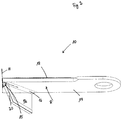
- Fig. 1 a view of a row unit 2 of an attachment is shown without the associated picking plates.
- the row unit 2 has a feed area 4 into which the stalks of the harvested crop run. Behind the intake area 4 there is a picking device 6 with which the stalks are pulled down by the rotatingly driven picking rotors. The corn cobs are plucked from the stalks on picking plates (not shown in detail in the drawing) that delimit a picking gap.
- the device 8 for cutting the stalks, which are conveyed downward with the picking device 6.
- the device 8 has one or more rotating cutting elements 10.
- the in Fig. 1 The cutting element 10 shown is shown in various rotational positions which it assumes in the course of one revolution. These cutting elements 10 cut both the stems from the stubble that remains firmly attached to the ground and the stems and leaves into smaller parts, which are carried away by the picking rotors downwards.
- the cutting elements 10 rotate in the direction of rotation R.
- the cutting elements 10 have guide surfaces 12 which extend downward from the blade plane 14.
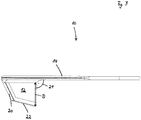
- Fig. 2 a view obliquely from below of a cutting element 10 with a guide surface 12 is shown.
- the basic rectangular shape of the blade surface is indicated by dotted lines.
- the guide surface 12 based on the front outer corner of the blade surface on which the vertical axis H is drawn, inwardly by one in the direction of rotation R of the cutting element 10
- Angle of incidence 15 is employed, the course of the angular position of the guide surface 12 in relation to the vertical axis H is indicated by a dash-dotted line.
- the guide surface 12 protrudes when the cutting element 10 rotates in the direction of rotation R into the free space that is located between the end face 20 of the guide surface 12 and the axis of rotation of the cutting element 10 below the blade plane 14 of the cutting element 10.
- the transition 16 between the blade plane 14 and the guide surface 12 is designed in the form of an arc in the exemplary embodiment.
- the end face 20 of the guide surface 12 has an obliquely running edge which falls back from the front edge 18 of the blade in the upper area towards the bottom, counter to the direction of rotation R, towards the rear.
- Fig. 3 is an end view of the in Fig. 2 shown cutting element 10 is shown.
- the lower edge 22 of the guide surface 12 slopes downwards from the front to the rear in relation to the plane of the blade 14, counter to the direction of rotation R.
- the guide surface 12 has the greatest vertical extent D in its rear third.
- the setting angle 24 of the guide surface 12 to the blade plane 14 is approximately 90 ° in the exemplary embodiment. Because of the perspective view, this angle is in Fig. 3 only recognizable on closer inspection.
- FIG Fig. 4 The approximately right angle of attack 24 between the guide surface 12 and the blade plane 14 in FIG Fig. 4 , in which a view from diagonally behind of the in the Fig. 2 and 3 cutting element shown is shown. In this view, the curved course of the transition 16 and the rearwardly sloping edge of the end face 20 can also be seen. In this view, too, the angle of incidence 15 is shown once again in dash-dotted lines, by which the guide surface 12 protrudes into the free space between the end face 20 and the axis of rotation of the cutting element 10 when the cutting element 10 rotates in the direction of rotation R.
- Fig. 5 a view from above of a cutting element 10 is shown.
- a rectangular basic shape of the cutting element 10 is indicated by dotted lines.
- the invention is not restricted to the above exemplary embodiments.
- the person skilled in the art has no difficulties in modifying the exemplary embodiments in a manner that appears suitable to him in order to adapt them to a specific application.
Description
- Die vorliegende Erfindung bezieht sich auf ein Anbaugerät zur Ernte von stängeligem Halmgut mit einer Fördervorrichtung und einer in einer Ebene unterhalb der Fördervorrichtung angeordneten Vorrichtung zum Schneiden von Stängeln, die zumindest ein in einer horizontalen oder zumindest annähernd horizontalen Ebene rotierend umlaufendes Schneidelement aufweist.
- Ein gattungsgemäßes Anbaugerät ist aus der Schrift
DE 10 2015 115 100 A1 in Gestalt eines Maispflückers bekannt. In diesem Anbaugerät läuft ein Stängel des Halmguts - wie beispielsweise einer Maispflanze - ein, der Stängel wird von Pflückwalzen nach unten gerissen und der Fruchtstand, wie beispielsweise ein Maiskolben einer Maispflanze, wird dabei von den Pflückplatten der Pflückvorrichtung vom Maisstängel abgetrennt. Die vom Stängel abgetrennten Maiskolben werden mit einer Fördervorrichtung einer Dreschvorrichtung zugeführt. Der übrig bleibende Maisstängel wird von den Pflückwalzen weiter nach unten befördert, er kann dabei auch geschnitten oder angeschnitten werden. Ein nach unten gerissener Stängel wird unterhalb der Pflückwalzen von zumindest annähernd in einer horizontalen Ebene rotierend umlaufenden Häckselmessern, die im Bereich der Pflückwalzen angeordnet sind, abgeschnitten. Die umlaufenden Häckselmesser schneiden von den Pflückwalzen nach unten beförderte Stängelstücke in noch kürzere Stängelstücke, die dann auf das Feld abgeworfen werden. Dort können die Stängelstücke dann verrotten. Die umlaufenden Schneidelemente sollen die Stoppeln aufspleissen und das Stroh der geschnittenen Stängel auf dem Boden verteilen. - Die umlaufend rotierenden Häckselmesser schneiden je nach Höheneinstellung des Anbaugeräts nicht nur die von den Pflückwalzen nach unten gerissenen Stängelstücke, sondern sie kappen auch die überstehenden Enden der Stoppeln der Maispflanzen, die nach dem Abtrennen der Stängel noch auf dem Acker stehen. Ein Beispiel für diese Arbeitsweise findet sich in der Schrift
DE 102 50 302 B4 . Die verbleibenden Stoppel werden jedoch nicht weiter aufgespleisst und von den Reifen der Erntemaschine oder sonstigen Fahrzeugen auf dem Feld in den Boden gedrückt, wo sie von Mikroorganismen nur sehr schwer zersetzt werden können. Häufig ist noch eine gesonderte Stoppelnachbearbeitung erforderlich, bei der die Stoppel nach der Ernte so geschädigt werden müssen, dass sie noch vor der Aussaat der nachfolgenden Frucht ausreichend verrottet sind. Dafür ist ein zusätzlicher Arbeitsaufwand erforderlich, und die zusätzliche Überfahrt über das Feld verdichtet den Boden unnötig. - Es hat sich gezeigt, dass bei den hohen Drehzahlen der rotierenden Häckselmesser einiger Staub durch aufgewirbeltes Erntegut erzeugt wird, der die Sicht des Fahrers auf den Erntevorsatz behindert. Das Stroh der geschnittenen Stängel wird schwadartig auf eine Stoppelreihe abgelegt und nicht ausreichend verteilt. Des Weiteren ist es nicht ausgeschlossen, dass die rotierenden Häckselmesser in ihrer umlaufenden Bewegung an Fremdkörper wie beispielsweise Steine anstoßen, die dann von dem jeweils berührenden Häckselmesser weggeschleudert werden. Das ist potentiell gefährlich.
- Die vorstehend für Maispflücker beschriebenen technischen Probleme bestehen grundsätzlich in gleicher Weise bei Maisgebissen, die die Maisstängel nur schneiden und abfördern, damit die abgeschnittenen Pflanzen in ihrer Gesamtheit zu Silagefutter in einem Feldhäcksler kleingehäckselt werden. Bei solchen Anbaugeräten entfallen die Pflückvorrichtungen und der Abwurf der von den Kolben getrennten Pflanzenbestandteile auf das Feld. Die Pflanzenstängel werden nicht durch umlaufende Häckselmesser mehrfach zerkleinert, sondern nur einmalig durch eine unterhalb der Förderorgane angeordnete Messerscheibe als Schneidelement geschnitten. Auch hier fehlt es jedoch an einer geeigneten Stoppelbearbeitung durch die rotierenden Schneidelemente des Anbaugeräts in Gestalt der Schneidscheiben.
- Es ist die Aufgabe der vorliegenden Erfindung, die aus dem Stand der Technik bekannten nachteiligen Effekte nach Möglichkeit zu vermindern.
- Die Aufgabe wird für ein gattungsgemäßes Anbaugerät gelöst, indem das Schneidelement an seinem äußeren Rand eine Leitfläche aufweist, die sich von der Klingenebene aus abwärts erstreckt, wobei die Leitfläche in Rotationsrichtung des Schneidelements nach innen um einen Anstellwinkel angestellt ist.
- Die Leitfläche fördert die Luft, die Biomasse sowie andere Raumkörper, die von der Leitfläche erfasst werden, auf die Rotationsachse des rotierend umlaufenden Schneidelements zu, also nach innen hin. Bei einer üblichen hohen Drehzahl des Schneidelements bildet dieses zusammen mit der seitlichen Leitfläche innerhalb seines Hüllkreises eine Art Glocke oder Käfig, in dessen Innenraum die Luft, die Biomasse sowie andere Raumkörper, die in den Wirkbereich der Leitfläche gelangt sind, miteinander vermischt werden. Die Glocke oder der Käfig sind nach oben und zur Seite hin durch das mit einer hohen Geschwindigkeit rotierende Schneidelement mit der sich nach unten erstreckenden Leitfläche quasi geschlossen. Die Schneidelemente sind üblicherweise in einer zentralen Halterung gehalten, die nach oben hin geschlossen ausgeführt ist. Die von den rotierenden Leitflächen nach innen beförderte Luft, die Biomasse und die sonstigen Raumkörper, die von der Leitfläche eines Schneidelements nach innen befördert worden sind, können deshalb von der Mitte des Innenraums aus nicht nach oben hin ausweichen. Das in der Glocke oder dem Käfig befindliche Material kann somit nur nach unten aus dem Innenraum heraus gelangen.
- Die Länge der Leitfläche ist ausgelegt auf die Vorfahrtgeschwindigkeit, mit der die Erntemaschine, die das Anbaugerät trägt, üblicherweise in den Bestand des Ernteguts hineinfährt, sowie auf die Rotationsgeschwindigkeit, mit der die Schneidelemente umlaufen. Die Länge der Leitfläche sollte bei der gegebenen Vorfahrtgeschwindigkeit und Rotationsgeschwindigkeit ausreichen, um die Stoppel ausreichend zu zerfasern und aufzuspleissen.
- Vom dem nach unten ausweichenden Luftstrom, den die rotierenden Leitflächen erzeugen, wird das geschnittene Stroh und andere Raumkörper mitgenommen und auf den Ackerboden zwischen die Stoppeln gedrückt. Daraus ergibt sich ein Gutfluss, der von der Seite her Luft, die Biomasse sowie andere Raumkörper, die in den Wirkbereich der Leitfläche gelangt sind, mit einem Sog im äußeren Umfangsbereich der Leitflächen und einem Überdruck an der Innenfläche nach innen hin zusammenführt und sodann über die Fläche des Hüllkreises des oder der rotierenden Schneidelemente auf den Boden bläst, weil die angesammelten Bestandteile nur in diese Richtung aus dem Wirkbereich des Schneidelements mit den Leitflächen gelangen können. Dadurch wird auch der Überdruck aus der angesammelten Luft innerhalb der Glocke mit dem Luftstrom nach unten hin abgebaut. Das gehäckselte Stroh wird auf diese Weise gleichmäßiger auf dem Ackerboden verteilt. Im Arbeitsbereich des Erntevorsatzes fliegt weniger Material unkontrolliert herum, so dass der Betrieb des Erntevorsatzgeräts insgesamt sicherer wird.
- Die Wirkung eines rotierenden Schneidelements als eine Art Glocke oder Käfig ist umso stärker, je schneller und/oder je mehr Schneidelemente mit Leitfläche um eine gemeinsame Rotationsachse rotieren. So können beispielsweise zwei, drei oder vier Schneidelemente vorhanden sein, die um eine gemeinsame Rotationsachse drehen.
- Bei der erfindungsgemäßen Ausgestaltung des Schneidelements ist die Staubentwicklung deutlich verringert. Durch den nach unten gerichteten Abwind aus der Häckselvorrichtung wird staubbelastete Luft vom Gutstrom mitgenommen und zusammen mit den gehäckselten Pflanzenresten auf den Ackerboden geblasen.
- Die Leitfläche an dem rotierenden Schneidelement ist aber nicht nur vorteilhaft für die Strohverteilung auf die abgeerntete Fläche, sie zerspleisst und zerschlägt auch beim Auftreffen auf einen Stoppel dessen Struktur und zerfasert ihn bis weit unter die Klingenebene hinab, die nach dem Stand der Technik mit der Klinge nicht mehr erreichbar wäre. Der Stoppel ist nach dem Kontakt mit der Leitfläche für Mikroorganismen leichter zugänglich, wodurch die Verrottung des Stoppels gefördert wird. Je nach Rotationsgeschwindigkeit und Zahl der rotierenden Schneidelemente kann ein einzelner Stoppel bei der Überfahrt mit einer Erntemaschine mehrfach von einer Leitfläche getroffen werden, wodurch ein Stoppel noch besser aufgespleisst und zerschlagen wird. Eine Stoppelnachbearbeitung in einem weiteren Arbeitsgang auf dem Feld ist nicht mehr erforderlich.
- Nach einer Ausgestaltung der Erfindung verläuft der Übergang von der Klingenebene zur Leitfläche in einem gerundeten Bogen. Eine Anbindung der Leitfläche in einem gerundeten Bogen vermag höhere Kraftspitzen aufzunehmen als eine scharfe Kante im Übergangsbereich. Das Schneidelement ist auf diese Weise widerstandsfähiger gegen einen Kontakt mit Fremdkörpern.
- Nach einer Ausgestaltung der Erfindung ist die Leitfläche in einem Anstellwinkel von mehr als 15° zur Senkrechten auf die Klingenvorderkante nach innen weisend angestellt. Durch die ausgeprägte Schrägstellung der Leitfläche im Verhältnis zur Rotationsrichtung des Schneidelements ergibt sich eine ausreichend große Förder- und Aufspleisswirkung der Leitfläche. Auch die Luftförderwirkung der Leitfläche, die auf den Gutfluss und den Abwurf der Stängelstücke auf das Feld einen erheblichen Einfluss ausübt, ist bei der vorgeschlagenen Gestaltung vorteilhaft.
- Nach einer Ausgestaltung der Erfindung weist die Leitfläche an ihrer in Rotationsrichtung weisenden Stirnseite eine schräg verlaufende Kante auf, die von der Klingenvorderkante im oberen Bereich nach unten hin entgegen der Rotationsrichtung nach hinten zurückfällt. Durch die schräg verlaufende Kante prallt die Stirnseite der Leitfläche nicht stumpf mit ihrer gesamten Fläche gegen die Außenseite eines Stoppels, sondern kann nach Art eines ziehenden Schnittes zunehmend in das Material des Stoppels einziehen, ohne dass dabei allzu hohe Kraftspitzen entstehen.
- Nach einer Ausgestaltung der Erfindung fällt die Unterkante der Leitfläche entgegen der Rotationsrichtung von vorne nach hinten im Verhältnis zur Klingenebene nach unten ab. Durch die abfallende Form kann die Leitfläche bei einem Boden- oder Fremdkörperkontakt in Rotationsrichtung von vorne nach hinten auf den Boden beziehungsweise den Fremdkörper aufgleiten. Die Schneidelementklinge wird dadurch während der Rotationsbewegung nach oben hin angehoben. Der Verschleiß und die Bruchgefahr werden dadurch reduziert. Das Schneidelement kann dadurch über die Höheneinstellung des Anbaugeräts sehr dicht am Feldboden entlang geführt werden. Die Stoppeln werden dadurch sehr dicht über dem Boden von den Leitflächen erfasst und zerfastert.
- Nach einer Ausgestaltung der Erfindung weist die Leitfläche in ihrem hinteren Drittel die größte Höhenerstreckung auf. Da sich getroffene Stoppel nach dem Erstkontakt mit der Leitfläche nach unten und zur Seite wegbewegen, würden die entgegen der Rotationsrichtung gelegenen hinteren Teile der Leitfläche keinen oder nur noch einen unwesentlichen Kontakt zum Erntegut bekommen, wenn die Leitfläche in diesem Bereich nicht weiter nach unten reichen würde als in dem Teil der Leitfläche, die in Rotationsrichtung gesehen weiter vorne ausgebildet ist. Der Verschleiß und die Arbeitsleistung der Leitfläche sind auf diese Weise besser über die Gesamtfläche der Leitfläche verteilt.
- Nach einer Ausgestaltung der Erfindung beträgt der Anstellwinkel der Leitfläche zur Klingenebene in radialer Richtung von der Schwenkachse des Schneidelements und in vertikaler Richtung zum Boden 80° bis 100°. Bei einem genau oder etwa 90° betragenden Anstellwinkel ergibt sich eine gute Funktion der Leitfläche.
- Nach einer Ausgestaltung der Erfindung weisen die Stirnseite und/oder die Unterkante der Leitfläche gegenüber dem übrigen Material der Leitfläche eine Materialhärtung auf. Da diese Bereiche der Leitfläche einer besonderen Belastung und einem hohem Verschleiß unterliegen, ist eine entsprechende Materialhärtung vorteilhaft.
- Nach einer Ausgestaltung der Erfindung ist auf die Leitfläche eine auswechselbare Verschleißplatte aufgesetzt. Im Bereich der Leitfläche ist mit einem erheblichen Verschleiß zu rechnen, der höher ist als der Verschleiß der Klingen des Schneidelements. Durch die Verschleißplatte muss nicht das gesamte Schneidelement ausgetauscht werden, wenn im Bereich der Leitfläche ein erheblicher Verscheiß eingetreten ist, sondern es genügt, die Verschleißplatten auszutauschen. Die Schneidelemente erhalten dadurch insgesamt eine längere Standzeit, und die Schneidelemente müssen nicht häufiger getauscht werden, als es der Fall wäre, wenn sie keine Leitflächen aufweisen würden.
- Weitere Merkmale der Erfindung ergeben sich aus den Ansprüchen, den Figuren und der gegenständlichen Beschreibung. Alle vorstehend in der Beschreibung genannten Merkmale und Merkmalskombinationen sowie die nachfolgend in der Figurenbeschreibung genannten und/oder in den Figuren alleine gezeigten Merkmale und Merkmalskombinationen sind nicht nur in der jeweils angegebenen Kombination, sondern auch in anderen Kombinationen oder aber in Alleinstellung verwendbar.
- Die Erfindung wird nun anhand eines bevorzugten Ausführungsbeispiels sowie unter Bezugnahme auf die beigefügten Zeichnungen näher erläutert.
- Es zeigen:
- Fig. 1:
- eine Ansicht auf ein Reihenaggregat eines Anbaugeräts,
- Fig. 2:
- eine Ansicht von schräg unten auf ein Schneidelement mit Leitfläche,
- Fig. 3:
- eine stirnseitige Ansicht des in
Fig. 2 gezeigten Schneidelements, - Fig. 4:
- eine Ansicht von schräg hinten auf das in den
Fig. 2 und3 gezeigte Schneidelement, und - Fig. 5:
- eine Ansicht von oben auf ein Schneidelement.
- In
Fig. 1 ist eine Ansicht auf ein Reihenaggregat 2 eines Anbaugeräts ohne die zugehörigen Pflückplatten gezeigt. Das Reihenaggregat 2 verfügt über einen Einzugsbereich 4, in den die Stängel des Ernteguts einlaufen. Hinter dem Einzugsbereich 4 befindet sich eine Pflückvorrichtung 6, mit der die Stängel von den rotierend angetriebenen Pflückrotoren nach unten gezogen werden. Dabei werden die Maiskolben an zeichnerisch nicht näher dargestellten Pflückplatten, die einen Pflückspalt begrenzen, von den Stängeln abgepflückt. - Unterhalb der Pflückvorrichtung 6 befindet sich eine Vorrichtung 8 zum Schneiden der Stängel, die mit der Pflückvorrichtung 6 nach unten befördert werden. Die Vorrichtung 8 verfügt über ein oder mehrere rotierende Schneidelemente 10. Das in
Fig. 1 gezeigte Schneidelement 10 ist in verschiedenen Drehstellungen gezeigt, die es im Verlauf einer Umdrehung einnimmt. Diese Schneidelemente 10 schneiden sowohl die Stängel von den mit dem Boden fest verbundenen bleibenden Stoppeln ab als auch die Stängel und Blätter in kleinere Teile, die von den Pflückrotoren nach unten abgefördert werden. Die Schneidelemente 10 rotieren in die Rotationsrichtung R. Die Schneidelemente 10 verfügen über Leitflächen 12, die sich von der Klingenebene 14 aus abwärts erstrecken. - In
Fig. 2 ist eine Ansicht von schräg unten auf ein Schneidelement 10 mit einer Leitfläche 12 gezeigt. Die rechteckige Grundform der Klingenfläche ist durch punktierte Linien angedeutet. In dieser Ansicht ist erkennbar, dass die Leitfläche 12 bezogen auf die vordere äußere Ecke der Klingenfläche, auf die die Hochachse H eingezeichnet ist, in Rotationsrichtung R des Schneidelements 10 nach innen um einen Anstellwinkel 15 angestellt ist, wobei der Verlauf der Winkelstellung der Leitfläche 12 im Verhältnis zur Hochachse H durch eine strichpunktierte Linie angedeutet ist. Durch den Anstellwinkel 15 ragt die Leitfläche 12 bei einer Rotationsbewegung des Schneidelements 10 in Rotationsrichtung R in den Freiraum hinein, der sich zwischen der Stirnseite 20 der Leitfläche 12 und der Rotationsachse des Schneidelements 10 unterhalb der Klingenebene 14 des Schneidelements 10 befindet. - Der Übergang 16 zwischen der Klingenebene 14 und der Leitfläche 12 ist im Ausführungsbeispiel bogenförmig gestaltet.
- Die Stirnseite 20 der Leitfläche 12 weist eine schräg verlaufende Kante auf, die von der Klingenvorderkante 18 im oberen Bereich nach unten hin entgegen der Rotationsrichtung R nach hinten zurückfällt.
- In
Fig. 3 ist eine stirnseitige Ansicht des inFig. 2 gezeigten Schneidelements 10 gezeigt. In dieser Ansicht ist erkennbar, wie weit die Leitfläche 12 in den Freiraum zwischen der Stirnseite 20 und der Rotationsachse des Schneidelements 10 hineinragt. In dieser Ansicht ist auch gut die schräg verlaufende Kante im Bereich der Stirnseite 20 zu erkennen. Die Unterkante 22 der Leitfläche 12 fällt entgegen der Rotationsrichtung R von vorne nach hinten im Verhältnis zur Klingenebene 14 nach unten ab. In ihrem hinteren Drittel weist die Leitfläche 12 die größte Höhenerstreckung D auf. Der Anstellwinkel 24 der Leitfläche 12 zur Klingenebene 14 beträgt im Ausführungsbeispiel etwa 90°. Aufgrund der perspektivischen Ansicht ist dieser Winkel inFig. 3 erst bei genauerer Betrachtung erkennbar. - Besser erkennbar ist der annähernd rechte Anstellwinkel 24 zwischen der Leitfläche 12 und der Klingenebene 14 in der
Fig. 4 , in der eine Ansicht von schräg hinten auf das in denFig. 2 und3 gezeigte Schneidelement gezeigt ist. In dieser Ansicht ist auch der bogenförmige Verlauf des Übergangs 16 sowie die nach hinten abfallende Kante der Stirnseite 20 erkennbar. Auch in dieser Ansicht ist noch einmal in strichpunktierter Linie der Anstellwinkel 15 gezeigt, um den die Leitfläche 12 bei einer Rotationsbewegung des Schneidelements 10 in Rotationsrichtung R in den Freiraum zwischen der Stirnseite 20 und der Rotationsachse des Schneidelements 10 hineinragt. - In
Fig. 5 ist eine Ansicht von oben auf ein Schneidelement 10 gezeigt. Auch hier ist eine rechteckige Grundform des Schneidelements 10 durch gepunktete Linien angedeutet. - Die Erfindung ist nicht auf die vorstehenden Ausführungsbeispiele beschränkt. Dem Fachmann bereitet es keine Schwierigkeiten, die Ausführungsbeispiele auf eine ihm geeignet erscheinende Weise abzuwandeln, um sie an einen konkreten Anwendungsfall anzupassen.
Claims (9)
- Anbaugerät zur Ernte von stängeligem Halmgut mit einer Fördervorrichtung und einer in einer Ebene unterhalb der Fördervorrichtung angeordneten Vorrichtung (8) zum Schneiden von Stängeln, die zumindest ein in einer horizontalen oder zumindest annähernd horizontalen Ebene rotierend umlaufendes Schneidelement (10) aufweist, dadurch gekennzeichnet, dass das Schneidelement (10) an seinem äußeren Rand eine Leitfläche (12) aufweist, die sich von der Klingenebene (14) aus abwärts erstreckt, wobei die Leitfläche (12) in Rotationsrichtung (R) des Schneidelements (10) nach innen um einen Anstellwinkel (15) angestellt ist.
- Anbaugerät nach Anspruch 1, dadurch gekennzeichnet, dass der Übergang (16) von der Klingenebene (14) zur Leitfläche (12) in einem gerundeten Bogen verläuft.
- Anbaugerät nach Anspruch 1 oder 2, dadurch gekennzeichnet, dass die Leitfläche (12) in einem Anstellwinkel (15) von mehr als 15° zur Senkrechten auf die Klingenvorderkante (18) nach innen weisend angestellt ist.
- Anbaugerät nach einem der vorhergehenden Ansprüche, dadurch gekennzeichnet, dass die Leitfläche (12) an ihrer in Rotationsrichtung (R) weisenden Stirnseite (20) eine schräg verlaufende Kante aufweist, die von der Klingenvorderkante (18) im oberen Bereich nach unten hin entgegen der Rotationsrichtung (R) nach hinten zurückfällt.
- Anbaugerät nach einem der vorhergehenden Ansprüche, dadurch gekennzeichnet, dass die Unterkante (22) der Leitfläche (12) entgegen der Rotationsrichtung (R) von vorne nach hinten im Verhältnis zur Klingenebene (14) nach unten abfällt.
- Anbaugerät nach einem der vorhergehenden Ansprüche, dadurch gekennzeichnet, dass die Leitfläche (12) in ihrem hinteren Drittel die größte Höhenerstreckung (D) aufweist.
- Anbaugerät nach einem der vorhergehenden Ansprüche, dadurch gekennzeichnet, dass der Anstellwinkel (24) der Leitfläche (12) zur Klingenebene (14) in radialer Richtung von der Schwenkachse des Schneidelements (10) und in vertikaler Richtung zum Boden 80° bis 100° beträgt.
- Anbaugerät nach einem der vorhergehenden Ansprüche, dadurch gekennzeichnet, dass die Stirnseite (20) und/oder die Unterkante (22) der Leitfläche (12) gegenüber dem übrigen Material der Leitfläche (12) eine Materialhärtung aufweisen.
- Anbaugerät nach einem der vorhergehenden Ansprüche, dadurch gekennzeichnet, dass auf die Leitfläche (12) eine auswechselbare Verschleißplatte aufgesetzt ist.
Priority Applications (1)
| Application Number | Priority Date | Filing Date | Title |
|---|---|---|---|
| PL18793375T PL3697196T3 (pl) | 2017-10-18 | 2018-10-16 | Element ścinający z cięciem ciągnącym |
Applications Claiming Priority (2)
| Application Number | Priority Date | Filing Date | Title |
|---|---|---|---|
| DE102017124324.0A DE102017124324A1 (de) | 2017-10-18 | 2017-10-18 | Schneidelement mit ziehendem Schnitt |
| PCT/EP2018/078261 WO2019076905A1 (de) | 2017-10-18 | 2018-10-16 | Schneidelement mit ziehendem schnitt |
Publications (2)
| Publication Number | Publication Date |
|---|---|
| EP3697196A1 EP3697196A1 (de) | 2020-08-26 |
| EP3697196B1 true EP3697196B1 (de) | 2021-11-24 |
Family
ID=64017345
Family Applications (1)
| Application Number | Title | Priority Date | Filing Date |
|---|---|---|---|
| EP18793375.9A Active EP3697196B1 (de) | 2017-10-18 | 2018-10-16 | Schneidelement mit ziehendem schnitt |
Country Status (5)
| Country | Link |
|---|---|
| EP (1) | EP3697196B1 (de) |
| DE (1) | DE102017124324A1 (de) |
| HU (1) | HUE057752T2 (de) |
| PL (1) | PL3697196T3 (de) |
| WO (1) | WO2019076905A1 (de) |
Families Citing this family (1)
| Publication number | Priority date | Publication date | Assignee | Title |
|---|---|---|---|---|
| CN112889456A (zh) * | 2021-01-19 | 2021-06-04 | 中国热带农业科学院热带生物技术研究所 | 木薯茎秆割取还田一体机 |
Family Cites Families (6)
| Publication number | Priority date | Publication date | Assignee | Title |
|---|---|---|---|---|
| US2891369A (en) * | 1953-07-07 | 1959-06-23 | Auto Specialties Mfg Co | Rotary shredder and cutter |
| US2815631A (en) * | 1954-09-01 | 1957-12-10 | John Deere Plow Company | Rotary mower |
| GB2000951B (en) * | 1977-07-14 | 1982-02-17 | Surridge G P | Lawn cultivating cutter assembly for rotary mower |
| DE10250302B4 (de) | 2002-10-29 | 2004-12-09 | Bayerische Motoren Werke Ag | Drallerzeugungseinrichtung für einen Verdichter |
| US20130111863A1 (en) * | 2011-11-07 | 2013-05-09 | Kondex Corporation | Disc Mower Blades |
| DE102015115100A1 (de) | 2015-09-08 | 2017-03-09 | Carl Geringhoff Gmbh & Co. Kg | Vorrichtung zur Ernte von stängeligem Halmgut |
-
2017
- 2017-10-18 DE DE102017124324.0A patent/DE102017124324A1/de not_active Withdrawn
-
2018
- 2018-10-16 PL PL18793375T patent/PL3697196T3/pl unknown
- 2018-10-16 EP EP18793375.9A patent/EP3697196B1/de active Active
- 2018-10-16 WO PCT/EP2018/078261 patent/WO2019076905A1/de unknown
- 2018-10-16 HU HUE18793375A patent/HUE057752T2/hu unknown
Also Published As
| Publication number | Publication date |
|---|---|
| WO2019076905A1 (de) | 2019-04-25 |
| PL3697196T3 (pl) | 2022-03-21 |
| EP3697196A1 (de) | 2020-08-26 |
| HUE057752T2 (hu) | 2022-06-28 |
| DE102017124324A1 (de) | 2019-04-18 |
Similar Documents
| Publication | Publication Date | Title |
|---|---|---|
| EP2255610B1 (de) | Vorsatzgerät zum Ernten stängelförmiger Pflanzen | |
| EP3272199B1 (de) | Mulchgerät zur bearbeitung von auf einem feld stehenden pflanzenstümpfen | |
| EP1566092B1 (de) | Erntegerät mit einem Stängelhäcksler | |
| EP2965611B1 (de) | Stängelhäcksler für ein maiserntegerät | |
| DE102007009587A1 (de) | Vorrichtung zur Einstellung der Position des Nachbeschleunigungsorgans in einer landwirtschaftlichen Erntemaschine | |
| DE102012206720A1 (de) | Maschine zur Ernte stängelartiger Pflanzen mit einem unterhalb einer Schneidscheibe angeordneten Schlagkörper zum Zerfasern der Stoppeln | |
| DE102015206845A1 (de) | Schneidwerk zur Ganzpflanzenernte | |
| DE102012106602A1 (de) | Vorsatzgerät zum Ernten von Mais | |
| DE102006048659A1 (de) | Maschine zur Ernte stängelartiger Pflanzen mit einem Abstreifer und einem diesem nachgeordneten Führungselement | |
| DE102014219694A1 (de) | Maiserntegerät mit Pflanzenstoppelzieher und -häcksler | |
| DE102016212621A1 (de) | Erntevorsatz mit einer Mulcheinrichtung | |
| WO2015000768A1 (de) | Landwirtschaftliches gerät und verfahren zur bearbeitung von pflanzenstoppeln | |
| DE102010028599A1 (de) | Erntegutrestehäcksel- und -verteilanordnung für einen Mähdrescher | |
| DE10108505A1 (de) | Maschine zum Mähen von stängelartigem Erntegut | |
| DE102015220560B4 (de) | Mähdrescher mit einem zum Wechsel zwischen Schwadablagebetrieb und Häckselbetrieb in unterschiedlichen Drehrichtungen antreibbaren Strohhäcksler | |
| EP3697196B1 (de) | Schneidelement mit ziehendem schnitt | |
| DE102016214323A1 (de) | Mulcheinrichtung zur mechanischen Bearbeitung von Pflanzenstoppeln | |
| DE102007035797B4 (de) | Mäh- und Einzugseinrichtung für eine Maschine zur Ernte von stängelartigem Erntegut mit zwei wahlweise daran anbringbaren Stängelheberspitzen | |
| DE3825125C2 (de) | ||
| EP3092885B1 (de) | Mähmaschine | |
| DE102019007585A1 (de) | Reihenunabhängiges Vorsatzgerät zum Ernten stängelförmiger Pflanzen mit einem quer zur Fahrtrichtung liegenden, durch das ganze Vorsatzgerät durchgehenden Pflückspalt | |
| EP1566091B1 (de) | Erntegerät mit einem Stängelhäcksler | |
| DE102014118678B4 (de) | Maisgebiss für einen Feldhäcksler und Feldhäcksler | |
| DE2436308A1 (de) | Mehrzweckgeraet zum aufnehmen, zerkleinern und verteilen von auf schwaden liegendem stroh und dergleichen | |
| DE102022127703A1 (de) | Erntevorsatz zur Ganzpflanzenernte |
Legal Events
| Date | Code | Title | Description |
|---|---|---|---|
| STAA | Information on the status of an ep patent application or granted ep patent |
Free format text: STATUS: UNKNOWN |
|
| STAA | Information on the status of an ep patent application or granted ep patent |
Free format text: STATUS: THE INTERNATIONAL PUBLICATION HAS BEEN MADE |
|
| PUAI | Public reference made under article 153(3) epc to a published international application that has entered the european phase |
Free format text: ORIGINAL CODE: 0009012 |
|
| STAA | Information on the status of an ep patent application or granted ep patent |
Free format text: STATUS: REQUEST FOR EXAMINATION WAS MADE |
|
| 17P | Request for examination filed |
Effective date: 20200330 |
|
| AK | Designated contracting states |
Kind code of ref document: A1 Designated state(s): AL AT BE BG CH CY CZ DE DK EE ES FI FR GB GR HR HU IE IS IT LI LT LU LV MC MK MT NL NO PL PT RO RS SE SI SK SM TR |
|
| AX | Request for extension of the european patent |
Extension state: BA ME |
|
| DAV | Request for validation of the european patent (deleted) | ||
| DAX | Request for extension of the european patent (deleted) | ||
| GRAP | Despatch of communication of intention to grant a patent |
Free format text: ORIGINAL CODE: EPIDOSNIGR1 |
|
| STAA | Information on the status of an ep patent application or granted ep patent |
Free format text: STATUS: GRANT OF PATENT IS INTENDED |
|
| INTG | Intention to grant announced |
Effective date: 20210617 |
|
| GRAS | Grant fee paid |
Free format text: ORIGINAL CODE: EPIDOSNIGR3 |
|
| GRAA | (expected) grant |
Free format text: ORIGINAL CODE: 0009210 |
|
| STAA | Information on the status of an ep patent application or granted ep patent |
Free format text: STATUS: THE PATENT HAS BEEN GRANTED |
|
| AK | Designated contracting states |
Kind code of ref document: B1 Designated state(s): AL AT BE BG CH CY CZ DE DK EE ES FI FR GB GR HR HU IE IS IT LI LT LU LV MC MK MT NL NO PL PT RO RS SE SI SK SM TR |
|
| REG | Reference to a national code |
Ref country code: GB Ref legal event code: FG4D Free format text: NOT ENGLISH |
|
| REG | Reference to a national code |
Ref country code: AT Ref legal event code: REF Ref document number: 1449121 Country of ref document: AT Kind code of ref document: T Effective date: 20211215 |
|
| REG | Reference to a national code |
Ref country code: DE Ref legal event code: R096 Ref document number: 502018007993 Country of ref document: DE |
|
| REG | Reference to a national code |
Ref country code: IE Ref legal event code: FG4D Free format text: LANGUAGE OF EP DOCUMENT: GERMAN |
|
| REG | Reference to a national code |
Ref country code: LT Ref legal event code: MG9D |
|
| REG | Reference to a national code |
Ref country code: NL Ref legal event code: MP Effective date: 20211124 |
|
| PG25 | Lapsed in a contracting state [announced via postgrant information from national office to epo] |
Ref country code: RS Free format text: LAPSE BECAUSE OF FAILURE TO SUBMIT A TRANSLATION OF THE DESCRIPTION OR TO PAY THE FEE WITHIN THE PRESCRIBED TIME-LIMIT Effective date: 20211124 Ref country code: LT Free format text: LAPSE BECAUSE OF FAILURE TO SUBMIT A TRANSLATION OF THE DESCRIPTION OR TO PAY THE FEE WITHIN THE PRESCRIBED TIME-LIMIT Effective date: 20211124 Ref country code: FI Free format text: LAPSE BECAUSE OF FAILURE TO SUBMIT A TRANSLATION OF THE DESCRIPTION OR TO PAY THE FEE WITHIN THE PRESCRIBED TIME-LIMIT Effective date: 20211124 Ref country code: BG Free format text: LAPSE BECAUSE OF FAILURE TO SUBMIT A TRANSLATION OF THE DESCRIPTION OR TO PAY THE FEE WITHIN THE PRESCRIBED TIME-LIMIT Effective date: 20220224 |
|
| PG25 | Lapsed in a contracting state [announced via postgrant information from national office to epo] |
Ref country code: IS Free format text: LAPSE BECAUSE OF FAILURE TO SUBMIT A TRANSLATION OF THE DESCRIPTION OR TO PAY THE FEE WITHIN THE PRESCRIBED TIME-LIMIT Effective date: 20220324 Ref country code: SE Free format text: LAPSE BECAUSE OF FAILURE TO SUBMIT A TRANSLATION OF THE DESCRIPTION OR TO PAY THE FEE WITHIN THE PRESCRIBED TIME-LIMIT Effective date: 20211124 Ref country code: PT Free format text: LAPSE BECAUSE OF FAILURE TO SUBMIT A TRANSLATION OF THE DESCRIPTION OR TO PAY THE FEE WITHIN THE PRESCRIBED TIME-LIMIT Effective date: 20220324 Ref country code: NO Free format text: LAPSE BECAUSE OF FAILURE TO SUBMIT A TRANSLATION OF THE DESCRIPTION OR TO PAY THE FEE WITHIN THE PRESCRIBED TIME-LIMIT Effective date: 20220224 Ref country code: NL Free format text: LAPSE BECAUSE OF FAILURE TO SUBMIT A TRANSLATION OF THE DESCRIPTION OR TO PAY THE FEE WITHIN THE PRESCRIBED TIME-LIMIT Effective date: 20211124 Ref country code: LV Free format text: LAPSE BECAUSE OF FAILURE TO SUBMIT A TRANSLATION OF THE DESCRIPTION OR TO PAY THE FEE WITHIN THE PRESCRIBED TIME-LIMIT Effective date: 20211124 Ref country code: HR Free format text: LAPSE BECAUSE OF FAILURE TO SUBMIT A TRANSLATION OF THE DESCRIPTION OR TO PAY THE FEE WITHIN THE PRESCRIBED TIME-LIMIT Effective date: 20211124 Ref country code: GR Free format text: LAPSE BECAUSE OF FAILURE TO SUBMIT A TRANSLATION OF THE DESCRIPTION OR TO PAY THE FEE WITHIN THE PRESCRIBED TIME-LIMIT Effective date: 20220225 |
|
| REG | Reference to a national code |
Ref country code: HU Ref legal event code: AG4A Ref document number: E057752 Country of ref document: HU |
|
| PG25 | Lapsed in a contracting state [announced via postgrant information from national office to epo] |
Ref country code: SM Free format text: LAPSE BECAUSE OF FAILURE TO SUBMIT A TRANSLATION OF THE DESCRIPTION OR TO PAY THE FEE WITHIN THE PRESCRIBED TIME-LIMIT Effective date: 20211124 Ref country code: SK Free format text: LAPSE BECAUSE OF FAILURE TO SUBMIT A TRANSLATION OF THE DESCRIPTION OR TO PAY THE FEE WITHIN THE PRESCRIBED TIME-LIMIT Effective date: 20211124 Ref country code: RO Free format text: LAPSE BECAUSE OF FAILURE TO SUBMIT A TRANSLATION OF THE DESCRIPTION OR TO PAY THE FEE WITHIN THE PRESCRIBED TIME-LIMIT Effective date: 20211124 Ref country code: ES Free format text: LAPSE BECAUSE OF FAILURE TO SUBMIT A TRANSLATION OF THE DESCRIPTION OR TO PAY THE FEE WITHIN THE PRESCRIBED TIME-LIMIT Effective date: 20211124 Ref country code: EE Free format text: LAPSE BECAUSE OF FAILURE TO SUBMIT A TRANSLATION OF THE DESCRIPTION OR TO PAY THE FEE WITHIN THE PRESCRIBED TIME-LIMIT Effective date: 20211124 Ref country code: DK Free format text: LAPSE BECAUSE OF FAILURE TO SUBMIT A TRANSLATION OF THE DESCRIPTION OR TO PAY THE FEE WITHIN THE PRESCRIBED TIME-LIMIT Effective date: 20211124 Ref country code: CZ Free format text: LAPSE BECAUSE OF FAILURE TO SUBMIT A TRANSLATION OF THE DESCRIPTION OR TO PAY THE FEE WITHIN THE PRESCRIBED TIME-LIMIT Effective date: 20211124 |
|
| REG | Reference to a national code |
Ref country code: DE Ref legal event code: R097 Ref document number: 502018007993 Country of ref document: DE |
|
| PLBE | No opposition filed within time limit |
Free format text: ORIGINAL CODE: 0009261 |
|
| STAA | Information on the status of an ep patent application or granted ep patent |
Free format text: STATUS: NO OPPOSITION FILED WITHIN TIME LIMIT |
|
| PG25 | Lapsed in a contracting state [announced via postgrant information from national office to epo] |
Ref country code: AL Free format text: LAPSE BECAUSE OF FAILURE TO SUBMIT A TRANSLATION OF THE DESCRIPTION OR TO PAY THE FEE WITHIN THE PRESCRIBED TIME-LIMIT Effective date: 20211124 |
|
| 26N | No opposition filed |
Effective date: 20220825 |
|
| PG25 | Lapsed in a contracting state [announced via postgrant information from national office to epo] |
Ref country code: SI Free format text: LAPSE BECAUSE OF FAILURE TO SUBMIT A TRANSLATION OF THE DESCRIPTION OR TO PAY THE FEE WITHIN THE PRESCRIBED TIME-LIMIT Effective date: 20211124 |
|
| PG25 | Lapsed in a contracting state [announced via postgrant information from national office to epo] |
Ref country code: MC Free format text: LAPSE BECAUSE OF FAILURE TO SUBMIT A TRANSLATION OF THE DESCRIPTION OR TO PAY THE FEE WITHIN THE PRESCRIBED TIME-LIMIT Effective date: 20211124 Ref country code: IT Free format text: LAPSE BECAUSE OF FAILURE TO SUBMIT A TRANSLATION OF THE DESCRIPTION OR TO PAY THE FEE WITHIN THE PRESCRIBED TIME-LIMIT Effective date: 20211124 |
|
| REG | Reference to a national code |
Ref country code: CH Ref legal event code: PL |
|
| GBPC | Gb: european patent ceased through non-payment of renewal fee |
Effective date: 20221016 |
|
| PG25 | Lapsed in a contracting state [announced via postgrant information from national office to epo] |
Ref country code: LU Free format text: LAPSE BECAUSE OF NON-PAYMENT OF DUE FEES Effective date: 20221016 |
|
| PG25 | Lapsed in a contracting state [announced via postgrant information from national office to epo] |
Ref country code: LI Free format text: LAPSE BECAUSE OF NON-PAYMENT OF DUE FEES Effective date: 20221031 Ref country code: CH Free format text: LAPSE BECAUSE OF NON-PAYMENT OF DUE FEES Effective date: 20221031 |
|
| PG25 | Lapsed in a contracting state [announced via postgrant information from national office to epo] |
Ref country code: IE Free format text: LAPSE BECAUSE OF NON-PAYMENT OF DUE FEES Effective date: 20221016 Ref country code: GB Free format text: LAPSE BECAUSE OF NON-PAYMENT OF DUE FEES Effective date: 20221016 |
|
| PGFP | Annual fee paid to national office [announced via postgrant information from national office to epo] |
Ref country code: HU Payment date: 20231018 Year of fee payment: 6 Ref country code: FR Payment date: 20231023 Year of fee payment: 6 Ref country code: DE Payment date: 20231018 Year of fee payment: 6 Ref country code: AT Payment date: 20231019 Year of fee payment: 6 |
|
| PGFP | Annual fee paid to national office [announced via postgrant information from national office to epo] |
Ref country code: PL Payment date: 20231003 Year of fee payment: 6 Ref country code: BE Payment date: 20231023 Year of fee payment: 6 |
|
| PG25 | Lapsed in a contracting state [announced via postgrant information from national office to epo] |
Ref country code: CY Free format text: LAPSE BECAUSE OF FAILURE TO SUBMIT A TRANSLATION OF THE DESCRIPTION OR TO PAY THE FEE WITHIN THE PRESCRIBED TIME-LIMIT Effective date: 20211124 |