EP3697013A1 - User equipment and system performing transmission and reception operations - Google Patents
User equipment and system performing transmission and reception operations Download PDFInfo
- Publication number
- EP3697013A1 EP3697013A1 EP19000087.7A EP19000087A EP3697013A1 EP 3697013 A1 EP3697013 A1 EP 3697013A1 EP 19000087 A EP19000087 A EP 19000087A EP 3697013 A1 EP3697013 A1 EP 3697013A1
- Authority
- EP
- European Patent Office
- Prior art keywords
- value
- indicating
- repetition
- pusch
- allocated resources
- Prior art date
- Legal status (The legal status is an assumption and is not a legal conclusion. Google has not performed a legal analysis and makes no representation as to the accuracy of the status listed.)
- Withdrawn
Links
Images


Classifications
-
- H—ELECTRICITY
- H04—ELECTRIC COMMUNICATION TECHNIQUE
- H04L—TRANSMISSION OF DIGITAL INFORMATION, e.g. TELEGRAPHIC COMMUNICATION
- H04L5/00—Arrangements affording multiple use of the transmission path
- H04L5/003—Arrangements for allocating sub-channels of the transmission path
- H04L5/0044—Allocation of payload; Allocation of data channels, e.g. PDSCH or PUSCH
-
- H—ELECTRICITY
- H04—ELECTRIC COMMUNICATION TECHNIQUE
- H04L—TRANSMISSION OF DIGITAL INFORMATION, e.g. TELEGRAPHIC COMMUNICATION
- H04L1/00—Arrangements for detecting or preventing errors in the information received
- H04L1/08—Arrangements for detecting or preventing errors in the information received by repeating transmission, e.g. Verdan system
-
- H—ELECTRICITY
- H04—ELECTRIC COMMUNICATION TECHNIQUE
- H04L—TRANSMISSION OF DIGITAL INFORMATION, e.g. TELEGRAPHIC COMMUNICATION
- H04L5/00—Arrangements affording multiple use of the transmission path
- H04L5/003—Arrangements for allocating sub-channels of the transmission path
- H04L5/0053—Allocation of signalling, i.e. of overhead other than pilot signals
-
- H—ELECTRICITY
- H04—ELECTRIC COMMUNICATION TECHNIQUE
- H04L—TRANSMISSION OF DIGITAL INFORMATION, e.g. TELEGRAPHIC COMMUNICATION
- H04L5/00—Arrangements affording multiple use of the transmission path
- H04L5/0091—Signalling for the administration of the divided path, e.g. signalling of configuration information
- H04L5/0094—Indication of how sub-channels of the path are allocated
-
- H—ELECTRICITY
- H04—ELECTRIC COMMUNICATION TECHNIQUE
- H04W—WIRELESS COMMUNICATION NETWORKS
- H04W72/00—Local resource management
- H04W72/04—Wireless resource allocation
- H04W72/044—Wireless resource allocation based on the type of the allocated resource
- H04W72/0446—Resources in time domain, e.g. slots or frames
-
- H—ELECTRICITY
- H04—ELECTRIC COMMUNICATION TECHNIQUE
- H04W—WIRELESS COMMUNICATION NETWORKS
- H04W72/00—Local resource management
- H04W72/04—Wireless resource allocation
- H04W72/044—Wireless resource allocation based on the type of the allocated resource
- H04W72/0453—Resources in frequency domain, e.g. a carrier in FDMA
-
- H—ELECTRICITY
- H04—ELECTRIC COMMUNICATION TECHNIQUE
- H04W—WIRELESS COMMUNICATION NETWORKS
- H04W72/00—Local resource management
- H04W72/12—Wireless traffic scheduling
- H04W72/1263—Mapping of traffic onto schedule, e.g. scheduled allocation or multiplexing of flows
- H04W72/1268—Mapping of traffic onto schedule, e.g. scheduled allocation or multiplexing of flows of uplink data flows
-
- H—ELECTRICITY
- H04—ELECTRIC COMMUNICATION TECHNIQUE
- H04W—WIRELESS COMMUNICATION NETWORKS
- H04W72/00—Local resource management
- H04W72/20—Control channels or signalling for resource management
- H04W72/23—Control channels or signalling for resource management in the downlink direction of a wireless link, i.e. towards a terminal
- H04W72/231—Control channels or signalling for resource management in the downlink direction of a wireless link, i.e. towards a terminal the control data signalling from the layers above the physical layer, e.g. RRC or MAC-CE signalling
-
- H—ELECTRICITY
- H04—ELECTRIC COMMUNICATION TECHNIQUE
- H04W—WIRELESS COMMUNICATION NETWORKS
- H04W72/00—Local resource management
- H04W72/20—Control channels or signalling for resource management
- H04W72/23—Control channels or signalling for resource management in the downlink direction of a wireless link, i.e. towards a terminal
- H04W72/232—Control channels or signalling for resource management in the downlink direction of a wireless link, i.e. towards a terminal the control data signalling from the physical layer, e.g. DCI signalling
-
- H—ELECTRICITY
- H04—ELECTRIC COMMUNICATION TECHNIQUE
- H04W—WIRELESS COMMUNICATION NETWORKS
- H04W80/00—Wireless network protocols or protocol adaptations to wireless operation
- H04W80/02—Data link layer protocols
Definitions
- the present disclosure relates to transmission and reception of signals in a communication system.
- the present disclosure relates to methods and apparatuses for such transmission and reception.
- the 3rd Generation Partnership Project (3GPP) works at technical specifications for the next generation cellular technology, which is also called fifth generation (5G) including "New Radio” (NR) radio access technology (RAT), which operates in frequency ranges up to 100 GHz.
- 5G next generation cellular technology
- NR New Radio
- RAT radio access technology
- the NR is a follower of the technology represented by Long Term Evolution (LTE) and LTE Advanced (LTE-A).
- LTE Long Term Evolution
- LTE-A LTE Advanced
- the NR is planned to facilitate providing a single technical framework addressing several usage scenarios, requirements and deployment scenarios defined including, for instance, enhanced mobile broadband (eMBB), ultra-reliable low-latency communications (URLLC), massive machine type communication (mMTC), and the like.
- eMBB enhanced mobile broadband
- URLLC ultra-reliable low-latency communications
- mMTC massive machine type communication
- eMBB deployment scenarios may include indoor hotspot, dense urban, rural, urban macro and high speed;
- URLLC deployment scenarios may include industrial control systems, mobile health care (remote monitoring, diagnosis and treatment), real time control of vehicles, wide area monitoring and control systems for smart grids;
- mMTC may include scenarios with large number of devices with non-time critical data transfers such as smart wearables and sensor networks.
- the Physical layer is based on time-frequency resources (such as Orthogonal Frequency Division Multiplexing, OFDM in LTE) and supports multiple antenna operation.
- time-frequency resources such as Orthogonal Frequency Division Multiplexing, OFDM in LTE
- One non-limiting and exemplary embodiment facilitates improving the flexibility in the support of transport block repetitions without additional signaling overhead.
- the techniques disclosed herein feature a user equipment, UE, comprising: a receiver, a processor, and a transmitter.
- the receiver in operation, receives a physical uplink shared channel, PUSCH, config information element, IE, in form of radio resource control, RRC, signalling, the PUSCH config IE being applicable to a particular bandwidth part.
- PUSCH physical uplink shared channel
- IE config information element
- RRC radio resource control
- the processor in operation, configures a table which is defined by a PUSCH time domain resource allocation list IE carried in the received PUSCH config IE, the table comprising rows, each with a value indicating a PUSCH mapping type, a value K 2 indicating a slot offsets, and a value SLIV indicating a start and length indicator.
- the receiver in operation, receives downlink control information, DCI, in form of medium access control, MAC, signalling carrying a time-domain resource assignment filed with value m, wherein the value m provides a row index m+1 to the RRC configured table.
- DCI downlink control information
- MAC medium access control
- the processor determines allocated resources for an initial PUSCH transmission and allocated resources for at least one repetition thereof based on: a number of a slot carrying the received DCI, and the value K2 indicating the slot offsets, and the value SLIV indicating the start and length indicator comprised in indexed row of the RRC configured table;
- the transmitter in operation, transmits a PUSCH transmission using the respectively determined allocated resources for the initial PUSCH transmission and for the at least one repetition thereof; and wherein the determination of allocated resources is based on at least one additional value comprised in the indexed row of the RRC configured table which is specifying the allocated resources in time domain for the at least one repetition of the initial PUSCH transmission.
- 3GPP is working at the next releases for the 5th generation cellular technology, simply called 5G, including the development of a new radio (NR) access technology operating in frequencies ranging up to 100 GHz.
- 5G 5th generation cellular technology
- 3GPP has to identify and develop the technology components needed for successfully standardizing the NR system timely satisfying both the urgent market needs and the more long-term requirements.
- evolutions of the radio interface as well as radio network architecture are considered in the study item "New Radio Access Technology”. Results and agreements are collected in the Technical Report TR 38.804 v14.0.0, incorporated herein in its entirety by reference.
- the NG-RAN Next Generation - Radio Access Network
- the NG-RAN consists of gNBs, providing the NG-radio access user plane, SDAP/PDCP/RLC/MAC/PHY (Service Data Adaptation Protocol/ Packet Data Convergence Protocol/Radio Link Control/Medium Access Control/Physical) and control plane, RRC (Radio Resource Control) protocol terminations towards the UE.
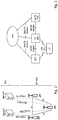
- the NG-RAN architecture is illustrated in Fig. 1 , based on TS 38.300 v. 15.0.0, section 4 incorporated herein by reference.
- the gNBs are interconnected with each other by means of the Xn interface.
- the gNBs are also connected by means of the Next Generation (NG) interface to the NGC (Next Generation Core), more specifically to the AMF (Access and Mobility Management Function) (e.g. a particular core entity performing the AMF) by means of the NG-C interface and to the UPF (User Plane Function) (e.g. a particular core entity performing the UPF) by means of the NG-U interface.
- NG Next Generation
- AMF Access and Mobility Management Function
- UPF User Plane Function
- a non-centralized deployment scenario (section 5.2 of TR 38.801; a centralized deployment is illustrated in section 5.4 incorporated herein by reference) is presented therein, where base stations supporting the 5G NR can be deployed.
- Fig. 2 illustrates an exemplary non-centralized deployment scenario and is based on Figure 5.2.-1 of said TR 38.801, while additionally illustrating an LTE eNB as well as a user equipment (UE) that is connected to both a gNB and an LTE eNB.
- the new eNB for NR 5G may be exemplarily called gNB.
- the URLLC use case has stringent requirements for capabilities such as throughput, latency and availability and has been envisioned as one of the enablers for future vertical applications such as wireless control of industrial manufacturing or production processes, remote medical surgery, distribution automation in a smart grid, transportation safety, etc.
- WID work item description
- RP-172115 it is agreed to support the ultra-reliability for URLLC by identifying the techniques to meet the requirements set by TR 38.913.
- key requirements include a target user plane latency of 0.5 ms for UL (uplink) and 0.5 ms for DL (downlink).
- the general URLLC requirement for one transmission of a packet is a BLER (block error rate) 1E-5 for a packet size of 32 bytes with a user plane of 1ms.
- NR URLLC in Rel. 15 should be capable of transmitting 32 bytes of data packet within a user-plane latency of 1ms at the success probability corresponding to a BLER of 1E-5.
- Augmented Reality/Virtual Reality (AR/VR) Augmented Reality/Virtual Reality
- e-health e-safety
- mission-critical applications see also ITU-R M.2083-0.
- technology enhancements targeted by NR URLCC in Release 15 aim at latency improvement and reliability improvement.
- Technology enhancements for latency improvement include configurable numerology, non slot-based scheduling with flexible mapping, grant free (configured grant) uplink, slot-level repetition for data channels, and downlink pre-emption.
- Pre-emption means that a transmission for which resources have already been allocated is stopped, and the already allocated resources are used for another transmission that has been requested later, but has lower latency / higher priority requirements. Accordingly, the already granted transmission is pre-empted by a later transmission.
- Pre-emption is applicable independent of the particular service type. For example, a transmission for a service-type A (URLCC) may be pre-empted by a transmission for a service type B (such as eMBB).
- Technology enhancements with respect to reliability improvement include dedicated CQI/MCS tables for the target BLER of 1E-5 (for the technology enhancements, see also 3GPP TS 38.211 “NR; Physical channels and modulation “, TS 38.212 “NR; Multiplexing and channel coding “, TS 38.213 “NR; Physical layer procedures for control “, and TS 38.214 “NR; Physical layer procedures for data “, respective versions V15.4.0, all incorporated herein by reference).
- mMTC uses a very large number of connected devices typically transmitting a relatively low volume of non-delay sensitive data.
- Devices are required to be low cost and to have a very long battery life. From NR perspective, utilizing very narrow bandwidth parts is one possible solution to have power saving from UE perspective and enable long battery life.
- the tighter requirements are higher reliability (up to 10-6 level), higher availability, packet sizes of up to 256 bytes, time synchronization down to the order of a few ⁇ s where the value can be one or a few ⁇ s depending on frequency range and short latency in the order of 0.5 to 1 ms in particular a target user plane latency of 0.5 ms, depending on the use cases (see also 3GPP TS 22.261 "Service requirements for next generation new services and markets" V16.4.0, incorporated herein by reference and RP-181477).
- PDCCH Physical Downlink Control Channel
- UCI Uplink Control Information
- HARQ Hybrid Automatic Repeat Request
- CSI feedback enhancements PUSCH enhancements related to mini-slot level hopping and retransmission/repetition enhancements.
- mini-slot refers to a Transmission Time Interval (TTI) including a smaller number of symbols than a slot (a slot comprising fourteen symbols).
- TTI determines the timing granularity for scheduling assignment.
- One TTI is the time interval in which given signals is mapped to the physical layer.
- the TTI length can vary from 14-symbols (slot-based scheduling) to 2-symbols (non-slot based scheduling).
- Downlink and uplink transmissions are specified to be organized into frames (10 ms duration) consisting of 10 subframes (1 ms duration).
- a subframe, in return is divided into slots, the number of slots being defined by the numerology / subcarrier spacing and the specified values range between 10 slots for a subcarrier spacing of 15 kHz to 320 slots for a subcarrier spacing of 240 kHz.
- the number of OFDM symbols per slot is 14 for normal cyclic prefix and 12 for extended cyclic prefix (see section 4.1 (general frame structure), 4.2 (Numerologies), 4.3.1 (frames and subframes) and 4.3.2 (slots) of the 3GPP TS 38.211 V15.4.0, incorporated herein by reference).
- assignment of time resources for transmission may also be non-slot based.
- the TTIs in non slot-based assignment may correspond to mini-slots rather than slots.
- one or more mini-slots may be assign to a requested transmission of data/control signaling.
- the minimum length of a TTI may conventionally be 2 OFDM symbols.
- enhancements are related to scheduling/HARQ/CSI processing timeline and to UL inter-UE Tx prioritization/multiplexing. Further identified are UL configured grant (grant free) transmissions, with focus on improved configured grant operation, example methods such as explicit HARQ-ACK, ensuring K repetitions and mini-slot repetitions within a slot, and other MIMO (Multiple Input, Multiple Output) related enhancements (see also 3GPP TS 22.261 V16.4.0).
- MIMO Multiple Input, Multiple Output
- the present disclosure is related to the potential layer 1 enhancements for further improved reliability/latency and for other requirements related to the use cases identified in (RP-181477, "New SID on Physical Layer Enhancements for NR URLLC", Huawei, HiSilicon, Nokia, Nokia Shanghai Bell). Specifically, enhancements for PUSCH (Physical Uplink Shared CHannel) repetition are discussed. The impact of the proposed ideas in this disclosure is expected to be on PUSCH repetition enhancements which is within the main scope of new SI (study items)/WI (work items) on NR URLLC in Rel. 16.
- One of the scopes for potential enhancements is related to mini-slot repetition of PUSCH within slot.
- a motivation for supporting repetition of PUSCH within a slot which may allow for potential enhancements to the repetition mechanism for further improving the reliability and/or latency to satisfy the new requirements of NR URLLC, is provided.
- one-shot transmission i.e. single (TTI) assignment
- TTI single (TTI) assignment
- the target BLER of 1E-6 is achieved with one-shot transmission. Therefore, retransmission or repetition mechanisms are required.
- HARQ-based retransmission is well known to improve the overall reliability, by using the feedback information and improving the subsequent retransmissions according to the channel conditions. However, they suffer from additional delay due to feedback processing timeline. Therefore, repetitions are useful for highly delay-tolerant services, as they do subsequent transmission of the same transport blocks without waiting for any feedback.
- a PUSCH repetition can be defined as "transmitting a same transport block more than once, without waiting for any feedback of previous transmission(s) of the same transport block".
- Advantages of PUSCH retransmissions are an improvement in the overall reliability and a reduction in latency in comparison with HARQ, as no feedback is required. However, in general, no link adaptation is possible, and resource usage may be inefficient.
- PUSCH mapping type A Such limited support of repetition is mainly useful for PUSCH mapping type A.
- This PUSCH mapping type A only allow PUSCH transmissions starting from the beginning of the slot. With repetitions, this would result in an initial PUSCH transmission and each repetition stating at the beginning of plural consecutive slots.
- PUSCH mapping type B allows PUSCH transmissions to start at any symbol within a slot. With repetitions, this would result in an initial PUSCH transmission and each repetition starting within a slot, at a same symbol of plural consecutive slots.
- such limited support may not be able to achieve stricter latency requirements in NR Rel. 15 i.e. up to 0.5 ms latency. This would require mini-slot repetitions. Additionally, the limited support of repetitions does also not exploit the benefits resulting from mini-slots, namely, transmission time intervals (TTIs) including a smaller number of symbols than a slot (a slot comprising fourteen symbols).
- TTIs transmission time intervals
- the more in flexibility shall not come at the expense of additional signaling overhead.
- the authors of the present disclosure have recognized that the flexible support of repetitions shall not require additional (dynamic) signaling scheduling each initial PUSCH transmission. Rather, the signaling mechanism, e.g. in form of downlink control information (DCI), shall stay the same, thereby avoiding any additional signaling overhead when scheduling the repetitions.
- DCI downlink control information
- transport block (TB) repetitions shall be supported with flexible timings which do not necessarily create additional signaling overhead.
- TB transport block
- Figure 4 shows an exemplary communication system including a user equipment (UE) 410 and a base station (BS) 460 in a wireless communication network.
- a communication system may be a 3GPP system such as NR and/or LTE and/or UMTS.
- the base station (BS) may be a gNB (gNodeB, e.g. an NR gNB) or an eNB (eNodeB, e.g. an LTE gNB).
- gNodeB e.g. an NR gNB
- eNodeB e.g. an LTE gNB
- the present disclosure is not limited to these 3GPP systems or to any other systems.
- a mobile terminal is referred to in the LTE and NR as a user equipment (UE).
- UE user equipment
- This may be a mobile device such as a wireless phone, smartphone, tablet computer, or an USB (universal serial bus) stick with the functionality of a user equipment.
- the term mobile device is not limited thereto, in general, a relay may also have functionality of such mobile device, and a mobile device may also work as a relay.
- a base station forms at least part of a system of interconnected units, for instance a (central) baseband unit and different radio frequency units, interfacing different antenna panels or radio heads in the network for providing services to terminals.
- a base station provides wireless access to terminals.
- the user equipment 410 comprises processing circuitry (or processor) 430 and a transmitter/ receiver (or transceiver) 420 which are indicated as separate building blocks in the diagram.
- base station 460 comprises processing circuitry (or processor) 480 and a transmitter/ receiver (or transceiver) 470, which are indicated as separate building blocks in the diagram.
- the transmitter/ receiver 420 of the user equipment 410 is communicatively coupled via a radio link 450 with the transmitter/ receiver 470 of the base station 460.
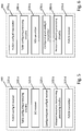
- FIGS. 5 and 6 depict exemplary implementations of the building blocks of the user equipment 410 and of the base station 460, respectively.
- the user equipment 410 of the exemplary implementation comprises a PUSCH config IE receiver 520-a, a table configuring processing circuitry 530-a, a DCI receiver 520-b, a configured grant config IE receiver 520-c, an allocated resources determining processing circuitry 530-b, and a PUSCH transmitter 520-d.
- the base station 460 of the exemplary implementation comprises a PUSCH config IE transmitter 570-a, a table configuring processing circuitry 580-a, a DCI transmitter 570-b, a configured grant config IE transmitter 570-c, a resource allocating processing circuitry 580-b, and PUSCH receiver 570-d.
- the present disclosure assumes that the user equipment 410 is in communication reach of the base station 460 and is configured with at least one bandwidth part in the downlink and at least one bandwidth part in the uplink.
- the bandwidth parts are located within the carrier bandwidth served by the base station 460.
- the present disclosure assumes that the user equipment 410 is operating in a radio resource control, RRC, connected state (termed: RRC_CONNECTED), thereby capable of receiving in the downlink data and/or control signals from the base station 460 and capable of transmitting in the uplink data and/or control signals to the base station 460.
- RRC radio resource control
- the user equipment 410 Before performing PUSCH repetitions as suggested in the present disclosure, the user equipment 410 receives control messages as defined in the radio resource control, RRC, and the medium access control, MAC, protocol layer. In other words, the user equipment 410 employs signaling mechanism which is readily available in the different protocol layers of the various communication technologies.
- RRC radio resource control
- MAC medium access control
- RRC control messages are usually used for configuration of radio resources (e.g. radio link) on a semi-static basis whereas MAC control messages are used for dynamically defining each medium access (e.g. transmission) separately. From this, it directly follows that RRC control occurs less frequently than MAC control.
- an excessive MAC control signaling overhead can substantially impair the communication system performance whereas the RRC control message have been treated more leniently in standardization.
- MAC control signaling overhead is a well-recognized constraint to the system performance.
- transport block is to be understood as data unit of an uplink and/or downlink transmission.
- transport block is equivalent to a MAC layer packed data unit, PDU.
- the transmission of transport block is equally understood as a physical uplink shared channel (PUSCH) and/or physical downlink shared channel (PDSCH) transmission.
- PUSCH physical uplink shared channel
- PDSCH physical downlink shared channel
- PUSCH and/or PDSCH transmissions generally carry payload
- the present disclosure shall refer to PUSCH and/or PDSCH transmissions carrying a MAC PDU.
- the terms "PUSCH and/or PDSCH transmissions" shall be understood as describing MAC PDU transmission on PUSCH and/or PDSCH.
- a generic scenario is described with regard to performing PUSCH repetitions based on a dynamic grant, namely a DCI carrying a time-domain resource assignment filed, such as, for example, a DCI of DCI format 0-0 or of DCI format 0-1.
- the receiver 420 of the user equipment 410 receives (see e.g. step 710 - Fig. 7 ) a physical uplink shared channel, PUSCH, config information element, IE.
- This PUSCH config IE is received in form of radio resource control, RRC, signaling and applicable to a particular bandwidth part.
- the PUSCH config IE is received from the base station 460 serving the particular bandwidth part. For example, this reception operation may be performed by the PUSCH config IE receiver 520-a of Fig. 5 .
- the PUSCH config IE carries among others a list of parameters in form of an information element (IE) termed "PUSCH-TimeDomainResourceAllocationList", wherein each parameter of the list of parameters is termed "PUSCH-TimeDomainResourceAllocation”.
- the processor 430 of the user equipment 410 configures (see e.g. step 720 - Fig. 7 ) a table which is defined by the PUSCH time domain resource allocation list IE carried in the received PUSCH config IE.
- the table comprises rows, each with a value indicating a PUSCH mapping type, a value K 2 indicating a slot offsets, and a value SLIV indicating a start and length indicator.
- this configuration operation may be performed by the table configuring processing circuitry 520-a of Fig. 5 .
- each row of the RRC configure table corresponds to one of plural parameters termed "PUSCH-TimeDomainResourceAllocation" of the list of parameters termed "PUSCH-TimeDomainResourceAllocationList”.
- PUSCH-TimeDomainResourceAllocationList the list of parameters termed "PUSCH-TimeDomainResourceAllocationList”.
- the RRC configured table in its entirety is defined by the PUSCH time domain resource allocation list IE.
- the receiver 420 of the user equipment 410 receives (see e.g. step 730 - Fig. 7 ) downlink control information, DCI, in form of medium access control, MAC, signaling.
- DCI downlink control information
- the DCI is carrying a time-domain resource assignment filed with value m, wherein the value m provides a row index m+1 to the configured table.
- this reception operation may be performed by the DCI receiver 520-b of Fig. 5 .
- this DCI is carrying an uplink grant since it serves the purpose of triggering PUSCH repetitions.
- the received DCI is in DCI format 0-0 or in DCI format 0-1.
- the described scenario refers to situation where the PUSCH repetitions are scheduled by a dynamic grant.
- the processor 430 of the user equipment 410 determines allocated resources for an initial PUSCH transmission and also allocated resources for at least one repetition of the initial PUSCH transmission.
- the following description focusses on the allocation of resources in time domain. For example, this determination operation may be performed by the allocated resources determining processing circuitry 530-b of Fig. 5 .
- the resources to be used by the user equipment 410 for the initial PUSCH transmission and the repetition(s) thereof have been previously allocated by the base station 460.
- the processor 430 accordingly determines which of the previously allocated resource it shall use for the PUSCH transmission and the repetition(s) thereof.
- the processor 430 at first determines (see e.g. step 740 - Fig. 7 ) the allocated resources for the initial PUSCH transmission based on: (i) a number of a slot carrying the received DCI, and (ii) the value K 2 indicating the slot offsets, and (iii) the value SLIV indicating the start and length indicator comprised in indexed row of the RRC configured table. This implies that the processor 430 has previously determined that the value indicating the PUSCH mapping type indicates a type B mapping.
- the processor determines that the allocated resources, for the initial PUSCH transmission, are included in a slot with a number of k+ K 2 , and have a start and length in terms of symbols of this slot corresponding to the value SLIV.
- the processor 430 When determining the allocated resources, the processor 430 also uses the value indicating the PUSCH mapping type additionally comprised in the row of the RRC configured table with row index m+1. Particularly, in case the value indicates a type A PUSCH mapping, the processor 430 only uses the length of the value SLIV indicating a start and length indicator. In case the value indicates a type B PUSCH mapping, the processor 430 uses both the start and the length of the value SLIV indicating the start and length indicator.
- the processor 430 determines allocated resources for the at least one repetition of the initial PUSCH transmission. For this, the processor 430 checks (see e.g. step 750 - Fig. 7 ) if there is an (explicit) time domain resource assignment related to parameters (e.g. the timing) for the repetition. For this, the processor 430 reverts to the row with row index m+1 and checks whether or not this row comprises additional values (e.g. at least one value) which are specifying the allocated resource in time domain for the at least one repetition of the initial PUSCH transmission.
- additional values e.g. at least one value
- the processor 430 uses (see e.g. step 760 - Fig. 7 ) a conventional slot-based repetition mechanism for the repetition of the initial PUSCH transmission.
- the processor 430 relies on pre-specified (e.g. in the relevant standard fixedly prescribed) timing relations between the initial PUSCH transmission and the repetitions thereof. For example, this results in an initial PUSCH transmission and each repetition starting at a same symbol and having a same symbol length of plural consecutive slots.
- the processor 430 for the at least one repetition, reverts to the row with row index m+1 of the RRC configured table, and determines that the allocated resources, for the first repetition of the initial PUSCH transmission, are included in a slot with number k+ K 2 +1 (where 1 is a pre-defined constant fixed by standardization), and have a start and length in terms of symbols of this slot corresponding to the same value SLIV.
- the processor 430 that the allocated resources, for the second repetition of the initial PUSCH transmission, are included in a slot with number k+ K 2 +2 (where 2 is again a pre-defined constant fixed by standardization), and have a start and length in terms of symbols of this slot corresponding to the same value SLIV as already the initial PUSCH transmission and the first repetition thereof. Further repetitions follow at contiguous slots.
- the processor 430 determines that each one of the initial, the first repetition and the second repetition of the PUSCH transmission have resources corresponding to symbol 4, symbol 5, symbol 6 and symbol 7 in the slots with number k+ K 2 , number k+ K 2 +1, number k+ K 2 +2, respectively.
- the processor 430 uses (see e.g. step 770 - Fig. 7 ) the additional values (e.g. at least one value) comprised in the indexed row of the RRC configure table for determining allocated resources for the repetition of the initial PUSCH transmission.
- the comprised at least one additional value is specifying the allocated resource in time domain for the repetition of the initial PUSCH transmission.
- the at least one additional value is comprised in a row of the RRC configured table which is defined by the PUSCH time domain resource allocation list IE.
- the at least one additional value comprised therein is defined by the PUSCH time domain resource allocation list IE.
- the at least one additional value could be (directly) prescribed by a parameter comprised in the PUSCH time domain resource allocation list IE, or alternatively the at least one additional value could be (indirectly) inferred from related parameters comprised in the PUSCH time domain resource allocation list IE. In any case, the at least one additional value specifies in time domain the repetition of the initial PUSCH transmission.
- processor 430 of the user equipment 410 uses additional values from the indexed row of the RRC configured table for determining the allocated resources for the repetitions. This approach substantially differs from the conventional slot-based repetition mechanism for the following reasons:
- this permits increasing flexibility while avoiding signaling overhead, namely by the processor 430 of the user equipment 410 using the at least one additional value from the indexed row of the RRC configured table for determining the allocated resources for the repetitions.
- the transmitter 420 of the user equipment 410 transmits (not depicted in Fig. 7 ) a PUSCH transmission using the respectively determined allocated resources for the initial PUSCH transmission and for the at least one repetition thereof.
- this transmission operation may be performed by the PUSCH transmitter 520-d of Fig. 5 .
- the above description has been given from the perspective of the user equipment 410. This shall, however, not be understood as a limitation to the present disclosure.
- the base station 460 equally performs the generic scenario disclosed herein.
- the transmitter 470 of the base station 460 transmits a physical uplink shared channel, PUSCH, config information element, IE, in form of radio resource control, RRC, signalling.
- PUSCH physical uplink shared channel
- IE config information element
- RRC radio resource control
- the PUSCH config IE being applicable to a particular bandwidth part. For example, this transmission operation may be performed by the PUSCH config IE transmitter 670-a of Fig. 6 .
- the processor 480 of the base station 460 configures a table which is defined by a PUSCH time domain resource allocation list IE carried in the received PUSCH config IE.
- the RRC configured table comprises rows, each with a value indicating a PUSCH mapping type, a value K 2 indicating a slot offsets, and a value SLIV indicating a start and length indicator.
- this configuration operation may be performed by the table configuring processing circuitry 680-a of Fig. 6 .
- the transmitter 470 of the base station 460 transmits downlink control information, DCI, in form of medium access control, MAC, signalling carrying a time-domain resource assignment filed with value m, wherein the value m provides a row index m+1 to the RRC configured table.
- DCI downlink control information
- MAC medium access control
- the processor 480 of the base station 460 allocates resources for an initial PUSCH transmission and allocates resources for at least one repetition thereof based on: (i) a number of a slot carrying the transmitted DCI, and (ii) the value K 2 indicating the slot offsets, and (iii) the value SLIV indicating the start and length indicator comprised in indexed row of the RRC configured table.
- the determination of allocated resources is based on at least one additional value comprised in the indexed row of the RRC configured table which is specifying the allocated resources in time domain for the at least one repetition of the initial PUSCH transmission.
- this resource allocation operation may be performed by the resource allocating processing circuitry 680-b of Fig. 6 .
- a receiver 470 of the base station 460 receives a PUSCH transmission using the respectively allocated resources for the initial PUSCH transmission and for the at least one repetition thereof. For example, this reception operation may be performed by the PUSCH receiver 670-d of Fig. 6 .
- the receiver 420 of the user equipment 410 receives a physical uplink shared channel, PUSCH, config information element, IE, in form of radio resource control, RRC, signalling.
- the PUSCH config IE is applicable to a particular bandwidth part.
- the PUSCH config IE is received from the base station 460 serving the particular bandwidth part. For example, the reception operation may be performed by the PUSCH config IE receiver 520-a of Fig. 5 .
- the processor 430 of the user equipment 410 configures a table which is defined by a PUSCH time domain resource allocation list IE carried in the received PUSCH config IE.
- the RRC configured table comprises rows, each with a value indicating a PUSCH mapping type, a value K 2 indicating a slot offset, and a value SLIV indicating a start and length indicator.
- this configuration operation may be performed by the table configuring processing circuitry 530-a of Fig. 5 .
- the receiver 420 of the user equipment 410 receives a configured grant config IE in form of RRC signalling carrying a time domain allocation filed with value m, wherein the value m provides a row index m+1 to the configured table.
- this reception operation may be performed by the configured grant config IE receiver 520-c of Fig. 5 .
- the processor 430 of the user equipment 410 determines allocated resources for an initial PUSCH transmission and allocated resources for at least one repetition thereof based on: (i) a value of time domain offset field additionally carried in the received configured grant config IE and associated with the time domain allocation filed, and (ii) the value K 2 indicating the slot offsets, and (iii) the value SLIV indicating the start and length indicator comprised in indexed row of the RRC configured table.
- the determination of allocated resources is based on at least one additional value comprised in the indexed row of the RRC configured table which is specifying the allocated resources in time domain for the at least one repetition of the initial PUSCH transmission.
- this determination operation may be performed by the allocated resources determining processing circuitry 530-b.
- the transmitter 420 of the user equipment 410 transmits a PUSCH transmission using the respectively determined allocated resources for the initial PUSCH transmission and for the at least one repetition thereof.
- this transmission operation may be performed by the PUSCH transmitter 530-d of Fig. 5 .
- the above description has been given from the perspective of the user equipment 410. This shall, however, not be understood as a limitation to the present disclosure.
- the base station 460 equally performs the generic scenario disclosed herein.
- the transmitter 470 of the base station 460 transmits a physical uplink shared channel, PUSCH, config information element, IE, in form of radio resource control, RRC, signalling, the PUSCH config IE being applicable to a particular bandwidth part.
- this transmission operation may be performed by the PUSCH config IE transmitter 670-a of Fig. 6
- the processor 480 of the base station 460 configures a table which is defined by a PUSCH time domain resource allocation list IE carried in the received PUSCH config IE.
- the RRC configured table comprises rows, each with a value indicating a PUSCH mapping type, a value K 2 indicating a slot offsets, and a value SLIV indicating a start and length indicator.
- this configuration operation may be performed by the table configuring processing circuitry 680-a of Fig. 6 .
- the transmitter 470 of the base station 460 transmits a configured grant config IE in form of RRC signalling carrying a time domain allocation filed with value m, wherein the value m provides a row index m+1 to the RRC configured table.
- this transmission operation may be performed by the configured grant config IE transmitter 670-c of Fig. 6 .
- the processor 480 of the base station 460 allocates resources for an initial PUSCH transmission and allocates resources for at least one repetition thereof based on: (i) a value of time domain offset field additionally carried in the received configured grant config IE and associated with the time domain allocation filed, and (ii) the value K 2 indicating the slot offsets, and (iii) the value SLIV indicating the start and length indicator comprised in indexed row of the RRC configured table.
- the determination of allocated resources is based on at least one additional value comprised in the indexed row of the RRC configured table which is specifying the allocated resources in time domain for the at least one repetition of the initial PUSCH transmission.
- this resource allocation operation may be performed by the resource allocating processing circuitry 680-b of Fig. 6 .
- the receiver 470 of the base station 460 receives a PUSCH transmission using the respectively determined allocated resources for the initial PUSCH transmission and for the at least one repetition thereof. For example, this reception operation may be performed by the PUSCH receiver 670-d of Fig. 6 .
- transport block (TB) repetitions in the uplink but can equally be applied to downlink transmissions, namely to achieve a flexible support of repetitions in the downlink. Also here, transport block (TB) repetitions are supported with flexible timings which do not create additional signaling overhead.
- the benefit of an improved flexibility when scheduling transport block repetitions are not only achievable for physical uplink shared channel (PUSCH) transmissions, but are equally achievable for physical downlink shared channel (PDSCH) transmissions.
- PUSCH physical uplink shared channel
- PDSCH physical downlink shared channel
- the receiver 420 of the user equipment 410 receives a physical downlink shared channel, PDSCH, config information element, IE, in form of radio resource control, RRC, signalling.
- PDSCH physical downlink shared channel
- IE config information element
- RRC radio resource control
- the processor 430 of the user equipment 410 configures a table which is defined by a PDSCH time domain resource allocation list IE carried in the received PDSCH config IE.
- the RRC configured table comprising rows, each with a value indicating a PDSCH mapping type, a value K 2 indicating a slot offsets, and a value SLIV indicating a start and length indicator.
- the receiver 420 of the user equipment 410 receives downlink control information, DCI, in form of medium access control, MAC, signalling carrying a time-domain resource assignment filed with value m, wherein the value m provides a row index m+1 to the RRC configured table.
- DCI downlink control information
- MAC medium access control
- the processor 430 of the user equipment 410 determines allocated resources for an initial PDSCH transmission and allocated resources for at least one repetition thereof based on: (i) a number of a slot carrying the received DCI, and (ii) the value K 2 indicating the slot offsets, and (iii) the value SLIV indicating the start and length indicator comprised in indexed row of the RRC configured table.
- the determination of allocated resources is based on at least one additional value comprised in the indexed row of the RRC configured table which is specifying the allocated resources in time domain for the at least one repetition of the initial PDSCH transmission.
- the receiver 420 of the user equipment 410 receives a PDSCH transmission using the respectively determined allocated resources for the initial PDSCH transmission and for the at least one repetition thereof.
- the at least one additional value is at least one of a value K 2 ' indicating a second slot offset for the at least one repetition, a value SLIV' indicating a second start and length indicator value for the at least one repetition, and optionally a value indicating the number of the at least one repetition.
- the second start and length indicator value SLIV' comprises: a value S' indicating a symbol number specifying the start of the allocated resources for the at least one repetition, and a value L' indicating a number of symbols specifying the length of the allocated resources for the at least one repetition.
- the RRC configured table comprises not only values which are specifying allocated resources for the initial PUSCH transmission. Rather the RRC configured table comprises additional values K 2 ' and/or SLIV' which are specifying allocated resources for the repetition of the initial PUSCH transmission.
- the optional additional value indicating the number of the least one repetition further complements the RRC configured table in that it permits a more flexible determination as to which of the specified allocated resource are to be used for repetitions.
- the RRC configured table comprises rows, each with a value indicating a PUSCH mapping type, a value K 2 indicating a slot offsets for the initial PUSCH transmission, a value SLIV indicating a start and length indicator for the initial PUSCH transmission, as additional values, a value K 2 ' indicating a second slot offset for the at least one repetition, a value SLIV' indicating a second start and length indicator value for the at least one repetition.
- Table 1 DCI Row index PUSCH mapping type K2 S L ⁇ K2' ⁇ , ⁇ S' ⁇ , ⁇ L' ⁇ 1
- Type A K2_1 S_1 L_1 ⁇ K2'_1_1, K2'_1_2,....K2'_1_n ⁇ , ⁇ S2'_1_1, S2'_1_2,....S2'_1_n ⁇ , ⁇ L2'_1_1, L2'_1_2,....L2'_1_n ⁇ 2
- Type B K2_2 S_2 L_2 ⁇ K2'_2_1, K2'_2_2,....K2'_2_n ⁇ , ⁇ S2'_2_1, S2'_2_2,....S2'_2_n), ⁇ L2'_2_1, L2'_2_2,....L2_2_n ⁇ .... .... .... 16 .... .... .... .... ...
- the values SLIV and SLIV' are each shown to comprise: a value S and S' indicating a symbol number specifying the start of the allocated resources, and a value L and L' indicating a number of symbols specifying the length of the allocated resources.
- the RRC configured table not only comprises one set of additional values K 2 ' and SLIV', or better K 2 ', S' and L', but instead comprises such a set of additional values for each of the PUSCH repetitions to be transmitted by the user equipment 410. This achieves a high degree of flexibility for each of the PUSCH repetitions without creating additional signaling overhead.
- the processor 430, 480 of the user equipment 410, or of the base station 460 configures this table in accordance with the parameters comprised in a PUSCH time domain resource allocation list IE, namely with the list of parameters termed PUSCH time domain resource allocation.
- the table is defined by the PUSCH time domain resource allocation list IE as carried in the PUSCH config IE received in form of RRC signaling.
- PUSCH time domain resource allocation list IE An example of such a PUSCH time domain resource allocation list IE is reproduced herein below, namely as example 1. As the terminology may change in the future, this example shall be more broadly understood with regard to its functions and concepts of signaling the additional parameters comprised in a PUSCH time domain resource allocation list IE.
- Example 1 ASN.1 notation of "PUSCH-TimeDomainResourceAllocationList IE"
- the PUSCH time domain resource allocation parameter includes not only values indicating a PUSCH mapping type, a value K 2 indicating a slot offsets for the initial PUSCH transmission, a value SLIV indicating a start and length indicator for the initial PUSCH transmission, but also a value indicating the number of repetitions (termed number of resource indicator value, RIV, assignments), and for each of the repetitions (termed RIV assignments), a value K 2 ' indicating a second slot offset for the at least one repetition, a value SLIV' indicating a second start and length indicator value for the at least one repetition.
- the value indicating the number of repetitions (termed number of RIV assignments) of the IE is only indirectly reflected in the RRC configured table, namely in form of the total number of each of the values K 2 ', S' and L'. This value may, however, also be directly included in the RRC configured table.
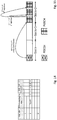
- FIG. 8- 9 One usage of the RRC configured table of the first exemplary implementation is depicted in Figs. 8- 9 where an exemplary RRC configured table for PUSCH repetitions is given and corresponding resource allocations in time domain are shown according to a usage of a first exemplary implementation.
- the RRC configured table in a row with row index 3, values are given for which corresponding resource allocations in time domain are shown.
- the RRC configured table comprises, in the row with the row index 3, a value indicating the PUSCH mapping type to be type b, meaning that resource allocations may start within the slot and are not necessarily starting at the beginning of the slot.
- this row comprises a value K 2 indicating that allocated resources for the initial PUSCH transmission is included in the slot with slot number k+2.
- values S and L are comprised indicating that the allocated resources for the initial PUSCH transmission start in the slot with slot number k+2 at the symbol with symbol number 1 and have a length of 4 symbols.
- this row comprises two additional values K 2 ' indicating that the allocated resources for the first and second repetition of the initial PUSCH transmission are included in slots relative to the value k corresponding to the number of the slot carrying the received DCI, or corresponding to the value of time domain offset field additionally carried in the received configured grant config IE.
- the allocated resources for the first and second repetition are included in the slots with slot numbers k+2 and k+3, respectively.
- two values S' and two values L' are comprised indicating that the allocated resources for the first and second repetition of the initial PUSCH transmission start in the respective slot with slot number k+2 and k+3 at the symbol with symbol numbers 6 and 1, respectively.
- the respective resource allocations in time domain are also shown.
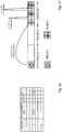
- FIG. 10- 11 Another usage of the RRC configured table of the first exemplary implementation is depicted in Figs. 10- 11 where an exemplary RRC configured table for PUSCH repetitions is given and corresponding resource allocations in time domain are shown according to a usage of a first exemplary implementation.
- the RRC configured table in a row with row index 3, values are given for which corresponding resource allocations in time domain are shown.
- the RRC configured table comprises, in the row with the row index 3, a value indicating the PUSCH mapping type to be type b, meaning that resource allocations may start within the slot and are not necessarily starting at the beginning of the slot.
- this row comprises a value K 2 indicating that allocated resources for the initial PUSCH transmission is included in the slot with slot number k+2.
- values S and L are comprised indicating that the allocated resources for the initial PUSCH transmission start in the slot with slot number k+2 at the symbol with symbol number 1 and have a length of 4 symbols.
- this row comprises two additional values K 2 ' indicating that the allocated resources for both, the first and second repetition of the initial PUSCH transmission are included in slots relative to the number of the slot k+2 with the allocated resources for the initial PUSCH transmission.
- the allocated resources for the first and second repetition are included in the slots with slot numbers (k+2)+0 and (k+2)+1, respectively.
- two values S' and two values L' are comprised indicating that the allocated resources for the first and second repetition of the initial PUSCH transmission start in the respective slot with slot number (k+2)+0 and (k+2)+1 at the symbol with symbol numbers 6 and 1, respectively.
- the respective resource allocations in time domain are also shown.
- FIG. 12- 13 Another usage of the RRC configured table of the first exemplary implementation is depicted in Figs. 12- 13 where an exemplary RRC configured table for PUSCH repetitions is given and corresponding resource allocations in time domain are shown according to a usage of a first exemplary implementation.
- the RRC configured table in a row with row index 3, values are given for which corresponding resource allocations in time domain are shown.
- the RRC configured table comprises, in the row with the row index 3, a value indicating the PUSCH mapping type to be type b, meaning that resource allocations may start within the slot and are not necessarily starting at the beginning of the slot.
- this row comprises a value K 2 indicating that allocated resources for the initial PUSCH transmission is included in the slot with slot number k+2.
- values S and L are comprised indicating that the allocated resources for the initial PUSCH transmission start in the slot with slot number k+2 at the symbol with symbol number 1 and have a length of 4 symbols.
- this row comprises two additional values K 2 ' indicating that the allocated resources for the first repetition of the initial PUSCH transmission is included in the slots relative to the number of the slot k+2 with the allocated resources for the initial PUSCH transmission, and the second repetition is included in the slot relative to the number of the slot (k+2)+0 with the allocated resources for the first repetition.
- the allocated resources for the first and second repetition are included in the slots with slot numbers (k+2)+0 and ((k+2)+0)+1, respectively.
- two values S' and two values L' are comprised indicating that the allocated resources for the first and second repetition of the initial PUSCH transmission start in the respective slot with slot number (k+2)+0 and ((k+2)+0)+1 at the symbol with symbol numbers 6 and 1, respectively.
- the respective resource allocations in time domain are also shown.
- the second slot offset specifies the allocated resources for a subsequent one of the at least one repetition relative to a number of a slot with the allocated resources for a preceding one of the at least one repetition.
- the at least one additional value is at least one of a value G' indicating a number of symbols of a gap before the allocated resources for the at least one repetition, a value L' indicating a number of symbols specifying the length of the allocated resources for the at least one repetition, and optionally a value indicating the number of the at least one repetition.
- the RRC configured table comprises not only values which are specifying allocated resources for the initial PUSCH transmission. Rather the RRC configured table comprises additional values G' and/or L' which are specifying allocated resources for the repetition of the initial PUSCH transmission.
- the optional additional value indicating the number of the least one repetition may further complement the RRC configured table in that it permits a more flexible determination which of the specified allocated resource are to be used for repetitions.
- the RRC configured table not only comprises one set of additional values G' and L' but instead comprises one additional value L' which is applicable to all repetitions, and a set of additional values G' for each of the PUSCH repetitions to be transmitted by the user equipment 410. This achieves a high degree of flexibility for each of the PUSCH repetitions without creating additional signaling overhead.
- the processor 430, 480 of the user equipment 410, or of the base station 460 configures this table in accordance with the parameters comprised in a PUSCH time domain resource allocation list IE, namely with the list of parameters termed PUSCH time domain resource allocation.
- the table is defined by the PUSCH time domain resource allocation list IE as carried in the PUSCH config IE received in form of RRC signaling.
- Example 2 ASN.1 notation of "PUSCH-TimeDomainResourceAllocationList IE"
- the PUSCH time domain resource allocation parameter includes not only values indicating a PUSCH mapping type, a value K 2 indicating a slot offsets for the initial PUSCH transmission, a value SLIV indicating a start and length indicator for the initial PUSCH transmission, but also a value L' (termed length of each repetition) indicating the length in number of symbols of each repetition, a value indicating the number of repetitions (termed number of repetitions), and for each of the repetitions (termed repetition gap), a value G' indicating a number of symbols of a gap before the allocated resources for the at least one repetition.
- the value indicating the number of repetitions (termed number of repetitions) of the IE is only indirectly reflected in the RRC configured table, namely in form of the total number of the values G'. This value may, however, also be directly included in the RRC configured table.
- FIG. 14- 15 One usage of the RRC configured table of the second exemplary implementation is depicted in Figs. 14- 15 where an exemplary RRC configured table for PUSCH repetitions is given and corresponding resource allocations in time domain are shown according to a usage of a second exemplary implementation.
- the RRC configured table in a row with row index 3, values are given for which corresponding resource allocations in time domain are shown.
- the RRC configured table comprises, in the row with the row index 3, a value indicating the PUSCH mapping type to be type b, meaning that resource allocations may start within the slot and are not necessarily starting at the beginning of the slot.
- this row comprises a value K 2 indicating that allocated resources for the initial PUSCH transmission is included in the slot with slot number k+2.
- values S and L are comprised indicating that the allocated resources for the initial PUSCH transmission start in the slot with slot number k+2 at the symbol with symbol number 1 and have a length of 4 symbols.
- this row comprises one additional value L' indicating the length in number of symbols is 4 for the allocated resources of each of the first and second repetition, and two additional values G' indicating that the allocated resources for the first and second repetition of the initial PUSCH transmission start at a symbol with a gap G' of a number of symbols 1, 6 before the allocated resources.
- the number of symbols of the gap indicated by value G' is relative to a number 4 of a last symbol within slot k+2 of the allocated resources for the initial PUSCH transmission.
- the allocated resources for the first and second repetition are included in the slots with slot numbers k+2.
- the number of the last symbol of the allocated resources of the initial PUSCH transmission is 4.
- a gap of 1 symbol determines the allocated resources for the first repetition to start at symbol number 4+1 and to end at symbol number 4+1+4.
- a gap of 6 symbols determines the allocated resources for the second repetition to start at symbol 4+6 and to end at symbol number 4+6+4.
- the respective resource allocations in time domain are also shown.
- FIG. 16- 17 Another usage of the RRC configured table of the second exemplary implementation is depicted in Figs. 16- 17 where an exemplary RRC configured table for PUSCH repetitions is given and corresponding resource allocations in time domain are shown according to another usage of a second exemplary implementation.
- the RRC configured table in a row with row index 3, values are given for which corresponding resource allocations in time domain are shown.
- the RRC configured table comprises, in the row with the row index 3, a value indicating the PUSCH mapping type to be type b, meaning that resource allocations may start within the slot and are not necessarily starting at the beginning of the slot.
- this row comprises a value K 2 indicating that allocated resources for the initial PUSCH transmission is included in the slot with slot number k+2.
- values S and L are comprised indicating that the allocated resources for the initial PUSCH transmission start in the slot with slot number k+2 at the symbol with symbol number 1 and have a length of 4 symbols.
- this row comprises one additional value L' indicating the length in number of symbols is 4 for the allocated resources of each of the first and second repetition, and two additional values G' indicating that the allocated resources for the first and second repetition of the initial PUSCH transmission start at a symbol with a gap of a number of symbols 1, 6 before the allocated resources.
- the number of symbols of the gap indicated by value G' is relative to a number 4 of a last symbol within slot k+2 of the allocated resources for the initial PUSCH transmission.
- the number of the symbols of the gap indicated by value G' is relative to the number 4+1+4 of a last symbol of the slot k+2 of the allocated resource for the first repetition.
- the allocated resources for the first and second repetition are included in the slots with slot numbers k+2.
- the number of the last symbol of the allocated resources of the initial PUSCH transmission is 4.
- a gap of 1 symbol determines the allocated resources for the first repetition to start at symbol number 4+1 and to end at symbol number 4+1+4.
- a gap of 1 symbols determines the allocated resources for the second repetition to start at symbol 4+1+4+1 and to end at symbol number 4+1+4+1+4.
- the number of symbols of the gap specifies the allocated resources for a subsequent one of the at least one repetition relative to a number of a last symbol of the allocated resources for a preceding one of the at least one repetition.
- the at least one additional value is at least one of a value G' indicating a number of symbols of a gap before the allocated resources for the at least one repetition, a value L' indicating a number of symbols specifying the length of the allocated resources for the at least one repetition, and optionally a value indicating the number of the at least one repetition.
- the RRC configured table comprises not only values which are specifying allocated resources for the initial PUSCH transmission. Rather the RRC configured table comprises additional values G' and/or L' which are specifying allocated resources for the repetition of the initial PUSCH transmission.
- the optional additional value indicating the number of the least one repetition may further complement the RRC configured table in that it permits a more flexible determination as to which of the specified allocated resource are to be used for repetitions.
- Table 3 DCI Row index PUSCH mapping type K2 S L ⁇ L' ⁇ , ⁇ G ⁇ 1 Type A K2_1 S_1 L_1 ⁇ L_1_1,L'_1_2....L'_1_n1 ⁇ , ⁇ G_1_1, G_1_2....G_1_n1 ⁇ 2 Type B K2_2 S_2 L_2 ⁇ L'_2_1,L'_2_2....L'_2_n2 ⁇ , ⁇ G_2_1, G_2_2....G_2_n2 ⁇ .... .... .... .... .... .... .... .... .... .... .... ....
- the RRC configured table not only comprises one set of additional values G' and L' but instead comprises a set of additional values G' and L' for each of the PUSCH repetitions to be transmitted by the user equipment 410. This achieves a high degree of flexibility for each of the PUSCH repetitions without creating additional signaling overhead.
- the processor 430, 480 of the user equipment 410, or of the base station 460 configures this table in accordance with the parameters comprised in a PUSCH time domain resource allocation list IE, namely with the list of parameters termed PUSCH time domain resource allocation.
- the table is defined by the PUSCH time domain resource allocation list IE as carried in the PUSCH config IE received in form of RRC signaling.
- Example 3 ASN.1 notation of "PUSCH-TimeDomainResourceAllocationList IE"
- the PUSCH time domain resource allocation parameter includes not only values indicating a PUSCH mapping type, a value K 2 indicating a slot offsets for the initial PUSCH transmission, a value SLIV indicating a start and length indicator for the initial PUSCH transmission, but also a value indicating the number of repetitions (termed number of repetitions), and for each of the repetitions (termed repetition gap), a value L' (termed length of each repetition) indicating the length in number of symbols of each repetition, and a value G' indicating a number of symbols of a gap before the allocated resources for the at least one repetition.
- the value indicating the number of repetitions (termed number of repetitions) of the IE is only indirectly reflected in the RRC configured table, namely in form of the total number of each of the values G' and L'. This value may, however, also be directly included in the RRC configured table.
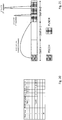
- FIG. 18- 19 One usage of the RRC configured table of the third exemplary implementation is depicted in Figs. 18- 19 where an exemplary RRC configured table for PUSCH repetitions is given and corresponding resource allocations in time domain are shown according to a usage of a second exemplary implementation.
- the RRC configured table in a row with row index 3, values are given for which corresponding resource allocations in time domain are shown.
- the RRC configured table comprises, in the row with the row index 3, a value indicating the PUSCH mapping type to be type b, meaning that resource allocations may start within the slot and are not necessarily starting at the beginning of the slot.
- this row comprises a value K 2 indicating that allocated resources for the initial PUSCH transmission is included in the slot with slot number k+2.
- values S and L are comprised indicating that the allocated resources for the initial PUSCH transmission start in the slot with slot number k+2 at the symbol with symbol number 1 and have a length of 4 symbols.
- this row comprises two additional value L' indicating the length in number of symbols 4, 3 for the allocated resources of the first and second repetition, and two additional values G' indicating that the allocated resources, for the first and second repetition of the initial PUSCH transmission, start at a symbol with a gap G' of a number of symbols 1, 6 before the allocated resources.
- the number of symbols of the gap indicated by value G' is relative to a number 4 of a last symbol within slot k+2 of the allocated resources for the initial PUSCH transmission.
- the allocated resources for the first and second repetition are included in the slots with slot numbers k+2.
- the number of the last symbol of the allocated resources of the initial PUSCH transmission is 4.
- a gap of 1 symbol determines the allocated resources for the first repetition to start at symbol number 4+1 and to end at symbol number 4+1+4.
- a gap of 6 symbols determines the allocated resources for the second repetition to start at symbol 4+6 and to end at symbol number 4+6+3.
- the respective resource allocations in time domain are also shown.
- FIG. 20- 21 Another usage of the RRC configured table of the second exemplary implementation is depicted in Figs. 20- 21 where an exemplary RRC configured table for PUSCH repetitions is given and corresponding resource allocations in time domain are shown according to another usage of a second exemplary implementation.
- the RRC configured table in a row with row index 3, values are given for which corresponding resource allocations in time domain are shown.
- the RRC configured table comprises, in the row with the row index 3, a value indicating the PUSCH mapping type to be type b, meaning that resource allocations may start within the slot and are not necessarily starting at the beginning of the slot.
- this row comprises a value K 2 indicating that allocated resources for the initial PUSCH transmission is included in the slot with slot number k+2.
- values S and L are comprised indicating that the allocated resources for the initial PUSCH transmission start in the slot with slot number k+2 at the symbol with symbol number 1 and have a length of 4 symbols.
- this row comprises two additional value L' indicating the length in number of symbols 4, 3 for the allocated resources of the first and second repetition, and two additional values G' indicating that the allocated resources, for the first and second repetition of the initial PUSCH transmission, start at a symbol with a gap G' of a number of symbols 1, 6 before the allocated resources.
- the number of symbols of the gap indicated by value G' is relative to a number 4 of a last symbol within slot k+2 of the allocated resources for the initial PUSCH transmission.
- the number of the symbols of the gap indicated by value G' is relative to the number 4+1+4 of a last symbol of the slot k+2 of the allocated resource for the first repetition.
- the allocated resources for the first and second repetition are included in the slots with slot numbers k+2.
- the number of the last symbol of the allocated resources of the initial PUSCH transmission is 4.
- a gap of 1 symbol determines the allocated resources for the first repetition to start at symbol number 4+1 and to end at symbol number 4+1+4.
- a gap of 1 symbols determines the allocated resources for the second repetition to start at symbol 4+1+4+1 and to end at symbol number 4+1+4+1+3.
- the number of symbols of the gap specifies the allocated resources for a subsequent one of the at least one repetition relative to a number of a last symbol of the allocated resources for a preceding one of the at least one repetition.
- the at least one additional value comprised in the indexed row of the RRC configured table, is at least one of a value L' indicating a number of symbols specifying the length of the allocated resources for the at least one repetition, and optionally a value indicating the number of the at least one repetition.
- the RRC configured table comprises not only values which are specifying allocated resources for the initial PUSCH transmission. Rather the RRC configured table comprises additional values L' which are specifying allocated resources for the repetition of the initial PUSCH transmission.
- the optional additional value indicating the number of the least one repetition may further complement the RRC configured table in that it permits a more flexible determination as to which of the specified allocated resource are to be used for repetitions.
- Table 4 DCI Row index PUSCH mapping type K2 S L ⁇ L' ⁇ 1 Type A K2_1 S_1 L_1 ⁇ L'_1_1,L'_1_2....L'_1_n1 ⁇ 2 Type B K2_2 S_2 L_2 ⁇ L'_2_1,L'_2_2....L'_2_n2 ⁇ .... .... .... .... .... 16 .... .... .... .... ....
- the RRC configured table not only comprises one additional value L' but instead comprises a set of additional values L' for each of the PUSCH repetitions to be transmitted by the user equipment 410. This achieves a high degree of flexibility for each of the PUSCH repetitions without creating additional signaling overhead.
- the processor 430, 480 of the user equipment 410, or of the base station 460 configures this table in accordance with the parameters comprised in a PUSCH time domain resource allocation list IE, namely with the list of parameters termed PUSCH time domain resource allocation.
- the table is defined by the PUSCH time domain resource allocation list IE as carried in the PUSCH config IE received in form of RRC signaling.
- Example 4 ASN.1 notation of "PUSCH-TimeDomainResourceAllocationList IE"
- the PUSCH time domain resource allocation parameter includes not only values indicating a PUSCH mapping type, a value K 2 indicating a slot offsets for the initial PUSCH transmission, a value SLIV indicating a start and length indicator for the initial PUSCH transmission, but also a value indicating the number of repetitions (termed number of repetitions), and for each of the repetitions (termed repetition length), a value L' (termed length of each repetition) indicating the length in number of symbols of each repetition for the at least one repetition.
- the value indicating the number of repetitions (termed number of repetitions) of the IE is only indirectly reflected in the RRC configured table, namely in form of the total number of the values L'. This value may, however, also be directly included in the RRC configured table.
- FIG. 22- 23 One usage of the RRC configured table of the fourth exemplary implementation is depicted in Figs. 22- 23 where an exemplary RRC configured table for PUSCH repetitions is given and corresponding resource allocations in time domain are shown according to a usage of a second exemplary implementation.
- the RRC configured table in a row with row index 3, values are given for which corresponding resource allocations in time domain are shown.
- the RRC configured table comprises, in the row with the row index 3, a value indicating the PUSCH mapping type to be type b, meaning that resource allocations may start within the slot and are not necessarily starting at the beginning of the slot.
- this row comprises a value K 2 indicating that allocated resources for the initial PUSCH transmission is included in the slot with slot number k+2.
- values S and L are comprised indicating that the allocated resources for the initial PUSCH transmission start in the slot with slot number k+2 at the symbol with symbol number 1 and have a length of 4 symbols.
- this row comprises two additional value L' indicating the length in number of symbols 4, 4 for the allocated resources of the first and second repetition.
- the start of the allocated resources is contiguously following the last symbol of the allocated resources for the respective one of the initial PUSCH transmission and of the first repetition thereof.
- the allocated resources for the first and second repetition are included in the slots with slot numbers k+2.
- the number of the last symbol of the allocated resources of the initial PUSCH transmission is 4.
- the allocated resources for the first repetition is determined to start at symbol number 4 and to end at symbol number 4+4.
- the allocated resources for the second repetition is determined to start at symbol 4+4 and to end at symbol number 4+4+4.
- the respective resource allocations in time domain are also shown.
- an exemplary PUSCH time domain resource allocation list IE can be specified is reproduced herein below, namely as in example 5.
- this example shall be more broadly understood with regard to its functions and concepts of signaling the additional parameters comprised in a PUSCH time domain resource allocation list IE.
- Example 5 ASN.1 notation of "PUSCH-TimeDomainResourceAllocationList IE"
- the PUSCH time domain resource allocation list IE additionally comprises a parameter indicating whether the transport block size is calculated for each PUSCH transmission separately, or whether a combined transport block size is calculated for all PUSCH transmissions, including the initial PUSCH transmission and the at least one repetition thereof.
- an exemplary PUSCH time domain resource allocation list IE can be specified as reproduced herein below, namely as in example 6. As the terminology may change in the future, this example shall be more broadly understood with regard to its functions and concepts of signaling the additional parameters comprised in a PUSCH time domain resource allocation list IE.
- Example 6 ASN.1 notation of "PUSCH-TimeDomainResourceAllocationList IE"
- the example 6 refers to two different calculation mechanism for calculating the transport block size (TBS), namely a combined and a separate TBS calculation.
- TBS transport block size
- the PUSCH time domain resource allocation list IE additionally comprises a parameter indicating whether frequency hopping is applied for each PUSCH transmission separately, or whether continuous frequency hopping is applied for all PUSCH transmissions, including the initial PUSCH transmission and the at least one repetition thereof.
- an exemplary PUSCH time domain resource allocation list IE can be specified as reproduced herein below, namely as in example 7. As the terminology may change in the future, this example shall be more broadly understood with regard to its functions and concepts of signaling the additional parameters comprised in a PUSCH time domain resource allocation list IE.
- Example 7 ASN.1 notation of "PUSCH-TimeDomainResourceAllocationList IE"
- the example 7 refers to two different frequency hopping mechanism, namely a mechanism where frequency hopping is applied either separately or to all of the PUSCH transmissions.
- the PUSCH time domain resource allocation list IE additionally comprises a parameter indicating whether or not demodulation reference symbols, DMRS, are present in all or each individual one of the at least one repetition of the initial PUSCH transmission.
- an exemplary PUSCH time domain resource allocation list IE can be specified as reproduced herein below, namely as in example 8. As the terminology may change in the future, this example shall be more broadly understood with regard to its functions and concepts of signaling the additional parameters comprised in a PUSCH time domain resource allocation list IE.
- Example 8 ASN.1 notation of "PUSCH-TimeDomainResourceAllocationList IE"
- a user equipment comprising: a receiver, which in operation, receives a physical uplink shared channel, PUSCH, config information element, IE, in form of radio resource control, RRC, signalling, the PUSCH config IE being applicable to a particular bandwidth part; a processor, which in operation, configures a table which is defined by a PUSCH time domain resource allocation list IE carried in the received PUSCH config IE, the table comprising rows, each with a value indicating a PUSCH mapping type, a value K 2 indicating a slot offsets, and a value SLIV indicating a start and length indicator; the receiver, in operation, receives downlink control information, DCI, in form of medium access control, MAC, signalling carrying a time-domain resource assignment filed with value m, wherein the value m provides a row index m+1 to the RRC configured table, the processor, in operation, determines allocated resources for an initial PUSCH transmission and allocated resources for
- a user equipment comprising: a receiver, which in operation, receives a physical uplink shared channel, PUSCH, config information element, IE, in form of radio resource control, RRC, signalling, the PUSCH config IE being applicable to a particular bandwidth part; a processor, which in operation, configures a table which is defined by a PUSCH time domain resource allocation list IE carried in the received PUSCH config IE, the table comprising rows, each with a value indicating a PUSCH mapping type, a value K 2 indicating a slot offsets, and a value SLIV indicating a start and length indicator; the receiver, in operation, receives a configured grant config IE in form of RRC signalling carrying a time domain allocation filed with value m, wherein the value m provides a row index m+1 to the RRC configured table, the processor, in operation, determines allocated resources for an initial PUSCH transmission and allocated resources for at least one repetition thereof based
- the at least one additional value is one of: a value K2' indicating a second slot offset for the at least one repetition, a value SLIV' indicating a second start and length indicator value for the at least one repetition, and a value indicating the number of the at least one repetition, and/or wherein the second start and length indicator value SLIV' comprises: a value S' indicating a symbol number specifying the start of the allocated resources for the at least one repetition, and a value L' indicating a number of symbols specifying the length of the allocated resources for the at least one repetition.
- the second slot offset specifies the allocated resources for all of the at least one repetition relative to: the number of the slot carrying the received DCI, or the value of time domain offset field additionally carried in the received configured grant config IE.
- the second slot offset specifies the allocated resources for all of the at least one repetition relative to a number of a slot with the allocated resources for the initial PUSCH transmission.
- the second slot offset specifies the allocated resources for a first of the at least one repetition relative to a number of a slot with the allocated resources for the initial PUSCH transmission, or the second slot offset specifies the allocated resources for a subsequent one of the at least one repetition relative to a number of a slot with the allocated resources for a preceding one of the at least one repetition.
- the at least one value is one of: a value G' indicating a number of symbols of a gap before the allocated resources for the at least one repetition, a value L' indicating a number of symbols specifying the length of the allocated resources for the at least one repetition, and a value indicating the number of the at least one repetition.
- the number of symbols of the gap specifies the allocated resources for all of the at least one repetition relative to a number of a last symbol of the allocated resources for the initial PUSCH transmission.
- the number of symbols of the gap specifies the allocated resources for a first of the at least one repetition relative to a number of a last symbol of the allocated resources for the initial PUSCH transmission, or the number of symbols of the gap specifies the allocated resources for a subsequent one of the at least one repetition relative to a number of a last symbol of the allocated resources for a preceding one of the at least one repetition.
- the at least one additional value is the value L' indicating the number of symbols specifying the length of the allocated resources
- the number of symbols specifies the length of the allocated resources for all of the at least one repetition, or the number of symbols specifies the length of the allocated resources for an individual one of the at least one repetition.
- the PUSCH time domain resource allocation list IE additionally comprises at least one of: a parameter indicating whether the transport block size is calculated for each PUSCH transmission separately, or whether a combined transport block size is calculated for all PSUCH transmissions, including the initial PUSCH transmission and the at least one repetition thereof, a parameter indicating whether frequency hopping is applied for each PUSCH transmission separately, or whether continuous frequency hopping is applied for all PUSCH transmissions, including the initial PUSCH transmission and the at least one repetition thereof, and a parameter indicating whether or not demodulation reference symbols, DMRS, are present in all or each individual one of the at least one repetition of the initial PUSCH transmission.
- a parameter indicating whether the transport block size is calculated for each PUSCH transmission separately, or whether a combined transport block size is calculated for all PSUCH transmissions, including the initial PUSCH transmission and the at least one repetition thereof a parameter indicating whether frequency hopping is applied for each PUSCH transmission separately, or whether continuous frequency hopping is applied for all PUSCH transmissions, including the initial PU
- a method for a UE comprising: receiving a physical uplink shared channel, PUSCH, config information element, IE, in form of radio resource control, RRC, signalling, the PUSCH config IE being applicable to a particular bandwidth part; configuring a table which is defined by a PUSCH time domain resource allocation list IE carried in the received PUSCH config IE, the table comprising rows, each with a value indicating a PUSCH mapping type, a value K 2 indicating a slot offsets, and a value SLIV indicating a start and length indicator; receiving downlink control information, DCI, in form of medium access control, MAC, signalling carrying a time-domain resource assignment filed with value m, wherein the value m provides a row index m+1 to the RRC configured table, determining allocated resources for an initial PUSCH transmission and allocated resources for at least one repetition thereof based on: a number of a slot carrying the received DCI, and the value
- a method for a UE comprising: receiving a physical uplink shared channel, PUSCH, config information element, IE, in form of radio resource control, RRC, signalling, the PUSCH config IE being applicable to a particular bandwidth part; configuring a table which is defined by a PUSCH time domain resource allocation list IE carried in the received PUSCH config IE, the table comprising rows, each with a value indicating a PUSCH mapping type, a value K 2 indicating a slot offsets, and a value SLIV indicating a start and length indicator; receiving configured grant config IE in form of RRC signalling carrying a time domain allocation filed with value m, wherein the value m provides a row index m+1 to the RRC configured table, determining allocated resources for an initial PUSCH transmission and allocated resources for at least one repetition thereof based on: a value of time domain offset field additionally carried in the received configured grant config IE and associated with the time domain allocation filed,
- a base station comprising: a transmitter, which in operation, transmits a physical uplink shared channel, PUSCH, config information element, IE, in form of radio resource control, RRC, signalling, the PUSCH config IE being applicable to a particular bandwidth part; a processor, which in operation, configures a table which is defined by a PUSCH time domain resource allocation list IE carried in the received PUSCH config IE, the table comprising rows, each with a value indicating a PUSCH mapping type, a value K 2 indicating a slot offsets, and a value SLIV indicating a start and length indicator; the transmitter, in operation, transmits downlink control information, DCI, in form of medium access control, MAC, signalling carrying a time-domain resource assignment filed with value m, wherein the value m provides a row index m+1 to the RRC configured table, the processor, in operation, allocates resources for an initial PUSCH transmission and allocates resources
- a base station comprising: a transmitter, which in operation, transmits a physical uplink shared channel, PUSCH, config information element, IE, in form of radio resource control, RRC, signalling, the PUSCH config IE being applicable to a particular bandwidth part; a processor, which in operation, configures a table which is defined by a PUSCH time domain resource allocation list IE carried in the received PUSCH config IE, the table comprising rows, each with a value indicating a PUSCH mapping type, a value K 2 indicating a slot offsets, and a value SLIV indicating a start and length indicator; the transmitter, in operation, transmits a configured grant config IE in form of RRC signalling carrying a time domain allocation filed with value m, wherein the value m provides a row index m+1 to the RRC configured table, the processor, in operation, allocates resources for an initial PUSCH transmission and allocates resources for at least one repetition thereof
- a method for a base station, BS comprising: transmitting a physical uplink shared channel, PUSCH, config information element, IE, in form of radio resource control, RRC, signalling, the PUSCH config IE being applicable to a particular bandwidth part; configuring a table which is defined by a PUSCH time domain resource allocation list IE carried in the received PUSCH config IE, the table comprising rows, each with a value indicating a PUSCH mapping type, a value K 2 indicating a slot offsets, and a value SLIV indicating a start and length indicator; transmitting downlink control information, DCI, in form of medium access control, MAC, signalling carrying a time-domain resource assignment filed with value m, wherein the value m provides a row index m+1 to the RRC configured table, allocating resources for an initial PUSCH transmission and allocating resources for at least one repetition thereof based on: a number of a slot carrying the transmitted DCI, and
- a method for a base station, BS comprising: transmitting a physical uplink shared channel, PUSCH, config information element, IE, in form of radio resource control, RRC, signalling, the PUSCH config IE being applicable to a particular bandwidth part; configuring a table which is defined by a PUSCH time domain resource allocation list IE carried in the received PUSCH config IE, the table comprising rows, each with a value indicating a PUSCH mapping type, a value K 2 indicating a slot offsets, and a value SLIV indicating a start and length indicator; transmitting a configured grant config IE in form of RRC signalling carrying a time domain allocation filed with value m, wherein the value m provides a row index m+1 to the RRC configured table, allocating resources for an initial PUSCH transmission and allocating resources for at least one repetition thereof based on: a value of time domain offset field additionally carried in the received configured grant config IE and associated
- the present disclosure can be realized by software, hardware, or software in cooperation with hardware.
- Each functional block used in the description of each embodiment described above can be partly or entirely realized by an LSI such as an integrated circuit, and each process described in the each embodiment may be controlled partly or entirely by the same LSI or a combination of LSIs.
- the LSI may be individually formed as chips, or one chip may be formed so as to include a part or all of the functional blocks.
- the LSI may include a data input and output coupled thereto.
- the LSI here may be referred to as an IC, a system LSI, a super LSI, or an ultra LSI depending on a difference in the degree of integration.
- the technique of implementing an integrated circuit is not limited to the LSI and may be realized by using a dedicated circuit, a general-purpose processor, or a special-purpose processor.
- a FPGA Field Programmable Gate Array
- a reconfigurable processor in which the connections and the settings of circuit cells disposed inside the LSI can be reconfigured may be used.
- the present disclosure can be realized as digital processing or analogue processing. If future integrated circuit technology replaces LSIs as a result of the advancement of semiconductor technology or other derivative technology, the functional blocks could be integrated using the future integrated circuit technology. Biotechnology can also be applied.
- the present disclosure can be realized by any kind of apparatus, device or system having a function of communication, which is referred to as a communication apparatus.
- Such a communication apparatus include a phone (e.g, cellular (cell) phone, smart phone), a tablet, a personal computer (PC) (e.g, laptop, desktop, netbook), a camera (e.g, digital still/video camera), a digital player (digital audio/video player), a wearable device (e.g, wearable camera, smart watch, tracking device), a game console, a digital book reader, a telehealth/telemedicine (remote health and medicine) device, and a vehicle providing communication functionality (e.g., automotive, airplane, ship), and various combinations thereof.
- a phone e.g, cellular (cell) phone, smart phone
- a tablet e.g, a personal computer (PC) (e.g, laptop, desktop, netbook)
- a camera e.g, digital still/video camera
- a digital player digital audio/video player
- a wearable device e.g, wearable camera, smart watch, tracking device
- game console e.g., a digital
- the communication apparatus is not limited to be portable or movable, and may also include any kind of apparatus, device or system being non-portable or stationary, such as a smart home device (e.g, an appliance, lighting, smart meter, control panel), a vending machine, and any other "things" in a network of an "Internet of Things (IoT)".
- a smart home device e.g, an appliance, lighting, smart meter, control panel
- a vending machine e.g., a vending machine, and any other "things” in a network of an "Internet of Things (IoT)".
- IoT Internet of Things
- the communication may include exchanging data through, for example, a cellular system, a wireless LAN system, a satellite system, etc., and various combinations thereof.
- the communication apparatus may comprise a device such as a controller or a sensor which is coupled to a communication device performing a function of communication described in the present disclosure.
- the communication apparatus may comprise a controller or a sensor that generates control signals or data signals which are used by a communication device performing a communication function of the communication apparatus.
- the communication apparatus also may include an infrastructure facility, such as a base station, an access point, and any other apparatus, device or system that communicates with or controls apparatuses such as those in the above non-limiting examples.
- an infrastructure facility such as a base station, an access point, and any other apparatus, device or system that communicates with or controls apparatuses such as those in the above non-limiting examples.
Landscapes
- Engineering & Computer Science (AREA)
- Signal Processing (AREA)
- Computer Networks & Wireless Communication (AREA)
- Mobile Radio Communication Systems (AREA)
Priority Applications (33)
| Application Number | Priority Date | Filing Date | Title |
|---|---|---|---|
| EP19000087.7A EP3697013A1 (en) | 2019-02-14 | 2019-02-14 | User equipment and system performing transmission and reception operations |
| EP19167701.2A EP3697015A1 (en) | 2019-02-14 | 2019-04-05 | User equipment and system performing transmission and reception operations |
| MX2021009816A MX2021009816A (es) | 2019-02-14 | 2019-12-20 | Equipo de usuario y sistema que realiza operaciones de transmision y recepcion. |
| BR112021010864-5A BR112021010864A2 (pt) | 2019-02-14 | 2019-12-20 | Equipamento de usuário, método para equipamento de usuário, e estação base |
| KR1020217025928A KR20210126607A (ko) | 2019-02-14 | 2019-12-20 | 전송 및 수신 동작을 수행하는 사용자 장비 및 시스템 |
| ES23163792T ES2994188T3 (en) | 2019-02-14 | 2019-12-20 | User equipment and system performing transmission and reception operations |
| EP19832946.8A EP3925133B1 (en) | 2019-02-14 | 2019-12-20 | User equipment and system performing transmission and reception operations |
| PCT/EP2019/086671 WO2020164784A1 (en) | 2019-02-14 | 2019-12-20 | User equipment and system performing transmission and reception operations |
| EP24198975.5A EP4456470A3 (en) | 2019-02-14 | 2019-12-20 | User equipment and system performing transmission and reception operations |
| AU2019429754A AU2019429754B2 (en) | 2019-02-14 | 2019-12-20 | User equipment and system performing transmission and reception operations |
| CN202410305053.8A CN118316581A (zh) | 2019-02-14 | 2019-12-20 | 执行发送和接收操作的用户设备和系统 |
| CN201980090488.2A CN113348642B (zh) | 2019-02-14 | 2019-12-20 | 执行发送和接收操作的用户设备和系统 |
| EP23163792.7A EP4221053B1 (en) | 2019-02-14 | 2019-12-20 | User equipment and system performing transmission and reception operations |
| JP2021547296A JP7499777B2 (ja) | 2019-02-14 | 2019-12-20 | 送信動作および受信動作を実行するユーザ機器およびシステム |
| BR112021009802-0A BR112021009802A2 (pt) | 2019-02-14 | 2020-01-07 | equipamento de usuário, método para um equipamento de usuário, e estação-base |
| AU2020220581A AU2020220581B2 (en) | 2019-02-14 | 2020-01-07 | User equipment and system performing transmission and reception operations |
| PCT/EP2020/050219 WO2020164811A1 (en) | 2019-02-14 | 2020-01-07 | User equipment and system performing transmission and reception operations |
| JP2021547297A JP7499778B2 (ja) | 2019-02-14 | 2020-01-07 | 送信動作および受信動作を実行するユーザ機器およびシステム |
| CN202080010378.3A CN113475031B (zh) | 2019-02-14 | 2020-01-07 | 执行发送和接收操作的用户设备和系统 |
| EP20700433.4A EP3925134B1 (en) | 2019-02-14 | 2020-01-07 | User equipment and system performing transmission and reception operations |
| EP25189771.6A EP4611301A2 (en) | 2019-02-14 | 2020-01-07 | User equipment and system performing transmission and reception operations |
| MX2021009818A MX2021009818A (es) | 2019-02-14 | 2020-01-07 | Equipo de usuario y sistema que realiza operaciones de transmision y recepcion. |
| CN202410334818.0A CN118157831A (zh) | 2019-02-14 | 2020-01-07 | 执行发送和接收操作的用户设备和系统 |
| KR1020217025941A KR20210118859A (ko) | 2019-02-14 | 2020-01-07 | 전송 및 수신 작업을 수행하는 사용자 장비 및 시스템 |
| US17/398,855 US11943764B2 (en) | 2019-02-14 | 2021-08-10 | User equipment and system performing transmission and reception operations |
| US17/399,795 US12052706B2 (en) | 2019-02-14 | 2021-08-11 | User equipment and system performing transmission and reception operations |
| ZA2021/05680A ZA202105680B (en) | 2019-02-14 | 2021-08-11 | User equipment and system performing transmission and reception operations |
| ZA2021/05785A ZA202105785B (en) | 2019-02-14 | 2021-08-13 | User equipment and system performing transmission and reception operations |
| US18/431,431 US12279253B2 (en) | 2019-02-14 | 2024-02-02 | User equipment and system performing transmission and reception operations |
| JP2024090880A JP7724913B2 (ja) | 2019-02-14 | 2024-06-04 | 送信動作および受信動作を実行するユーザ機器およびシステム |
| JP2024090874A JP7720954B2 (ja) | 2019-02-14 | 2024-06-04 | 送信動作および受信動作を実行するユーザ機器およびシステム |
| US18/742,792 US20240334431A1 (en) | 2019-02-14 | 2024-06-13 | User equipment and system performing transmission and reception operations |
| US19/077,533 US20250234348A1 (en) | 2019-02-14 | 2025-03-12 | User equipment and system performing transmission and reception operations |
Applications Claiming Priority (1)
| Application Number | Priority Date | Filing Date | Title |
|---|---|---|---|
| EP19000087.7A EP3697013A1 (en) | 2019-02-14 | 2019-02-14 | User equipment and system performing transmission and reception operations |
Publications (1)
| Publication Number | Publication Date |
|---|---|
| EP3697013A1 true EP3697013A1 (en) | 2020-08-19 |
Family
ID=65493783
Family Applications (7)
| Application Number | Title | Priority Date | Filing Date |
|---|---|---|---|
| EP19000087.7A Withdrawn EP3697013A1 (en) | 2019-02-14 | 2019-02-14 | User equipment and system performing transmission and reception operations |
| EP19167701.2A Withdrawn EP3697015A1 (en) | 2019-02-14 | 2019-04-05 | User equipment and system performing transmission and reception operations |
| EP24198975.5A Pending EP4456470A3 (en) | 2019-02-14 | 2019-12-20 | User equipment and system performing transmission and reception operations |
| EP23163792.7A Active EP4221053B1 (en) | 2019-02-14 | 2019-12-20 | User equipment and system performing transmission and reception operations |
| EP19832946.8A Active EP3925133B1 (en) | 2019-02-14 | 2019-12-20 | User equipment and system performing transmission and reception operations |
| EP20700433.4A Active EP3925134B1 (en) | 2019-02-14 | 2020-01-07 | User equipment and system performing transmission and reception operations |
| EP25189771.6A Pending EP4611301A2 (en) | 2019-02-14 | 2020-01-07 | User equipment and system performing transmission and reception operations |
Family Applications After (6)
| Application Number | Title | Priority Date | Filing Date |
|---|---|---|---|
| EP19167701.2A Withdrawn EP3697015A1 (en) | 2019-02-14 | 2019-04-05 | User equipment and system performing transmission and reception operations |
| EP24198975.5A Pending EP4456470A3 (en) | 2019-02-14 | 2019-12-20 | User equipment and system performing transmission and reception operations |
| EP23163792.7A Active EP4221053B1 (en) | 2019-02-14 | 2019-12-20 | User equipment and system performing transmission and reception operations |
| EP19832946.8A Active EP3925133B1 (en) | 2019-02-14 | 2019-12-20 | User equipment and system performing transmission and reception operations |
| EP20700433.4A Active EP3925134B1 (en) | 2019-02-14 | 2020-01-07 | User equipment and system performing transmission and reception operations |
| EP25189771.6A Pending EP4611301A2 (en) | 2019-02-14 | 2020-01-07 | User equipment and system performing transmission and reception operations |
Country Status (11)
Cited By (3)
| Publication number | Priority date | Publication date | Assignee | Title |
|---|---|---|---|---|
| WO2022082762A1 (en) * | 2020-10-23 | 2022-04-28 | Apple Inc. | Aggregated retransmission schemes |
| US11570803B2 (en) | 2019-08-01 | 2023-01-31 | Wilus Institute Of Standards And Technology Inc. | Method, apparatus and system for transmitting and receiving a physical uplink shared channel (PUSCH) in a wireless communication system |
| US12075405B2 (en) | 2019-01-10 | 2024-08-27 | Wilus Institute Of Standards And Technology Inc. | Method for transmitting uplink shared channel in wireless communication system and device using same |
Families Citing this family (23)
| Publication number | Priority date | Publication date | Assignee | Title |
|---|---|---|---|---|
| CN118740347A (zh) * | 2018-08-10 | 2024-10-01 | 苹果公司 | 用于新无线电超可靠低延时通信的物理上行链路共享信道增强 |
| US12075392B2 (en) * | 2019-03-29 | 2024-08-27 | Lg Electronics Inc. | Method, user equipment, device, and storage medium for performing uplink transmission, and method and base station for performing uplink reception |
| CN111757493B (zh) * | 2019-03-29 | 2025-01-24 | 中兴通讯股份有限公司 | 一种信息发送方法及装置 |
| CN115002907A (zh) * | 2019-04-30 | 2022-09-02 | 华为技术有限公司 | 一种资源调度的方法及通信装置 |
| CN114175552B (zh) * | 2019-07-25 | 2024-09-10 | 日本电气株式会社 | 用于物理共享信道的重复次数的指示 |
| WO2021029752A1 (ko) | 2019-08-14 | 2021-02-18 | 엘지전자 주식회사 | 무선 통신 시스템에서 하향링크 데이터를 송수신 하는 방법 및 이에 대한 장치 |
| CN111092695B (zh) * | 2019-11-05 | 2023-09-26 | 中兴通讯股份有限公司 | 重传次数确定方法、指示方法、装置、终端、通信节点及介质 |
| CN114600543B (zh) * | 2019-11-07 | 2025-06-10 | 夏普株式会社 | 用于增强的上行链路传输的资源分配的用户装备、基站和信令 |
| US11646832B2 (en) * | 2020-04-09 | 2023-05-09 | Ofinno, Llc | HARQ feedback collision in unlicensed bands |
| US20210360660A1 (en) | 2020-05-15 | 2021-11-18 | Samsung Electronics Co., Ltd. | Method and apparatus for coverage enhancement of msg3 |
| US20230232380A1 (en) * | 2020-06-04 | 2023-07-20 | Lenovo (Singapore) Pte. Ltd. | Time-domain repetition of a set of transport blocks |
| US20230292312A1 (en) * | 2020-10-03 | 2023-09-14 | Qualcomm Incorporated | Time gaps between physical uplink shared channel repetitions |
| CN114390590B (zh) * | 2020-10-16 | 2025-08-05 | 中国移动通信有限公司研究院 | 一种重复传输方法、设备、装置及存储介质 |
| US12245209B2 (en) * | 2020-10-16 | 2025-03-04 | Apple Inc. | Downlink (DL) and uplink (UL) scheduling for transmission above 52.6 GHz |
| EP4221040A3 (en) * | 2020-12-08 | 2023-11-22 | ASUSTek Computer Inc. | Method and apparatus of indicating aggregation number in a wireless communication system |
| CN114765882A (zh) | 2021-01-15 | 2022-07-19 | 北京三星通信技术研究有限公司 | 用于上行链路传输的方法和装置 |
| US20220312413A1 (en) * | 2021-03-23 | 2022-09-29 | Samsung Electronics Co., Ltd. | Transmission of uplink channels with repetitions |
| CN117751656A (zh) * | 2021-08-05 | 2024-03-22 | 富士通株式会社 | 数据调度方法、数据发送方法以及装置 |
| CN115915434A (zh) * | 2021-08-06 | 2023-04-04 | 华为技术有限公司 | 一种确定时域资源的方法和装置 |
| CN116471688A (zh) * | 2022-01-11 | 2023-07-21 | 大唐移动通信设备有限公司 | 一种时域资源确定方法、终端设备及存储介质 |
| KR20250077523A (ko) * | 2022-09-29 | 2025-05-30 | 엘지전자 주식회사 | 무선 통신을 위한 신호 송수신 방법 및 이를 위한 장치 |
| US20240291318A1 (en) * | 2023-02-23 | 2024-08-29 | Qualcomm Incorporated | Adaptive allocation timing for energy harvesting devices |
| CN117460073B (zh) * | 2023-10-26 | 2025-03-21 | 北京星移联信科技发展有限公司 | 基于urllc上行重复传输功能的调度方法和装置 |
Family Cites Families (45)
| Publication number | Priority date | Publication date | Assignee | Title |
|---|---|---|---|---|
| KR101827584B1 (ko) * | 2010-01-08 | 2018-02-08 | 인터디지탈 패튼 홀딩스, 인크 | 캐리어 집성에서의 채널 자원 맵핑을 위한 방법 및 장치 |
| JP5635623B2 (ja) * | 2010-04-22 | 2014-12-03 | シャープ株式会社 | 物理上りリンク制御チャネルリソースを割り当てるための通信方法、通信システム、基地局、ユーザ装置、および、集積回路 |
| CA2839253C (en) * | 2011-06-15 | 2020-07-07 | Samsung Electronics Co., Ltd. | Extension of physical downlink control signaling in a communication system |
| JP6141856B2 (ja) * | 2011-10-31 | 2017-06-07 | サムスン エレクトロニクス カンパニー リミテッド | 通信システムにおける協調マルチポイント通信のためのフィードバック方法及び装置 |
| US9241327B2 (en) * | 2012-01-23 | 2016-01-19 | Intel Corporation | LTE enhancements for small packet transmissions |
| KR102086513B1 (ko) * | 2012-07-13 | 2020-04-14 | 엘지전자 주식회사 | 제어 정보를 전송하는 방법 및 이를 위한 장치 |
| CN104641582B (zh) * | 2012-09-16 | 2018-03-16 | Lg 电子株式会社 | 在无线通信系统中考虑天线端口关系发送/接收下行链路信号的方法和装置 |
| CN108566267B (zh) * | 2012-09-28 | 2021-01-08 | 苹果公司 | 用于ePDCCH的用户装备、方法、介质及设备 |
| EP2787670A1 (en) * | 2013-04-05 | 2014-10-08 | Panasonic Intellectual Property Corporation of America | MCS table adaptation for 256-QAM |
| JP6216039B2 (ja) | 2013-05-15 | 2017-10-18 | 華為技術有限公司Huawei Technologies Co.,Ltd. | 信号伝送方法、装置、通信システム、端末、及び基地局 |
| US9479298B2 (en) * | 2013-07-08 | 2016-10-25 | Intel IP Corporation | Demodulation reference signals (DMRS)for side information for interference cancellation |
| US20170041921A1 (en) | 2014-01-15 | 2017-02-09 | Nec Corporation | Method for transmitting uplink control information, wireless terminal, and base station |
| CN106105366B (zh) * | 2014-03-11 | 2019-10-18 | Lg 电子株式会社 | 在无线通信系统中在随机接入过程中将临时标识符分配给终端的方法及其装置 |
| EP3119024B1 (en) * | 2014-03-12 | 2021-02-17 | LG Electronics Inc. | Method for transmitting uplink control channel in wireless communication system that supports use change of radio resources, and apparatus therefor |
| WO2016003065A1 (en) * | 2014-07-03 | 2016-01-07 | Lg Electronics Inc. | Method and apparatus for transmitting uplink data in wireless communication system |
| KR102304205B1 (ko) * | 2014-11-06 | 2021-09-17 | 애플 인크. | Mtc를 위한 반복된 전송의 조기 종료 |
| CN107667565B (zh) * | 2015-04-09 | 2022-01-28 | 三星电子株式会社 | 在使用非授权频带的蜂窝网络中分配资源的方法及其设备 |
| AU2015390318B2 (en) | 2015-04-10 | 2020-01-16 | Panasonic Intellectual Property Corporation Of America | Wireless communication method, eNodB and user equipment |
| US11637593B2 (en) * | 2015-07-09 | 2023-04-25 | Qualcomm Incorporated | Machine type communication (MTC) configuration, interference management, and retuning time for uplink transmissions |
| US10931425B2 (en) * | 2015-09-11 | 2021-02-23 | Apple Inc. | Transmission of uplink control information in wireless systems |
| US10790953B2 (en) | 2016-02-12 | 2020-09-29 | Lg Electronics Inc. | Method for transmitting and receiving signals between base station and terminal in wireless communication system, and device supporting same |
| WO2017149194A1 (en) * | 2016-03-01 | 2017-09-08 | Nokia Technologies Oy | Pucch resource allocation |
| KR102192250B1 (ko) * | 2016-03-27 | 2020-12-17 | 엘지전자 주식회사 | 무선 통신 시스템에서 상향링크 복조 참조 신호 송수신 방법 및 이를 위한 장치 |
| CN107819502A (zh) * | 2016-09-10 | 2018-03-20 | 北京信威通信技术股份有限公司 | 一种波束训练的方法及装置 |
| EP3593477A1 (en) * | 2017-03-07 | 2020-01-15 | Intel IP Corporation | Design of downlink control information for wideband coverage enhancement |
| US10856280B2 (en) | 2017-03-15 | 2020-12-01 | Samsung Electronics Co., Ltd. | Method and apparatus for downlink control information design for network coordination |
| EP3849117A1 (en) | 2017-05-18 | 2021-07-14 | LG Electronics Inc. | Method for performing uplink transmission in wireless communication system, and apparatus therefor |
| US10499386B2 (en) * | 2017-06-15 | 2019-12-03 | Sharp Kabushiki Kaisha | Procedure, base station and user equipment for uplink transmission without grant |
| US12022474B2 (en) * | 2017-06-16 | 2024-06-25 | Apple Inc. | Frequency domain resource allocation for downlink (DL) and uplink (UL) in new radio (NR) |
| CN111279774B (zh) | 2017-08-10 | 2023-07-21 | 夏普株式会社 | 用于不具有授权的上行链路传输的过程、基站和用户设备 |
| JP6462081B2 (ja) * | 2017-09-21 | 2019-01-30 | 華為技術有限公司Huawei Technologies Co.,Ltd. | 信号伝送方法、装置、通信システム、端末、及び基地局 |
| ES2861202T3 (es) * | 2018-05-10 | 2021-10-06 | Asustek Comp Inc | Procedimiento y aparato para la indicación de haz para la transmisión de enlace ascendente en un sistema de comunicación inalámbrica |
| US11457434B2 (en) * | 2018-06-22 | 2022-09-27 | Sharp Laboratories Of America, Inc. | User equipments, base stations and methods for time-domain resource allocation |
| CN112567672B (zh) | 2018-08-09 | 2024-05-28 | 联想(新加坡)私人有限公司 | 用于下行链路控制信道的下行链路指派 |
| EP3651397A1 (en) * | 2018-11-12 | 2020-05-13 | Panasonic Intellectual Property Corporation of America | User equipment and network node involved in the transmission of signals |
| JP2020137007A (ja) * | 2019-02-22 | 2020-08-31 | シャープ株式会社 | 基地局装置、端末装置、通信方法、および、集積回路 |
| SG11202110428QA (en) * | 2019-03-27 | 2021-10-28 | Sharp Kk | User equipments, base stations, and methods |
| JP2020162019A (ja) * | 2019-03-27 | 2020-10-01 | シャープ株式会社 | 基地局装置、端末装置、通信方法、および、集積回路 |
| WO2020200176A1 (zh) * | 2019-03-30 | 2020-10-08 | 华为技术有限公司 | 确定传输资源的方法及装置 |
| WO2020206083A1 (en) * | 2019-04-02 | 2020-10-08 | Apple Inc. | Resource allocation for repeated uplink transmissions |
| CN111278129B (zh) * | 2019-04-29 | 2023-03-14 | 维沃移动通信有限公司 | 上行控制信息发送、接收方法、终端及网络侧设备 |
| WO2021029440A1 (en) * | 2019-08-09 | 2021-02-18 | Sharp Kabushiki Kaisha | Terminal apparatus, base station apparatus, and communication method |
| KR102688462B1 (ko) * | 2019-09-18 | 2024-07-26 | 삼성전자주식회사 | 네트워크 협력 통신을 위한 상향링크 반복 전송 방법 및 장치 |
| CN114600543B (zh) * | 2019-11-07 | 2025-06-10 | 夏普株式会社 | 用于增强的上行链路传输的资源分配的用户装备、基站和信令 |
| WO2022025165A1 (en) * | 2020-07-30 | 2022-02-03 | Sharp Kabushiki Kaisha | User equipments, base stations and signaling for relaxed uplink processing time |
-
2019
- 2019-02-14 EP EP19000087.7A patent/EP3697013A1/en not_active Withdrawn
- 2019-04-05 EP EP19167701.2A patent/EP3697015A1/en not_active Withdrawn
- 2019-12-20 EP EP24198975.5A patent/EP4456470A3/en active Pending
- 2019-12-20 ES ES23163792T patent/ES2994188T3/es active Active
- 2019-12-20 BR BR112021010864-5A patent/BR112021010864A2/pt unknown
- 2019-12-20 EP EP23163792.7A patent/EP4221053B1/en active Active
- 2019-12-20 EP EP19832946.8A patent/EP3925133B1/en active Active
- 2019-12-20 MX MX2021009816A patent/MX2021009816A/es unknown
- 2019-12-20 JP JP2021547296A patent/JP7499777B2/ja active Active
- 2019-12-20 WO PCT/EP2019/086671 patent/WO2020164784A1/en unknown
- 2019-12-20 KR KR1020217025928A patent/KR20210126607A/ko active Pending
- 2019-12-20 CN CN202410305053.8A patent/CN118316581A/zh active Pending
- 2019-12-20 AU AU2019429754A patent/AU2019429754B2/en active Active
- 2019-12-20 CN CN201980090488.2A patent/CN113348642B/zh active Active
-
2020
- 2020-01-07 CN CN202410334818.0A patent/CN118157831A/zh active Pending
- 2020-01-07 MX MX2021009818A patent/MX2021009818A/es unknown
- 2020-01-07 KR KR1020217025941A patent/KR20210118859A/ko active Pending
- 2020-01-07 EP EP20700433.4A patent/EP3925134B1/en active Active
- 2020-01-07 JP JP2021547297A patent/JP7499778B2/ja active Active
- 2020-01-07 CN CN202080010378.3A patent/CN113475031B/zh active Active
- 2020-01-07 AU AU2020220581A patent/AU2020220581B2/en active Active
- 2020-01-07 WO PCT/EP2020/050219 patent/WO2020164811A1/en active IP Right Grant
- 2020-01-07 EP EP25189771.6A patent/EP4611301A2/en active Pending
- 2020-01-07 BR BR112021009802-0A patent/BR112021009802A2/pt unknown
-
2021
- 2021-08-10 US US17/398,855 patent/US11943764B2/en active Active
- 2021-08-11 ZA ZA2021/05680A patent/ZA202105680B/en unknown
- 2021-08-11 US US17/399,795 patent/US12052706B2/en active Active
- 2021-08-13 ZA ZA2021/05785A patent/ZA202105785B/en unknown
-
2024
- 2024-02-02 US US18/431,431 patent/US12279253B2/en active Active
- 2024-06-04 JP JP2024090874A patent/JP7720954B2/ja active Active
- 2024-06-04 JP JP2024090880A patent/JP7724913B2/ja active Active
- 2024-06-13 US US18/742,792 patent/US20240334431A1/en active Pending
-
2025
- 2025-03-12 US US19/077,533 patent/US20250234348A1/en active Pending
Non-Patent Citations (5)
| Title |
|---|
| "Framework and overall objectives of the future development of IMT for 2020 and beyond", RECOMMENDATION ITU-R M.2083: IMT VISION, September 2015 (2015-09-01) |
| "Service requirements for next generation new services and markets", 3GPP TS 22.261 |
| "Study on Scenarios and Requirements for Next Generation Access Technologies", 3GPP TR 38.913 |
| NEC: "Remaining details of the DL/UL Resource allocation schemes", vol. RAN WG1, no. Vancouver, Canada; 20180122 - 20180126, 12 January 2018 (2018-01-12), XP051384465, Retrieved from the Internet <URL:http://www.3gpp.org/ftp/tsg%5Fran/WG1%5FRL1/TSGR1%5FAH/NR%5FAH%5F1801/Docs/> [retrieved on 20180112] * |
| NTT DOCOMO ET AL: "Offline summary for AI 7.1.3.3.4 UL data transmission procedure", vol. RAN WG1, no. Athens, Greece; 20180226 - 20180302, 27 February 2018 (2018-02-27), XP051398461, Retrieved from the Internet <URL:http://www.3gpp.org/ftp/tsg%5Fran/WG1%5FRL1/TSGR1%5F92/Docs/> [retrieved on 20180227] * |
Cited By (5)
| Publication number | Priority date | Publication date | Assignee | Title |
|---|---|---|---|---|
| US12075405B2 (en) | 2019-01-10 | 2024-08-27 | Wilus Institute Of Standards And Technology Inc. | Method for transmitting uplink shared channel in wireless communication system and device using same |
| US11570803B2 (en) | 2019-08-01 | 2023-01-31 | Wilus Institute Of Standards And Technology Inc. | Method, apparatus and system for transmitting and receiving a physical uplink shared channel (PUSCH) in a wireless communication system |
| US12294993B2 (en) | 2019-08-01 | 2025-05-06 | Wilus Institute Of Standards And Technology Inc. | Method, apparatus and system for transmitting and receiving a physical uplink shared channel (PUSCH) in a wireless communication system |
| US12302317B2 (en) | 2019-08-01 | 2025-05-13 | Wilus Institute Of Standards And Technology Inc. | Method, apparatus and system for transmitting and receiving a physical uplink shared channel (PUSCH) in a wireless communication system |
| WO2022082762A1 (en) * | 2020-10-23 | 2022-04-28 | Apple Inc. | Aggregated retransmission schemes |
Also Published As
Similar Documents
| Publication | Publication Date | Title |
|---|---|---|
| EP3925133B1 (en) | User equipment and system performing transmission and reception operations | |
| US12278779B2 (en) | User equipment and base station performing transmission and reception operations | |
| RU2801706C2 (ru) | Пользовательское оборудование и система, выполняющие операции передачи и приема | |
| RU2799505C2 (ru) | Пользовательское оборудование и система, осуществляющая операции передачи и приема |
Legal Events
| Date | Code | Title | Description |
|---|---|---|---|
| PUAI | Public reference made under article 153(3) epc to a published international application that has entered the european phase |
Free format text: ORIGINAL CODE: 0009012 |
|
| STAA | Information on the status of an ep patent application or granted ep patent |
Free format text: STATUS: THE APPLICATION HAS BEEN PUBLISHED |
|
| AK | Designated contracting states |
Kind code of ref document: A1 Designated state(s): AL AT BE BG CH CY CZ DE DK EE ES FI FR GB GR HR HU IE IS IT LI LT LU LV MC MK MT NL NO PL PT RO RS SE SI SK SM TR |
|
| AX | Request for extension of the european patent |
Extension state: BA ME |
|
| STAA | Information on the status of an ep patent application or granted ep patent |
Free format text: STATUS: THE APPLICATION IS DEEMED TO BE WITHDRAWN |
|
| 18D | Application deemed to be withdrawn |
Effective date: 20210220 |