EP3695157B2 - Verfahren und anordnung zur sanierung einer ein flüssiges oder gasförmiges medium führenden leitung - Google Patents
Verfahren und anordnung zur sanierung einer ein flüssiges oder gasförmiges medium führenden leitung Download PDFInfo
- Publication number
- EP3695157B2 EP3695157B2 EP18786720.5A EP18786720A EP3695157B2 EP 3695157 B2 EP3695157 B2 EP 3695157B2 EP 18786720 A EP18786720 A EP 18786720A EP 3695157 B2 EP3695157 B2 EP 3695157B2
- Authority
- EP
- European Patent Office
- Prior art keywords
- lining tube
- tube
- flexible lining
- reactive resin
- flexible
- Prior art date
- Legal status (The legal status is an assumption and is not a legal conclusion. Google has not performed a legal analysis and makes no representation as to the accuracy of the status listed.)
- Active
Links
Images


Classifications
-
- F—MECHANICAL ENGINEERING; LIGHTING; HEATING; WEAPONS; BLASTING
- F16—ENGINEERING ELEMENTS AND UNITS; GENERAL MEASURES FOR PRODUCING AND MAINTAINING EFFECTIVE FUNCTIONING OF MACHINES OR INSTALLATIONS; THERMAL INSULATION IN GENERAL
- F16L—PIPES; JOINTS OR FITTINGS FOR PIPES; SUPPORTS FOR PIPES, CABLES OR PROTECTIVE TUBING; MEANS FOR THERMAL INSULATION IN GENERAL
- F16L55/00—Devices or appurtenances for use in, or in connection with, pipes or pipe systems
- F16L55/16—Devices for covering leaks in pipes or hoses, e.g. hose-menders
- F16L55/162—Devices for covering leaks in pipes or hoses, e.g. hose-menders from inside the pipe
- F16L55/165—Devices for covering leaks in pipes or hoses, e.g. hose-menders from inside the pipe a pipe or flexible liner being inserted in the damaged section
- F16L55/1651—Devices for covering leaks in pipes or hoses, e.g. hose-menders from inside the pipe a pipe or flexible liner being inserted in the damaged section the flexible liner being everted
-
- F—MECHANICAL ENGINEERING; LIGHTING; HEATING; WEAPONS; BLASTING
- F16—ENGINEERING ELEMENTS AND UNITS; GENERAL MEASURES FOR PRODUCING AND MAINTAINING EFFECTIVE FUNCTIONING OF MACHINES OR INSTALLATIONS; THERMAL INSULATION IN GENERAL
- F16L—PIPES; JOINTS OR FITTINGS FOR PIPES; SUPPORTS FOR PIPES, CABLES OR PROTECTIVE TUBING; MEANS FOR THERMAL INSULATION IN GENERAL
- F16L55/00—Devices or appurtenances for use in, or in connection with, pipes or pipe systems
- F16L55/16—Devices for covering leaks in pipes or hoses, e.g. hose-menders
- F16L55/162—Devices for covering leaks in pipes or hoses, e.g. hose-menders from inside the pipe
- F16L55/163—Devices for covering leaks in pipes or hoses, e.g. hose-menders from inside the pipe a ring, a band or a sleeve being pressed against the inner surface of the pipe
-
- F—MECHANICAL ENGINEERING; LIGHTING; HEATING; WEAPONS; BLASTING
- F16—ENGINEERING ELEMENTS AND UNITS; GENERAL MEASURES FOR PRODUCING AND MAINTAINING EFFECTIVE FUNCTIONING OF MACHINES OR INSTALLATIONS; THERMAL INSULATION IN GENERAL
- F16L—PIPES; JOINTS OR FITTINGS FOR PIPES; SUPPORTS FOR PIPES, CABLES OR PROTECTIVE TUBING; MEANS FOR THERMAL INSULATION IN GENERAL
- F16L55/00—Devices or appurtenances for use in, or in connection with, pipes or pipe systems
- F16L55/16—Devices for covering leaks in pipes or hoses, e.g. hose-menders
- F16L55/162—Devices for covering leaks in pipes or hoses, e.g. hose-menders from inside the pipe
- F16L55/165—Devices for covering leaks in pipes or hoses, e.g. hose-menders from inside the pipe a pipe or flexible liner being inserted in the damaged section
- F16L55/1652—Devices for covering leaks in pipes or hoses, e.g. hose-menders from inside the pipe a pipe or flexible liner being inserted in the damaged section the flexible liner being pulled into the damaged section
- F16L55/1654—Devices for covering leaks in pipes or hoses, e.g. hose-menders from inside the pipe a pipe or flexible liner being inserted in the damaged section the flexible liner being pulled into the damaged section and being inflated
-
- F—MECHANICAL ENGINEERING; LIGHTING; HEATING; WEAPONS; BLASTING
- F16—ENGINEERING ELEMENTS AND UNITS; GENERAL MEASURES FOR PRODUCING AND MAINTAINING EFFECTIVE FUNCTIONING OF MACHINES OR INSTALLATIONS; THERMAL INSULATION IN GENERAL
- F16L—PIPES; JOINTS OR FITTINGS FOR PIPES; SUPPORTS FOR PIPES, CABLES OR PROTECTIVE TUBING; MEANS FOR THERMAL INSULATION IN GENERAL
- F16L58/00—Protection of pipes or pipe fittings against corrosion or incrustation
- F16L58/02—Protection of pipes or pipe fittings against corrosion or incrustation by means of internal or external coatings
- F16L58/04—Coatings characterised by the materials used
- F16L58/10—Coatings characterised by the materials used by rubber or plastics
- F16L58/1054—Coatings characterised by the materials used by rubber or plastics the coating being placed outside the pipe
- F16L58/1081—Coatings characterised by the materials used by rubber or plastics the coating being placed outside the pipe the coating being a preformed pipe
Definitions
- the invention relates to a method and an arrangement for rehabilitating a line carrying a liquid or gaseous medium.
- lining hoses are increasingly used, which are referred to as "inliners” and consist of a fiber material, in particular of glass fiber fabric, which is impregnated with a liquid reaction resin, which is hardened by light from a radiation source after the lining hose has been pulled into the pipeline and expanded with the help of compressed air.
- Such a lining hose and a method for producing it are known, for example, from WO-A00/73692 known, wherein the lining hose described therein has an inner film hose onto which the resin-impregnated fiber tapes are wound on a winding mandrel in an overlapping manner to form a fiber layer which is surrounded by an outer film hose.
- sewerage pipes that are operated with excess pressure are also involved in sewerage rehabilitation. These can be sewerage pipes that run under rivers, so-called culverts, or pipes that have to rise due to the terrain. The sewage is usually pumped through pumping stations.
- inliners can also be used to renovate drinking water pipes.
- the special hygienic requirements of drinking water must be taken into account. Otherwise, the technical requirements are similar to those for sewage pressure pipes.
- the supporting structure of the liner must withstand the excess pressure. In the case of sewage pipes, this is usually a pressure of less than 10 bar, so that this requirement can be met by lining tubes such as those manufactured by the applicants and, for example, in the above-mentioned WO-A00/73692 can be easily fulfilled. Higher pressures are also not a problem if the lining tubes have the appropriate wall thickness.
- Gravity-surface sewage pipes are usually tested for leaks in accordance with DIN 1610. For example, a liner is sealed at the ends and tested with compressed air at an overpressure of 200 mbar. During this pressure test, the pressure may only drop by 15 mbar in 1.5 minutes. A "slight leak" is therefore permitted.
- UV liners are not permitted for drinking water rehabilitation, as the material from which the liners are made by winding contains chemical substances, in particular UV initiators, which are not approved for drinking water. These substances cannot be substituted according to the current state of technology, which is why the known liners/lining hoses as such are not suitable for the rehabilitation of drinking water pipes.
- a particular advantage of the invention is that not only sewage pipes and pressure gas pipes, such as natural gas pipes, but also pressure pipes carrying drinking water can be rehabilitated using the method according to the invention, without there being a risk that harmful substances, such as in particular styrene or UV initiators, which are required for hardening the reaction resin contained in the material, can get into the water-bearing interior of the rehabilitated pipe.
- water-carrying pipes can also be effectively sealed retrospectively, which have already been sealed with a method described above, e.g. WO-A00/73692 known lining hose made of wound fiber material, which, however, is prone to leaks.
- this object is achieved by a non-invertible standard liner produced by winding, as used, for example, in WO-A00/73692 described and has been manufactured by the applicants for a long time, bears the mechanical loads and a coating in the standard liner seals the system 100% and at the same time serves as a barrier layer so that the "dangerous substances" from the resin material of the standard liner are kept away from the medium carried in the pipe, in particular from the drinking water in a renovated drinking water pipe.
- the standard liner comprising wound fiber tape layers which is also referred to as the first lining hose, is first inserted into the pipe to be rehabilitated, e.g. a A sewage pressure pipe or a drinking water pipe to be renovated is pulled in, expanded using compressed air and hardened by pulling through a UV radiation source or by using hot steam or hot water.
- the coating is introduced into the hardened standard liner.
- the coating which is also referred to below as the second lining hose, is in the preferred embodiment essentially a felt hose or felt liner, as is known from sewer rehabilitation.
- This felt liner consists of an inner plastic layer approximately 1 mm thick and a laminated needle felt, preferably a felt made of synthetic or natural fibers, which has a smaller thickness of preferably 0.1 to 5 mm, particularly preferably 2 - 3 mm.
- the plastic layer ensures the tightness of the system and also serves as a barrier layer to seal off the standard liner with the "dangerous substances" it contains from the drinking water in the case of a drinking water pipe.
- the felt is impregnated with a liquid reaction resin, preferably an EP resin, i.e. an epoxy resin, which serves as an adhesion promoter between the plastic layer with the laminated fleece layer and the inner surface of the standard liner.
- a liquid reaction resin preferably an EP resin, i.e. an epoxy resin, which serves as an adhesion promoter between the plastic layer with the laminated fleece layer and the inner surface of the standard liner.
- a UP or another highly adhesive liquid synthetic resin can also be used as the reaction resin.
- the inner surface of the first lining tube is provided by the innermost layer of hardened glass fiber material, which is preferably a laminate of overlapping wound glass fibers and a UP resin.
- the inner film tube which is usually required for the winding process and the expansion of the first lining tube, is removed from the first lining tube, if present, before the second lining tube is pulled in, so that the liquid reaction resin, i.e. preferably the epoxy resin, is in direct contact with the laminate.
- the impregnation with the reaction resin can be carried out in a known manner, for example in a roller gap immediately before the second lining tube is folded in, through which the second lining tube is pulled before being folded in with the fleece layer inside and a supply of reaction resin accommodated therein.
- the impregnation/saturation of the second lining tube can also be carried out by directly applying the reaction resin, e.g. by means of application rollers, to the outer fleece layer of the second lining tube turned inside out, before it is inverted into the inversion configuration required for inversion, in which the impregnated fleece layer is on the inside of the second lining tube, and the film layer, which forms the inner film layer in the finished tube, is on the outside of the same.
- the coating i.e. the second lining tube impregnated with the reaction resin/EP resin
- the coating is then continuously inverted into the previously cured first lining tube using the process known from felt liners and then cured in particular with heat and/or UV light.
- the curing can be accelerated by IR light from an infrared radiation source or even carried out exclusively by IR light or a combination of IR and UV light.
- the inversion of felt liners which is also referred to as inverting or inversion, is used, for example, in the EP 2 573 442 B1 as well as the DE 212 005 000 056 U1 described.
- the method according to the invention involves two known renovation methods that are combined to form a new method that overcomes the disadvantages of the individual methods, such as in particular the lack of drinking water approval and reduced pressure tightness of the wound lining hoses and the reduced strength of the invertible/invertible felt liners.
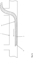
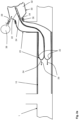
- a known first lining hose 10 made of overlapping wound fiber bands 2, as is known in particular from WO-A00/73692 known, is drawn into the channel to be rehabilitated or into the pipe 1 in the non-expanded state.
- the section of the pipe 1 to be rehabilitated is then closed at the ends by schematically indicated packers 4 and expanded by means of a compressed air source 8 so that the first lining hose 10 is applied to the inner wall of the pipe 1 to be rehabilitated.
- the fiber ribbons 2, which are wound in particular on an inner film tube 12 which is permeable to UV light and which is Figure 1c are impregnated with a reaction resin containing photoinitiators, which can be cured by the light of a radiation source 6, which for this purpose is pulled through the expanded first lining tube.
- first lining tube 10 which contains at least one, but preferably three, four or even more layers of cured fiber tapes 2 wound continuously one above the other, of which the outermost, radially outer layer can additionally be surrounded by an outer film tube 16 with a fleece layer 18 laminated on the inside, as shown in Figure 3
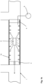
- a second lining tube 20 is then inserted, as shown in Figure 2a is indicated.
- the second lining tube 20 comprises a circumferentially closed inner film layer 22 onto which a fleece layer 24, for example a polyester fleece or a glass fleece with a thickness of, for example, 1 mm or more, is laminated, i.e. is applied using a known melting process, in particular by melting the plastic material from which the inner film layer 22 is formed.
- the inner film layer 22 of the second lining tube 20 is preferably a seamless or overlapping glued PE film and/or a seamless or overlapping glued PU film and/or a seamless or overlapping glued PA film or a composite film made of PE/PA.
- the inner film of the inner film layer preferably has a wall thickness of more than 1 mm, where PE designates the plastic polyethylene and PA the plastic polyamide.
- the fleece can also be a PE fleece and/or a PP fleece and/or a Pan fleece, where PP refers to the plastic polypropylene and Pan refers to the plastic polyacrylonitrile.
- the second lining tube 20 which in the same way as the inner film tube 12 of the first lining tube 10 can have a longitudinal seam at which the overlapping longitudinal edges of the inner film layers are connected to one another, for example by welding or gluing, is first filled with a further reaction resin, preferably epoxy resin, in order to impregnate the fleece layer 24 with the further reaction resin.
- a further reaction resin preferably epoxy resin
- the further resin can also be another liquid reaction resin, such as in particular a polyurethane resin (PU resin) containing UV initiators, epoxy resin (EP resin) is preferably used as such, without the invention being restricted to this.
- the second lining hose 20 with the inner film layer 22 arranged on the outside can be filled with an appropriate amount of additional liquid reaction resin, which consists of binder and hardener components in a known manner and is mixed on site, i.e., for example, on the construction site, immediately before the resin is filled into the interior of the second lining hose 20.
- additional liquid reaction resin which consists of binder and hardener components in a known manner and is mixed on site, i.e., for example, on the construction site, immediately before the resin is filled into the interior of the second lining hose 20.
- the second lining hose 20 is moved, for example, through a roller gap (not shown in detail) that is formed between a first calibration roller and a second calibration roller.
- the pulling in of the second lining tube 20 prepared in the manner described above can be carried out, for example, by means of a Figure 2a only schematically indicated inversion device 30.
- This can have a drum body 32, which has a nozzle-like outlet opening 34, through which a first end of the second lining hose 10 impregnated with epoxy resin is passed and, after the first end has been folded from the inside to the outside, on the outside of the nozzle-like Outlet opening 34 is sealed, for example by means of a clamp 36.
- the interior of the drum body 32 in which the second lining hose 20 is held, for example wound on a drum not shown in detail, is pressurized with compressed air, which is fed via a Figure 2a schematically indicated compressed air source 38.
- the interior of the second lining hose can be exposed to a hot gas to accelerate the hardening of the additional reaction resin, which can be provided, for example, by heating the compressed air from the compressed air source 38.
- a hot gas to accelerate the hardening of the additional reaction resin, which can be provided, for example, by heating the compressed air from the compressed air source 38.
- water can also be used instead of a compressed air source 38 to push the second lining hose 20 into the first lining hose 10.
- hot water or hot steam can also be used for hardening, which is circulated through the inserted second lining hose.
- the supply of heat significantly accelerates the hardening of the additional reaction resin and advantageously shortens the time required to renovate the pipe 1 to be renovated.
- the overlapping parts of the hardened fleece material of the fleece layer 24 are removed, for example with a milling robot, so that the water-carrying pipe 1 is completely sealed by the first lining hose 10 and the second lining hose 20 pulled into it.
- the inner film layer 24 has an overlap area in the area of a longitudinal seam or not, since the connection by the additional reaction resin and the fleece layer 24, particularly when using epoxy resin, reliably prevents the inner film layer 24 from coming off in this area. In the case of a water-carrying pipe, this results in the renovated pipe 1 being extremely resistant to flushing, which guarantees a very long service life.
- the curing of the first lining tube 10 can in principle also be carried out by using a reaction resin containing peroxides using hot steam or hot water
- the first lining tube, as described above, is preferably cured by UV light, which results in the advantage of a significantly shortened curing time and a considerably reduced equipment outlay compared to the use of peroxides and hot steam.
- a radiation source 6 which has a plurality of UV vapor lamps or UV light-emitting LEDs, which are preferably accommodated in several modules which are movably pulled through the line 1 in the form of a chain not shown in detail in the drawings.
- the further reaction resin is, as already mentioned, preferably a known self-curing epoxy resin or a polyurethane resin, which is provided by mixing two components and whose curing is accelerated by the supply of heat.
- a known self-curing epoxy resin or a polyurethane resin which is provided by mixing two components and whose curing is accelerated by the supply of heat.
- hot gas which is introduced into the interior of the second lining tube 20 by heating the compressed air provided by the compressed air source 38
- the interior of the second lining tube 20 is irradiated from the inside by an infrared radiation source, for example by an infrared lamp, which is similar to the one in Figure 1b shown radiation source 6 is pulled through the second lining tube 20.
- the further reaction resin can also be a liquid reaction resin that can be cured by UV light, in particular epoxy resin, which is cured, for example, by closing the ends of the second lining tube 20 with packers 4, pressurizing the interior of the second lining tube 20 with compressed air and the UV light source 6, as in Figure 1b shown, in the same way as with the first lining hose 10 through the interior of the second lining hose 20 in this case.
- This has the advantage that on the one hand the same packers and the same radiation source 6 can be used, and on the other hand the mixing of the further reaction resin immediately before the second lining hose 20 is inserted on the construction site can be omitted.
- the second lining hose 20 is already impregnated with the UV-curing additional reaction resin during production and transported to the construction site in a container that is impermeable to UV light.
- This measure results in the further advantage that not only the time at which the curing of the second lining tube 20 is to take place can be freely selected, but that by using the same UV light source and the comparatively thin-walled inner film layer 24 of the second lining tube 20, the additional reaction resin can be cured in the shortest possible time.
- both the first lining tube 10 and the second lining tube 20 contain a reaction resin that can be cured by UV light, preferably a UP resin in the case of the first lining tube 10 and a light-curable epoxy resin or PU resin in the case of the second lining tube 20, the two lining tubes 10, 20 can be cured in a highly flexible manner and in the shortest possible time using one and the same radiation source, and the respective curing process can be monitored by appropriate sensors, for example to ensure a high quality of the end product.
- the first lining hose 10 is an old hose arranged in a water-carrying pipe 1, which is permeable to water at least at one point and which is cleaned and dried on its inner peripheral surface before the second lining hose 20 is folded in, in order to ensure that the inner fleece layer 24 adheres well to the additional reactive resin.
- the permeable old hose is the wound first lining hose 10, in which the inner film hose 12 has a local perforation, so that when the first lining hose 10 is expanded using compressed air, the compressed air flows out through this perforated point and the laminate underneath, and the liquid reactive resin is blown out of the laminate. After hardening, a leak occurs at this point through which the water in the pipe 1 can escape.
- the method according to the invention opens up the possibility of the leak being completely sealed by the inward-folding of the second lining tube 20, and in addition the additional reaction resin in the fleece layer 24 penetrating the openings formed in the laminate of the first lining tube 10 in the area of the leak and closing them.
- This not only seals the leak, but also advantageously almost completely restores the mechanical strength of the laminate of the first lining tube 10 in this area after the additional reaction resin has hardened, so that the entire lining tube meets the required mechanical strength requirements even in the case of a pressure line.
- the method described above also applies accordingly to pressure lines for liquid or gaseous media that are to be renovated, such as oil and gas pipelines or lines in industrial plants, etc.
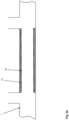
- Figure 3 shows a schematic partial representation of an arrangement 40 according to the invention formed in the manner described above, consisting of a hardened first lining tube 10 and an inserted hardened second lining tube 20 with the respective layers.
- the arrangement does not have an inner film tube 12, which is only required for pulling in, expanding and hardening the first lining tube 10 and according to the representation of Fig. 1c is removed before inserting the second lining tube 20.
Landscapes
- Engineering & Computer Science (AREA)
- General Engineering & Computer Science (AREA)
- Mechanical Engineering (AREA)
- Lining Or Joining Of Plastics Or The Like (AREA)
Priority Applications (1)
| Application Number | Priority Date | Filing Date | Title |
|---|---|---|---|
| PL18786720.5T PL3695157T5 (pl) | 2017-10-10 | 2018-10-10 | Sposób i układ do renowacji przewodu przewodzącego medium ciekłe lub gazowe |
Applications Claiming Priority (3)
| Application Number | Priority Date | Filing Date | Title |
|---|---|---|---|
| DE102017009436 | 2017-10-10 | ||
| DE102018001598.0A DE102018001598A1 (de) | 2017-10-10 | 2018-03-01 | Verfahren und Anordnung zur Sanierung einer ein flüssiges oder gasförmiges Medium führenden Leitung |
| PCT/EP2018/077569 WO2019072900A1 (de) | 2017-10-10 | 2018-10-10 | Verfahren und anordnung zur sanierung einer ein flüssiges oder gasförmiges medium führenden leitung |
Publications (3)
| Publication Number | Publication Date |
|---|---|
| EP3695157A1 EP3695157A1 (de) | 2020-08-19 |
| EP3695157B1 EP3695157B1 (de) | 2021-09-08 |
| EP3695157B2 true EP3695157B2 (de) | 2024-08-14 |
Family
ID=65817230
Family Applications (1)
| Application Number | Title | Priority Date | Filing Date |
|---|---|---|---|
| EP18786720.5A Active EP3695157B2 (de) | 2017-10-10 | 2018-10-10 | Verfahren und anordnung zur sanierung einer ein flüssiges oder gasförmiges medium führenden leitung |
Country Status (5)
| Country | Link |
|---|---|
| EP (1) | EP3695157B2 (pl) |
| DE (1) | DE102018001598A1 (pl) |
| ES (1) | ES2901900T5 (pl) |
| PL (1) | PL3695157T5 (pl) |
| WO (1) | WO2019072900A1 (pl) |
Families Citing this family (2)
| Publication number | Priority date | Publication date | Assignee | Title |
|---|---|---|---|---|
| US11674628B2 (en) | 2017-08-18 | 2023-06-13 | Moray Group, Llc | Method, apparatus and system for lining conduits |
| CN116576332B (zh) * | 2023-07-12 | 2023-09-01 | 山东方大新材料科技有限公司 | 一种管道修复装置 |
Citations (4)
| Publication number | Priority date | Publication date | Assignee | Title |
|---|---|---|---|---|
| EP0393304A2 (de) † | 1989-02-27 | 1990-10-24 | Hans Müller | Verfahren zum Auskleiden eines im Erdreich verlegten Leitungsrohres |
| WO2000025057A1 (de) † | 1998-10-26 | 2000-05-04 | Siegfried Schwert | Schlauch zur auskleidung von rohrleitungen und verfahren zu dessen herstellung |
| EP2768655B1 (de) † | 2012-10-18 | 2015-08-05 | Siegfried Schwert | Auskleidungsschlauch, rehabilitiertes druckrohr und verfahren zum rehabilitieren eines druckrohrs |
| US20170082220A1 (en) † | 2015-09-22 | 2017-03-23 | Ina Acquisition Corp. | Method of lining pipe with high strength liner, high strength liner, and pipe lined with high strength liner |
Family Cites Families (4)
| Publication number | Priority date | Publication date | Assignee | Title |
|---|---|---|---|---|
| DE19924251A1 (de) | 1999-05-27 | 2000-11-30 | Joachim Brandenburger | Auskleidungsschlauch mit auf Folienschlauch aufkaschierter Vliesschicht |
| US7766048B2 (en) | 2004-11-03 | 2010-08-03 | Ina Acquisition Corp. | Installation of cured in place liners with air and flow-through steam to cure |
| EP2573442B1 (de) | 2011-09-23 | 2015-12-30 | Saertex multicom GmbH | Innenbeschichteter Liner |
| DE102012015047A1 (de) | 2012-07-31 | 2014-05-28 | Brandenburger Patentverwertung GbR (vertretungsberechtigter Gesellschafter Joachim Brandenburger, 82467 Garmisch-Partenkirchen) | Auskleidungsschlauch mit einem innenfolienschlauch zur Auskleidung von Rohrleitungen und Verfaren zur fortlaufenden Herstellung eines solchen |
-
2018
- 2018-03-01 DE DE102018001598.0A patent/DE102018001598A1/de active Pending
- 2018-10-10 WO PCT/EP2018/077569 patent/WO2019072900A1/de not_active Ceased
- 2018-10-10 EP EP18786720.5A patent/EP3695157B2/de active Active
- 2018-10-10 ES ES18786720T patent/ES2901900T5/es active Active
- 2018-10-10 PL PL18786720.5T patent/PL3695157T5/pl unknown
Patent Citations (4)
| Publication number | Priority date | Publication date | Assignee | Title |
|---|---|---|---|---|
| EP0393304A2 (de) † | 1989-02-27 | 1990-10-24 | Hans Müller | Verfahren zum Auskleiden eines im Erdreich verlegten Leitungsrohres |
| WO2000025057A1 (de) † | 1998-10-26 | 2000-05-04 | Siegfried Schwert | Schlauch zur auskleidung von rohrleitungen und verfahren zu dessen herstellung |
| EP2768655B1 (de) † | 2012-10-18 | 2015-08-05 | Siegfried Schwert | Auskleidungsschlauch, rehabilitiertes druckrohr und verfahren zum rehabilitieren eines druckrohrs |
| US20170082220A1 (en) † | 2015-09-22 | 2017-03-23 | Ina Acquisition Corp. | Method of lining pipe with high strength liner, high strength liner, and pipe lined with high strength liner |
Non-Patent Citations (8)
| Title |
|---|
| Auftrag vom 01. 10.2014 † |
| Bauzeitenplan vom 06.10.2014 † |
| Leitungsplan vom Ort der Arbeiten † |
| Rechnung vom 04.11.2014 † |
| Rechnung vom 07.10.2014 † |
| Rechnung vom 10.10 2014 † |
| Sanierungsprotokoll vom 16. 10. 2014 mit ergänzender Eintragung vom 21.10.2014 † |
| Visitenkarte des involvierten Vertreters des Bauherrn Werksbescheinigung † |
Also Published As
| Publication number | Publication date |
|---|---|
| EP3695157A1 (de) | 2020-08-19 |
| EP3695157B1 (de) | 2021-09-08 |
| DE102018001598A1 (de) | 2019-04-11 |
| WO2019072900A1 (de) | 2019-04-18 |
| PL3695157T3 (pl) | 2022-02-14 |
| PL3695157T5 (pl) | 2024-11-25 |
| ES2901900T3 (es) | 2022-03-24 |
| ES2901900T5 (en) | 2025-01-28 |
Similar Documents
| Publication | Publication Date | Title |
|---|---|---|
| EP2768655B1 (de) | Auskleidungsschlauch, rehabilitiertes druckrohr und verfahren zum rehabilitieren eines druckrohrs | |
| DE69019516T2 (de) | Relining von pipelines und kanälen. | |
| EP3359858B1 (de) | Auskleidungsschlauch für die kanalsanierung sowie verfahren zur herstellung eines solchen | |
| EP0228998A1 (de) | Verfahren zur Sanierung verlegter Rohrleitungen | |
| DE3106012A1 (de) | Verfahren und vorrichtung zum auskleiden der innenflaeche einer rohrleitung | |
| DE102013203840A1 (de) | Kurzliner zur Kanalsanierung | |
| EP3695157B2 (de) | Verfahren und anordnung zur sanierung einer ein flüssiges oder gasförmiges medium führenden leitung | |
| DE102015117372A1 (de) | Vorrichtung zum Aushärten eines Auskleidungsschlauchs | |
| EP4264109B1 (de) | Auskleidungsschlauch zur sanierung von defekten kanalrohren und verfahren zur herstellung sowie installation eines solchen | |
| EP4264108B1 (de) | Auskleidungsschlauch zur sanierung von defekten kanalschächten und verfahren zur herstellung sowie installation eines solchen | |
| DE3520696A1 (de) | Verfahren zum sanieren einer im erdreich verlegten rohrleitung | |
| EP1798462A1 (de) | Verfahren zum Sanieren von Abzweigleitungen von Kanalrohren | |
| DE202014104357U1 (de) | Set zum Sanieren eines Kanals | |
| EP3980679B1 (de) | Anordnung und verfahren zum sanieren eines rohres, insbesondere eines abwasserrohres | |
| EP3210771B1 (de) | Auskleidungsschlauch für die kanalisierung sowie verfahren zur herstellung eines solchen | |
| DE102006038607B3 (de) | Verfahren zur grabenlosen Reparatur von Schadstellen in Kanälen und Rohrleitungen | |
| EP3614032B1 (de) | Vorrichtung und verfahren zur sanierung eines rohrabschnitts eines rohrleitungssystems | |
| EP2913175B1 (de) | Verfahren zum Auskleiden einer Rohrleitung | |
| DE202020005929U1 (de) | Auskleidungsschlauch zur Sanierung von defekten Kanalschächten | |
| DE102020104525A1 (de) | Vorabdichtung vor dem sanieren einer leitung | |
| DE202011109427U1 (de) | Vorrrichtung zur Sanierung von Kanalrohren mit einem Sanierungspacker | |
| EP2558765A1 (de) | Relining-schlauch und verfahren zum sanieren eines schlitzrinnenkanals |
Legal Events
| Date | Code | Title | Description |
|---|---|---|---|
| STAA | Information on the status of an ep patent application or granted ep patent |
Free format text: STATUS: UNKNOWN |
|
| STAA | Information on the status of an ep patent application or granted ep patent |
Free format text: STATUS: THE INTERNATIONAL PUBLICATION HAS BEEN MADE |
|
| PUAI | Public reference made under article 153(3) epc to a published international application that has entered the european phase |
Free format text: ORIGINAL CODE: 0009012 |
|
| STAA | Information on the status of an ep patent application or granted ep patent |
Free format text: STATUS: REQUEST FOR EXAMINATION WAS MADE |
|
| 17P | Request for examination filed |
Effective date: 20200511 |
|
| AK | Designated contracting states |
Kind code of ref document: A1 Designated state(s): AL AT BE BG CH CY CZ DE DK EE ES FI FR GB GR HR HU IE IS IT LI LT LU LV MC MK MT NL NO PL PT RO RS SE SI SK SM TR |
|
| AX | Request for extension of the european patent |
Extension state: BA ME |
|
| DAV | Request for validation of the european patent (deleted) | ||
| DAX | Request for extension of the european patent (deleted) | ||
| GRAP | Despatch of communication of intention to grant a patent |
Free format text: ORIGINAL CODE: EPIDOSNIGR1 |
|
| STAA | Information on the status of an ep patent application or granted ep patent |
Free format text: STATUS: GRANT OF PATENT IS INTENDED |
|
| GRAJ | Information related to disapproval of communication of intention to grant by the applicant or resumption of examination proceedings by the epo deleted |
Free format text: ORIGINAL CODE: EPIDOSDIGR1 |
|
| STAA | Information on the status of an ep patent application or granted ep patent |
Free format text: STATUS: REQUEST FOR EXAMINATION WAS MADE |
|
| INTG | Intention to grant announced |
Effective date: 20210511 |
|
| INTC | Intention to grant announced (deleted) | ||
| GRAP | Despatch of communication of intention to grant a patent |
Free format text: ORIGINAL CODE: EPIDOSNIGR1 |
|
| STAA | Information on the status of an ep patent application or granted ep patent |
Free format text: STATUS: GRANT OF PATENT IS INTENDED |
|
| INTG | Intention to grant announced |
Effective date: 20210625 |
|
| GRAS | Grant fee paid |
Free format text: ORIGINAL CODE: EPIDOSNIGR3 |
|
| GRAA | (expected) grant |
Free format text: ORIGINAL CODE: 0009210 |
|
| STAA | Information on the status of an ep patent application or granted ep patent |
Free format text: STATUS: THE PATENT HAS BEEN GRANTED |
|
| AK | Designated contracting states |
Kind code of ref document: B1 Designated state(s): AL AT BE BG CH CY CZ DE DK EE ES FI FR GB GR HR HU IE IS IT LI LT LU LV MC MK MT NL NO PL PT RO RS SE SI SK SM TR |
|
| REG | Reference to a national code |
Ref country code: GB Ref legal event code: FG4D Free format text: NOT ENGLISH |
|
| REG | Reference to a national code |
Ref country code: AT Ref legal event code: REF Ref document number: 1428887 Country of ref document: AT Kind code of ref document: T Effective date: 20210915 Ref country code: CH Ref legal event code: EP |
|
| REG | Reference to a national code |
Ref country code: IE Ref legal event code: FG4D Free format text: LANGUAGE OF EP DOCUMENT: GERMAN |
|
| REG | Reference to a national code |
Ref country code: DE Ref legal event code: R096 Ref document number: 502018007030 Country of ref document: DE |
|
| REG | Reference to a national code |
Ref country code: NO Ref legal event code: T2 Effective date: 20210908 |
|
| REG | Reference to a national code |
Ref country code: LT Ref legal event code: MG9D |
|
| REG | Reference to a national code |
Ref country code: NL Ref legal event code: FP |
|
| PG25 | Lapsed in a contracting state [announced via postgrant information from national office to epo] |
Ref country code: FI Free format text: LAPSE BECAUSE OF FAILURE TO SUBMIT A TRANSLATION OF THE DESCRIPTION OR TO PAY THE FEE WITHIN THE PRESCRIBED TIME-LIMIT Effective date: 20210908 Ref country code: HR Free format text: LAPSE BECAUSE OF FAILURE TO SUBMIT A TRANSLATION OF THE DESCRIPTION OR TO PAY THE FEE WITHIN THE PRESCRIBED TIME-LIMIT Effective date: 20210908 Ref country code: SE Free format text: LAPSE BECAUSE OF FAILURE TO SUBMIT A TRANSLATION OF THE DESCRIPTION OR TO PAY THE FEE WITHIN THE PRESCRIBED TIME-LIMIT Effective date: 20210908 Ref country code: RS Free format text: LAPSE BECAUSE OF FAILURE TO SUBMIT A TRANSLATION OF THE DESCRIPTION OR TO PAY THE FEE WITHIN THE PRESCRIBED TIME-LIMIT Effective date: 20210908 Ref country code: LT Free format text: LAPSE BECAUSE OF FAILURE TO SUBMIT A TRANSLATION OF THE DESCRIPTION OR TO PAY THE FEE WITHIN THE PRESCRIBED TIME-LIMIT Effective date: 20210908 |
|
| PG25 | Lapsed in a contracting state [announced via postgrant information from national office to epo] |
Ref country code: LV Free format text: LAPSE BECAUSE OF FAILURE TO SUBMIT A TRANSLATION OF THE DESCRIPTION OR TO PAY THE FEE WITHIN THE PRESCRIBED TIME-LIMIT Effective date: 20210908 Ref country code: GR Free format text: LAPSE BECAUSE OF FAILURE TO SUBMIT A TRANSLATION OF THE DESCRIPTION OR TO PAY THE FEE WITHIN THE PRESCRIBED TIME-LIMIT Effective date: 20211209 |
|
| REG | Reference to a national code |
Ref country code: ES Ref legal event code: FG2A Ref document number: 2901900 Country of ref document: ES Kind code of ref document: T3 Effective date: 20220324 |
|
| PG25 | Lapsed in a contracting state [announced via postgrant information from national office to epo] |
Ref country code: IS Free format text: LAPSE BECAUSE OF FAILURE TO SUBMIT A TRANSLATION OF THE DESCRIPTION OR TO PAY THE FEE WITHIN THE PRESCRIBED TIME-LIMIT Effective date: 20220108 Ref country code: SM Free format text: LAPSE BECAUSE OF FAILURE TO SUBMIT A TRANSLATION OF THE DESCRIPTION OR TO PAY THE FEE WITHIN THE PRESCRIBED TIME-LIMIT Effective date: 20210908 Ref country code: SK Free format text: LAPSE BECAUSE OF FAILURE TO SUBMIT A TRANSLATION OF THE DESCRIPTION OR TO PAY THE FEE WITHIN THE PRESCRIBED TIME-LIMIT Effective date: 20210908 Ref country code: PT Free format text: LAPSE BECAUSE OF FAILURE TO SUBMIT A TRANSLATION OF THE DESCRIPTION OR TO PAY THE FEE WITHIN THE PRESCRIBED TIME-LIMIT Effective date: 20220110 Ref country code: EE Free format text: LAPSE BECAUSE OF FAILURE TO SUBMIT A TRANSLATION OF THE DESCRIPTION OR TO PAY THE FEE WITHIN THE PRESCRIBED TIME-LIMIT Effective date: 20210908 Ref country code: CZ Free format text: LAPSE BECAUSE OF FAILURE TO SUBMIT A TRANSLATION OF THE DESCRIPTION OR TO PAY THE FEE WITHIN THE PRESCRIBED TIME-LIMIT Effective date: 20210908 Ref country code: AL Free format text: LAPSE BECAUSE OF FAILURE TO SUBMIT A TRANSLATION OF THE DESCRIPTION OR TO PAY THE FEE WITHIN THE PRESCRIBED TIME-LIMIT Effective date: 20210908 |
|
| REG | Reference to a national code |
Ref country code: DE Ref legal event code: R026 Ref document number: 502018007030 Country of ref document: DE |
|
| PLBI | Opposition filed |
Free format text: ORIGINAL CODE: 0009260 |
|
| PLAX | Notice of opposition and request to file observation + time limit sent |
Free format text: ORIGINAL CODE: EPIDOSNOBS2 |
|
| PG25 | Lapsed in a contracting state [announced via postgrant information from national office to epo] |
Ref country code: MC Free format text: LAPSE BECAUSE OF FAILURE TO SUBMIT A TRANSLATION OF THE DESCRIPTION OR TO PAY THE FEE WITHIN THE PRESCRIBED TIME-LIMIT Effective date: 20210908 |
|
| 26 | Opposition filed |
Opponent name: KARL WEISS TECHNOLOGIES GMBH Effective date: 20220608 |
|
| PG25 | Lapsed in a contracting state [announced via postgrant information from national office to epo] |
Ref country code: DK Free format text: LAPSE BECAUSE OF FAILURE TO SUBMIT A TRANSLATION OF THE DESCRIPTION OR TO PAY THE FEE WITHIN THE PRESCRIBED TIME-LIMIT Effective date: 20210908 |
|
| PG25 | Lapsed in a contracting state [announced via postgrant information from national office to epo] |
Ref country code: SI Free format text: LAPSE BECAUSE OF FAILURE TO SUBMIT A TRANSLATION OF THE DESCRIPTION OR TO PAY THE FEE WITHIN THE PRESCRIBED TIME-LIMIT Effective date: 20210908 |
|
| PLAF | Information modified related to communication of a notice of opposition and request to file observations + time limit |
Free format text: ORIGINAL CODE: EPIDOSCOBS2 |
|
| PLBB | Reply of patent proprietor to notice(s) of opposition received |
Free format text: ORIGINAL CODE: EPIDOSNOBS3 |
|
| PGFP | Annual fee paid to national office [announced via postgrant information from national office to epo] |
Ref country code: IE Payment date: 20221021 Year of fee payment: 5 |
|
| PG25 | Lapsed in a contracting state [announced via postgrant information from national office to epo] |
Ref country code: CY Free format text: LAPSE BECAUSE OF FAILURE TO SUBMIT A TRANSLATION OF THE DESCRIPTION OR TO PAY THE FEE WITHIN THE PRESCRIBED TIME-LIMIT Effective date: 20210908 |
|
| PG25 | Lapsed in a contracting state [announced via postgrant information from national office to epo] |
Ref country code: HU Free format text: LAPSE BECAUSE OF FAILURE TO SUBMIT A TRANSLATION OF THE DESCRIPTION OR TO PAY THE FEE WITHIN THE PRESCRIBED TIME-LIMIT; INVALID AB INITIO Effective date: 20181010 |
|
| PG25 | Lapsed in a contracting state [announced via postgrant information from national office to epo] |
Ref country code: MK Free format text: LAPSE BECAUSE OF FAILURE TO SUBMIT A TRANSLATION OF THE DESCRIPTION OR TO PAY THE FEE WITHIN THE PRESCRIBED TIME-LIMIT Effective date: 20210908 |
|
| PUAH | Patent maintained in amended form |
Free format text: ORIGINAL CODE: 0009272 |
|
| STAA | Information on the status of an ep patent application or granted ep patent |
Free format text: STATUS: PATENT MAINTAINED AS AMENDED |
|
| 27A | Patent maintained in amended form |
Effective date: 20240814 |
|
| AK | Designated contracting states |
Kind code of ref document: B2 Designated state(s): AL AT BE BG CH CY CZ DE DK EE ES FI FR GB GR HR HU IE IS IT LI LT LU LV MC MK MT NL NO PL PT RO RS SE SI SK SM TR |
|
| REG | Reference to a national code |
Ref country code: DE Ref legal event code: R102 Ref document number: 502018007030 Country of ref document: DE |
|
| REG | Reference to a national code |
Ref country code: NL Ref legal event code: FP |
|
| PG25 | Lapsed in a contracting state [announced via postgrant information from national office to epo] |
Ref country code: MT Free format text: LAPSE BECAUSE OF FAILURE TO SUBMIT A TRANSLATION OF THE DESCRIPTION OR TO PAY THE FEE WITHIN THE PRESCRIBED TIME-LIMIT Effective date: 20210908 |
|
| PG25 | Lapsed in a contracting state [announced via postgrant information from national office to epo] |
Ref country code: IE Free format text: LAPSE BECAUSE OF NON-PAYMENT OF DUE FEES Effective date: 20231010 |
|
| PG25 | Lapsed in a contracting state [announced via postgrant information from national office to epo] |
Ref country code: IE Free format text: LAPSE BECAUSE OF NON-PAYMENT OF DUE FEES Effective date: 20231010 |
|
| REG | Reference to a national code |
Ref country code: ES Ref legal event code: DC2A Ref document number: 2901900 Country of ref document: ES Kind code of ref document: T5 Effective date: 20250128 |
|
| PGFP | Annual fee paid to national office [announced via postgrant information from national office to epo] |
Ref country code: PL Payment date: 20250930 Year of fee payment: 8 |
|
| REG | Reference to a national code |
Ref country code: CH Ref legal event code: U11 Free format text: ST27 STATUS EVENT CODE: U-0-0-U10-U11 (AS PROVIDED BY THE NATIONAL OFFICE) Effective date: 20251101 |
|
| PGFP | Annual fee paid to national office [announced via postgrant information from national office to epo] |
Ref country code: NL Payment date: 20251023 Year of fee payment: 8 Ref country code: LU Payment date: 20251022 Year of fee payment: 8 |
|
| REG | Reference to a national code |
Ref country code: DE Ref legal event code: R082 Ref document number: 502018007030 Country of ref document: DE Representative=s name: KESSELHUT, WOLF, DIPL.-PHYS., DE |
|
| PGFP | Annual fee paid to national office [announced via postgrant information from national office to epo] |
Ref country code: DE Payment date: 20251020 Year of fee payment: 8 |
|
| PGFP | Annual fee paid to national office [announced via postgrant information from national office to epo] |
Ref country code: GB Payment date: 20251024 Year of fee payment: 8 |
|
| PGFP | Annual fee paid to national office [announced via postgrant information from national office to epo] |
Ref country code: NO Payment date: 20251022 Year of fee payment: 8 |
|
| PGFP | Annual fee paid to national office [announced via postgrant information from national office to epo] |
Ref country code: AT Payment date: 20251021 Year of fee payment: 8 |
|
| PGFP | Annual fee paid to national office [announced via postgrant information from national office to epo] |
Ref country code: IT Payment date: 20251031 Year of fee payment: 8 |
|
| PGFP | Annual fee paid to national office [announced via postgrant information from national office to epo] |
Ref country code: FR Payment date: 20251027 Year of fee payment: 8 |
|
| PGFP | Annual fee paid to national office [announced via postgrant information from national office to epo] |
Ref country code: BE Payment date: 20251022 Year of fee payment: 8 Ref country code: TR Payment date: 20251002 Year of fee payment: 8 |
|
| PGFP | Annual fee paid to national office [announced via postgrant information from national office to epo] |
Ref country code: CH Payment date: 20251101 Year of fee payment: 8 |
|
| PGFP | Annual fee paid to national office [announced via postgrant information from national office to epo] |
Ref country code: BG Payment date: 20251023 Year of fee payment: 8 |
|
| PGFP | Annual fee paid to national office [announced via postgrant information from national office to epo] |
Ref country code: RO Payment date: 20251006 Year of fee payment: 8 |
|
| PGFP | Annual fee paid to national office [announced via postgrant information from national office to epo] |
Ref country code: ES Payment date: 20251114 Year of fee payment: 8 |