EP3694717B1 - Sheet-processing machine comprising a sheet transport device, and method for transporting sheets from a sheet-guiding cylinder to a sheet conveyor system - Google Patents
Sheet-processing machine comprising a sheet transport device, and method for transporting sheets from a sheet-guiding cylinder to a sheet conveyor system Download PDFInfo
- Publication number
- EP3694717B1 EP3694717B1 EP18782711.8A EP18782711A EP3694717B1 EP 3694717 B1 EP3694717 B1 EP 3694717B1 EP 18782711 A EP18782711 A EP 18782711A EP 3694717 B1 EP3694717 B1 EP 3694717B1
- Authority
- EP
- European Patent Office
- Prior art keywords
- sheet
- fixing device
- processing machine
- hub
- assigned
- Prior art date
- Legal status (The legal status is an assumption and is not a legal conclusion. Google has not performed a legal analysis and makes no representation as to the accuracy of the status listed.)
- Active
Links
- 238000012545 processing Methods 0.000 title claims description 32
- 238000000034 method Methods 0.000 title claims description 13
- 238000006073 displacement reaction Methods 0.000 claims description 9
- 230000002093 peripheral effect Effects 0.000 claims 1
- 238000007639 printing Methods 0.000 description 39
- 230000000694 effects Effects 0.000 description 12
- 238000003825 pressing Methods 0.000 description 9
- 238000012546 transfer Methods 0.000 description 9
- 239000000463 material Substances 0.000 description 8
- 238000011144 upstream manufacturing Methods 0.000 description 6
- 230000008569 process Effects 0.000 description 5
- 238000012423 maintenance Methods 0.000 description 4
- 230000009471 action Effects 0.000 description 3
- 230000008859 change Effects 0.000 description 3
- 239000011248 coating agent Substances 0.000 description 3
- 238000000576 coating method Methods 0.000 description 3
- 241000252169 Catostomus commersonii Species 0.000 description 2
- 238000004140 cleaning Methods 0.000 description 2
- 238000010276 construction Methods 0.000 description 2
- 230000001276 controlling effect Effects 0.000 description 2
- 239000013013 elastic material Substances 0.000 description 2
- 239000000203 mixture Substances 0.000 description 2
- 230000001105 regulatory effect Effects 0.000 description 2
- 241000252254 Catostomidae Species 0.000 description 1
- 241000196324 Embryophyta Species 0.000 description 1
- 241000124008 Mammalia Species 0.000 description 1
- 230000004913 activation Effects 0.000 description 1
- 230000008901 benefit Effects 0.000 description 1
- 238000002508 contact lithography Methods 0.000 description 1
- 238000011109 contamination Methods 0.000 description 1
- 238000000151 deposition Methods 0.000 description 1
- 238000013461 design Methods 0.000 description 1
- 238000009792 diffusion process Methods 0.000 description 1
- 238000010410 dusting Methods 0.000 description 1
- 230000008030 elimination Effects 0.000 description 1
- 238000003379 elimination reaction Methods 0.000 description 1
- 238000005265 energy consumption Methods 0.000 description 1
- 239000011888 foil Substances 0.000 description 1
- 238000007689 inspection Methods 0.000 description 1
- 239000003973 paint Substances 0.000 description 1
- 239000000843 powder Substances 0.000 description 1
- 238000003908 quality control method Methods 0.000 description 1
- 230000000284 resting effect Effects 0.000 description 1
- 230000000717 retained effect Effects 0.000 description 1
- 238000005096 rolling process Methods 0.000 description 1
- 238000007650 screen-printing Methods 0.000 description 1
- 230000008054 signal transmission Effects 0.000 description 1
- 230000001360 synchronised effect Effects 0.000 description 1
- 238000005406 washing Methods 0.000 description 1
Images

Classifications
-
- B—PERFORMING OPERATIONS; TRANSPORTING
- B41—PRINTING; LINING MACHINES; TYPEWRITERS; STAMPS
- B41F—PRINTING MACHINES OR PRESSES
- B41F21/00—Devices for conveying sheets through printing apparatus or machines
- B41F21/08—Combinations of endless conveyors and grippers
-
- B—PERFORMING OPERATIONS; TRANSPORTING
- B65—CONVEYING; PACKING; STORING; HANDLING THIN OR FILAMENTARY MATERIAL
- B65H—HANDLING THIN OR FILAMENTARY MATERIAL, e.g. SHEETS, WEBS, CABLES
- B65H29/00—Delivering or advancing articles from machines; Advancing articles to or into piles
- B65H29/02—Delivering or advancing articles from machines; Advancing articles to or into piles by mechanical grippers engaging the leading edge only of the articles
- B65H29/04—Delivering or advancing articles from machines; Advancing articles to or into piles by mechanical grippers engaging the leading edge only of the articles the grippers being carried by endless chains or bands
- B65H29/041—Delivering or advancing articles from machines; Advancing articles to or into piles by mechanical grippers engaging the leading edge only of the articles the grippers being carried by endless chains or bands and introducing into a pile
-
- B—PERFORMING OPERATIONS; TRANSPORTING
- B65—CONVEYING; PACKING; STORING; HANDLING THIN OR FILAMENTARY MATERIAL
- B65H—HANDLING THIN OR FILAMENTARY MATERIAL, e.g. SHEETS, WEBS, CABLES
- B65H5/00—Feeding articles separated from piles; Feeding articles to machines
- B65H5/08—Feeding articles separated from piles; Feeding articles to machines by grippers, e.g. suction grippers
- B65H5/12—Revolving grippers, e.g. mounted on arms, frames or cylinders
-
- B—PERFORMING OPERATIONS; TRANSPORTING
- B65—CONVEYING; PACKING; STORING; HANDLING THIN OR FILAMENTARY MATERIAL
- B65H—HANDLING THIN OR FILAMENTARY MATERIAL, e.g. SHEETS, WEBS, CABLES
- B65H2301/00—Handling processes for sheets or webs
- B65H2301/40—Type of handling process
- B65H2301/44—Moving, forwarding, guiding material
- B65H2301/443—Moving, forwarding, guiding material by acting on surface of handled material
- B65H2301/4433—Moving, forwarding, guiding material by acting on surface of handled material by means holding the material
- B65H2301/44331—Moving, forwarding, guiding material by acting on surface of handled material by means holding the material at particular portion of handled material
-
- B—PERFORMING OPERATIONS; TRANSPORTING
- B65—CONVEYING; PACKING; STORING; HANDLING THIN OR FILAMENTARY MATERIAL
- B65H—HANDLING THIN OR FILAMENTARY MATERIAL, e.g. SHEETS, WEBS, CABLES
- B65H2301/00—Handling processes for sheets or webs
- B65H2301/40—Type of handling process
- B65H2301/44—Moving, forwarding, guiding material
- B65H2301/443—Moving, forwarding, guiding material by acting on surface of handled material
- B65H2301/4433—Moving, forwarding, guiding material by acting on surface of handled material by means holding the material
- B65H2301/44336—Moving, forwarding, guiding material by acting on surface of handled material by means holding the material using suction forces
-
- B—PERFORMING OPERATIONS; TRANSPORTING
- B65—CONVEYING; PACKING; STORING; HANDLING THIN OR FILAMENTARY MATERIAL
- B65H—HANDLING THIN OR FILAMENTARY MATERIAL, e.g. SHEETS, WEBS, CABLES
- B65H2301/00—Handling processes for sheets or webs
- B65H2301/40—Type of handling process
- B65H2301/44—Moving, forwarding, guiding material
- B65H2301/447—Moving, forwarding, guiding material transferring material between transport devices
- B65H2301/4471—Grippers, e.g. moved in paths enclosing an area
- B65H2301/44712—Grippers, e.g. moved in paths enclosing an area carried by chains or bands
-
- B—PERFORMING OPERATIONS; TRANSPORTING
- B65—CONVEYING; PACKING; STORING; HANDLING THIN OR FILAMENTARY MATERIAL
- B65H—HANDLING THIN OR FILAMENTARY MATERIAL, e.g. SHEETS, WEBS, CABLES
- B65H2301/00—Handling processes for sheets or webs
- B65H2301/40—Type of handling process
- B65H2301/44—Moving, forwarding, guiding material
- B65H2301/447—Moving, forwarding, guiding material transferring material between transport devices
- B65H2301/4471—Grippers, e.g. moved in paths enclosing an area
- B65H2301/44714—Grippers, e.g. moved in paths enclosing an area carried by rotating members
-
- B—PERFORMING OPERATIONS; TRANSPORTING
- B65—CONVEYING; PACKING; STORING; HANDLING THIN OR FILAMENTARY MATERIAL
- B65H—HANDLING THIN OR FILAMENTARY MATERIAL, e.g. SHEETS, WEBS, CABLES
- B65H2404/00—Parts for transporting or guiding the handled material
- B65H2404/30—Chains
- B65H2404/34—Gripper bars bridging at least two chains running synchronously and parallely
- B65H2404/341—Details of driving or return drum
-
- B—PERFORMING OPERATIONS; TRANSPORTING
- B65—CONVEYING; PACKING; STORING; HANDLING THIN OR FILAMENTARY MATERIAL
- B65H—HANDLING THIN OR FILAMENTARY MATERIAL, e.g. SHEETS, WEBS, CABLES
- B65H2404/00—Parts for transporting or guiding the handled material
- B65H2404/60—Other elements in face contact with handled material
- B65H2404/69—Other means designated for special purpose
- B65H2404/694—Non driven means for pressing the handled material on forwarding or guiding elements
-
- B—PERFORMING OPERATIONS; TRANSPORTING
- B65—CONVEYING; PACKING; STORING; HANDLING THIN OR FILAMENTARY MATERIAL
- B65H—HANDLING THIN OR FILAMENTARY MATERIAL, e.g. SHEETS, WEBS, CABLES
- B65H2406/00—Means using fluid
- B65H2406/30—Suction means
- B65H2406/34—Suction grippers
- B65H2406/345—Rotary suction grippers
-
- B—PERFORMING OPERATIONS; TRANSPORTING
- B65—CONVEYING; PACKING; STORING; HANDLING THIN OR FILAMENTARY MATERIAL
- B65H—HANDLING THIN OR FILAMENTARY MATERIAL, e.g. SHEETS, WEBS, CABLES
- B65H2511/00—Dimensions; Position; Numbers; Identification; Occurrences
- B65H2511/10—Size; Dimensions
-
- B—PERFORMING OPERATIONS; TRANSPORTING
- B65—CONVEYING; PACKING; STORING; HANDLING THIN OR FILAMENTARY MATERIAL
- B65H—HANDLING THIN OR FILAMENTARY MATERIAL, e.g. SHEETS, WEBS, CABLES
- B65H2511/00—Dimensions; Position; Numbers; Identification; Occurrences
- B65H2511/20—Location in space
-
- B—PERFORMING OPERATIONS; TRANSPORTING
- B65—CONVEYING; PACKING; STORING; HANDLING THIN OR FILAMENTARY MATERIAL
- B65H—HANDLING THIN OR FILAMENTARY MATERIAL, e.g. SHEETS, WEBS, CABLES
- B65H2701/00—Handled material; Storage means
- B65H2701/10—Handled articles or webs
- B65H2701/13—Parts concerned of the handled material
- B65H2701/131—Edges
- B65H2701/1313—Edges trailing edge
-
- B—PERFORMING OPERATIONS; TRANSPORTING
- B65—CONVEYING; PACKING; STORING; HANDLING THIN OR FILAMENTARY MATERIAL
- B65H—HANDLING THIN OR FILAMENTARY MATERIAL, e.g. SHEETS, WEBS, CABLES
- B65H2701/00—Handled material; Storage means
- B65H2701/10—Handled articles or webs
- B65H2701/13—Parts concerned of the handled material
- B65H2701/131—Edges
- B65H2701/1315—Edges side edges, i.e. regarded in context of transport
-
- B—PERFORMING OPERATIONS; TRANSPORTING
- B65—CONVEYING; PACKING; STORING; HANDLING THIN OR FILAMENTARY MATERIAL
- B65H—HANDLING THIN OR FILAMENTARY MATERIAL, e.g. SHEETS, WEBS, CABLES
- B65H2801/00—Application field
- B65H2801/03—Image reproduction devices
- B65H2801/21—Industrial-size printers, e.g. rotary printing press
-
- B—PERFORMING OPERATIONS; TRANSPORTING
- B65—CONVEYING; PACKING; STORING; HANDLING THIN OR FILAMENTARY MATERIAL
- B65H—HANDLING THIN OR FILAMENTARY MATERIAL, e.g. SHEETS, WEBS, CABLES
- B65H2801/00—Application field
- B65H2801/24—Post -processing devices
- B65H2801/31—Devices located downstream of industrial printers
Definitions
- the invention relates to a sheet processing machine with a sheet transport device with a sheet conveying system taking over a sheet from a sheet guiding cylinder and a method for conveying sheets from a sheet guiding cylinder to a sheet conveying system in a sheet processing machine.
- the trailing edge of the sheet is held by a cross member that extends over the maximum format width and has suction cups.
- the disadvantage is that the traverse to take over the sheet trailing edge is large and therefore dynamically unfavorable.
- the available arched area is reduced by the crossbeam and high leakage losses occur. From the DE 10 2012 206 928 A1 a sheet brake with axially adjustable braking stations is known.
- the invention is based on the object of providing an alternative sheet processing machine with a sheet transport device and an alternative method for sheet transport.
- a sheet transfer from a sheet guide cylinder to a downstream sheet conveying system is to be further improved.
- the object is achieved by a device with the features of the independent device claim and a method with the features of the independent method claim.
- Advantageous refinements result from the subclaims, the description and the drawings.
- the invention has the advantage that an alternative sheet processing machine with a sheet transport device and an alternative method for sheet transport are provided.
- sheet transfer from a sheet guide cylinder to a downstream sheet conveying system is further improved.
- a sheet transport device can be used within a sheet processing machine, for example a sheet printing machine, or in a display of a sheet processing machine, for example a sheet printing machine.
- a sheet conveyor system can for example be designed as a sheet guide drum and in particular be arranged between two printing cylinders of a sheet-fed printing machine. There will be a accordingly sheet processing machine, in particular a sheet printing machine, provided with a corresponding sheet transport device.
- the sheet conveyor system preferably contains a delivery drum, which is in particular in the delivery of a sheet processing machine is used.
- the delivery drum particularly preferably contains a sprocket shaft around which the gripping devices, in particular the gripper carriage of a chain conveyor system, are moved to take over the leading edges of the sheet.
- the lateral arch support segments or support elements can thus be made very narrow, which in turn leads to advantageous, very narrow, pressure-free side margins.
- the arch support segments in the space between the gripper carriages can be designed as brackets or carry brackets around which a traction means, in particular a chain, is guided, which is at least partially covered with preferably elastic support elements, preferably in such a way that these elements are only in The area of the lateral sheet edges between the gripper carriage and fixing devices, in particular suction cups, are located.
- the traction means in particular the chain, is preferably also adjusted. In this way, when moving to a smaller format length, the excess support elements can advantageously be "stored" in an area in which they have no contact with the sheet.
- the support elements are advantageously only used at the points where there is still a printing material, in particular paper, between these support elements and the cylinder jacket surface.
- the support elements are thus protected from contamination.
- the support elements preferably only contact printing material and never the soiled printing cylinder surface of a printing cylinder of a sheet-fed printing press.
- the entire device is therefore much less susceptible to dirt and therefore requires little maintenance.
- the sheet fixed or held on the cylinder jacket surface from the front edge to the rear edge can easily be taken over by fixing devices arranged adjacent to the sheet support segments.
- the sheet support segments in particular support elements, can have the function of pressing the sheet against the sheet guide cylinder, in particular a pressure cylinder, and thereby preventing a “sheet fall”.
- the sheet can be supported on its way around the sheet guide drum or delivery drum, in particular a sprocket shaft, on these sheet support segments, in particular support elements, and held on the desired path, for example near sheet guide plates, so that the sheet cannot describe a secant.
- each sheet is captured at its rear edge in a transfer center by fixing devices, in particular pneumatic suction devices, which are preferably arranged exclusively in the area of the lateral sheet support segments.
- the vacuum required for suction is preferably generated "on site" by means of fixing devices working according to the ejector principle.
- compressed air is preferably not clocked via a rotary inlet of a rotatably mounted shaft of the sheet guide drum or delivery drum, in particular a rotary inlet of a sprocket shaft.
- a solenoid valve preferably a quick-acting valve, which is connected to a vacuum ejector via a line that is as short as possible is located near the active points of the fixing devices, in particular at the corners of the sheet.
- the sheets can be transferred from a rotating sheet guide cylinder to rotating gripping devices, in particular gripper trolleys, and a sheet conveying system having a delivery drum.
- the delivery drum of the sheet conveying system preferably has circumferential, in particular rotating, driven sheet support segments which are arranged adjacent to the sheet guide cylinder and which in particular have recesses for the gripper carriages.
- the sheet support segments together with the cylinder jacket surface of the upstream sheet guide cylinder form a transfer center in which the gripper carriages take over the sheet leading edges in the gripper connection from the gripper systems of the sheet guide cylinder.
- the arch support segments in particular have a small axial extent compared to the cylinder width.
- Pneumatic means can also be used be provided which press the sheet onto the cylinder jacket surface and / or which hold the sheet after the transfer center on the sheet support segments or press against the sheet support segments.
- the sheets can be pressed against the outer surface of the upstream sheet guide cylinder at the same time in the transfer center by exactly two sheet support segments.
- a sheet guide element can be arranged, which preferably with a comb element extends far into the area of the transfer centers, with support blow holes preferably being arranged in the sheet guide element.
- the support blow holes can preferably be arranged in the middle area of the sheet guiding element across the machine width in a high density and in the adjacent areas, in particular in the areas upstream and / or downstream in the sheet conveying direction, in a lower density compared to the middle area.
- the blown air of the sheet guiding element could also be varied or clocked or controlled or regulated according to sensor values in accordance with the progress of the sheet transfer.
- a sheet transport from a sheet guide cylinder of a last work to a sheet conveyor system in the delivery of a sheet processing machine can be provided, with a sheet guide element being provided below the delivery drum.
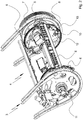
- the Fig. 1 shows, for example, a delivery 1 of a sheet-processing machine, here in particular a sheet-fed printing machine, specifically a sheet-fed offset rotary printing machine, preferably in aggregate and in-line construction.
- the machine is accordingly preferably operated in the offset process, with other printing processes, such as, for. B. screen printing, can be integrated in the machine.
- the sheets are gripped by gripper systems from rotating cylinders at the front edge and transferred between the cylinders in the gripper connection.
- the sheets are colored in a printing nip formed by a cylinder and a rubber cylinder with one printing ink each according to the motif.
- one or more coating units can be provided in which the sheets can be coated by a coating forme cylinder.
- the cylinders arranged in the machine can be single-sized or multiple-sized, a single-sized cylinder being able to accommodate at least one sheet and a double-sized cylinder being able to accommodate at least two sheets of maximum format on the circumferential side.
- the machine is preferably assigned a turning device for turning the sheets in a perfecting mode while the machine is running. Further can also processing facilities or processing plants, such. B. cold foil works, be integrated in the machine.
- the machine has a drive wheel train which, particularly preferably as a continuous drive wheel train, drives at least the sheet guide cylinders of the machine.
- Sheet guide cylinders designed as transfer drums or transfer cylinders are also preferably driven by the drive wheel train.
- the sheet guide cylinders on the drive side of the machine each have interlocking gears that form the drive gear train.
- the drive train is driven by at least one main drive motor, which drives the drive train at at least one input point.
- the blanket cylinders of the printing units are also driven from the drive train. Further rotating bodies or rollers of the machine or of the printing units can also be driven at least temporarily by the drive wheel train, and these can also be designed to be coupled to the drive wheel train.
- Plate cylinders of printing units can also be assigned to individual drives, in particular direct drives.
- Direct drives are in particular individual drives, the rotors of which are aligned and concentrically preferably attached directly to the associated cylinders.
- the plate cylinder in question is then tracked electronically and in an electronically synchronized manner to the blanket cylinder, which is preferably driven by the main drive motor via the drive wheel train.
- the plate cylinder and / or blanket cylinder can be assigned a rotary encoder, which can be connected to a control unit of the printing unit and / or the machine control.
- the plate cylinder (s) can also be driven from the main drive motor via the drive gear train.
- the current machine angle is preferably known to a control device of the machine, for example the machine control.
- the machine angle can be defined as the position of a cylinder in space.
- the machine angle can be derived or recorded from the main drive motor.
- a rotary encoder in particular a rotary encoder, can be assigned to a preferably rotating element of the machine, which feeds or provides rotary encoder signals to the control device, in particular the machine control.
- a sheet guide cylinder of the machine in particular a sheet guide cylinder after a turning device (not shown) and / or a sheet guide cylinder from a last work, can be assigned a rotary encoder, preferably designed as a rotary encoder.
- the rotary encoder can in particular be assigned to the last sheet guide cylinder of the machine arranged immediately in front of the delivery 1 and / or be connected to the control device and / or to a quality control device, for example to an inspection system.
- the sheet guide cylinder has an at least approximately closed cylinder jacket surface and is here in particular a printing cylinder 2 of a last printing unit.
- the sheet guide cylinder can also be a last cylinder in a coating or other processing unit.
- the pressure cylinder 2 is made twice as large here and contains two diametrically arranged gripper systems located in gripper channels. The leading edges of the sheet are clamped and thus fixed by these gripper systems for sheet transport.
- the sheet guide cylinder can also be designed to be single, triple or multiple sizes.
- the sheet conveying system is also arranged in the delivery 1, which in particular has endless, preferably continuously revolving driven and guided gripping devices for taking over and transporting the sheets.
- the gripping devices are preferred arranged on traction means and driven endlessly revolving via wheels and / or on deflection guides.
- the gripping devices are in particular arranged parallel to one another and evenly spaced between the traction means and are preferably designed as clamping grippers.
- the sheet conveying system here has, in particular, a chain conveying system 3 with circumferentially guided gripper carriages and a chain wheel shaft 4 assigned adjacent to the sheet guiding cylinder, in particular the printing cylinder 2.
- the chain conveyor system 3 contains here in particular on both sides of the frame of the display 1 on chain guide rails guided guide chains, on which and between which the gripper carriages are attached.
- Each gripper carriage contains a clamping gripper system which, for example, has grippers that are fixedly arranged on a movable gripper shaft and fixed gripper supports. A gripping movement for fixing a respective sheet leading edge can be controlled by rotating the gripper shaft.
- the gripper shaft of a gripper carriage can preferably be actuated by means of roller levers and cam rollers, particularly in the area of sheet transfer and in the area of sheet deposit by control cams.
- the sheets are taken over by the sheet guide cylinder, in particular the printing cylinder 2, from the gripper carriage of the chain conveyor system 3 and guided along a sheet conveying path in the sheet conveying direction BFR to a delivery stack 5.
- the gripping movements of the gripper carriages can be controlled preferably via the roller levers and cam rollers, especially in the area of sheet transfer in the transfer center from the sheet guide cylinder, in particular pressure cylinder 2, and in the area of the sheet deposit, especially above the delivery stack 5, by control cams.
- the sheets are transported in the delivery 1 exclusively at the leading edge of the sheet by the gripping devices, in particular the gripper carriages.
- the sheets are preferably guided on guide elements (not shown), for example sheet guide plates, it being possible for an air cushion to be formed between the sheet and the sheet guide plates.
- guide elements for example sheet guide plates
- an air cushion to be formed between the sheet and the sheet guide plates.
- the Contact-free sheet transport can take place in the front and back printing mode.
- one or more dryers and / or dusting devices can be provided on the sheet conveying path.
- the delivery stack 5 is preferably preceded by a sheet brake in the sheet conveying direction BFR, which takes over the sheets to be deposited from the gripper carriage and, after their release, decelerates them from machine speed to deposit speed. After the delay by the sheet brake, the sheets are aligned with leading edge stops, trailing edge stops and / or side edge stops (not shown) and deposited neatly on the delivery stack 5.
- the delivery stack 5 is preferably lowered by a stack lift drive (not shown) during the sheet depositing process in such a way that the delivery stack surface forms an at least approximately constant deposit level for the coming sheets.
- the sheet brake can, for example, contain at least two braking stations which are preferably arranged axially, that is to say transversely to the sheet conveying direction BFR, displaceably, in particular displaceably.
- the braking stations are placed in particular on a respective lateral, usually unprinted, sheet edge. In the case of other planned braking stations, these can be placed on pressure-free corridors and / or on adequately dried areas of paint. Braking stations that are not required can be deactivated and / or moved out of the area of the sheet format. Alternatively, follower grippers can also be used.
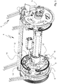
- the Fig. 2 shows a perspective view of the sprocket shaft 4, which is assigned directly adjacent to the last sheet guide cylinder of the machine.
- the chain wheel shaft 4 has a shaft which is arranged parallel to the axis of rotation of the adjacent sheet guide cylinder and to which chain wheels for the circulating chains of the chain conveyor system 3 are assigned on both sides.
- the chain wheels work with the respective chain guide rails to guide the gripper carriages in the Area of the sprocket shaft 4 together.
- the chain wheels are thus coaxially and spaced apart from one another, in particular permanently assigned to the chain wheel shaft 4.
- a drive is assigned to the sprocket shaft 4, which drives the sprocket shaft 4 in rotation about its axis of rotation in synchronism with the drive gear train.
- the sprocket shaft 4 here preferably carries a helical gearwheel which interacts with the drive of the machine or is driven by it.
- the helical gearwheel which is in particular permanently assigned to the sprocket shaft 4, is preferably part of the continuous drive gear train or gear train of the machine in meshing engagement with a gear of the sheet guiding cylinder immediately upstream, in particular of the printing cylinder 2.
- the chain wheel shaft 4 has between the two chain wheels at least two and preferably exactly two sheet support segments 6 for simultaneously supporting a sheet against the cylinder jacket surface of the sheet guide cylinder, in particular the printing cylinder 2. At least one and preferably both arch support segments 6 are axially displaceable with respect to the sprocket shaft 4, for example on a hub.
- each hub has exactly two arched support segments 6, which are arranged diametrically to one another and are firmly assigned to the hub.
- the hub can, for example, have rollers rolling on the surface of the shaft. It can be provided, for example, to assign six rollers to each hub, which run on preferably ground tracks of the sprocket shaft 4.
- an adjusting means is provided for the axial adjustment of the arch support segments 6.
- a drive for example an electrically operating drive motor, is preferred for one or for each hub, for example on the operating side, which acts on the respective hub preferably via a spindle drive and effects an axial adjustment of the hub or of the arched support segments 6 assigned to the hub.
- the axial adjustment of the sheet support segments 6 can be carried out together with the axial adjustment of the braking stations of the sheet brake to the sheet format.
- the axial adjustment can also be carried out and / or monitored in an automated manner on the basis of the same data by a control device, in particular the machine control.
- the sheet support segments 6 can preferably be moved so far apart that sheets of the maximum format to be processed can be supported on the respective lateral side edges of the sheet. It can further be provided that one or both sheet support segments 6 are displaced outside of the maximum sheet format in order, for example, to enable sheet transport without sheet support segments 6 or maintenance.
- the arch support segments 6 or the hubs can also be axially adjustable or displaceable or adjusted or displaced independently of one another.
- the drive motors for the axial adjustment of the hubs carrying the sheet support segments 6 can be controlled independently, for example, by the control device, in particular the machine control.
- the arch support segments 6 have recesses or their circumferential extent is dimensioned accordingly.
- a respective arch support segment 6 has a bracket 6, which is preferably held in a separate plane.
- a traction means carrying support elements, in particular a chain 8 carrying pressure elements 7, is assigned to the bracket 6 on the circumferential side.
- the bracket 6 contains a guide, oriented in the circumferential direction, for the traction means, in particular the chain 8, which can thus be displaced or displaced relative to the bracket 6 in the circumferential direction or in and / or against the sheet conveying direction BFR.
- the support elements assigned to the traction means, in particular the pressure elements 7 assigned to the chain 8 are accordingly mounted such that they can be displaced together in the circumferential direction along the bracket 6 or the guide of the bracket 6 when the traction means or chain 8 is displaced.
- a common displacement of the support elements, in particular pressure elements 7, in and / or against the sheet conveying direction BFR for adjustment, in particular for format adjustment, can thus take place.
- the support elements, in particular pressure elements 7, assigned to the traction means, in particular the chain 8, have a curved contact surface with a minimal axial extension.
- the axial extent of an arc contact surface can be, for example, 0.5 mm to 3 mm, preferably at least approximately 1 mm.
- the support elements, in particular pressure elements 7, preferably contain elastic material or are made of elastic material.
- the pressing elements 7 can in particular contain rubber or be made of rubber.
- the support elements, in particular pressure elements 7, viewed in the sheet conveying direction BFR can also have a wedge-shaped cross section or an increased sheet contact surface.
- the extension of the pressing elements 7 can be, for example, up to 50 mm.
- a sheet By means of a contact line of the support elements, in particular the sheet contact surfaces of the pressure elements 7, a sheet can be pressed against the cylinder jacket surface of the sheet guide cylinder, in particular pressure cylinder 2, and can thus be fixed or retained thereon. A sheet fall is thus avoided as long as the sheet is between the support elements, in particular pressure elements 7, and the sheet guide cylinder, in particular pressure cylinder 2.
- a sheet is preferably pressed against the cylinder jacket surface exclusively by the support elements, in particular pressure elements 7, and is not sucked in by the sheet support segments 6.
- the hub sleeve is preferably assigned a separate drive which can move the hub sleeve relative to the hub in the circumferential direction or in and / or against the sheet conveying direction BFR.
- the drive can, for example, be arranged directly on the hub or hub sleeve and displace the hub sleeve with respect to the hub.
- the hub can, for example, have an internally toothed tooth segment in which a pinion driven by the drive engages.
- the hub sleeve or the drive is correspondingly displaced axially along the shaft of the sprocket shaft 4 with the hub.
- the energy and / or signal transmission to the drive seated on the hub is preferably carried out by means of a rotary infeed 11 of the rotatably mounted sprocket shaft 4 is.
- the two drives, each assigned to a hub, are supplied from the cable chain.
- a sprocket shaft 4 and in particular a respective hub sleeve is assigned at least one fixing device for preferably pneumatically fixing a sheet trailing edge in areas.
- each hub sleeve carries exactly two fixing devices arranged diametrically to one another, which are preferably each firmly connected to the hub sleeve.
- the fixing devices can be placed on the respective sheet trailing edge in and / or against the sheet conveying direction BFR.
- the drive particularly preferably at the same time, moves the traction means associated with the arch support segment 6, in particular the bracket 6, in particular the chain 8.
- the traction means in particular the chain 8, is in particular also displaced in and / or against the sheet conveying direction BFR along the guide of the bracket 6.
- a respective fixing device is preferably connected to the traction means, in particular a chain link of the chain 8, in such a way that an adjustment movement of the fixing device simultaneously adjusts the traction means associated support elements, in particular the pressure elements 7 associated with the chain 8.
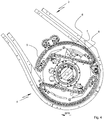
- the Fig. 3 shows a perspective view of the sprocket shaft 4 with support elements, in particular pressure elements 7, bearing arch support segments 6, in particular brackets 6, and fixing devices for the rear edge of the arch.
- the fixing devices are in particular arranged exclusively in the area of the arch support segments 6, in particular brackets 6, between the arch support segments 6, in particular brackets 6, with one fixing device in each case being assigned directly to an arch support segment 6, in particular bracket 6. Further fixing devices for the rear edge of the sheet between the two outer fixing devices fixing the rear corners of the sheet are not provided. In particular, precisely one fixing device is assigned to a respective arch support segment 6, in particular bracket 6.
- One fixing device is preferably in each case mounted directly adjacent to an arch support segment 6, in particular bracket 6, and / or movably mounted relative to an arch support segment 6, in particular bracket 6, in particular for adjustment.
- the fixing devices are designed to be format-adjustable in particular in the sheet longitudinal direction, ie in the sheet conveying direction BFR, and / or in the sheet width direction, ie transversely to the sheet conveying direction BFR.
- the fixing devices are preferably designed to be format-adjustable together with support elements, in particular pressure elements 7, of the arch support segments 6, in particular brackets 6.
- the fixing devices with the support elements, in particular pressure elements 7, can preferably be adjusted simultaneously or jointly by the drive seated on the hub.
- a respective fixing device for the sheet trailing edge contains a contact element which, preferably as a pneumatically acting suction device 10, fixes a limited area of the sheet trailing edge by suction.
- each fixing device, in particular each suction device 10 has a separate pneumatic device Connection, the pneumatic connections of the fixing devices, in particular suction devices 10, preferably being in pneumatic connection or flow connection with a common compressed air generator.
- the compressed air generator provides, in particular, a pneumatic pressure that is permanently above ambient pressure and / or is not clocked, which is accordingly available at the pneumatic connections of the fixing devices, in particular suction devices 10.
- a compressor for example, can be used as the compressed air generator.
- the pneumatic connection of the fixing devices, in particular suction devices 10 also takes place via a rotary inlet 11 of the rotatably mounted sprocket shaft 4, in particular with the implementation of a cable chain, for example in the center of the machine.
- the compressed air generator is here in particular connected to both laterally arranged fixing devices, in particular suction cups 10, which fix the sheet at the same time.
- the compressed air generator is in pneumatic or flow connection with all or exactly four fixing devices, in particular suction cups 10.
- a contact element of the fixing device has an at least approximately flat contact surface for an arched area.
- a suction device 10 has a suction surface which transmits a suction effect of the fixing device to the sheet.
- the pneumatically operating suction cups 10 of the fixing devices preferably each have at least one opening for generated suction air in the suction surface, through which a sheet is held in contact with the suction cup 10.
- each teat 10 can have a number of openings or suction openings, for example four to six suction openings.
- the fixing devices can also have, for example, exchangeable contact elements, in particular suction cups 10, which, for example, have differently arranged or designed openings or openings.
- the contact surface of a contact element or the suction surface of a suction cup 10 can extend, for example, up to 20 mm in Have sheet conveying direction BFR and / or by up to 50 mm transversely to the sheet conveying direction BFR.
- Each fixing device is preferably assigned an air control element, in particular immediately adjacent to the suction surface, which is preferably designed as a solenoid valve 13, particularly preferably as a quick-acting valve.
- the fixing devices could also have a separate holder, but are preferably assigned directly to the arch support segments 6, in particular brackets 6.
- the contact surfaces of the contact elements, in particular the suction surfaces of the suction devices 10, of the fixing devices are preferably always held at the level of the support elements, in particular the contact surfaces of the pressure elements 7, of the arch support segments 6.
- the contact elements, in particular suction cups 10 can be received by a fixing device via a lockable plug connection.
- a contact element, in particular suction cup 10 can be assigned to a receptacle of the fixing device in the axial direction, wherein the contact element, in particular suction cup 10, can be held fixable in its position by the fixing device, for example via a ball catch.
- contact elements in particular suction cups 10
- contact elements, in particular suction cups 10 of different material compositions and / or shapes of a fixing device can each be assigned interchangeably with one another.
- the contact elements, in particular suction cups 10 are assigned to the fixing devices so that they can be removed or replaced quickly or without tools.
- the Fig. 4 shows a side view of the, for example, double-sized sprocket shaft 4 with supporting elements 7 arranged on traction means, in particular pressing elements 7 arranged on chains 8 Bracket 6 out in the circumferential direction.
- the chain is on the inside 8 held in the desired or adjustable tension by a tensioning means, here in particular a tensioning roller 9.
- An adjusting means in particular a drive, preferably an electrically operating drive motor, is provided for displacing the chain 8 carrying the pressure elements 7 relative to the bracket 6 in and / or against the sheet conveying direction BFR, in particular for setting or setting the format.
- the chain 8 has chain links connected to one another in an articulated manner, to which the pressure elements 7 can be assigned. Exactly one pressure element 7 can be assigned to each chain link of the chain 8.
- the pressing elements 7 are preferably interchangeably assigned to the chain 8, wherein a respective pressing element 7 can be received by a chain link of the chain 8 in a form-fitting and / or force-fitting manner.
- a pressure element 7 is received by a chain link of the chain 8 via a lockable plug connection.
- a pressure element 7 is preferably received by a respective chain link of the chain 8 via a screw connection. In this way, differently designed pressure elements 7 can be assigned interchangeably to a respective chain link of a chain 8.
- pressing elements 7 of different material compositions and / or shapes can be assigned to a respective chain link of a chain 8 in such a way that they can be exchanged with one another.
- the pressure elements 7 are assigned to the chain 8 or to the arched support segments 6, in particular brackets 6, which can be quickly removed or exchanged.
- the Fig. 5 shows an enlarged view of a sheet support segment 6, in particular bracket 6, with pressure elements 7 assigned to a chain 8 and a fixing device for the sheet trailing edge.
- the fixing device has a compressed air connection connected to the compressed air generator and works according to the ejector principle.
- the fixing device contains in particular an ejector 12 which opens into an outlet channel. Via the outlet channel directed, for example, in the direction of the shaft leak stale air.
- deflection or diffusion means can be provided for the air emerging from the outlet duct.
- the fixing device preferably has an air control element, which is designed in particular as a solenoid valve 13.
- the air control element in particular solenoid valve 13, controls the suction effect of the respective fixing device, for example as a function of the machine speed and / or of the properties of the printing material.
- all fixing devices are preferably designed as ejector suckers.
- Each fixing device, in particular each suction device 10 is preferably assigned an air control element, in particular a remotely controllable solenoid valve 13, for the individual and / or remotely controllable control of the suction effect, the air control element, in particular the solenoid valve 13, in particular controlling the compressed air feeding the ejector 12.
- an air control element in particular a solenoid valve 13 of one or preferably each fixing device can be carried out by a control device, in particular the machine control.
- the electrical control connection is preferably also made via a rotary lead-in 11 of the rotatably mounted sprocket shaft 4 and, if necessary, a cable chain.
- an air control element, in particular solenoid valve 13 can be activated by the control device, in particular machine control, for the order-related setting of the pneumatic action of the fixing device, in particular of suction device 10.
- the air control element in particular the solenoid valve 13 be used to set or change the start, the intensity and / or the end of the pneumatic suction effect of the fixing device, in particular of the suction device 10.
- the setting or change can also be made while the machine is running or during the printing process.
- the air control element, in particular the solenoid valve 13 is particularly preferably used to influence or influence the suction effect of the fixing device, in particular of the suction device 10, depending on the machine speed and / or on the properties of the printing material. set.
- the air control element, in particular solenoid valve 13 can interact with the control device in such a way that the beginning, the intensity and / or the end of the pneumatic action can be set manually or automatically.
- a fixing device in particular a suction device 10
- the compressed air feeding the ejector 12 is controlled in such a way that the beginning, the intensity and / or the end of a suction effect is set.
- the setting of the suction air of the fixing device, in particular on the suction device 10, by the air control element, in particular solenoid valve 13, can also be carried out as a function of the sheet travel when the sheet is accepted and / or when the sheet is released.
- the sheet travel can therefore also be influenced or controlled or regulated individually and / or remotely during the printing process.
- An automated setting of the suction effect on the individual fixing devices, in particular suction cups 10, of the sprocket shaft 4 can be carried out, for example, according to sensor values.
- a dead time in building up the suction effect can be taken into account. This dead time can also be compensated for as a function of the speed, for example.
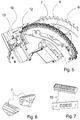
- the Fig. 6 shows an embodiment of a pressure element 7 for a chain 8 guided on a bracket 6.
- the pressure element 7 can be interchangeably assigned to a chain link of the chain 8 via a screw connection.
- the pressure element 7 is designed in particular to be elastic and has a contact surface for an arc that extends in the circumferential direction and has a minimal axial extent.
- the pressing element 7 can be made of rubber, for example. An elasticity of the pressure element 7 can be achieved in particular through the choice of material and / or a suitable shape.
- the Fig. 7 shows an embodiment of a contact element as a suction device 10 for a fixing device.
- the suction device 10 can be assigned to the fixing device, in particular the ejector 12, via a receptacle.
- the suction device 10 can have guide surfaces which are received or guided by guide surfaces of the fixing device.
- the suction cup 10 can be assigned to the fixing device in the axial direction, a lockable plug connection for fixing the position preferably being provided.
- At least one hemispherical recess for example, can be provided on the underside of the teat 10, which interacts positively with a spring-loaded locking ball of the fixing device to fix the position and thus enables the teat 10 to be changed or exchanged without tools.
- the suction cup 10 has at least one and here in particular four openings and forms the suction surface for the sheet trailing edge with centrally arranged supporting elevations.
- the suction cup 10 is preferably dimensioned such that its suction surface is always or permanently at the level of the contact line of the immediately adjacent support element, in particular the pressure element 7, of the arch support segment 6.
- An elastic cover such as a rubber cover, can also be assigned to the teat 10.
- the opening or openings of the suction cup 10 enable the effect of suction air generated by the ejector 12 in some areas on the sheet trailing edge, so that a suction force holds the sheet trailing edge in contact with the suction surface of the suction cup 10.
- the sheet support segments 6, in particular the bracket 6, can be placed axially on the side edges of the new sheet format.
- the fixing devices, in particular suction devices 10 can be placed on the rear edge of the sheet of the new sheet format, with the support elements, in particular pressing elements 7, preferably being displaced at the same time in such a way that only the respective Sheet side edge of the new sheet format is contacted by support elements, in particular pressure elements 7.
- suitable support elements, in particular pressure elements 7, can be assigned to the arch support segments 6, in particular brackets 6, and / or suitable contact elements, in particular suction cups 10, to the fixing devices.
- the sheet support segments 6, in particular brackets 6, or the support elements, in particular the pressure elements 7, simultaneously support or press a respective sheet against the cylinder jacket surface of the upstream sheet guide cylinder, in particular pressure cylinder 2, with a respective sheet trailing edge next to the sheet support segments 6, in particular brackets 6, or the support elements, in particular the pressure elements 7, in the area of the arch support segments 6, in particular brackets 6, or the support elements, in particular the pressure elements 7, is held and guided exclusively by the immediately adjacent fixing devices, in particular suction cups 10 .
- the suction air of the fixation devices is preferably obtained from compressed air from a compressed air generator according to the ejector principle, with air control elements, in particular solenoid valves 13, assigned to the fixation devices, in particular suction devices 10, controlling the suction air with precise timing. If necessary, the suction air control can also be changed individually and / or remotely. For example, the air control elements, in particular solenoid valves 13, can be activated according to characteristic curves. In this way, maximum suction power can be ensured during sheet transfer in the transfer center. Subsequently, the suction effect can be reduced as a function of the angle, for example, since a lower suction force is sufficient for holding the sheet trailing edge resting on the suction surface of the suction device 10.
Description
Die Erfindung betrifft eine bogenverarbeitende Maschine mit einer Bogentransportvorrichtung mit einem Bogen von einem Bogenführungszylinder übernehmenden Bogenfördersystem und ein Verfahren zum Transportieren von Bogen von einem Bogenführungszylinder an ein Bogenfördersystem in einer bogenverarbeitenden Maschine.The invention relates to a sheet processing machine with a sheet transport device with a sheet conveying system taking over a sheet from a sheet guiding cylinder and a method for conveying sheets from a sheet guiding cylinder to a sheet conveying system in a sheet processing machine.
Aus
Aus
Aus
Aus
Aus
Aus
Die Bogenhinterkante wird von einer über die maximale Formatbreite reichenden, Sauger aufweisenden Traverse gehalten. Nachteilig ist, dass die Traverse zur Übernahme der Bogenhinterkante groß und damit dynamisch ungünstig ist. Durch die Traverse wird die zur Verfügung stehende Bogenfläche reduziert und es treten hohe Leckageverluste auf. Aus der
Der Erfindung liegt die Aufgabe zugrunde, eine alternative bogenverarbeitende Maschine mit einer Bogentransportvorrichtung und ein alternatives Verfahren zum Bogentransport bereitzustellen. Insbesondere soll eine Bogenübergabe von einem Bogenführungszylinder an ein nachgeordnetes Bogenfördersystem weiter verbessert werden.The invention is based on the object of providing an alternative sheet processing machine with a sheet transport device and an alternative method for sheet transport. In particular, a sheet transfer from a sheet guide cylinder to a downstream sheet conveying system is to be further improved.
Erfindungsgemäß wird die Aufgabe durch eine Vorrichtung mit den Merkmalen des unabhängigen Vorrichtungsanspruchs und ein Verfahren mit den Merkmalen des unabhängigen Verfahrensanspruchs gelöst. Vorteilhafte Ausgestaltungen ergeben sich aus den Unteransprüchen, der Beschreibung und den Zeichnungen.According to the invention, the object is achieved by a device with the features of the independent device claim and a method with the features of the independent method claim. Advantageous refinements result from the subclaims, the description and the drawings.
Die Erfindung hat den Vorteil, dass eine alternative bogenverarbeitende Maschine mit einer Bogentransportvorrichtung und ein alternatives Verfahren zum Bogentransport bereitgestellt werden. Insbesondere wird eine Bogenübergabe von einem Bogenführungszylinder an ein nachgeordnetes Bogenfördersystem weiter verbessert. Eine Bogentransportvorrichtung kann innerhalb einer bogenverarbeitenden Maschine, beispielsweise einer Bogendruckmaschine, oder in einer Auslage einer bogenverarbeitenden Maschine, beispielsweise einer Bogendruckmaschine, eingesetzt werden. Ein Bogenfördersystem kann beispielsweise als Bogenführungstrommel ausgebildet sein und insbesondere zwischen zwei Druckzylindern einer Bogendruckmaschine angeordnet sein. Es wird entsprechend auch eine bogenverarbeitende Maschine, insbesondere eine Bogendruckmaschine, mit einer entsprechenden Bogentransportvorrichtung bereitgestellt. Bevorzugt enthält das Bogenfördersystem eine Auslagetrommel, die insbesondere in der Auslage einer bogenverarbeitenden Maschine eingesetzt wird. Die Auslagetrommel enthält dabei besonders bevorzugt eine Kettenradwelle, um die Greifeinrichtungen, insbesondere Greiferwagen eines Kettenfördersystems, zur Übernahme von Bogenvorderkanten bewegt werden.The invention has the advantage that an alternative sheet processing machine with a sheet transport device and an alternative method for sheet transport are provided. In particular, sheet transfer from a sheet guide cylinder to a downstream sheet conveying system is further improved. A sheet transport device can be used within a sheet processing machine, for example a sheet printing machine, or in a display of a sheet processing machine, for example a sheet printing machine. A sheet conveyor system can for example be designed as a sheet guide drum and in particular be arranged between two printing cylinders of a sheet-fed printing machine. There will be a accordingly sheet processing machine, in particular a sheet printing machine, provided with a corresponding sheet transport device. The sheet conveyor system preferably contains a delivery drum, which is in particular in the delivery of a sheet processing machine is used. The delivery drum particularly preferably contains a sprocket shaft around which the gripping devices, in particular the gripper carriage of a chain conveyor system, are moved to take over the leading edges of the sheet.
Beispielsweise beim Drucken an Bogendruckmaschinen werden auch in eigentlich druckfreien Bereichen geringe Mengen an Farbe von der Platte über den Gummizylinder auf den Druckzylinder übertragen. An Stellen, wo kein Bogen auf dem Druckzylinder aufliegt, verbleiben diese geringen Farbmengen auf dem Druckzylinder, wo sie sich über lange Zeit aufbauen können. Bei Waschprozessen können dies auch größere Mengen sein. Bogenstützsegmente, die sich ständig im Kontakt mit dem Druckzylinder befinden, verschmutzen mit der Zeit. Dies betrifft auch den hinteren Teil der Bogenstützsegmente, wenn nicht gerade Maximalformat gedruckt wird. Daher ist es vorteilhaft, die mit einem Bogen im Bereich einer Bogenführungstrommel oder Auslagetrommel in Kontakt kommenden Stützelemente bzw. Kontaktelemente formateinzustellen.For example, when printing on sheet-fed printing machines, small amounts of ink are transferred from the plate via the blanket cylinder to the printing cylinder, even in areas that are actually print-free. In places where there is no sheet on the impression cylinder, these small amounts of ink remain on the impression cylinder, where they can build up over a long period of time. In the case of washing processes, these can also be larger quantities. Sheet support segments that are constantly in contact with the impression cylinder become soiled over time. This also applies to the rear part of the sheet support segments, if the maximum format is not being printed. It is therefore advantageous to format the support elements or contact elements that come into contact with a sheet in the area of a sheet guide drum or delivery drum.
Bevorzugt erfolgt ein Saugen ausschließlich an der Bogenhinterkante bzw. an den hinteren Ecken. Damit können die seitlichen Bogenstützsegmente bzw. Stützelemente sehr schmal gestaltet werden, was wiederum zu vorteilhaften sehr schmalen druckfreien Seitenrändern führt. Beispielsweise können die Bogenstützsegmente im Zwischenraum zwischen Greiferwagen als Bügel ausgebildet sein bzw. Bügel tragen, um die ein Zugmittel, insbesondere eine Kette, geführt wird, welches zumindest teilweise mit bevorzugt elastischen Stützelementen besetzt wird, und zwar bevorzugt dergestalt, dass sich diese Elemente nur im Bereich der seitlichen Bogenränder zwischen Greiferwagen und Fixiereinrichtungen, insbesondere Saugern, befinden. Beim Verstellen einer Fixiereinrichtung, insbesondere eines Saugers, auf die korrekte Bogenlänge wird das Zugmittel, insbesondere die Kette, vorzugsweise mit verstellt. So können die überschüssigen Stützelemente beim Verfahren auf eine kleinere Formatlänge vorteilhaft in einem Bereich "gespeichert" werden, in dem sie keinen Kontakt mit dem Bogen haben.Sucking is preferably carried out exclusively at the rear edge of the sheet or at the rear corners. The lateral arch support segments or support elements can thus be made very narrow, which in turn leads to advantageous, very narrow, pressure-free side margins. For example, the arch support segments in the space between the gripper carriages can be designed as brackets or carry brackets around which a traction means, in particular a chain, is guided, which is at least partially covered with preferably elastic support elements, preferably in such a way that these elements are only in The area of the lateral sheet edges between the gripper carriage and fixing devices, in particular suction cups, are located. When adjusting a fixing device, in particular a suction device, to the correct arc length, the traction means, in particular the chain, is preferably also adjusted. In this way, when moving to a smaller format length, the excess support elements can advantageously be "stored" in an area in which they have no contact with the sheet.
Vorteilhafterweise werden die Stützelemente lediglich an den Stellen eingesetzt, wo sich zwischen diesen Stützelementen und der Zylindermantelfläche noch ein Bedruckstoff, insbesondere Papier, befindet. Die Stützelemente sind somit vor Verschmutzung geschützt.The support elements are advantageously only used at the points where there is still a printing material, in particular paper, between these support elements and the cylinder jacket surface. The support elements are thus protected from contamination.
Bevorzugt kontaktieren die Stützelemente ausschließlich Bedruckstoffmaterial und nie die verschmutzte Druckzylinderoberfläche eines Druckzylinders einer Bogendruckmaschine. Die gesamte Vorrichtung ist damit wesentlich weniger schmutzanfällig und damit wartungsarm. Besonders bevorzugt ergibt sich bei ausschließlich stützenden Bogenstützsegmenten die Möglichkeit, besonders schmale Stützelemente einzusetzen, wobei sich gezeigt hat, dass ein vorzugsweise pneumatisches Fixieren der Bogen an den seitlichen Bogenhinterkanten bzw. an den hinteren Ecken ausreichend ist. Insbesondere kann der von der Vorderkante bis zur Hinterkante an der Zylindermantelfläche fixierte bzw. gehaltene Bogen leicht von benachbart der Bogenstützsegmente angeordneten Fixiereinrichtungen übernommen werden.The support elements preferably only contact printing material and never the soiled printing cylinder surface of a printing cylinder of a sheet-fed printing press. The entire device is therefore much less susceptible to dirt and therefore requires little maintenance. In the case of exclusively supporting arch support segments, it is particularly preferable to use particularly narrow support elements, whereby it has been shown that a preferably pneumatic fixing of the arches on the lateral trailing sheet edges or at the rear corners is sufficient. In particular, the sheet fixed or held on the cylinder jacket surface from the front edge to the rear edge can easily be taken over by fixing devices arranged adjacent to the sheet support segments.
Insbesondere können die Bogenstützsegmente, insbesondere Stützelemente, die Funktion haben, den Bogen an den Bogenführungszylinder, insbesondere einen Druckzylinder, anzupressen und dadurch einen "Bogensturz" zu verhindern. Zum anderen kann der Bogen auf seinem Weg um die Bogenführungstrommel oder Auslagetrommel, insbesondere eine Kettenradwelle, auf diesen Bogenstützsegmenten, insbesondere Stützelementen, ausgestützt und auf der gewünschten Bahn beispielsweise nahe von Bogenleitblechen gehalten werden, so dass der Bogen keine Sekante beschreiben kann.In particular, the sheet support segments, in particular support elements, can have the function of pressing the sheet against the sheet guide cylinder, in particular a pressure cylinder, and thereby preventing a “sheet fall”. On the other hand, the sheet can be supported on its way around the sheet guide drum or delivery drum, in particular a sprocket shaft, on these sheet support segments, in particular support elements, and held on the desired path, for example near sheet guide plates, so that the sheet cannot describe a secant.
Besonders bevorzugt wird ein jeder Bogen an seiner Hinterkante in einer Übergabezentralen durch Fixiereinrichtungen, insbesondere pneumatische Sauger, erfasst, welche bevorzugt ausschließlich im Bereich der seitlichen Bogenstützsegmente angeordnet sind. Das zum Ansaugen erforderliche Vakuum wird dabei bevorzugt "vor Ort" mittels nach dem Ejektor-Prinzip arbeitenden Fixiereinrichtungen erzeugt. Insbesondere wird dabei Druckluft bevorzugt ungetaktet über eine Dreheinführung einer rotierbar gelagerten Welle von Bogenführungstrommel oder Auslagetrommel, insbesondere eine Dreheinführung einer Kettenradwelle, übertragen. Nahe der Wirkstellen der Fixiereinrichtungen, insbesondere an den Bogenecken, befindet sich beispielsweise je ein Magnetventil, vorzugsweise ein Schnellschaltventil, welches über eine möglichst kurze Leitung mit einem Vakuumejektor verbunden ist. Dieser sitzt möglichst nah am Sauger bzw. ist in die Saugerbaugruppe integriert, um das zu evakuierende Totvolumen möglichst gering zu halten. Vorteilhafterweise werden dadurch Leckageverluste verringert bzw. vermieden, was zu einem geringeren Energieeinsatz führt (obwohl die Vakuumerzeugung durch Druckluft eigentlich energieintensiver ist als eine Erzeugung durch eine Pumpe). Weiterhin vorteilhaft sind der Wegfall der aufwändigen Baugruppe der Drehschieber und die zur Verfügungstellung einer praktisch verschleißfreien Lösung. Durch geringe Totvolumina nach dem Magnetventil sowohl in der Druck- als auch in der Saugleitung kann ein hochdynamisches Verhalten erzielt werden. Weiterhin vorteilhaft können die Zu- und/oder Abschaltzeitpunkte in Abhängigkeit von Bogengeschwindigkeit und/oder Bedruckstoff beispielsweise über die Maschinensoftware eingestellt bzw. verändert werden.Particularly preferably, each sheet is captured at its rear edge in a transfer center by fixing devices, in particular pneumatic suction devices, which are preferably arranged exclusively in the area of the lateral sheet support segments. The vacuum required for suction is preferably generated "on site" by means of fixing devices working according to the ejector principle. In particular compressed air is preferably not clocked via a rotary inlet of a rotatably mounted shaft of the sheet guide drum or delivery drum, in particular a rotary inlet of a sprocket shaft. For example, a solenoid valve, preferably a quick-acting valve, which is connected to a vacuum ejector via a line that is as short as possible is located near the active points of the fixing devices, in particular at the corners of the sheet. This sits as close as possible to the suction device or is integrated into the suction device assembly in order to keep the dead volume to be evacuated as low as possible. Advantageously, leakage losses are thereby reduced or avoided, which leads to a lower energy consumption (although the generation of a vacuum by compressed air is actually more energy-intensive than generation by a pump). The elimination of the complex assembly of the rotary valve and the availability of a practically wear-free solution are also advantageous. A highly dynamic behavior can be achieved through small dead volumes after the solenoid valve both in the pressure and in the suction line. The switch-on and / or switch-off times can also advantageously be set or changed as a function of sheet speed and / or printing material, for example via the machine software.
Beispielsweise können die Bogen von einem rotierenden Bogenführungszylinder an umlaufende Greifeinrichtungen, insbesondere Greiferwagen, und eine Auslagetrommel aufweisendes Bogenfördersystem übergeben werden. Die Auslagetrommel des Bogenfördersystems weist dabei bevorzugt benachbart zum Bogenführungszylinder angeordnete umlaufend, insbesondere rotierend, angetriebene Bogenstützsegmente auf, die insbesondere Aussparungen für die Greiferwagen aufweisen. Die Bogenstützsegmente bilden mit der Zylindermantelfläche des vorgeordneten Bogenführungszylinders eine Übergabezentrale, in der die Greiferwagen die Bogenvorderkanten im Greiferschluss von Greifersystemen des Bogenführungszylinders übernehmen. Die Bogenstützsegmente weisen insbesondere eine gegenüber der Zylinderbreite geringe axiale Erstreckung auf. Weiter können auch pneumatische Mittel vorgesehen sein, die die Bogen auf die Zylindermantelfläche drücken und/oder die die Bogen nach der Übergabezentralen an den Bogenstützsegmenten halten bzw. gegen die Bogenstützsegmente drücken.For example, the sheets can be transferred from a rotating sheet guide cylinder to rotating gripping devices, in particular gripper trolleys, and a sheet conveying system having a delivery drum. The delivery drum of the sheet conveying system preferably has circumferential, in particular rotating, driven sheet support segments which are arranged adjacent to the sheet guide cylinder and which in particular have recesses for the gripper carriages. The sheet support segments together with the cylinder jacket surface of the upstream sheet guide cylinder form a transfer center in which the gripper carriages take over the sheet leading edges in the gripper connection from the gripper systems of the sheet guide cylinder. The arch support segments in particular have a small axial extent compared to the cylinder width. Pneumatic means can also be used be provided which press the sheet onto the cylinder jacket surface and / or which hold the sheet after the transfer center on the sheet support segments or press against the sheet support segments.
Beispielsweise können die Bogen durch genau zwei Bogenstützsegmente gleichzeitig in der Übergabezentralen gegen die Mantelfläche des vorgeordneten Bogenführungszylinders gedrückt werden. Unterhalb der Bogenstützsegmente kann dabei ein Bogenleitelement angeordnet werden, welches bevorzugt mit einem Kammelement weit in den Bereich der Übergabezentralen reicht, wobei bevorzugt im Bogenleitelement Stützblasbohrungen angeordnet sind. Bevorzugt können die Stützblasbohrungen im mittleren Bereich des Bogenleitelementes über die Maschinenbreite in einer hohen Dichte und in den angrenzenden Bereichen, insbesondere in den in Bogenförderrichtung vor- und/oder nachgelagerten Bereichen, in einer gegenüber dem mittleren Bereich geringeren Dichte angeordnet sein. Die Blasluft des Bogenleitelementes könnte auch gemäß dem Fortschritt der Bogenübergabe variiert oder getaktet werden oder gesteuert oder nach Sensorwerten geregelt sein. Besonders bevorzugt kann ein Bogentransport von einem Bogenführungszylinder eines letzten Werkes an ein Bogenfördersystem in der Auslage einer bogenverarbeitenden Maschine vorgesehen sein, wobei ein Bogenleitelement unterhalb der Auslagetrommel vorgesehen sein kann.For example, the sheets can be pressed against the outer surface of the upstream sheet guide cylinder at the same time in the transfer center by exactly two sheet support segments. Below the sheet support segments, a sheet guide element can be arranged, which preferably with a comb element extends far into the area of the transfer centers, with support blow holes preferably being arranged in the sheet guide element. The support blow holes can preferably be arranged in the middle area of the sheet guiding element across the machine width in a high density and in the adjacent areas, in particular in the areas upstream and / or downstream in the sheet conveying direction, in a lower density compared to the middle area. The blown air of the sheet guiding element could also be varied or clocked or controlled or regulated according to sensor values in accordance with the progress of the sheet transfer. Particularly preferably, a sheet transport from a sheet guide cylinder of a last work to a sheet conveyor system in the delivery of a sheet processing machine can be provided, with a sheet guide element being provided below the delivery drum.
Im Folgenden soll die Erfindung beispielhaft erläutert werden. Die dazugehörigen Zeichnungen stellen dabei schematisch dar:
- Fig. 1:
- Auslage einer bogenverarbeitenden Maschine mit einer Kettenradwelle;
- Fig. 2:
- Perspektivische Darstellung der Kettenradwelle mit verstellbaren Bogenstützsegmenten;
- Fig. 3:
- Perspektivische Darstellung der Kettenradwelle mit Stützelemente tragenden Bogenstützsegmenten und Fixiereinrichtungen für die Bogenhinterkante;
- Fig. 4:
- Seitliche Ansicht der doppeltgroßen Kettenradwelle mit an Ketten angeordneten Andrückelementen;
- Fig. 5:
- Vergrößerte Ansicht eines Bogenstützsegmentes mit Andrückelementen und einem Sauger für die Bogenhinterkante;
- Fig. 6:
- Ausführung eines Andrückelementes für eine auf einem Bügel geführte Kette;
- Fig. 7:
- Ausführung eines Kontaktelementes als Sauger für eine Fixiereinrichtung.
- Fig. 1:
- Delivery of a sheet processing machine with a sprocket shaft;
- Fig. 2:
- Perspective view of the sprocket shaft with adjustable arch support segments;
- Fig. 3:
- Perspective view of the sprocket shaft with sheet support segments carrying support elements and fixing devices for the sheet trailing edge;
- Fig. 4:
- Side view of the double-sized sprocket shaft with pressure elements arranged on chains;
- Fig. 5:
- Enlarged view of a sheet support segment with pressure elements and a sucker for the sheet trailing edge;
- Fig. 6:
- Execution of a pressure element for a chain guided on a bracket;
- Fig. 7:
- Execution of a contact element as a suction cup for a fixing device.
Die
Insbesondere weist die Maschine einen Antriebsräderzug auf, der besonders bevorzugt als durchgehender Antriebsräderzug zumindest die Bogenführungszylinder der Maschine antreibt. Bevorzugt werden auch als Übergabetrommeln bzw. Transferzylinder ausgeführte Bogenführungszylinder durch den Antriebsräderzug angetrieben. Dafür weisen die Bogenführungszylinder auf der Antriebsseite der Maschine jeweils ineinandergreifende Zahnräder auf, die den Antriebsräderzug bilden. Der Antriebsräderzug wird von mindestens einem Hauptantriebsmotor angetrieben, welcher an mindestens einer Eintriebstelle in den Antriebsräderzug eintreibt. Bevorzugt werden auch Gummizylinder der Druckwerke vom Antriebsräderzug aus angetrieben. Weitere Rotationskörper oder Walzen der Maschine bzw. der Druckwerke können ebenfalls zumindest zeitweise vom Antriebsräderzug angetrieben sein, wobei diese auch an den Antriebsräderzug kuppelbar ausgebildet sein können.In particular, the machine has a drive wheel train which, particularly preferably as a continuous drive wheel train, drives at least the sheet guide cylinders of the machine. Sheet guide cylinders designed as transfer drums or transfer cylinders are also preferably driven by the drive wheel train. For this purpose, the sheet guide cylinders on the drive side of the machine each have interlocking gears that form the drive gear train. The drive train is driven by at least one main drive motor, which drives the drive train at at least one input point. Preferably, the blanket cylinders of the printing units are also driven from the drive train. Further rotating bodies or rollers of the machine or of the printing units can also be driven at least temporarily by the drive wheel train, and these can also be designed to be coupled to the drive wheel train.
Plattenzylindern von Druckwerken können auch Einzelantriebe, insbesondere Direktantriebe, zugeordnet sein. Direktantriebe sind dabei insbesondere Einzelantriebe, deren Rotoren fluchtend und konzentrisch bevorzugt unmittelbar zu den zugeordneten Zylindern angebracht sind. Während des Druckens wird der betreffende Plattenzylinder dann dem bevorzugt über den Antriebsräderzug vom Hauptantriebsmotor angetriebenen Gummizylinder elektronisch synchronisiert nachgeführt. Dafür kann dem Plattenzylinder und/oder Gummizylinder ein Drehgeber zugeordnet sein, welche mit einer Steuereinheit des Druckwerkes und/oder der Maschinensteuerung verbunden sein können. Alternativ kann der Antrieb des oder der Plattenzylinder aber auch über den Antriebsräderzug vom Hauptantriebsmotor aus erfolgen.Plate cylinders of printing units can also be assigned to individual drives, in particular direct drives. Direct drives are in particular individual drives, the rotors of which are aligned and concentrically preferably attached directly to the associated cylinders. During printing, the plate cylinder in question is then tracked electronically and in an electronically synchronized manner to the blanket cylinder, which is preferably driven by the main drive motor via the drive wheel train. For this purpose, the plate cylinder and / or blanket cylinder can be assigned a rotary encoder, which can be connected to a control unit of the printing unit and / or the machine control. Alternatively, the plate cylinder (s) can also be driven from the main drive motor via the drive gear train.
Einer Steuereinrichtung der Maschine, beispielsweise der Maschinensteuerung, ist bevorzugt der jeweils aktuelle Maschinenwinkel bekannt. Der Maschinenwinkel kann dabei als Lage eines Zylinders im Raum definiert sein. Beispielsweise kann der Maschinenwinkel vom Hauptantriebsmotor abgeleitet oder aufgenommen werden. Es kann alternativ oder zusätzlich auch ein Drehgeber, insbesondere ein Drehwinkelgeber, einem vorzugsweise rotierenden Element der Maschine zugeordnet sein, welcher Drehgebersignale der Steuereinrichtung, insbesondere der Maschinensteuerung, zuführt bzw. für diese bereitstellt. Beispielsweise kann einem Bogenführungszylinder der Maschine, insbesondere einem Bogenführungszylinder nach einer nicht gezeigten Wendeeinrichtung und/oder einem Bogenführungszylinder eines letzten Werkes, ein Drehgeber, bevorzugt als Drehwinkelgeber ausgebildet, zugeordnet sein. Der Drehwinkelgeber kann insbesondere dem letzten unmittelbar vor der Auslage 1 angeordneten Bogenführungszylinder der Maschine zugeordnet sein und/oder mit der Steuereinrichtung und/oder mit einer Qualitätskontrolleinrichtung, beispielsweise mit einem Inspektionssystem, verbunden sein.The current machine angle is preferably known to a control device of the machine, for example the machine control. The machine angle can be defined as the position of a cylinder in space. For example, the machine angle can be derived or recorded from the main drive motor. Alternatively or additionally, a rotary encoder, in particular a rotary encoder, can be assigned to a preferably rotating element of the machine, which feeds or provides rotary encoder signals to the control device, in particular the machine control. For example, a sheet guide cylinder of the machine, in particular a sheet guide cylinder after a turning device (not shown) and / or a sheet guide cylinder from a last work, can be assigned a rotary encoder, preferably designed as a rotary encoder. The rotary encoder can in particular be assigned to the last sheet guide cylinder of the machine arranged immediately in front of the
Von einer bogenverarbeitenden Maschine, beispielsweise Bogendruckmaschine, ist ein letzter hier doppeltgroßer Bogenführungszylinder und ein Bogen von diesem übernehmendes Bogenfördersystem der Auslage 1 dargestellt. Der Bogenführungszylinder weist eine zumindest annähernd geschlossene Zylindermantelfläche auf und ist hier insbesondere ein Druckzylinder 2 eines letzten Druckwerkes. Alternativ kann der Bogenführungszylinder auch ein letzter Zylinder in einem Lack- oder sonstigen Bearbeitungswerk sein. Der Druckzylinder 2 ist hier doppeltgroß ausgeführt und enthält zwei diametral angeordnete in Greiferkanälen liegende Greifersysteme. Von diesen Greifersystemen werden die Bogenvorderkanten für einen Bogentransport geklemmt und damit fixiert. Alternativ kann der Bogenführungszylinder aber auch einfach-, dreifach- oder mehrfachgroß ausgeführt sein.From a sheet-processing machine, for example sheet-fed printing press, a last double-sized sheet guide cylinder and a sheet conveying system of the
In der Auslage 1 ist weiterhin das Bogenfördersystem angeordnet, welches insbesondere endlos bevorzugt kontinuierlich umlaufend angetriebene und geführte Greifeinrichtungen zur Übernahme und Transport der Bogen aufweist. Die Greifeinrichtungen sind bevorzugt an Zugmitteln angeordnet und über Räder und/oder an Umlenkführungen endlos umlaufend angetrieben. Die Greifeinrichtungen sind insbesondere parallel zueinander und gleichmäßig beabstandet zwischen den Zugmitteln angeordnet und bevorzugt als Klemmgreifer ausgeführt. Das Bogenfördersystem weist hier insbesondere ein Kettenfördersystem 3 mit umlaufend geführten Greiferwagen und eine dem Bogenführungszylinder, insbesondere dem Druckzylinder 2, benachbart zugeordnete Kettenradwelle 4 auf. Das Kettenfördersystem 3 enthält hier insbesondere an beiden Seiten des Gestells der Auslage 1 an Kettenführungsschienen geführten Führungsketten, an denen und zwischen denen die Greiferwagen befestigt sind. Jeder Greiferwagen enthält ein Klemmgreifersystem, welches beispielsweise fest an einer bewegbaren Greiferwelle angeordnete Greifer und feststehende Greiferaufschläge aufweist. Über eine Verdrehung der Greiferwelle kann eine Greifbewegung zum Fixieren einer jeweiligen Bogenvorderkante gesteuert werden. Bevorzugt über Rollenhebel und Kurvenrollen kann die Greiferwelle eines Greiferwagens insbesondere im Bereich der Bogenübernahme und im Bereich der Bogenablage von Steuerkurven betätigt werden.The sheet conveying system is also arranged in the
Von den Greiferwagen des Kettenfördersystems 3 werden die Bogen vom Bogenführungszylinder, insbesondere Druckzylinder 2, übernommen und entlang eines Bogenförderweges in Bogenförderrichtung BFR zu einem Auslagestapel 5 geführt. Bevorzugt über die Rollenhebel und Kurvenrollen können die Greifbewegungen der Greiferwagen insbesondere im Bereich der Bogenübernahme in der Übergabezentralen vom Bogenführungszylinder, insbesondere Druckzylinder 2, und im Bereich der Bogenablage, insbesondere oberhalb des Auslagestapels 5, von Steuerkurven gesteuert werden. Besonders bevorzugt erfolgt der Bogentransport in der Auslage 1 ausschließlich an der Bogenvorderkante durch die Greifeinrichtungen, insbesondere die Greiferwagen. Auf dem Bogenförderweg vom Bogenführungszylinder, insbesondere Druckzylinder 2, zum Auslagestapel 5 werden die Bogen bevorzugt an nicht dargestellten Leitelementen, beispielsweise Bogenleitblechen, geführt, wobei zwischen Bogen und den Bogenleitblechen auch ein Luftkissen ausgebildet sein kann. Insbesondere in der Betriebsart Schön- und Widerdruck kann ein berührungsfreier Bogentransport erfolgen. Auf dem Bogenförderweg können beispielsweise ein oder mehrere Trockner und/oder Bestäubungseinrichtungen vorgesehen sein.The sheets are taken over by the sheet guide cylinder, in particular the
In der Auslage 1 ist dem Auslagestapel 5 in Bogenförderrichtung BFR bevorzugt eine Bogenbremse vorgeordnet, die die abzulegenden Bogen von den Greiferwagen übernimmt und nach deren Freigabe von Maschinengeschwindigkeit auf Ablagegeschwindigkeit verzögert. Nach der Verzögerung durch die Bogenbremse werden die Bogen an nicht dargestellten Vorderkantenanschlägen, Hinterkantenanschlägen und/oder Seitenkantenanschlägen ausgerichtet und sauber auf dem Auslagestapel 5 abgelegt. Der Auslagestapel 5 wird bevorzugt von einem nicht dargestellten Stapelhubantrieb während des Bogenablageprozesses derart abgesenkt, dass die Auslagestapeloberfläche ein zumindest annähernd konstantes Ablageniveau für die kommenden Bogen bildet. Die Bogenbremse kann beispielsweise mindestens zwei Bremsstationen enthalten, welche bevorzugt axial, also quer zur Bogenförderrichtung BFR, verlagerbar, insbesondere verschiebbar, angeordnet sind. Die Bremsstationen werden insbesondere auf einen jeweiligen seitlichen in der Regel unbedruckten Bogenrand gestellt. Bei weiteren vorgesehenen Bremsstationen können diese auf druckfreie Korridore und/oder auf ausreichend getrocknete Farbbereiche gestellt werden. Nicht benötigte Bremsstationen können deaktiviert und/oder aus dem Bereich des Bogenformates verlagert werden. Alternativ können aber auch Nachgreifer eingesetzt werden.In the
Die
Die Kettenradwelle 4 weist zwischen den beiden Kettenrädern mindestens zwei und bevorzugt genau zwei Bogenstützsegmente 6 zum gleichzeitigen Stützen eines Bogens gegen die Zylindermantelfläche des Bogenführungszylinders, insbesondere Druckzylinders 2, auf. Mindestens eines und bevorzugt beide Bogenstützsegmente 6 sind axial verlagerbar gegenüber der Kettenradwelle 4 beispielsweise auf einer Nabe gelagert. In der doppeltgroßen Ausführung der Kettenradwelle 4 weist beispielsweise jede Nabe genau zwei Bogenstützsegmente 6 auf, die diametral zueinander angeordnet fest der Nabe zugeordnet sind. Durch die gemeinsame Lagerung der Bogenstützsegmente 6 auf einer axial gegenüber der Welle der Kettenradwelle 4 verlagerbaren Nabe erfolgt eine gemeinsame Verstellung der Bogenstützsegmente 6 der jeweiligen Seite. Die Nabe kann beispielsweise an der Oberfläche der Welle abrollende Rollen aufweisen. Dabei kann vorgesehen sein jeder Nabe beispielsweise sechs Rollen zuzuordnen, die auf bevorzugt geschliffenen Bahnen der Kettenradwelle 4 laufen. Zur Axialverstellung der Bogenstützsegmente 6 ist insbesondere ein Stellmittel vorgesehen. Bevorzugt ist ein oder für jede Nabe ein Antrieb, beispielsweise ein elektrisch arbeitender Antriebsmotor, beispielsweise auf der Bedienseite, vorgesehen, welcher bevorzugt über einen Spindelantrieb an der jeweiligen Nabe angreift und eine Axialverstellung der Nabe bzw. der der Nabe zugeordneten Bogenstützsegmente 6 bewirkt. Beispielsweise kann die axiale Verstellung der Bogenstützsegmente 6 gemeinsam mit der Axialverstellung der Bremsstationen der Bogenbremse auf das Bogenformat vorgenommen werden. Die Axialverstellung kann weiterhin auf Grundlage derselben Daten durch eine Steuereinrichtung, insbesondere die Maschinensteuerung, automatisiert vorgenommen und/oder überwacht werden.The
Die Bogenstützsegmente 6 sind bevorzugt derart weit auseinander fahrbar, dass Bogen maximal zu verarbeitenden Formates an den jeweiligen seitlichen Bogenseitenrändern abgestützt werden können. Weiter kann es vorgesehen sein, ein oder beide Bogenstützsegmente 6 nach außerhalb des maximalen Bogenformates zu verlagern um beispielsweise einen Bogentransport ohne Bogenstützsegmente 6 oder eine Wartung zu ermöglichen. Es können dabei auch die Bogenstützsegmente 6 bzw. die Naben unabhängig voneinander axial verstellbar oder verlagerbar sein bzw. verstellt oder verlagert werden. Die Antriebsmotoren zur Axialverstellung der die Bogenstützsegmente 6 tragenden Naben sind dafür beispielsweise von der Steuereinrichtung, insbesondere Maschinensteuerung, unabhängig ansteuerbar. Für die umlaufenden Greiferwagen des Kettenfördersystems 3 weisen die Bogenstützsegmente 6 Aussparungen auf bzw. ist deren Umfangsausdehnung entsprechend dimensioniert.The
Beispielsweise weist ein jeweiliges Bogenstützsegment 6 einen Bügel 6 auf, welcher bevorzugt in separater Ebene gehalten wird. Dem Bügel 6 ist umfangsseitig ein Stützelemente tragendes Zugmittel, insbesondere eine Andrückelemente 7 tragende Kette 8, zugeordnet. Der Bügel 6 enthält eine in Umfangsrichtung orientierte Führung für das Zugmittel, insbesondere die Kette 8, welches damit in Umfangsrichtung bzw. in und/oder entgegen der Bogenförderrichtung BFR gegenüber dem Bügel 6 verlagert bzw. verschoben werden kann. Die dem Zugmittel zugeordneten Stützelemente, insbesondere die der Kette 8 zugeordneten Andrückelemente 7, sind entsprechend bei Verlagerung von Zugmittel bzw. Kette 8 gemeinsam in Umfangsrichtung entlang des Bügels 6 bzw. der Führung des Bügels 6 verlagerbar gelagert. Damit kann eine gemeinsame Verlagerung der Stützelemente, insbesondere Andrückelemente 7, in und/oder entgegen der Bogenförderrichtung BFR zur Einstellung, insbesondere zur Formateinstellung, erfolgen.For example, a respective
Die dem Zugmittel, insbesondere der Kette 8, zugeordneten Stützelemente, insbesondere Andrückelemente 7, weisen eine Bogenkontaktfläche mit minimaler axialer Erstreckung auf. Die axiale Erstreckung einer Bogenkontaktfläche kann beispielsweise 0,5 mm bis 3 mm, bevorzugt zumindest annähernd 1 mm, betragen. Die Stützelemente, insbesondere Andrückelemente 7, enthalten bevorzugt elastisches Material bzw. sind aus elastischem Material gefertigt. Die Andrückelemente 7 können insbesondere Gummi enthalten oder aus Gummi hergestellt sein. Beispielsweise können die Stützelemente, insbesondere Andrückelemente 7, in Bogenförderrichtung BFR gesehen auch einen keilförmigen Querschnitt oder eine erhöhte Bogenkontaktfläche aufweisen. In Umfangsrichtung bzw. entlang der Bogenförderrichtung BFR kann die Erstreckung der Andrückelemente 7 beispielsweise bis zu 50 mm betragen. Durch eine Kontaktlinie der Stützelemente, insbesondere der Bogenkontaktflächen der Andrückelemente 7, ist ein Bogen gegen die Zylindermantelfläche des Bogenführungszylinders, insbesondere Druckzylinders 2, pressbar und damit auf dieser fixierbar bzw. haltbar. Ein Bogensturz wird damit vermieden, so lange sich der Bogen zwischen den Stützelementen, insbesondere Andrückelementen 7, und dem Bogenführungszylinder, insbesondere Druckzylinder 2, befindet. Bevorzugt wird ein Bogen ausschließlich durch die Stützelemente, insbesondere Andrückelemente 7, gegen die Zylindermantelfläche gepresst und nicht durch Bogenstützsegmente 6 angesaugt.The support elements, in
Eine hier beispielsweise zwei jeweilige Bogenstützsegmente 6 tragende Nabe der Kettenradwelle 4 weist insbesondere weiterhin eine in Umfangsrichtung bewegbare Nabenhülse auf, welche bevorzugt auf der Nabe rotationsbeweglich gelagert ist. Der Nabenhülse ist bevorzugt ein separater Antrieb zugeordnet, der die Nabenhülse gegenüber der Nabe in Umfangsrichtung bzw. in und/oder entgegen der Bogenförderrichtung BFR verlagern kann. Der Antrieb kann beispielsweise direkt auf der Nabe oder Nabenhülse angeordnet sein und die Nabenhülse gegenüber der Nabe verlagern. Die Nabe kann beispielsweise ein innenverzahntes Zahnsegment aufweisen, in welches ein durch den Antrieb angetriebenes Ritzel eingreift. Die Nabenhülse bzw. der Antrieb wird entsprechend mit der Nabe axial entlang der Welle der Kettenradwelle 4 verlagert. Bevorzugt erfolgt die Energie- und/oder Signalübertragung zu dem auf der Nabe sitzenden Antrieb mittels einer Dreheinführung 11 der rotationsbeweglich gelagerten Kettenradwelle 4. Beispielsweise erfolgt eine Kabelführung im Innenraum der Kettenradwelle 4 bis ca. zur Maschinenmitte, wo insbesondere eine Kabelschleppe zur Speicherung der Kabel vorgesehen ist. Von der Kabelschleppe aus erfolgt eine Versorgung der beiden jeweils einer Nabe zugeordneten Antriebe.A hub of the
Bevorzugt ist einer Kettenradwelle 4 und insbesondere einer jeweiligen Nabenhülse mindestens eine Fixiereinrichtung zum vorzugsweisen pneumatischen bereichsweisen Fixieren einer Bogenhinterkante zugeordnet. Bei der doppeltgroßen Ausführung der Kettenradwelle 4 trägt jede Nabenhülse genau zwei diametral zueinander angeordnete Fixiereinrichtungen, welche bevorzugt jeweils fest mit der Nabenhülse verbunden sind. Durch einen eine jeweilige Nabenhülse gegenüber der Nabe verlagernden Antrieb können die Fixiereinrichtungen in und/oder entgegen der Bogenförderrichtung BFR auf die jeweilige Bogenhinterkante gestellt werden. Durch den Antrieb wird besonders bevorzugt gleichzeitig das dem Bogenstützsegment 6, insbesondere dem Bügel 6, zugeordnete Zugmittel, insbesondere die Kette 8, mit bewegt. Das Zugmittel, insbesondere die Kette 8, wird insbesondere ebenfalls in und/oder entgegen der Bogenförderrichtung BFR entlang der Führung des Bügels 6 verlagert. Bevorzugt ist eine jeweilige Fixiereinrichtung derart mit dem Zugmittel, insbesondere einem Kettenglied der Kette 8, verbunden, dass eine Verstellbewegung der Fixiereinrichtung gleichzeitig eine Verstellung der dem Zugmittel zugeordneten Stützelemente, insbesondere der der Kette 8 zugeordneten Andrückelemente 7, bewirkt.Preferably, a
Die
Insbesondere enthält eine jeweilige Fixiereinrichtung für die Bogenhinterkante ein Kontaktelement, welches bevorzugt als pneumatisch wirkender Sauger 10 einen begrenzten Bereich der Bogenhinterkante saugend fixiert. Insbesondere weist jede Fixiereinrichtung, insbesondere jeder Sauger 10, einen separaten pneumatischen Anschluss auf, wobei die pneumatischen Anschlüsse der Fixiereinrichtungen, insbesondere Sauger 10, bevorzugt mit einem gemeinsamen Drucklufterzeuger in pneumatischer Verbindung bzw. Strömungsverbindung stehen. Der Drucklufterzeuger stellt insbesondere einen dauerhaft über Umgebungsdruck liegenden und/oder ungetakteten pneumatischen Druck bereit, der entsprechend an den pneumatischen Anschlüssen der Fixiereinrichtungen, insbesondere Sauger 10, zur Verfügung steht. Als Drucklufterzeuger kann beispielsweise ein Kompressor eingesetzt werden. Besonders bevorzugt erfolgt der pneumatische Anschluss der Fixiereinrichtungen, insbesondere Sauger 10, ebenfalls über eine Dreheinführung 11 der rotierbar gelagerten Kettenradwelle 4, insbesondere unter Realisierung einer Kabelschleppe beispielsweise in der Maschinenmitte. Der Drucklufterzeuger steht hier insbesondere mit beiden seitlich angeordneten den Bogen gleichzeitig fixierenden Fixiereinrichtungen, insbesondere Saugern 10, in Verbindung. Bei der doppeltgroßen Auslagetrommel, insbesondere Kettenradwelle 4, steht der Drucklufterzeuger mit allen bzw. genau vier Fixiereinrichtungen, insbesondere Saugern 10, in pneumatischer Verbindung bzw. Strömungsverbindung.In particular, a respective fixing device for the sheet trailing edge contains a contact element which, preferably as a pneumatically acting
Ein Kontaktelement der Fixiereinrichtung weist eine zumindest annähernd ebene Kontaktfläche für einen Bogenbereich auf. Insbesondere weist ein Sauger 10 eine Saugfläche auf, die eine Saugwirkung der Fixiereinrichtung an den Bogen überträgt. Die pneumatisch wirkenden Sauger 10 der Fixiereinrichtungen weisen bevorzugt jeweils mindestens einen Durchbruch für erzeugte Saugluft in der Saugfläche auf, durch die ein Bogen in Anlage am Sauger 10 gehalten wird. Beispielsweise kann jeder Sauger 10 eine Anzahl von Durchbrüchen bzw. Saugöffnungen, beispielsweise vier bis sechs Saugöffnungen, aufweisen. Die Fixiereinrichtungen können auch beispielsweise austauschbare Kontaktelemente, insbesondere Sauger 10, aufweisen, welche beispielsweise unterschiedlich angeordnete bzw. ausgebildete Durchbrüche bzw. Öffnungen aufweisen. Die Kontaktfläche eines Kontaktelementes bzw. die Saugfläche eines Saugers 10 kann beispielsweise eine Erstreckung von bis zu 20 mm in Bogenförderrichtung BFR und/oder von bis zu 50 mm quer zur Bogenförderrichtung BFR aufweisen. Jeder Fixiereinrichtung ist bevorzugt ein Luftsteuerelement insbesondere unmittelbar benachbart der Saugfläche zugeordnet, welches bevorzugt als Magnetventil 13, besonders bevorzugt als Schnellschaltventil, ausgebildet ist.A contact element of the fixing device has an at least approximately flat contact surface for an arched area. In particular, a
Die Fixiereinrichtungen könnten auch eine separate Halterung aufweisen, sind aber bevorzugt den Bogenstützsegmenten 6, insbesondere Bügeln 6, direkt zugeordnet. Die Kontaktflächen der Kontaktelemente, insbesondere die Saugflächen der Sauger 10, der Fixiereinrichtungen werden bevorzugt stets in Höhe der Stützelemente, insbesondere der Kontaktflächen der Andrückelemente 7, der Bogenstützsegmente 6 gehalten. Beispielsweise können die Kontaktelemente, insbesondere Sauger 10, von einer Fixiereinrichtung über eine verriegelbare Steckverbindung aufgenommen sein. Insbesondere kann ein Kontaktelement, insbesondere Sauger 10, in axialer Richtung einer Aufnahme der Fixiereinrichtung zugeordnet werden, wobei das Kontaktelement, insbesondere der Sauger 10, von der Fixiereinrichtung beispielsweise über eine Kugelraste in seiner Lage fixierbar aufgenommen werden kann. Damit können unterschiedlich ausgebildete Kontaktelemente, insbesondere Sauger 10, einer Fixiereinrichtung jeweils austauschbar zugeordnet werden. Insbesondere können Kontaktelemente, insbesondere Sauger 10, unterschiedlicher Materialzusammensetzung und/oder Formgebung einer Fixiereinrichtung jeweils untereinander austauschbar zugeordnet werden. Für Einstell-, Montage-, Reinigungs- und/oder Wartungsarbeiten sind die Kontaktelemente, insbesondere Sauger 10, schnell bzw. werkzeuglos entfernbar bzw. austauschbar den Fixiereinrichtungen zugeordnet.The fixing devices could also have a separate holder, but are preferably assigned directly to the
Die
Die Kette 8 weist gelenkig miteinander verbundene Kettenglieder auf, welchen die Andrückelemente 7 zuordenbar sind. Dabei kann jedem Kettenglied der Kette 8 genau ein Andrückelement 7 zugeordnet werden. Die Andrückelemente 7 sind der Kette 8 bevorzugt wechselbar zugeordnet, wobei ein jeweiliges Andrückelement 7 von einem Kettenglied der Kette 8 formschlüssig und/oder kraftschlüssig aufgenommen sein kann. Insbesondere wird ein Andrückelement 7 von einem Kettenglied der Kette 8 über eine verriegelbare Steckverbindung aufgenommen. Bevorzugt ist ein Andrückelement 7 über eine Schraubverbindung von einem jeweiligen Kettenglied der Kette 8 aufgenommen. Damit können unterschiedlich ausgebildete Andrückelemente 7 einem jeweiligen Kettenglied einer Kette 8 jeweils austauschbar zugeordnet werden. Insbesondere können Andrückelemente 7 unterschiedlicher Materialzusammensetzung und/oder Formgebung einem jeweiligen Kettenglied einer Kette 8 jeweils untereinander austauschbar zugeordnet werden. Für Einstell-, Montage-, Reinigungs- und/oder Wartungsarbeiten sind die Andrückelemente 7 schnell entfernbar bzw. austauschbar der Kette 8 respektive den Bogenstützsegmenten 6, insbesondere Bügeln 6, zugeordnet.The
Die
Die Ansteuerung eines Luftsteuerelementes, insbesondere Magnetventils 13, eines oder bevorzugt jeder Fixiereinrichtung kann von einer Steuereinrichtung, insbesondere der Maschinensteuerung, vorgenommen werden. Bevorzugt erfolgt der elektrische Steueranschluss ebenfalls über eine Dreheinführung 11 der rotierbar gelagerten Kettenradwelle 4 und ggf. eine Kabelschleppe. Dabei kann ein Luftsteuerelement, insbesondere Magnetventil 13, von der Steuereinrichtung, insbesondere Maschinensteuerung, zur auftragsbezogenen Einstellung der pneumatischen Wirkung der Fixiereinrichtung, insbesondere des Saugers 10, angesteuert werden. Besonders bevorzugt ist durch das Luftsteuerelement, insbesondere das Magnetventil 13, der Beginn, die Intensität und/oder das Ende der pneumatischen Saugwirkung der Fixiereinrichtung, insbesondere des Saugers 10, einstellbar bzw. veränderbar. Die Einstellung bzw. Veränderung kann dabei auch während des Maschinenlaufes bzw. während des Druckprozesses vorgenommen werden. Besonders bevorzugt wird durch das Luftsteuerelement, insbesondere Magnetventil 13, die Saugwirkung der Fixiereinrichtung, insbesondere des Saugers 10, in Abhängigkeit der Maschinengeschwindigkeit und/oder von Bedruckstoffeigenschaften beeinflusst bzw. eingestellt. Das Luftsteuerelement, insbesondere Magnetventil 13, kann dabei mit der Steuereinrichtung derart zusammenwirken, dass der Beginn, die Intensität und/oder das Ende der pneumatischen Wirkung manuell oder automatisiert eingestellt werden kann.The activation of an air control element, in particular a
Mittels des jeweiligen einer Fixiereinrichtung, insbesondere Sauger 10, zugeordneten Magnetventils 13 wird insbesondere die den Ejektor 12 speisende Druckluft derart gesteuert, dass der Beginn, die Intensität und/oder das Ende einer Saugwirkung eingestellt wird. Die Einstellung der Saugluft der Fixiereinrichtung, insbesondere am Sauger 10, durch das Luftsteuerelement, insbesondere Magnetventil 13, kann auch in Abhängigkeit des Bogenlaufes bei der Bogenübernahme und/oder bei der Bogenfreigabe vorgenommen werden. Der Bogenlauf kann daher auch während des Druckprozesses individuell und/oder ferngesteuert beeinflusst bzw. gesteuert oder geregelt werden. Eine automatisierte Einstellung der Saugwirkung an den einzelnen Fixiereinrichtungen, insbesondere Saugern 10, der Kettenradwelle 4 kann beispielsweise nach Sensorwerten vorgenommen werden. Insbesondere kann bei der Beeinflussung der pneumatischen Saugwirkung eine Totzeit beim Aufbau der Saugwirkung berücksichtigt werden. Diese Totzeit kann weiterhin beispielsweise auch geschwindigkeitsabhängig kompensiert werden.By means of the
Die
Die
Der Sauger 10 weist mindestens einen und hier insbesondere vier Durchbrüche auf und bildet mit mittig angeordneten stützenden Erhöhungen die Saugfläche für die Bogenhinterkante. Der Sauger 10 ist dabei bevorzugt derart dimensioniert, dass dessen Saugfläche stets bzw. dauerhaft in Höhe der Kontaktlinie des unmittelbar benachbarten Stützelementes, insbesondere Andrückelementes 7, des Bogenstützsegmentes 6 liegt. Dem Sauger 10 kann weiterhin ein elastischer Überzug wie etwa ein Gummiüberzug zugeordnet sein. Der oder die Durchbrüche des Saugers 10 ermöglichen die Wirkung einer vom Ejektor 12 erzeugten Saugluft bereichsweise auf die Bogenhinterkante, so dass eine saugende Kraft die Bogenhinterkante in Anlage an der Saugfläche des Saugers 10 hält.The
Zur Wirkungsweise: Vor einem neuen Auftrag, beispielsweise einem neuen Druckauftrag, können die Bogenstützsegmente 6, insbesondere die Bügel 6, axial auf die Seitenkanten des neuen Bogenformates gestellt werden. Vorher, gleichzeitig oder auch danach können die Fixiereinrichtungen, insbesondere Sauger 10, auf die Bogenhinterkante des neuen Bogenformates gestellt werden, wobei bevorzugt gleichzeitig die Stützelemente, insbesondere Andrückelemente 7, derart verlagert werden, dass nur der jeweilige Bogenseitenrand des neuen Bogenformates durch Stützelemente, insbesondere Andrückelemente 7, kontaktiert wird. Bei Bedarf können dabei geeignete Stützelemente, insbesondere Andrückelemente 7, den Bogenstützsegmenten 6, insbesondere Bügeln 6, und/oder geeignete Kontaktelemente, insbesondere Sauger 10, den Fixiereinrichtungen zugeordnet werden.How it works: Before a new job, for example a new print job, the
Während des anschließenden Bogenlaufes stützen bzw. pressen die Bogenstützsegmente 6, insbesondere Bügel 6, bzw. die Stützelemente, insbesondere die Andrückelemente 7, einen jeweiligen Bogen gleichzeitig gegen die Zylindermantelfläche des vorgeordneten Bogenführungszylinders, insbesondere Druckzylinders 2, wobei eine jeweilige Bogenhinterkante neben den Bogenstützsegmenten 6, insbesondere Bügeln 6, bzw. den Stützelementen, insbesondere den Andrückelementen 7, im Bereich der Bogenstützsegmente 6, insbesondere Bügel 6, bzw. den Stützelementen, insbesondere den Andrückelementen 7, ausschließlich durch die unmittelbar benachbart angeordneten Fixiereinrichtungen, insbesondere Sauger 10, gehalten und geführt wird.During the subsequent sheet travel, the
Die Saugluft der Fixiereinrichtungen, insbesondere Sauger 10, wird dabei bevorzugt nach dem Ejektor-Prinzip aus Druckluft eines Drucklufterzeugers gewonnen, wobei jeweils den Fixiereinrichtungen, insbesondere Sauger 10, zugeordnete Luftsteuerelemente, insbesondere Magnetventile 13, die Saugluft taktgenau steuern. Bei Bedarf kann auch eine individuelle und/oder fernsteuerbare Veränderung der Saugluftsteuerung vorgenommen werden. Beispielsweise kann eine Ansteuerung der Luftsteuerelemente, insbesondere Magnetventile 13, nach Kennlinien erfolgen. Damit kann eine maximale Saugkraft während der Bogenübernahme in der Übergabezentralen sichergestellt werden. Anschließend kann beispielsweise winkelabhängig eine Reduktion der Saugwirkung vorgenommen werden, da für das Halten der an der Saugfläche des Saugers 10 anliegenden Bogenhinterkante eine geringere Saugkraft ausreichend ist.The suction air of the fixation devices, in
- 11
- AuslageDisplay
- 22
- DruckzylinderPrinting cylinder
- 33
- KettenfördersystemChain conveyor system
- 44th
- KettenradwelleSprocket shaft
- 55
- AuslagestapelDisplay pile
- 66th
- Bogenstützsegment, BügelArch support segment, bracket
- 77th
- AndrückelementPressure element
- 88th
- Kettechain
- 99
- SpannrolleTension pulley
- 1010
- SaugerMammal
- 1111
- DreheinführungSwivel lead-in
- 1212th
- EjektorEjector
- 1313th
- Magnetventilmagnetic valve
- BFRBFR
- BogenförderrichtungSheet conveying direction
Claims (15)
- A sheet-processing machine comprising: a sheet transport device having a sheet conveyor system (3, 4) receiving sheets from a sheet-guiding cylinder (2); a gripping device (3) for the clamped fixing and transporting of a front edge of a sheet; and at least two peripheral sheet support segments (6) simultaneously holding the sheet on the lateral cylinder surface of the sheet-guiding cylinder (2), wherein the sheet support segments (6) carry support elements (7) guiding the sheet exclusively supportingly or pressingly against the lateral cylinder surface, and pneumatic fixing devices (10) are provided for the sheet rear end,
characterized in that at least one sheet support segment (6) and a fixing device (10) are displaceably mounted together transversely to the sheet conveying direction (BFR), wherein fixing devices (10) are arranged exclusively in the region of the sheet support segments (6) between the sheet support segments (6) and a fixing device (10) is assigned to each sheet support segment (6), wherein a hub sleeve carrying a fixing device (10) is adjustable in the circumferential direction against a hub carrying said hub sleeve and together with said sleeve is axially displaceable and wherein a adjusting means is provided for axial displacement of a hub carrying the sheet support segment (6) and via a hub sleeve the fixing device (10). - The sheet-processing machine according to claim 1, wherein exactly one fixing device (10) assigned to the sheet support segment (6) is displaceably mounted together with the sheet support segment (6).
- The sheet-processing machine according to claim 1 or 2, wherein each fixing device (10) has a separate pneumatic connection.
- The sheet-processing machine according to claim 1, 2 or 3, wherein the sheet support segment (6) is mounted on a hub arranged axially displaceable to a chain wheel shaft (4).
- The sheet-processing machine according to claim 1, 2, 3 or 4, wherein a fixing device (10) assigned to the sheet support segment (6) is mounted indirectly on a hub arranged axially displaceable to a chain wheel shaft (4).
- The sheet-processing machine according to claim 1, 2, 3, 4 or 5, wherein a fixing device (10) assigned to the sheet support segment (6) is mounted on a hub sleeve, which is moveably mounted vis-à-vis a hub carrying the sheet support element (6).
- The sheet-processing machine according to claim 1, 2, 3, 4, 5 or 6, wherein a drive for joint axial displacement of the sheet support segment (6) and of the assigned fixing device (10) has a spindle drive and/or the sheet support segment (6) and the assigned fixing device (10) are displaced via a displacement of a hub.
- The sheet-processing machine according to claim 1, 2, 3, 4, 5, 6 or 7, wherein an adjusting means for the displacement of a hub sleeve vis-à-vis a hub carrying the sheet support segment (6) is provided and this adjusting means is arranged on the hub or on the hub sleeve.
- The sheet-processing machine according to claim 1, 2, 3, 4, 5, 6, 7 or 8, wherein one or all support elements (7) are displaceably connected together to the assigned fixing device (10) in the circumferential direction and/or in and/or against the sheet conveying direction (BFR).
- The sheet-processing machine according to claim 1, 2, 3, 4, 5, 6, 7, 8 or 9, wherein each sheet support segment (6) comprises a traction means (8) carrying support elements (7), said traction means being connected to the assigned fixing device (10).
- The sheet-processing machine according to claim 1, 2, 3, 4, 5, 6, 7, 8, 9 or 10, wherein the fixing devices (10) each have a compressed-air connection and operate according to the ejector principle.
- A method for transporting sheets from a sheet-guiding cylinder (2) to a sheet-conveying system (3, 4) in a sheet-processing machine, wherein a gripping device (3) fixes a respective front edge of a sheet in a clamping manner for transport, wherein the sheet is held by at least two revolving sheet support segments (6) simultaneously on the lateral cylinder surface of the sheet-guiding cylinder (2), wherein the sheet support segments (6) guide the sheet by means of support elements (7) exclusively supportingly or pressingly against the lateral cylinder surface and wherein pneumatic fixing devices (10) hold the rear edge of a sheet, characterized in that at least one sheet support segment (6) and a fixing device (10) are displaced together transversely to the sheet conveying direction (BFR), wherein a joint displacement of sheet support segment (6) and fixing device (10) occurs by axial displacement of a hub carrying them along a chain wheel shaft (4) by adjusting means and wherein sheet support segments (6) and/or fixing devices (10) are displaced transversely to the sheet conveying direction (BFR) to the outside of the current sheet format, in order to facilitate a sheet guidance without sheet support segments (6) and/or fixing devices (10).
- The method according to claim 12, wherein a joint displacement of sheet support segment (6) and fixing device (10) occurs by axial displacement of a hub carrying them along a chain wheel shaft (4) via a spindle drive.
- A sheet-processing machine according to claim 1, 2, 3, 4, 5 ,6, 7, 8, 9, 10 or 11, wherein in each case a fixing device (10) is mounted directly adjacent to a sheet support segment (6) and/or is displaceably mounted vis-à-vis a sheet support segment (6).
- A sheet-processing machine according to claim 1, 2, 3, 4, 5 ,6, 7, 8, 9, 10, 11 or 14, wherein the fixing devices (10) are format adjustable in or against the sheet conveying direction (BFR) and transversely to the sheet conveying direction (BFR) together with support elements (7) of the sheet support segments (6).
Applications Claiming Priority (7)
| Application Number | Priority Date | Filing Date | Title |
|---|---|---|---|
| DE102017218413.2A DE102017218413A1 (en) | 2017-10-13 | 2017-10-13 | A sheet transporting apparatus and method for transporting sheets from a sheet guiding cylinder to a sheet conveying system |
| DE102017218407.8A DE102017218407B4 (en) | 2017-10-13 | 2017-10-13 | Sheet transport device and method for transporting sheets from a sheet guide cylinder to a sheet conveyor system |
| DE102017218409.4A DE102017218409A1 (en) | 2017-10-13 | 2017-10-13 | A sheet transporting apparatus and method for transporting sheets from a sheet guiding cylinder to a sheet conveying system |
| DE102017218411.6A DE102017218411B4 (en) | 2017-10-13 | 2017-10-13 | Sheet transport device and method for transporting sheets from a sheet guide cylinder to a sheet conveyor system |
| DE102017218410.8A DE102017218410B4 (en) | 2017-10-13 | 2017-10-13 | Sheet transport device and method for transporting sheets from a sheet guide cylinder to a sheet conveyor system |
| DE102017218412.4A DE102017218412A1 (en) | 2017-10-13 | 2017-10-13 | A sheet transporting apparatus and method for transporting sheets from a sheet guiding cylinder to a sheet conveying system |
| PCT/EP2018/076844 WO2019072649A1 (en) | 2017-10-13 | 2018-10-02 | Sheet-processing machine comprising a sheet transport device, and method for transporting sheets from a sheet-guiding cylinder to a sheet conveyor system |
Publications (2)
| Publication Number | Publication Date |
|---|---|
| EP3694717A1 EP3694717A1 (en) | 2020-08-19 |
| EP3694717B1 true EP3694717B1 (en) | 2021-12-01 |
Family
ID=63787941
Family Applications (1)
| Application Number | Title | Priority Date | Filing Date |
|---|---|---|---|
| EP18782711.8A Active EP3694717B1 (en) | 2017-10-13 | 2018-10-02 | Sheet-processing machine comprising a sheet transport device, and method for transporting sheets from a sheet-guiding cylinder to a sheet conveyor system |
Country Status (3)
| Country | Link |
|---|---|
| EP (1) | EP3694717B1 (en) |
| CN (1) | CN111315581B (en) |
| WO (1) | WO2019072649A1 (en) |
Family Cites Families (39)
| Publication number | Priority date | Publication date | Assignee | Title |
|---|---|---|---|---|
| DE7303778U (en) | 1973-04-26 | Maschinenfabrik Augsburg Nuernberg Ag | Transfer drum for rotary sheetfed printing machines | |
| DE517004C (en) | 1930-01-23 | 1931-02-04 | Koenig & Bauer Schnellpressfab | Sheet execution device on holding cylinder high-speed presses |
| US2965026A (en) | 1957-08-09 | 1960-12-20 | Robert L Woodward | Skeleton wheels |
| US3442506A (en) | 1967-06-30 | 1969-05-06 | Miehle Goss Dexter Inc | Antismudge sheet transfer device |
| US3643598A (en) | 1969-01-23 | 1972-02-22 | Nebiolo Spa | Sheet transfer roller for use in multicolor rotary printing presses |
| DE2518334C2 (en) | 1975-04-25 | 1976-11-11 | Heidelberger Druckmasch Ag | ARCH SUPPORT DISC FOR ARCH TRANSFER DRUMS |
| DE2813136C3 (en) | 1978-03-25 | 1986-04-17 | Heidelberger Druckmaschinen Ag, 6900 Heidelberg | Sheet carrying device which is arranged axially and adjustable in the circumferential direction on a transfer drum |
| DE3535621A1 (en) * | 1985-10-05 | 1987-04-09 | Heidelberger Druckmasch Ag | BOW TRANSFER DRUM |
| US5205217A (en) * | 1990-12-31 | 1993-04-27 | Howard W. DeMoore | Vacuum transfer apparatus for rotary sheet-fed printing presses |
| GB2256426B (en) | 1991-06-04 | 1994-08-24 | Tong Chi Kwan | Conveyors for printing presses |
| DE59302543D1 (en) * | 1992-02-19 | 1996-06-20 | Ferag Ag | Gripper for a conveyor for conveying single or multi-sheet printed products |
| DE4223839C1 (en) * | 1992-07-20 | 1993-12-23 | Heidelberger Druckmasch Ag | Sheet guiding cylinder of a printing machine |
| DE19644011A1 (en) | 1996-10-31 | 1998-05-07 | Heidelberger Druckmasch Ag | Transfer drum in a sheet-fed printing machine |
| DE10014417A1 (en) | 2000-03-24 | 2001-09-27 | Heidelberger Druckmasch Ag | Device for transporting a sheet for a rotary printing machine |
| EP1415804B1 (en) * | 2002-10-30 | 2008-12-24 | Heidelberger Druckmaschinen Aktiengesellschaft | Transfer cylinder for a machine processing printed sheets |
| JP4638165B2 (en) | 2003-07-16 | 2011-02-23 | ハイデルベルガー ドルツクマシーネン アクチエンゲゼルシヤフト | Machine for processing sheets |
| DE102004051323A1 (en) | 2003-11-14 | 2005-06-16 | Heidelberger Druckmaschinen Ag | Printing machine has sheet transport drum with sheet support disks at either end, rows of flexible spikes being mounted around circumference of disks |
| DE102004052656A1 (en) | 2003-11-14 | 2005-06-16 | Heidelberger Druckmaschinen Ag | Drum for the transport of sheets, for printing, has adjustable sheet side edge supports in guides and on spring mountings to be set according to the paper sheet format |
| DE102005002509A1 (en) | 2004-02-05 | 2005-08-25 | Heidelberger Druckmaschinen Ag | Handling and stacking system for printed paper sheets incorporates rows of guide rollers with angle adjustment on support beams on either side of sheet |
| DE102004009703A1 (en) | 2004-02-27 | 2005-09-15 | Heidelberger Druckmaschinen Ag | Machine for processing sheets of substrate |
| JP4317087B2 (en) * | 2004-07-08 | 2009-08-19 | 株式会社小森コーポレーション | Sheet material discharge device |
| CN100526073C (en) * | 2004-08-30 | 2009-08-12 | 海德堡印刷机械股份公司 | Apparatus for conveying a sheet through a printing machine |
| JP4369357B2 (en) * | 2004-12-21 | 2009-11-18 | 株式会社小森コーポレーション | Sheet material guide device |
| CN101037038B (en) * | 2006-03-15 | 2011-03-16 | 海德堡印刷机械股份公司 | Device for conveying a sheet |
| JP2008132781A (en) * | 2006-11-27 | 2008-06-12 | Heidelberger Druckmas Ag | Delivery drum for feeding flat sheet |
| DE102007061556B4 (en) * | 2007-12-18 | 2011-06-09 | Kba-Metronic Aktiengesellschaft | Transport cylinder, with movable gripper device and method for transporting sheets |
| DE102009045387B4 (en) * | 2009-10-06 | 2016-08-11 | Koenig & Bauer Ag | Mobile transport for transporting at least one of a printing unit of a printing press to be supplied or discharged from there printing form |
| CN102189750B (en) | 2010-03-19 | 2015-02-18 | 海德堡印刷机械股份公司 | Device for conveying pages through printing technique machine |
| US9502704B2 (en) * | 2011-04-07 | 2016-11-22 | Nissan Motor Co., Ltd. | Separator conveying device and separator conveying method |
| DE102012206928A1 (en) * | 2011-04-26 | 2012-10-31 | Koenig & Bauer Aktiengesellschaft | Delivery device for sheet-processing machine for conveying sheet to rotary printing machine, has sheet guiding element that is placed in certain position between sheet contact element and orbit |
| DE102012211784A1 (en) * | 2012-07-06 | 2014-01-09 | Kba-Metalprint Gmbh | Conveying device and a method for conveying of printing material sheet |
| JP6198291B2 (en) * | 2012-08-03 | 2017-09-20 | 株式会社小森コーポレーション | Sheet guiding apparatus and sheet processing apparatus provided with the apparatus |
| JP5787854B2 (en) * | 2012-09-21 | 2015-09-30 | 京セラドキュメントソリューションズ株式会社 | Sheet conveying apparatus and image forming apparatus |
| DE102013224489A1 (en) | 2012-12-04 | 2014-06-05 | Koenig & Bauer Ag | Sheet-processing machine for use in e.g. sheet-fed offset printing press, has guide segments that are fixed with sheet printing pressing arcs, such that lateral edges of sheets are pressed and fixed to guide segments |
| WO2015082622A2 (en) * | 2013-12-04 | 2015-06-11 | Koenig & Bauer Aktiengesellschaft | Delivery unit of a sheet-processing machine and method for operating a sheet-processing machine |
| DE102015204113A1 (en) * | 2014-03-26 | 2015-10-01 | Koenig & Bauer Ag | Sheet transport apparatus for a sheet processing machine and method for transporting sheets from a sheet guiding cylinder to a sheet conveying system |
| DE102015209696B4 (en) * | 2015-05-27 | 2021-04-08 | Koenig & Bauer Ag | Gripper system and method for producing a gripper system |
| EP3224169B1 (en) * | 2015-06-09 | 2019-05-22 | Koenig & Bauer AG | Sheet-processing machine having a deliverer, and method for depositing sheets |
| DE102015218131B4 (en) * | 2015-09-22 | 2019-02-14 | Koenig & Bauer Ag | delivery device |
-
2018
- 2018-10-02 WO PCT/EP2018/076844 patent/WO2019072649A1/en unknown
- 2018-10-02 EP EP18782711.8A patent/EP3694717B1/en active Active
- 2018-10-02 CN CN201880057439.4A patent/CN111315581B/en active Active
Also Published As
| Publication number | Publication date |
|---|---|
| CN111315581B (en) | 2022-03-11 |
| EP3694717A1 (en) | 2020-08-19 |
| WO2019072649A1 (en) | 2019-04-18 |
| CN111315581A (en) | 2020-06-19 |
Similar Documents
| Publication | Publication Date | Title |
|---|---|---|
| EP3043997A1 (en) | Method and device for setting ink-conducting rotational bodies of a printing press | |
| DE102015208918A1 (en) | Doctor device, printing unit and method for operating a squeegee device | |
| DE102015208916A1 (en) | Doctor device, printing unit and method for operating a squeegee device | |
| EP3694719B1 (en) | Sheet-processing machine comprising a sheet transport device, and method for transporting sheets from a sheet-guiding cylinder to a sheet conveyor system | |
| DE102017218407B4 (en) | Sheet transport device and method for transporting sheets from a sheet guide cylinder to a sheet conveyor system | |
| DE102017218410B4 (en) | Sheet transport device and method for transporting sheets from a sheet guide cylinder to a sheet conveyor system | |
| DE102008005797A1 (en) | Extension arm for sheet-processing machine, particularly sheet-fed printing machine, has rotary leading edge gripper system that carries sheets on leading edge from sheet guide cylinder, mounted upstream to leading edge gripper system | |
| DE102015208915B4 (en) | Machine for multi-stage processing and / or processing of sheet-shaped substrates as well as equipment and method for the production of printed products | |
| EP3694717B1 (en) | Sheet-processing machine comprising a sheet transport device, and method for transporting sheets from a sheet-guiding cylinder to a sheet conveyor system | |
| EP3694718B1 (en) | Sheet-processing machine comprising a sheet transport device, and method for transporting sheets from a sheet-guiding cylinder to a sheet conveyor system | |
| DE102015208919A1 (en) | Doctor device, printing unit and method for operating a squeegee device | |
| DE102017218411B4 (en) | Sheet transport device and method for transporting sheets from a sheet guide cylinder to a sheet conveyor system | |
| DE102017012198B4 (en) | Sheet transport device and method for transporting sheets from a sheet guide cylinder to a sheet conveyor system | |
| EP1075947B1 (en) | Sheet guiding device in a printing machine. | |
| EP2072254A2 (en) | Transport cylinder with mobile gripping device | |
| EP0968821A2 (en) | Sheet transport cylinder in a sheet-fed press | |
| DE102017218412A1 (en) | A sheet transporting apparatus and method for transporting sheets from a sheet guiding cylinder to a sheet conveying system | |
| DE102017218409A1 (en) | A sheet transporting apparatus and method for transporting sheets from a sheet guiding cylinder to a sheet conveying system | |
| DE102017218413A1 (en) | A sheet transporting apparatus and method for transporting sheets from a sheet guiding cylinder to a sheet conveying system | |
| DE102015226327B4 (en) | Sheet processing machine with a sheet guide cylinder upstream of a double gripper delivery and a method for depositing sheets | |
| DE10355261A1 (en) | Sheet printer has sheet feed brake to slow sheets for discharge and movable between catching and braking positions | |
| DE102016015722B4 (en) | Method for detecting and setting parameters of a processing unit | |
| DE102008018314A1 (en) | Sheet-fed printing machine comprises console, which has two sheet conveying system with rotating fixing members, with which sheets are fixed at rear edges for transport of sheet conveying system in direction of console stack | |
| EP4105157A1 (en) | Apparatus and method for delivering sheets, and use of continuously guided braking belts of different widths | |
| DE102005034569A1 (en) | Paper sheet conveying device for use in rotary printing press, has suction grippers moveable in resting position during stoppage of sheet supply in radial direction, and ratchet levers pivoted on axle in position |
Legal Events
| Date | Code | Title | Description |
|---|---|---|---|
| STAA | Information on the status of an ep patent application or granted ep patent |
Free format text: STATUS: UNKNOWN |
|
| STAA | Information on the status of an ep patent application or granted ep patent |
Free format text: STATUS: THE INTERNATIONAL PUBLICATION HAS BEEN MADE |
|
| PUAI | Public reference made under article 153(3) epc to a published international application that has entered the european phase |
Free format text: ORIGINAL CODE: 0009012 |
|
| STAA | Information on the status of an ep patent application or granted ep patent |
Free format text: STATUS: REQUEST FOR EXAMINATION WAS MADE |
|
| 17P | Request for examination filed |
Effective date: 20200131 |
|
| AK | Designated contracting states |
Kind code of ref document: A1 Designated state(s): AL AT BE BG CH CY CZ DE DK EE ES FI FR GB GR HR HU IE IS IT LI LT LU LV MC MK MT NL NO PL PT RO RS SE SI SK SM TR |
|
| AX | Request for extension of the european patent |
Extension state: BA ME |
|
| DAV | Request for validation of the european patent (deleted) | ||
| DAX | Request for extension of the european patent (deleted) | ||
| GRAP | Despatch of communication of intention to grant a patent |
Free format text: ORIGINAL CODE: EPIDOSNIGR1 |
|
| STAA | Information on the status of an ep patent application or granted ep patent |
Free format text: STATUS: GRANT OF PATENT IS INTENDED |
|
| INTG | Intention to grant announced |
Effective date: 20210526 |
|
| GRAS | Grant fee paid |
Free format text: ORIGINAL CODE: EPIDOSNIGR3 |
|
| RIN1 | Information on inventor provided before grant (corrected) |
Inventor name: KOCH, HEINZ MICHAEL Inventor name: TASCHENBERGER, VOLKER Inventor name: KESSLER, VOLKER |
|
| GRAA | (expected) grant |
Free format text: ORIGINAL CODE: 0009210 |
|
| STAA | Information on the status of an ep patent application or granted ep patent |
Free format text: STATUS: THE PATENT HAS BEEN GRANTED |
|
| AK | Designated contracting states |
Kind code of ref document: B1 Designated state(s): AL AT BE BG CH CY CZ DE DK EE ES FI FR GB GR HR HU IE IS IT LI LT LU LV MC MK MT NL NO PL PT RO RS SE SI SK SM TR |
|
| REG | Reference to a national code |
Ref country code: GB Ref legal event code: FG4D Free format text: NOT ENGLISH |
|
| REG | Reference to a national code |
Ref country code: AT Ref legal event code: REF Ref document number: 1451386 Country of ref document: AT Kind code of ref document: T Effective date: 20211215 Ref country code: CH Ref legal event code: EP |
|
| REG | Reference to a national code |
Ref country code: IE Ref legal event code: FG4D Free format text: LANGUAGE OF EP DOCUMENT: GERMAN |
|
| REG | Reference to a national code |
Ref country code: DE Ref legal event code: R096 Ref document number: 502018008055 Country of ref document: DE |
|
| REG | Reference to a national code |
Ref country code: LT Ref legal event code: MG9D |
|
| REG | Reference to a national code |
Ref country code: NL Ref legal event code: MP Effective date: 20211201 |
|
| PG25 | Lapsed in a contracting state [announced via postgrant information from national office to epo] |
Ref country code: RS Free format text: LAPSE BECAUSE OF FAILURE TO SUBMIT A TRANSLATION OF THE DESCRIPTION OR TO PAY THE FEE WITHIN THE PRESCRIBED TIME-LIMIT Effective date: 20211201 Ref country code: LT Free format text: LAPSE BECAUSE OF FAILURE TO SUBMIT A TRANSLATION OF THE DESCRIPTION OR TO PAY THE FEE WITHIN THE PRESCRIBED TIME-LIMIT Effective date: 20211201 Ref country code: FI Free format text: LAPSE BECAUSE OF FAILURE TO SUBMIT A TRANSLATION OF THE DESCRIPTION OR TO PAY THE FEE WITHIN THE PRESCRIBED TIME-LIMIT Effective date: 20211201 Ref country code: BG Free format text: LAPSE BECAUSE OF FAILURE TO SUBMIT A TRANSLATION OF THE DESCRIPTION OR TO PAY THE FEE WITHIN THE PRESCRIBED TIME-LIMIT Effective date: 20220301 |
|
| PG25 | Lapsed in a contracting state [announced via postgrant information from national office to epo] |
Ref country code: SE Free format text: LAPSE BECAUSE OF FAILURE TO SUBMIT A TRANSLATION OF THE DESCRIPTION OR TO PAY THE FEE WITHIN THE PRESCRIBED TIME-LIMIT Effective date: 20211201 Ref country code: PL Free format text: LAPSE BECAUSE OF FAILURE TO SUBMIT A TRANSLATION OF THE DESCRIPTION OR TO PAY THE FEE WITHIN THE PRESCRIBED TIME-LIMIT Effective date: 20211201 Ref country code: NO Free format text: LAPSE BECAUSE OF FAILURE TO SUBMIT A TRANSLATION OF THE DESCRIPTION OR TO PAY THE FEE WITHIN THE PRESCRIBED TIME-LIMIT Effective date: 20220301 Ref country code: LV Free format text: LAPSE BECAUSE OF FAILURE TO SUBMIT A TRANSLATION OF THE DESCRIPTION OR TO PAY THE FEE WITHIN THE PRESCRIBED TIME-LIMIT Effective date: 20211201 Ref country code: HR Free format text: LAPSE BECAUSE OF FAILURE TO SUBMIT A TRANSLATION OF THE DESCRIPTION OR TO PAY THE FEE WITHIN THE PRESCRIBED TIME-LIMIT Effective date: 20211201 Ref country code: GR Free format text: LAPSE BECAUSE OF FAILURE TO SUBMIT A TRANSLATION OF THE DESCRIPTION OR TO PAY THE FEE WITHIN THE PRESCRIBED TIME-LIMIT Effective date: 20220302 |
|
| PG25 | Lapsed in a contracting state [announced via postgrant information from national office to epo] |
Ref country code: NL Free format text: LAPSE BECAUSE OF FAILURE TO SUBMIT A TRANSLATION OF THE DESCRIPTION OR TO PAY THE FEE WITHIN THE PRESCRIBED TIME-LIMIT Effective date: 20211201 |
|
| PG25 | Lapsed in a contracting state [announced via postgrant information from national office to epo] |
Ref country code: SM Free format text: LAPSE BECAUSE OF FAILURE TO SUBMIT A TRANSLATION OF THE DESCRIPTION OR TO PAY THE FEE WITHIN THE PRESCRIBED TIME-LIMIT Effective date: 20211201 Ref country code: SK Free format text: LAPSE BECAUSE OF FAILURE TO SUBMIT A TRANSLATION OF THE DESCRIPTION OR TO PAY THE FEE WITHIN THE PRESCRIBED TIME-LIMIT Effective date: 20211201 Ref country code: RO Free format text: LAPSE BECAUSE OF FAILURE TO SUBMIT A TRANSLATION OF THE DESCRIPTION OR TO PAY THE FEE WITHIN THE PRESCRIBED TIME-LIMIT Effective date: 20211201 Ref country code: PT Free format text: LAPSE BECAUSE OF FAILURE TO SUBMIT A TRANSLATION OF THE DESCRIPTION OR TO PAY THE FEE WITHIN THE PRESCRIBED TIME-LIMIT Effective date: 20220401 Ref country code: ES Free format text: LAPSE BECAUSE OF FAILURE TO SUBMIT A TRANSLATION OF THE DESCRIPTION OR TO PAY THE FEE WITHIN THE PRESCRIBED TIME-LIMIT Effective date: 20211201 Ref country code: EE Free format text: LAPSE BECAUSE OF FAILURE TO SUBMIT A TRANSLATION OF THE DESCRIPTION OR TO PAY THE FEE WITHIN THE PRESCRIBED TIME-LIMIT Effective date: 20211201 Ref country code: CZ Free format text: LAPSE BECAUSE OF FAILURE TO SUBMIT A TRANSLATION OF THE DESCRIPTION OR TO PAY THE FEE WITHIN THE PRESCRIBED TIME-LIMIT Effective date: 20211201 |
|
| REG | Reference to a national code |
Ref country code: DE Ref legal event code: R097 Ref document number: 502018008055 Country of ref document: DE |
|
| PG25 | Lapsed in a contracting state [announced via postgrant information from national office to epo] |
Ref country code: IS Free format text: LAPSE BECAUSE OF FAILURE TO SUBMIT A TRANSLATION OF THE DESCRIPTION OR TO PAY THE FEE WITHIN THE PRESCRIBED TIME-LIMIT Effective date: 20220401 |
|
| PLBE | No opposition filed within time limit |
Free format text: ORIGINAL CODE: 0009261 |
|
| STAA | Information on the status of an ep patent application or granted ep patent |
Free format text: STATUS: NO OPPOSITION FILED WITHIN TIME LIMIT |
|
| PG25 | Lapsed in a contracting state [announced via postgrant information from national office to epo] |
Ref country code: DK Free format text: LAPSE BECAUSE OF FAILURE TO SUBMIT A TRANSLATION OF THE DESCRIPTION OR TO PAY THE FEE WITHIN THE PRESCRIBED TIME-LIMIT Effective date: 20211201 Ref country code: AL Free format text: LAPSE BECAUSE OF FAILURE TO SUBMIT A TRANSLATION OF THE DESCRIPTION OR TO PAY THE FEE WITHIN THE PRESCRIBED TIME-LIMIT Effective date: 20211201 |
|
| 26N | No opposition filed |
Effective date: 20220902 |
|
| PG25 | Lapsed in a contracting state [announced via postgrant information from national office to epo] |
Ref country code: SI Free format text: LAPSE BECAUSE OF FAILURE TO SUBMIT A TRANSLATION OF THE DESCRIPTION OR TO PAY THE FEE WITHIN THE PRESCRIBED TIME-LIMIT Effective date: 20211201 |
|
| PG25 | Lapsed in a contracting state [announced via postgrant information from national office to epo] |
Ref country code: MC Free format text: LAPSE BECAUSE OF FAILURE TO SUBMIT A TRANSLATION OF THE DESCRIPTION OR TO PAY THE FEE WITHIN THE PRESCRIBED TIME-LIMIT Effective date: 20211201 Ref country code: IT Free format text: LAPSE BECAUSE OF FAILURE TO SUBMIT A TRANSLATION OF THE DESCRIPTION OR TO PAY THE FEE WITHIN THE PRESCRIBED TIME-LIMIT Effective date: 20211201 |
|
| REG | Reference to a national code |
Ref country code: CH Ref legal event code: PL |
|
| REG | Reference to a national code |
Ref country code: BE Ref legal event code: MM Effective date: 20221031 |
|
| PG25 | Lapsed in a contracting state [announced via postgrant information from national office to epo] |
Ref country code: LU Free format text: LAPSE BECAUSE OF NON-PAYMENT OF DUE FEES Effective date: 20221002 |
|
| PG25 | Lapsed in a contracting state [announced via postgrant information from national office to epo] |
Ref country code: LI Free format text: LAPSE BECAUSE OF NON-PAYMENT OF DUE FEES Effective date: 20221031 Ref country code: CH Free format text: LAPSE BECAUSE OF NON-PAYMENT OF DUE FEES Effective date: 20221031 |
|
| PG25 | Lapsed in a contracting state [announced via postgrant information from national office to epo] |
Ref country code: BE Free format text: LAPSE BECAUSE OF NON-PAYMENT OF DUE FEES Effective date: 20221031 |
|
| PG25 | Lapsed in a contracting state [announced via postgrant information from national office to epo] |
Ref country code: IE Free format text: LAPSE BECAUSE OF NON-PAYMENT OF DUE FEES Effective date: 20221002 |
|
| PGFP | Annual fee paid to national office [announced via postgrant information from national office to epo] |
Ref country code: GB Payment date: 20231023 Year of fee payment: 6 |
|
| PGFP | Annual fee paid to national office [announced via postgrant information from national office to epo] |
Ref country code: FR Payment date: 20231024 Year of fee payment: 6 Ref country code: DE Payment date: 20231201 Year of fee payment: 6 |