EP3694123B1 - Procédés et appareils de découverte de signaux pour lte avancé - Google Patents
Procédés et appareils de découverte de signaux pour lte avancé Download PDFInfo
- Publication number
- EP3694123B1 EP3694123B1 EP20167154.2A EP20167154A EP3694123B1 EP 3694123 B1 EP3694123 B1 EP 3694123B1 EP 20167154 A EP20167154 A EP 20167154A EP 3694123 B1 EP3694123 B1 EP 3694123B1
- Authority
- EP
- European Patent Office
- Prior art keywords
- csi
- measurement
- cell
- sub
- drs
- Prior art date
- Legal status (The legal status is an assumption and is not a legal conclusion. Google has not performed a legal analysis and makes no representation as to the accuracy of the status listed.)
- Active
Links
- 238000000034 method Methods 0.000 title claims description 134
- 238000005259 measurement Methods 0.000 claims description 331
- 238000004891 communication Methods 0.000 claims description 22
- 238000001514 detection method Methods 0.000 description 92
- 230000005540 biological transmission Effects 0.000 description 66
- 238000013507 mapping Methods 0.000 description 60
- 230000011664 signaling Effects 0.000 description 53
- 238000013146 percutaneous coronary intervention Methods 0.000 description 32
- 230000008569 process Effects 0.000 description 32
- 238000013459 approach Methods 0.000 description 27
- 101150071746 Pbsn gene Proteins 0.000 description 20
- 238000012545 processing Methods 0.000 description 19
- 230000001960 triggered effect Effects 0.000 description 19
- 238000005070 sampling Methods 0.000 description 16
- 239000013256 coordination polymer Substances 0.000 description 15
- 125000004122 cyclic group Chemical group 0.000 description 15
- 230000008901 benefit Effects 0.000 description 13
- 230000009286 beneficial effect Effects 0.000 description 10
- 238000013461 design Methods 0.000 description 8
- 230000001965 increasing effect Effects 0.000 description 8
- 230000001360 synchronised effect Effects 0.000 description 7
- 230000002776 aggregation Effects 0.000 description 5
- 238000004220 aggregation Methods 0.000 description 5
- 238000001228 spectrum Methods 0.000 description 5
- 238000000794 confocal Raman spectroscopy Methods 0.000 description 4
- 238000011500 cytoreductive surgery Methods 0.000 description 4
- 230000006870 function Effects 0.000 description 4
- 230000002441 reversible effect Effects 0.000 description 4
- 238000012935 Averaging Methods 0.000 description 3
- 230000006399 behavior Effects 0.000 description 3
- 238000011156 evaluation Methods 0.000 description 3
- 230000007246 mechanism Effects 0.000 description 3
- 230000004048 modification Effects 0.000 description 3
- 238000012986 modification Methods 0.000 description 3
- 238000013442 quality metrics Methods 0.000 description 3
- 101150069304 ASN1 gene Proteins 0.000 description 2
- 201000000913 Duane retraction syndrome Diseases 0.000 description 2
- 238000000162 direct recoil spectroscopy Methods 0.000 description 2
- 238000001914 filtration Methods 0.000 description 2
- 230000001788 irregular Effects 0.000 description 2
- 238000002372 labelling Methods 0.000 description 2
- 230000007774 longterm Effects 0.000 description 2
- 239000011159 matrix material Substances 0.000 description 2
- 108700026140 MAC combination Proteins 0.000 description 1
- 108010076504 Protein Sorting Signals Proteins 0.000 description 1
- 230000004913 activation Effects 0.000 description 1
- 230000006978 adaptation Effects 0.000 description 1
- 230000003139 buffering effect Effects 0.000 description 1
- 230000015556 catabolic process Effects 0.000 description 1
- 230000001413 cellular effect Effects 0.000 description 1
- 230000008859 change Effects 0.000 description 1
- 238000006243 chemical reaction Methods 0.000 description 1
- 230000001427 coherent effect Effects 0.000 description 1
- 230000001143 conditioned effect Effects 0.000 description 1
- 230000009849 deactivation Effects 0.000 description 1
- 238000006731 degradation reaction Methods 0.000 description 1
- 230000000593 degrading effect Effects 0.000 description 1
- 230000004069 differentiation Effects 0.000 description 1
- 230000009977 dual effect Effects 0.000 description 1
- 230000002708 enhancing effect Effects 0.000 description 1
- 239000000835 fiber Substances 0.000 description 1
- 230000006872 improvement Effects 0.000 description 1
- 230000002452 interceptive effect Effects 0.000 description 1
- 239000004973 liquid crystal related substance Substances 0.000 description 1
- 239000000203 mixture Substances 0.000 description 1
- 230000000737 periodic effect Effects 0.000 description 1
- 230000010363 phase shift Effects 0.000 description 1
- BULVZWIRKLYCBC-UHFFFAOYSA-N phorate Chemical compound CCOP(=S)(OCC)SCSCC BULVZWIRKLYCBC-UHFFFAOYSA-N 0.000 description 1
- 238000009877 rendering Methods 0.000 description 1
- 230000004044 response Effects 0.000 description 1
- 230000003595 spectral effect Effects 0.000 description 1
Images


Classifications
-
- H—ELECTRICITY
- H04—ELECTRIC COMMUNICATION TECHNIQUE
- H04W—WIRELESS COMMUNICATION NETWORKS
- H04W48/00—Access restriction; Network selection; Access point selection
- H04W48/16—Discovering, processing access restriction or access information
-
- H—ELECTRICITY
- H04—ELECTRIC COMMUNICATION TECHNIQUE
- H04L—TRANSMISSION OF DIGITAL INFORMATION, e.g. TELEGRAPHIC COMMUNICATION
- H04L27/00—Modulated-carrier systems
- H04L27/26—Systems using multi-frequency codes
- H04L27/2601—Multicarrier modulation systems
- H04L27/2647—Arrangements specific to the receiver only
- H04L27/2655—Synchronisation arrangements
- H04L27/2689—Link with other circuits, i.e. special connections between synchronisation arrangements and other circuits for achieving synchronisation
- H04L27/2692—Link with other circuits, i.e. special connections between synchronisation arrangements and other circuits for achieving synchronisation with preamble design, i.e. with negotiation of the synchronisation sequence with transmitter or sequence linked to the algorithm used at the receiver
-
- H—ELECTRICITY
- H04—ELECTRIC COMMUNICATION TECHNIQUE
- H04J—MULTIPLEX COMMUNICATION
- H04J11/00—Orthogonal multiplex systems, e.g. using WALSH codes
- H04J11/0069—Cell search, i.e. determining cell identity [cell-ID]
-
- H—ELECTRICITY
- H04—ELECTRIC COMMUNICATION TECHNIQUE
- H04L—TRANSMISSION OF DIGITAL INFORMATION, e.g. TELEGRAPHIC COMMUNICATION
- H04L27/00—Modulated-carrier systems
- H04L27/26—Systems using multi-frequency codes
- H04L27/2601—Multicarrier modulation systems
- H04L27/2647—Arrangements specific to the receiver only
- H04L27/2655—Synchronisation arrangements
-
- H—ELECTRICITY
- H04—ELECTRIC COMMUNICATION TECHNIQUE
- H04L—TRANSMISSION OF DIGITAL INFORMATION, e.g. TELEGRAPHIC COMMUNICATION
- H04L5/00—Arrangements affording multiple use of the transmission path
- H04L5/003—Arrangements for allocating sub-channels of the transmission path
- H04L5/0048—Allocation of pilot signals, i.e. of signals known to the receiver
-
- H—ELECTRICITY
- H04—ELECTRIC COMMUNICATION TECHNIQUE
- H04L—TRANSMISSION OF DIGITAL INFORMATION, e.g. TELEGRAPHIC COMMUNICATION
- H04L5/00—Arrangements affording multiple use of the transmission path
- H04L5/003—Arrangements for allocating sub-channels of the transmission path
- H04L5/0053—Allocation of signaling, i.e. of overhead other than pilot signals
Definitions
- the present application relates generally to wireless communications systems and, more specifically, to a system and method for discovery of signals for long term evolution advanced communications systems.
- a user equipment initiates cell search by scanning for Primary Synchronization Signals (PSS) and then Secondary Synchronization Signals (SSS) to identify a set of candidate cell identities (cell ID). Given a candidate cell ID, the UE then attempts to detect and measure the Cell-Specific Reference Signals (CRS) of the candidate cell. If the signal quality (signal power, Reference Signal Received Power (RSRP)) of the cell meets a certain criteria, the UE attempts to access the cell or if the UE has already connected to a serving cell, the UE may report its measurement result as well as the identity of the cell to the network.
- PSS Primary Synchronization Signals
- SSS Secondary Synchronization Signals
- CRSRP Cell-Specific Reference Signals
- US 2011/0235743 A1 discloses a base station which does not transmit any reference signal (RS) for channel measurement in a subframe in which transmission of an RS collides with transmission of a synchronization signal or a broadcast signal or in a resource block including the synchronization signal or the broadcast signal in the subframe.
- RS reference signal
- a method performed by a terminal for reporting a measurement report in a communication system is provided in accordance with the appended claims.
- a terminal for reporting a measurement report for a communication system is provided in accordance with the appended claims.
- a method performed by a base station for receiving a measurement report in a communication system is provided in accordance with the appended claims.
- a base station for receiving a measurement report for a communication system is provided in accordance with the appended claims.
- Couple and its derivatives refer to any direct or indirect communication between two or more elements, whether or not those elements are in physical contact with one another.
- transmit and “communicate,” as well as derivatives thereof, encompass both direct and indirect communication.
- the term “or” is inclusive, meaning and/or.
- controller means any device, system or part thereof that controls at least one operation. Such a controller may be implemented in hardware or a combination of hardware and software and/or firmware. The functionality associated with any particular controller may be centralized or distributed, whether locally or remotely.
- phrases "at least one of,” when used with a list of items, means that different combinations of one or more of the listed items may be used, and only one item in the list may be needed.
- “at least one of: A, B, and C” includes any of the following combinations: A, B, C, A and B, A and C, B and C, and A and B and C.
- FIGURES 1 through 38 discussed below, and the various embodiments used to describe the principles of the present disclosure in this patent document are by way of illustration only and should not be construed in any way to limit the scope of the disclosure. Those skilled in the art will understand that the principles of the present disclosure may be implemented in any suitably arranged wireless communications system.
- small cells such as pico cells, femto cells, and nano cells
- a hotzone such as would exist in a crowded shopping mall, stadium, arena and the like
- severe inter-cell interference may occur to the PSS/SSS of the cells, degrading the detectability of cells in the hotzone. Enhancing the UE's capability for detecting the small cells is necessary because when small cells are deployed in a cluster, severe inter-cell interference may occur to the PSS/SSS CRS of the cells to be detected by the UE, making it more challenging for the UE to detect these cells.
- enhancement to cell discovery/detection can be achieved by introducing a new physical signal for cell detection.
- the new physical signal is a new, not possibly not yet named, physical signal that is designed after Long Term Evolution (LTE) Advanced (LTE-A) release 11.
- New procedures can also be introduced to use an existing legacy physical signal such as Channel State Information Reference Signal (CSI-RS) and Position Reference Signals (PRS) for cell detection and measurement. Therefore, certain embodiments of the present disclosure illustrate procedures and methods that use CSI-RS or modified CSI-RS for cell detection and measurement. The principles disclosed here can also be applied to other physical signals for cell detection.
- Embodiments of the present disclosure also can be used to enhance cell detection as well as Coordinated Multi-Point (CoMP) transmission point detection.
- Embodiments of the present disclosure provide an enhanced cell discovery mechanism.
- CoMP Coordinated Multi-Point
- FIGURE 1 illustrates an example wireless network 100 according to this disclosure.
- the embodiment of the wireless network 100 shown in FIGURE 1 is for illustration only. Other embodiments of the wireless network 100 could be used without departing from the scope of this disclosure.
- the wireless network 100 includes an eNodeB (eNB) 101, an eNB 102, and an eNB 103.
- the eNB 101 communicates with the eNB 102 and the eNB 103.
- the eNB 101 also communicates with at least one Internet Protocol (IP) network 130, such as the Internet, a proprietary IP network, or other data network.
- IP Internet Protocol
- eNodeB eNodeB
- eNB base station
- access point eNodeB
- eNodeB and eNB are used in this patent document to refer to network infrastructure components that provide wireless access to remote terminals.
- UE user equipment
- mobile station such as a mobile telephone or smartphone
- remote terminal such as a desktop computer or vending machine
- the wireless network 100 includes a DownLink (DL) that conveys signals from transmission points (TPs), such as eNBs to UEs and an UpLink (UL) that conveys signals from UEs to reception points such as eNBs.
- DL signals include data signals conveying information content, control signals conveying DL Control Information (DCI), and Reference Signals (RS), which are also known as pilot signals.
- the eNB transmits data information or DCI through respective Physical DL Shared CHannels (PDSCHs) or Physical DL Control CHannels (PDCCHs).
- Possible DCI formats used for downlink assignment include DCI format 1A, 1B, 1C, 1D, 2, 2A, 2B, 2C and 2D.
- a UE can be configured with a transmission mode which determines the downlink unicast reception method for the UE. For a given transmission mode, a UE can receive unicast downlink assignment using DCI format 1A and one of DCI format 1B, 1D, 2, 2A, 2B, 2C or 2D.
- An eNB transmits one or more of multiple types of RS including a UE-Common RS (CRS), a Channel State Information RS (CSI-RS), and a DeModulation RS (DMRS).
- CRS UE-Common RS
- CSI-RS Channel State Information RS
- DMRS DeModulation RS
- a CRS is transmitted over a DL system BandWidth (BW) and can be used by UEs to demodulate data or control signals or to perform measurements.
- BW BandWidth
- an eNB may transmit a CSI-RS with a smaller density in the time and/or frequency domain than a CRS.
- NZP CSI-RS Non-Zero Power CSI-RS
- IMRs Interference Measurement Resources
- CSI-IM CSI Interference Measurement resources associated with a Zero Power CSI-RS
- a UE can determine the CSI-RS transmission parameters through higher layer signaling from an eNB.
- the DMRS is transmitted only in the BW of a respective PDSCH and a UE can use the DMRS to demodulate information in a PDSCH.
- the eNB 102 provides wireless broadband access to the network 130 for a first plurality of user equipments (UEs) within a coverage area 120 of the eNB 102.
- the first plurality of UEs includes a UE 111, which may be located in a small business (SB); a UE 112, which may be located in an enterprise (E); a UE 113, which may be located in a WiFi hotspot (HS); a UE 114, which may be located in a first residence (R); a UE 115, which may be located in a second residence (R); and a UE 116, which may be a mobile device (M) like a cell phone, a wireless laptop, a wireless PDA, or the like.
- M mobile device
- the eNB 103 provides wireless broadband access to the network 130 for a second plurality of UEs within a coverage area 125 of the eNB 103.
- the second plurality of UEs includes the UE 115 and the UE 116.
- one or more of the eNBs 101-103 may communicate with each other and with the UEs 111-116 using 5G, LTE, LTE-A, WiMAX, or other advanced wireless communication techniques.
- Dotted lines show the approximate extents of the coverage areas 120 and 125, which are shown as approximately circular for the purposes of illustration and explanation only. It should be clearly understood that the coverage areas associated with eNBs, such as the coverage areas 120 and 125, may have other shapes, including irregular shapes, depending upon the configuration of the eNBs and variations in the radio environment associated with natural and man-made obstructions.
- one of more of eNBs 101, 102 and 103 are configured to perform for measurement and discovery for LTE Advanced signals.
- one of more of eNBs 101, 102 and 103 are configured to perform low overhead synchronization for beam-formed systems.
- FIGURE 1 illustrates one example of a wireless network 100
- the wireless network 100 could include any number of eNBs and any number of UEs in any suitable arrangement.
- the eNB 101 could communicate directly with any number of UEs and provide those UEs with wireless broadband access to the network 130.
- each eNB 102-103 could communicate directly with the network 130 and provide UEs with direct wireless broadband access to the network 130.
- the eNB 101, 102, and/or 103 could provide access to other or additional external networks, such as external telephone networks or other types of data networks.
- the wireless network 100 includes a pico cells, femto cells, and nano cells, such as femto-cell base station (FBS) 160.
- FBS femto-cell base station
- the illustration of a femto-cell in the wireless network 100 is for illustration only.
- the wireless network 100 can include a pico cell, nano cell and the like without departing from the scope of the present disclosure.
- FMB 160 includes components analogous to those found in macro base stations BS 101, BS 102 and BS 103. As such, FBS 160 comprises a femto base station controller (FBSC) and one or more femto base transceiver subsystem(s) (FBTS). FBS 160 communicates with mobile stations in its served area using OFDMA, IS-95, CDMA or any other wireless communications standard.
- FBSC femto base station controller
- FBTS femto base transceiver subsystem
- Voice bearer traffic is transferred between the FBS 160 and the IS-41 network (e.g., PSTN) via communication line 161, Wireless Gateway (WGW) 165.
- Signaling/control traffic are transferred between the FBS 160 and the IS-41 network via communication line 168 and Wireless Soft Switch (WSS) 167.
- the WGW 165 and WSS 167 are coupled via a backhaul connection (not shown), e.g., the IS-41, to the MSC 140.
- the WGW 165 provides a bearer path between FBS 160 and MSC 140 via the IS-41.
- the WSS 167 provides a signaling path FBS 160 and WGW 165 as well as to the MSC 140 via the IS-41.
- a dotted line shows the approximate boundary of cell 170 in which FBS 160 is located.
- the cell is shown approximately circular for the purposes of illustration and explanation only. It should be clearly understood that the cell may have an irregular shape, depending on the cell configuration selected and natural and man-made obstructions.
- FIGURE 1B illustrates a structure of a DL Transmission Time Interval (TTI) according to this disclosure.
- TTI Transmission Time Interval
- the embodiment of the DL Transmission TTI 140 shown in FIGURE 1b is for illustration only. Other embodiments could be used without departing from the scope of the present disclosure.
- a remaining N - N 1 OFDM symbols are used primarily for transmitting PDSCHs 142 and, in some RBs of a TTI, for transmitting a second type of CCHs (ECCHs) 144.
- ECCHs CCHs
- An eNB such as the eNB 103, also transmits Primary Synchronization Signals (PSS) and Secondary Synchronization Signals (SSS), so that a UE, such as UE 116, can synchronize with the eNodeB and perform cell identification.
- PSS Primary Synchronization Signals
- SSS Secondary Synchronization Signals
- the physical-layer cell identities are grouped into 168 unique physical-layer cell-identity groups, each group containing three unique identities. The grouping is such that each physical-layer cell identity is part of one and only one physical-layer cell-identity group.
- a physical-layer cell identity N ID cell 3N ID (1) + N ID (2) is thus uniquely defined by a number N ID (1) in the range of 0 to 167, representing the physical-layer cell-identity group, and a number N ID (2) in the range of 0 to 2, representing the physical-layer identity within the physical-layer cell-identity group.
- Detecting a PSS enables the UE 116 to determine the physical-layer identity as well as the slot timing of the cell transmitting the PSS.
- Detecting a SSS enables the UE 116 to determine the radio frame timing, the physical-layer cell identity, the cyclic prefix length as well as the cell uses Frequency Division Duplexing (FDD) or a Time Division Duplexing (TDD) scheme.
- FDD Frequency Division Duplexing
- TDD Time Division Duplexing
- FIGURE 1C illustrates the PSS and SSS locations in a radio frame for FDD and TDD assuming normal cyclic prefix according to this disclosure.
- the embodiment of the PSS and SSS locations 175 shown in FIGURE 1C is for illustration only. Other embodiments could be used without departing from the scope of the present disclosure.
- the PSS and the SSS of a FDD system is transmitted in sub-frame #0 176 and sub-frame #5 177 in a frame 178.
- the PSS is transmitted in the 7 th OFDM symbol 179 of the first slot of sub-frame #0 176 and sub-frame #5 177 and the SSS is transmitted in the 6 th OFDM symbol 180 of the first slot of sub-frame #0 176 and sub-frame #5 177.
- the SSS of a TDD system is transmitted in sub-frame #0 181 and sub-frame #5 182 in a frame 183.
- the PSS of a TDD system is transmitted in sub-frame #1 184 and sub-frame #6 185 in a frame 183.
- the SSS is transmitted in the last OFDM symbol 186 of the second slot of sub-frame #0 181 and sub-frame #5 182 and the PSS is transmitted in the 2 nd OFDM symbol 187 of the first slot of sub-frame #1 184 and sub-frame #6 185.
- the PSS is generated from a Zadoff-Chu sequence of length 63 with the middle element punctured to avoid transmitting on the direct current (dc) subcarrier.
- Each PSS is generated using one of three root sequence indices.
- the SSS is generated from M-sequences.
- Each SSS sequence is constructed by interleaving, in the frequency-domain, two length-31 BPSK-modulated secondary synchronization codes. These two codes are two different cyclic shifts of a single length-31 M-sequence.
- the cyclic shift indices of the M-sequences are derived from a function of the physical layer cell identity group. Further details of PSS and SSS generation can be found in as stated in REF 1.
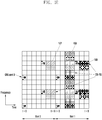
- FIGURE 1D illustrates a resource element mapping for PSS and SSS in a sub-frame for FDD according to this disclosure.
- the embodiment of the resource element mapping 190 shown in FIGURE 1D is for illustration only. Other embodiments could be used without departing from the scope of the present disclosure.
- the PSS and the SSS is mapped to the center 6 physical resource blocks (72 subcarriers) 191 in the system bandwidth 192 of the last OFDM symbol of the first slot 193 and the second last OFDM symbol of the first slot 194 of sub-frame #0 and sub-frame #5 195, respectively.
- the PSS and SSS only occupy 62 resource elements each, there are five unused resource elements 196 on each side of the PSS and the SSS.
- FIGURE 1E illustrates the resource element mapping for possible CSI-RS resources according to this disclosure.
- the embodiment of the resource element mapping shown in FIGURE 1E is for illustration only. Other embodiments could be used without departing from the scope of the present disclosure.
- the CSI-RS resources include NZP CSI-RS and ZP CSI-RS, that can be configured to the UE 116.
- a ZP CSI-RS resource is configured as a 4-port CSI-RS resource.
- One or more ZP CSI-RS resources can be configured to a UE through higher layer signaling, such as resources 197, 198, 199. For example, it is possible to configure all resource elements in the 3 rd OFDM symbol and the 4 th OFDM symbol of the second slot of a subframe to be ZP CSI-RS resources (up to six ZP CSI-RS resources can be configured in the 3 rd and the 4 th OFDM symbols of the second slot).
- a DCI for downlink assignment contains downlink scheduling information such as the rank of transmission and the Modulation and Coding Scheme (MCS) (5 bits) for each transport block that a UE shall assume for decoding the scheduled transport block.
- MCS Modulation and Coding Scheme
- the MCS indicated by an eNB for a transport block enables the UE 116 to determine the modulation order (one of QPSK, 16QAM and 64QAM) as well as the Transport Block Size (TBS), through a Modulation and TBS index table for PDSCH (Table 7.1.7.1-1 in REF 3) and one of the predefined transport block size tables depending on the number of spatial multiplexing layers (Table 7.1.7.2.1-1, Table 7.1.7.2.2-1, Table 7.1.7.2.4-1, Table 7.1.7.2.5-1 in REF 3).
- the eNB 103 can determine a rank of transmission and a MCS/TBS associated with a TB for a UE based on UE Channel State Information (CSI) measurement feedbacks, such as Rank Indicator (RI), Precoder Matrix Indicator (PMI) and Channel Quality Indicator (CQI).
- CSI Channel State Information
- RI Rank Indicator
- PMI Precoder Matrix Indicator
- CQI Channel Quality Indicator
- a CQI index is transmitted by the UE which indicates the recommended modulation order and code rate according to a 4-bit CQI table (Table 7.2.3-1 in REF 3).
- High order modulation 256 QAM is introduced for LTE for spectral efficiency enhancement.
- a PDSCH can be transmitted using 256QAM when the signal-to-noise-and-interference ratio is high (e.g. > 20dB).
- a new Modulation and TBS index table for PDSCH table that include entries corresponding to 256QAM is to be defined.
- the UE 116 uses the new table to interpret the MCS field in a DCI for PDSCH assignment.
- new TBS tables and a new CQI table include entries corresponding to 256QAM are to be defined to enable higher data rate.
- the UE 116 should not assume the new interpretation of MCS field in a DCI for all possible downlink assignment DCI formats.
- DCI formats that are used for the so-called “fallback” operation may not utilize the new table.
- “Fallback” operation allows an eNB to maintain communication with a UE regardless of the present transmission mode configuration at the UE.
- “Fallback” operation is also needed whenever there is an ambiguity about a UE's current RRC configurations which occurs naturally during a RRC reconfiguration process.
- Embodiments of the present disclosure define conditions that determine when the UE is and is not allowed to assume new interpretation of MCS field in a DCI. Embodiments of the present disclosure also define conditions that determine when the UE is and is not allowed to use the new CQI table for a CQI reporting.
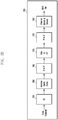
- FIGURES 2A and 2B illustrate example wireless transmit and receive paths according to this disclosure.
- a transmit path 200 may be described as being implemented in an eNB (such as eNB 102), while a receive path 250 may be described as being implemented in a UE (such as UE 116).
- the receive path 250 could be implemented in an eNB and that the transmit path 200 could be implemented in a UE.
- the transmit path 200 and receive path 250 are configured for measurement and discovery for LTE Advanced signals.
- the transmit path 200 includes a channel coding and modulation block 205, a serial-to-parallel (S-to-P) block 210, a size N Inverse Fast Fourier Transform (IFFT) block 215, a parallel-to-serial (P-to-S) block 220, an add cyclic prefix block 225, and an up-converter (UC) 230.
- S-to-P serial-to-parallel
- IFFT Inverse Fast Fourier Transform
- P-to-S parallel-to-serial
- UC up-converter
- the receive path 250 includes a down-converter (DC) 255, a remove cyclic prefix block 260, a serial-to-parallel (S-to-P) block 265, a size N Fast Fourier Transform (FFT) block 270, a parallel-to-serial (P-to-S) block 275, and a channel decoding and demodulation block 280.
- DC down-converter
- S-to-P serial-to-parallel
- FFT Fast Fourier Transform
- P-to-S parallel-to-serial
- the channel coding and modulation block 205 receives a set of information bits, applies coding (such as a low-density parity check (LDPC) coding or turbo coding), and modulates the input bits (such as with Quadrature Phase Shift Keying (QPSK) or Quadrature Amplitude Modulation (QAM)) to generate a sequence of frequency-domain modulation symbols.
- the serial-to-parallel block 210 converts (such as de-multiplexes) the serial modulated symbols to parallel data in order to generate N parallel symbol streams, where N is the IFFT/FFT size used in the eNB 102 and the UE 116.
- the size N IFFT block 215 performs an IFFT operation on the N parallel symbol streams to generate time-domain output signals.
- the parallel-to-serial block 220 converts (such as multiplexes) the parallel time-domain output symbols from the size N IFFT block 215 in order to generate a serial time-domain signal.
- the add cyclic prefix block 225 inserts a cyclic prefix to the time-domain signal.
- the up-converter 230 modulates (such as up-converts) the output of the add cyclic prefix block 225 to an RF frequency for transmission via a wireless channel.
- the signal may also be filtered at baseband before conversion to the RF frequency.
- a transmitted RF signal from the eNB 102 arrives at the UE 116 after passing through the wireless channel, and reverse operations to those at the eNB 102 are performed at the UE 116.
- the down-converter 255 down-converts the received signal to a baseband frequency
- the remove cyclic prefix block 260 removes the cyclic prefix to generate a serial time-domain baseband signal.
- the serial-to-parallel block 265 converts the time-domain baseband signal to parallel time domain signals.
- the size N FFT block 270 performs an FFT algorithm to generate N parallel frequency-domain signals.
- the parallel-to-serial block 275 converts the parallel frequency-domain signals to a sequence of modulated data symbols.
- the channel decoding and demodulation block 280 demodulates and decodes the modulated symbols to recover the original input data stream.
- Each of the eNBs 101-103 may implement a transmit path 200 that is analogous to transmitting in the downlink to UEs 111-116 and may implement a receive path 250 that is analogous to receiving in the uplink from UEs 111-116.
- each of UEs 111-116 may implement a transmit path 200 for transmitting in the uplink to eNBs 101-103 and may implement a receive path 250 for receiving in the downlink from eNBs 101-103.
- FIGURES 2A and 2B can be implemented using only hardware or using a combination of hardware and software/firmware.
- at least some of the components in FIGURES 2A and 2B may be implemented in software, while other components may be implemented by configurable hardware or a mixture of software and configurable hardware.
- the FFT block 270 and the IFFT block 215 may be implemented as configurable software algorithms, where the value of size N may be modified according to the implementation.
- variable N may be any integer number (such as 1, 2, 3, 4, or the like) for DFT and IDFT functions, while the value of the variable N may be any integer number that is a power of two (such as 1, 2, 4, 8, 16, or the like) for FFT and IFFT functions.
- FIGURES 2A and 2B illustrate examples of wireless transmit and receive paths
- various changes may be made to FIGURES 2A and 2B .
- various components in FIGURES 2A and 2B could be combined, further subdivided, or omitted and additional components could be added according to particular needs.
- FIGURES 2A and 2B are meant to illustrate examples of the types of transmit and receive paths that could be used in a wireless network. Any other suitable architectures could be used to support wireless communications in a wireless network.
- FIGURE 3 illustrates an example UE 116 according to this disclosure.
- the embodiment of the UE 116 illustrated in FIGURE 3 is for illustration only, and the UEs 111-115 of FIGURE 1 could have the same or similar configuration.
- UEs come in a wide variety of configurations, and FIGURE 3 does not limit the scope of this disclosure to any particular implementation of a UE.
- the UE 116 includes an antenna 305, a radio frequency (RF) transceiver 310, transmit (TX) processing circuitry 315, a microphone 320, and receive (RX) processing circuitry 325.
- the UE 116 also includes a speaker 330, a main processor 340, an input/output (I/O) interface (IF) 345, a keypad 350, a display 355, and a memory 360.
- the memory 360 includes a basic operating system (OS) program 361 and one or more applications 362.
- OS basic operating system
- the RF transceiver 310 receives, from the antenna 305, an incoming RF signal transmitted by an eNB of the network 100.
- the RF transceiver 310 down-converts the incoming RF signal to generate an intermediate frequency (IF) or baseband signal.
- the IF or baseband signal is sent to the RX processing circuitry 325, which generates a processed baseband signal by filtering, decoding, and/or digitizing the baseband or IF signal.
- the RX processing circuitry 325 transmits the processed baseband signal to the speaker 330 (such as for voice data) or to the main processor 340 for further processing (such as for web browsing data).
- the TX processing circuitry 315 receives analog or digital voice data from the microphone 320 or other outgoing baseband data (such as web data, e-mail, or interactive video game data) from the main processor 340.
- the TX processing circuitry 315 encodes, multiplexes, and/or digitizes the outgoing baseband data to generate a processed baseband or IF signal.
- the RF transceiver 310 receives the outgoing processed baseband or IF signal from the TX processing circuitry 315 and up-converts the baseband or IF signal to an RF signal that is transmitted via the antenna 305.
- the main processor 340 can include one or more processors or other processing devices and execute the basic OS program 361 stored in the memory 360 in order to control the overall operation of the UE 116.
- the main processor 340 could control the reception of forward channel signals and the transmission of reverse channel signals by the RF transceiver 310, the RX processing circuitry 325, and the TX processing circuitry 315 in accordance with well-known principles.
- the main processor 340 includes at least one microprocessor or microcontroller.
- the main processor 340 is also capable of executing other processes and programs resident in the memory 360, such as operations for measurement and discovery for LTE Advanced signals and performing low overhead synchronization for beam-formed systems.
- the main processor 340 can move data into or out of the memory 360 as required by an executing process.
- the main processor 340 is configured to execute the applications 362 based on the OS program 361 or in response to signals received from eNBs or an operator.
- the main processor 340 is also coupled to the I/O interface 345, which provides the UE 116 with the ability to connect to other devices such as laptop computers and handheld computers.
- the I/O interface 345 is the communication path between these accessories and the main controller 340.
- the main processor 340 is also coupled to the keypad 350 and the display unit 355.
- the operator of the UE 116 can use the keypad 350 to enter data into the UE 116.
- the display 355 may be a liquid crystal display or other display capable of rendering text and/or at least limited graphics, such as from web sites.
- the memory 360 is coupled to the main processor 340.
- Part of the memory 360 could include a random access memory (RAM), and another part of the memory 360 could include a Flash memory or other read-only memory (ROM).
- RAM random access memory
- ROM read-only memory
- FIGURE 3 illustrates one example of UE 116
- various changes may be made to FIGURE 3 .
- various components in FIGURE 3 could be combined, further subdivided, or omitted and additional components could be added according to particular needs.
- the main processor 340 could be divided into multiple processors, such as one or more central processing units (CPUs) and one or more graphics processing units (GPUs).
- FIGURE 3 illustrates the UE 116 configured as a mobile telephone or smartphone, UEs could be configured to operate as other types of mobile or stationary devices.
- CSI-RS is a physical signal measured by the UE to generate short term CSI.
- Examples of short term CSI include a Precoding Type Indicator (PTI), Rank Indicator (RI), Precoding Matrix Indicator (PMI) and Channel Quality Indicator (CQI).
- PTI Precoding Type Indicator
- RI Rank Indicator
- PMI Precoding Matrix Indicator
- CQI Channel Quality Indicator
- Short term CSI can be configured by the network when the UE is in Radio Resource Control (RRC) connected mode.
- RRC Radio Resource Control
- Configuration information for CSI-RS in LTE Rel-10 includes the number of antenna ports, the resource configuration (also called CSI RS configuration or CSI configuration, used to indicate resources within a sub-frame), the sub-frame configuration (used to indicate the sub-frames used for CSI-RS transmission by providing the periodicity and the sub-frame offset) and the parameter P c .
- Configuration for CSI-RS in LTE Rel-11 includes a CSI-RS identity, the number of antenna ports, the resource configuration, the sub-frame configuration, scrambling identity and information about CRS that is quasi co-located with the CSI-RS. (See REF 3 and REF 7).
- the RE mapping of CSI-RS is specified in REF 1 and is provided in Table 1 for the case of normal cyclic prefix, where (k',l') as defined in REF 1 represents the subcarrier index and the OFDM symbol index within a physical resource block (a block of 12 subcarriers and 0.5 ms (1 slot) duration).
- FIGURE 4A and 4B illustrate a mapping of CSI Reference Signals according to embodiments of this disclosure.
- the embodiment of the CSI Reference Signal mapping 400 shown in FIGURE 4A and 4B is for illustration only. Other embodiments could be used without departing from the scope of the present disclosure.
- the RE mapping of CSI-RS ports (labelled as port 15 to 22 in REF 1) for CSI-RS configuration 0 (i.e. resource configuration 0) is illustrated for the normal cyclic prefix.
- Certain embodiments provide new and enhanced discovery and detection methods in order to assist UE 116 to discover, or detect, and measure cells.
- the cells such as one or more of eNB 103 and FBS 160, to be detected by UE 116 are assumed to transmit signals that are then measured by UE 116.
- a candidate signal is the Channel State Information Reference Signal (CSI-RS).
- Other candidate signals are the Positioning Reference Signal (PRS), a modified PSS/SSS/CRS, or a newly designed physical signal, or a combination of the aforementioned signals.
- Cell or TP detection using discovery reference signal (DRS) includes the procedure of DRS measurement according to configuration by the network and reporting according to a predetermined or configured reporting criterion.
- transmission points also is used herein to denote “cells” that share the same Physical Cell Identity (PCI) for common signals transmissions but uses unique virtual cell id for unicast transmissions are deployed. Additional terms to which TP applies are: “cell identity”, “cell detection”, “cell measurement”, in which "cell” is replaced by “TP”, such as “TP identity”, “TP detection”, “TP measurement”.
- PCI Physical Cell Identity
- FIGURES 5 , 6 , 7 , 8 and 9 illustrate Discovery Reference Signal (DRS) occasions according to embodiments of this disclosure.
- DRS Discovery Reference Signal
- the embodiments of the DRS occasions shown in FIGURES 5 , 6 , 7 , 8 and 9 are for illustration only. Other embodiments could be used without departing from the scope of the present disclosure.
- the transmission point is eNB 103, however, the transmission point can be FBS 160 or another cell, such as a nano cell, femto cell and the like.
- N 1 for DRS occasion 500.
- N 2 for DRS occasion 600.
- the embodiments described with respect to FIGURES 5 through 9 are also referenced herein as Embodiment 1.
- UE 116 uses discovery signals 505 for cell or transmission point detection that includes one or more of: PSS, SSS, CRS and, if configured, CSI-RS.
- a discovery reference signal (DRS) occasion 500 of a cell or TP is defined as a set of consecutive DRS sub-frames (N sub-frames), transmitted periodically by eNB 103 or FBS 160, where each DRS sub-frame contains at least one of: PSS, SSS, CRS and, if configured, CSI-RS.
- the DRS occasion 500 for multiple cells or TP may or may not overlap in time. Aligning multiple DRS occasions in time especially for cells or TPs on the same frequency is beneficial from UE power saving perspective.
- DRS timing configuration can include indication of the start of a DRS occasion. If the first sub-frame of the DRS occasion always has PSS+SSS for FDD, and SSS for TDD, the DRS timing configuration can include indication of the sub-frame location of PSS+SSS for FDD, and SSS for TDD.
- the PSS, SSS, CRS, and CSI-RS are all transmitted in one sub-frame 510.
- DRS occasions of multiple cells or TPs on the same frequency can coincide in the same sub-frame or time multiplexed over at least two sub-frames 515.
- the sub-frames for DRS occasions of multiple cells/TPs can fit in a legacy measurement gap configuration.
- the DRS occasions of multiple cells or TPs in the same sub-frame can be configured (such as by RRC) for cell/TP identification and RRM measurement (CRS or CSI-RS based RSRP/RSRQ) with a DRS timing configuration.
- One DRS timing configuration may include information of only one starting sub-frame of a DRS occasion, in which case the UE 116 can be configured with multiple DRS timing configurations. In another option, one DRS timing configuration may also include information of more than one starting sub-frame of DRS occasions. For CoMP scenario 4 (or shared cell id deployment scenario), multiple CSI-RSs by the same cell (each CSI-RS corresponds to a TP) can exist.
- PSS and SSS 605 are in different sub-frames for TDD.
- the DRS timing configuration can indicate SF n and for TDD, the DRS occasions include SF n and SF n+1.
- the eNB 103 increases a number of measurement samples.
- the eNB 103 applies a transmission of a physical signal in multiple sub-frame of a DRS occasion to CSI-RS only, which is advantageous for improving the CSI-RS measurement accuracy (in the DRS occasion 705 in FIGURE 7 for FDD and in the DRS occasion 805 in FIGURE 8 for TDD).
- the eNB 103 transmits the CRS and, if configured, the CSI-RS, in multiple sub-frames of a DRS occasion, such as 5ms or 6ms of consecutive sub-frames (in the DRS occasion 710 in FIGURE 7 for FDD and in the DRS occasion 810 in FIGURE 8 for TDD).
- the eNB 103 : 1) transmits the CRS of the same cell/TP in multiple sub-frames of a DRS occasion; 2) but only transmits the CSI-RS of the same cell or TP in a subset of sub-frames, such as one sub-frame out of the DRS occasion sub-frames.
- the DRS timing configuration can also include the timing offset (ms or sub-frame) of the start of CSI-RS sub-frame relative to the starting sub-frame of the DRS occasion.
- a sub-frame is a special sub-frame for TDD
- eNB 103 does not transmit CSI-RS or the UE 116 assumes that eNB 103 does not transmit CSI-RS.
- the DRS timing configuration can indicate the first sub-frame of DRS occasions (i.e. SF n).
- DRS timing configuration can also include duration information or the number N.
- a DRS occasion can also consists of all sub-frames within the measurement gap 905 (as shown in FIGURE 9 ), in which case the measurement gap configuration can indicate the start of a DRS occasion.
- the first sub-frame of a DRS occasion can carry the PSS and the SSS.
- the first sub-frame of a DRS occasion can carry the SSS and the second sub-frame of a DRS occasion can carry the PSS. This is advantageous to enable the UE 116 to perform synchronization with the PSS/SSS first before receiving CRS and/or CSI-RS.
- multiple CSI-RSs by the same cell can exist.
- sub-frame n can either be sub-frame 0 or sub-frame 5, such that the location of PSS or SSS indicates the possible sub-frame index of the cell or TP detected.
- SF n+1 is a special sub-frame.
- SF n+1 can also be the DL sub-frame for certain TDD configurations such as configuration 3, 4, and 5, hence CSI-RS can be transmitted in SF n+1 as well.
- UE assumes that CSI-RS is not present in the sub-frame or in the resource blocks where PBCH may be present.
- UE 116 determines (or assumes) that CSI-RS is present as in other sub-frames and the PBCH is determined (or assumed) to not be present.
- the network explicitly indicates a presence of CSI-RS in SF n , by higher layer signaling, such as RRC.
- UE 116 When the absence of CSI-RS is indicated for SF n , then UE 116 skips SF n when receiving CSI-RS. Alternatively, when the absence of CSI-RS is indicated for SF n , UE 116 also receives CSI-RS in SF n .
- eNB 103 when a DRS occasion contains multiple sub-frames with CSI-RS, eNB 103 enables configuration of multiple (consecutive) Zero-Power CSI-RS sub-frames with a single ZP-CSI-RS resource or configuration. In this way, when a eNB 103 configures this new ZP-CSI-RS configuration according to the CSI-RS patterns of DRS of its neighboring cells or TPs, the CSI-RS of DRS of neighboring cells/TPs is protected from interference of eNB 103, the configuring cell/TP.
- the UE 116 configured with this new ZP-CSI-RS configuration, is configure to assume that the corresponding ZP-CSI-RS REs are not used for data transmission and can be skipped when performing rate matching operation.
- the maximum number of ZP CSI-RS configurations that can be configured to a UE can be kept the same at 4 (as specified in Rel-11 LTE).
- the new ZP-CSI-RS configuration can be realized by introducing a new RRC information element (IE) to the existing ZP-CSI-RS configuration IE (CSI-RS-ConfigZP-r11).
- the new RRC ID is configured to indicate a duration or length of the ZP-CSI-RS sub-frames (e.g. 1 ms or 2ms or 5ms).
- the maximum number of ZP CSI-RS configurations that can be configured to a UE can be increased from 4 (as specified in Rel-11 LTE) to a larger number, such as, 20.
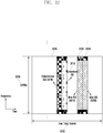
- FIGURE 10 illustrates an enhanced CSI-RS with 4 resource elements per physical resource block pair according to embodiments of the present disclosure.
- the embodiments of the enhanced CSI-RS structures 1000, 1005 shown in FIGURE 10 are for illustration only. Other embodiments could be used without departing from the scope of the present disclosure.
- the CSI-RS (for example, the CSI-RS of the DRS occasion) is assumed as the signal used for cell detection, transmit point (TP) detection, or a combination of cell and TP detection, for descriptions of the embodiments of the present disclosure, unless stated otherwise. It is noted that the principles of the embodiments of the present disclosure are applicable also to other type of signals used for cell detection, including the CRS of DRS occasion and any enhanced CSI-RS design, such as as described in REF 10, where the density of the CSI-RS is proposed to be increased in the frequency domain to 4 REs per PRB-pair (resembling 4-port mapping) or 8 REs per PRB-pair (resembling 8-port mapping) as shown in FIGURE 10 .
- the periodicity of the enhanced CSI-RS transmission is modified to have lower duty cycle T 1105 so as to minimize network and UE power consumption as shown in FIGURE 11 .
- the enhanced CSI-RS design with higher frequency density, as described in REF 10 improves a detection performance due to a larger number of samples.
- using the enhanced CSI-RS also minimizes a performance impact to the legacy UEs since the enhanced CSI-RS resources can be configured as zero power CSI-RS resources. Additional methods to enhance CSI-RS for the purpose of cell detection and discovery are described in herein below with respect to FIGURE 17 .
- description of the discovery signal with reference to the CSI-RS does not necessarily imply that a respective structure will be same as for a conventional CSI-RS.
- an enhanced CSI-RS structure 1000, 1005 can be used.
- the network can configure UE 116 to detect and measure CSI-RSs from multiple cells that include neighboring cells, such as small cells, eNB 102 and eNB 101, and optionally, one or more serving cells, such as FBS 160 or eNB 103, to generate a signal quality measurement such as RSRP and/or Reference Signal Received Quality (RSRQ) and/or SINR of each cell.
- the cells to be detected and measured by the UE 116 can be from a same cluster of small cells or can be from multiple clusters of small cells.
- the UE 116 reports measurement results to the network when a reporting criterion is met. For example, UE 116 can be triggered to transmit a measurement reporting when a RSRP value is greater than a threshold.
- the threshold is configured by the network. In certain embodiments, the threshold is pre-configured. In certain embodiments, when the UE 116 does not have a PUSCH transmission, UE 116 transmits a service request, in a PUCCH, requesting a scheduling from a network for a PUSCH transmission in order to report measurement results for discovery signals. In certain embodiments, the UE 116 is configured by the network with a PUCCH resource or a PUSCH resource to use for reporting measurement results of discovery signals. The PUCCH or PUSCH resource is valid only for a sub-frame occurring after sub-frame(s) of transmissions of discovery signals and, therefore, an associated overhead for reporting measurement results is low.
- Embodiments of the present disclosure specify CSI-RS resource configuration method for cell detection purpose. Embodiments of the present disclosure also enable UE 116 to determine the identity of a cell transmitting a CSI-RS the UE detects. In certain embodiments, the UE 116 includes the identity of the cell in the measurement report so that the network is able to associate the measurement report with the corresponding cell identity. When the UE 116 detects multiple cells, the UE 116 reports a predetermined maximum number of the detected cells. The report from UE 116 can always include measurements for the predetermined maximum number of cells or a header can inform the network of the number of reported cells.
- the network configures the UE 116 to detect and measure multiple CSI-RS resources.
- the network can configure the UE 116 by higher layer signaling such as RRC signaling or MAC signaling.
- Each CSI-RS resource configuration consists of an identity of a CSI-RS resource, a resource configuration, a sub-frame configuration and a scrambling identity (used for generating a scrambling sequence for the CSI-RS).
- the UE 116 is configured to assume that a number of CSI-RS ports is one. In certain embodiments, a number of CSI-RS ports are also signaled to the UE 116.
- the network can also signal an index ([0, 1]) of a length-2 Orthogonal Cover Code (OCC).
- OCC Orthogonal Cover Code
- the UE 116 blindly detects an index for an OCC applied to a CSI-RS. In either case, the UE 116 is configured to recognize a cell with a single CSI-RS port that is spread with an OCC [1 -1] over consecutive symbols.
- the UE 116 is configured to assume that no OCC is applied or assumes a fixed OCC is applied, such as [1 1].
- csi-RS-ConfigNZPld-rxy represents the identity of the CSI-RS resource
- resourceConfig-rxy represents the resource configuration (also called CSI RS configuration or CSI configuration)
- sub-frameConfig-rxy represents the sub-frame configuration
- scramblingldentity-rxy represents the scrambling identity (may also be called the physical cell identity (PCID), virtual cell id (VCID), cell id (CID)):
- a list of CSI-RS resources is configured for detection of multiple CSI-RSs or cells, as illustrated by an example ASN.1 code below, by configuring the UE 116 with csi-RS-ConfigNZPToAddModList-rxy.
- csi-RS-ConfigNZPToAddModList-rxyCSI-RS-ConfigNZPToAddModList-rxyOPTIONAL,-- Need CSI-RS-ConfigNZPToAddModList-rxy :: SEQUENCE (SIZE (1..maxCSI-RS-NZP-rxy)) OF CSI-RS-ConfigNZP-rxy
- the discovery signals of multiple cells are transmitted in a same sub-frame or same set of OFDM symbols so as to minimize the wake up time for the UE 116 to detect the discovery signals, which in turn saves UE power consumption. Therefore, it can be typical that the same sub-frame configuration is applied for the CSI-RS resources of multiple cells.
- the sub-frame configuration for a group of cells with a same configuration is signalled only once, while the other configuration fields are signalled per CSI-RS resource, for example, as shown in an example ASN.1 code below, where CSI-RS-CommonConfigNZP-rxy is the container for common configuration (in this case, sub-frameConfig-rxy) of multiple CSI-RS resources and CSI-RS-ConfigNZPList-rxy specifies a list of CSI-RS resources where the common configuration is applicable. If the common configuration is always applicable for all CSI-RS resources configured, the indication of a list may not be needed.
- the scrambling identity is included as part of the common signalling.
- the UE 116 uses the indicated scrambling identity to detect the set CSI-RS resources configured.
- Common scrambling identity reduces CSI-RS detection complexity and improves detection performance.
- An example ASN.1 code is given below.
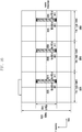
- FIGURE 12 illustrates different sub-frame configurations for different groups of small cells according to this disclosure.
- the embodiment of the sub-frame configurations 1200 shown in FIGURE 12 is for illustration only. Other embodiments could be used without departing from the scope of the present disclosure.
- the UE 116 may need to detect cells that do not share a same CSI-RS common configuration.
- different sub-frame configurations can be configured for different groups or clusters of small cells as shown in FIGURE 12 .
- a first CSI-RS transmission 1205 can be configured for a first group of cells while a second CSI-RS transmission 1210 is configured for a second group of cells.
- the UE 116 can be configured with multiple CSI-RS common configurations, each being applied to a separate set of CSI-RS resources.
- Method 2 the network configures a sub-frame configuration for CSI-RS(s) to be detected by the UE 116 but not their resource configurations or OCC indices.
- Method 2 A difference with respect to Method 1 is that the UE 116 is not informed which REs of the CSI-RS sub-frames (determined by resource configuration) contain CSI-RS. The UE 116 is required to try to detect the presence of a CSI-RS in the CSI-RS sub-frames determined by the sub-frame configuration.
- 40 possible CSI-RS resources can exist in a sub-frame for normal CP that the UE 116 needs to try to detect (each cell's CSI-RS occupies one CSI-RS port, there are 20 unique time-frequency RE-pair locations and 2 time-domain orthogonal cover code for each time-frequency RE-pair).
- 20 possible CSI-RS resources exist in a sub-frame for normal CP that the UE 116 needs to try to detect (each cell's CSI-RS occupies one CSI-RS port, there are 20 unique time-frequency RE-pair locations and only one time-domain orthogonal cover code is used for each time-frequency RE-pair, such as [1 1]).
- all the CSI-RS resources corresponding to the sub-frame configuration can have the same scrambling identity for sequence generation.
- the scrambling identity can also be provided as shown in the example ASN.1 code below. Scrambling identity can be seen as a group-common scrambling identity.
- all the CSI-RS resources corresponding to the sub-frame configuration can have different scrambling identities.
- the scrambling identity is not provided as shown in the example ASN.1 code below.
- the CSI-RS detection configuration can also include a CSI-RS group identity (csi-RS-GroupConfigNZPld-rxy).
- a CSI-RS group can consist of a group of CSI-RS resources to be detected by the UE 116.
- a CSI-RS group can correspond to the CSI-RS transmitted by small cells in the same cluster as shown in FIGURE 12 .
- the CSI-RS transmitted by small cells in the same cluster can correspond to the first CSI-RS transmission 1205 for the first group of cells.
- the CSI-RS transmitted by small cells in the same cluster can correspond to the second CSI-RS transmission 1210 for the second group of cells.
- Each CSI-RS group can be associated with or configured with a set of PCIs of which the corresponding PSS/SSS can be assumed by the UE 116 for coarse time and frequency synchronization (as illustrated in Embodiment 2 herein below).
- the coordination among cells regarding the CSI-RS transmission have the advantage of only needing to involve the sub-frames used for CSI-RS transmissions, but not the actual RE locations of the CSI-RS; therefore eNB 103 is free to reconfigure a resource configuration of its own CSI-RS without informing other eNodeBs, such as eNB 101 or eNB 102.
- the network also can signal multiple CSI-RS sub-frame configurations, such as by signaling a list of CSI-RS configurations, if the number of CSI-RS resources to be searched exceeds the maximum number of CSI-RS resources for a sub-frame configuration.
- the possible CSI-RS resources defined by the CSI-RS sub-frame configuration constitute the CSI-RS search space.
- the neighboring eNodeBs such as eNB 101 and eNB 102, can exchange information on the respective CSI-RS configurations so that each eNodeB can configure to their respective UEs the appropriate CSI-RS configurations.
- a large CSI-RS search space increases UE signal processing time.
- the large CSI-RS search space also increases false alarm probability.
- the network signals a reduced set of resources to be searched by UE 116.
- the network can indicate to the UE 116 that a total number of CSI-RS resources to be searched is 20 and the UE 116 only searches in the first 20 CSI-RS resource locations.
- the network additionally signals a starting position for CSI-RS resources to be searched.
- embodiments of the present disclosure define an ordering/labeling of CSI-RS resources (CSI-RS resource indexing) so that UE 116 is able to understand the signaling by the network.
- the ordered CSI-RS resources are labeled with an index, called CSI-RS index.
- This mapping of CSI-RS index and physical resource is represented in Table 2. This ordering or mapping method minimizes the use of code-division multiplexing for CSI-RS resources, which helps to improve detection robustness for CSI-RS resources detection considering a time or a frequency offset.
- CSI-RS index 1 - 20 are applicable.
- CSI-RS index Frequency and time location OCC[W 0 W 1 ] (k',l') n s mod 2 1 (2,5) 0 [1 1] 2 (3,5) 0 [1 1] 3 (8,5) 0 [1 1] 4 (9,5) 0 [1 1] 5 (0,2) 1 [1 1] 6 (1,2) 1 [1 1] 7 (2,2) 1 [1 1] 8 (3,2) 1 [1 1] 9 (4,2) 1 [1 1] 10 (5,2) 1 [1 1] 11 (6,2) 1 [1 1] 12 (7,2) 1 [1 1] 13 (8,2) 1 [1 1] 14 (9,2) 1 [1 1] 15 (10,2) 1 [1 1] 16 (11,2) 1 [1 1] 17 (2,5) 1 [1 1] 18 (3,5) 1 [1 1] 19 (8,5) 1 [1 1] 20 (9,5) 1 [1 1] 21 (2,5) 0 [1 -1] 22 (3,5) 0 [1 -1] 23 (8,5) 0 [1 -1] 20
- CSI-RS index Frequency and time location OCC[w 0 w 1 ] (k',l') n s mod 2 1 (0,2) 1 [1 1] 2 (1,2) 1 [1 1] 3 (2,2) 1 [1 1] 4 (3,2) 1 [1 1] 5 (4,2) 1 [1 1] 6 (5,2) 1 [1 1] 7 (6,2) 1 [1 1] 8 (7,2) 1 [1 1] 9 (8,2) 1 [1 1] 10 (9,2) 1 [1 1] 11 (10,2) 1 [1 1] 12 (11,2) 1 [1 1] 13 (2,5) 0 [1 1] 14 (3,5) 0 [1 1] 15 (8,5) 0 [1 1] 16 (9,5) 0 [1 1] 17 (2,5) 1 [1 1] 18 (3,5) 1 [1 1] 19 (8,5) 1 [1 1] 20 (9,5) 1 [1 1] 21 (0,2) 1 [1 -1] 22 (1,2) 1 [1 -1] 23 (2,2) 1 [1 -1] 24
- the ordering is represented in Table 4.
- CSI-RS index Frequency and time location OCC[w 0 w 1 ] (k',l') n s mod 2 1 (2,5) 0 [1 1] '2 (2,5) 0 [1 -1] 3 (3,5) 0 [1 1] 4 (3,5) 0 [1 -1] 5 (8,5) 0 [1 1] 6 (8,5) 0 [1 -1] 7 (9,5) 0 [1 1] 8 (9,5) 0 [1 -1] 9 (0,2) 1 [1 1] 10 (0,2) 1 [1 -1] 11 (1,2) 1 [1 1] 12 (1,2) 1 [1 -1] 13 (2,2) 1 [1 1] 14 (2,2) 1 [1 -1] 15 (3,2) 1 [1 1] 16 (3,2) 1 [1 -1] 17 (4,2) 1 [1 1] 18 (4,2) 1 [1 -1] 19 (5,2) 1 [1 1] 20 (5,2) 1 [1 -1] 21 (6,2) 1 [1 1] 22 (6,2) 1 [1 [1]
- CSI-RS index Frequency and time location OCC[w 0 w 1 ] (k',l') n s mod 2 1 (2,5) 0 [1 1] 2 (2,5) 0 [1 -1] 3 (3,5) 0 [1 1] 4 (3,5) 0 [1 -1] 5 (8,5) 0 [1 1] 6 (8,5) 0 [1 -1] 7 (9,5) 0 [1 1] 8 (9,5) 0 [1 -1] 9 (0,2) 1 [1 1] 10 (0,2) 1 [1 -1] 11 (1,2) 1 [1 1] 12 (1,2) 1 [1 -1] 13 (2,2) 1 [1 1] 14 (2,2) 1 [1 -1] 15 (3,2) 1 [1 1] 16 (3,2) 1 [1 -1] 17 (4,2) 1 [1 1] 18 (4,2) 1 [1 -1] 19 (5,2) 1 [1 1] 20 (5,2) 1 [1 -1] 21 (6,2) 1 [1 1] 22 (6,2) 1 [1 -1] 19
- the principles described here can easily extend to other CSI-RS resource mapping defined in LTE Rel-10/11 (that is, mapping for extended CP and for other TDD mapping). It is also noted that the methods described here can easily extend to mapping of CSI-RS resources of multiple sub-frame configurations to CSI-RS indices, that is, the CSI-RS index is unique for CSI-RS resources from multiple sub-frame configurations.
- the CSI-RS index mapping can be applied for a DRS timing configuration which is associated with a group of DRS occasions or a group of CSI-RS resources.
- the network signals, such as via higher layer signaling, piece-wise ranges of CSI-RS resource positions to be searched by the UE 116.
- a CSI-RS resource ordering in a sub-frame can be as previously described.
- the network can signal that CSI-RS resources are from 1 to 5 and from 10 to 20 (assuming the first CSI-RS resource is labeled as 1).
- N ID CSI which is the same as the scrambling identity of the CSI-RS as defined in TS 36.331 V11.3.0, takes a value from 0 to 503 (or the scramblingldentity-rxy above).
- the UE 116 tries to detect a presence of CSI-RS with N lD CSI from 0 to 503 (with non-coherent detection techniques) or with a single indicated N ID CSI value.
- the network reduces the possible N lD CSI to be searched by the UE 116.
- a range of N ID CSI can be signaled, such as by higher layer signaling, given by a starting value and a range value.
- the UE 116 is signaled by higher layers an explicit set of N ID CSI values.
- Certain embodiments illustrate a relationship between the CSI-RS index and N D CSI .
- the UE 116 is either signaled separately a set CSI-RS indices and a set of N ID CSI to be searched or the UE 116 is configured to assume a valid range for each parameter without signaling.
- the UE 116 also can be signaled a mapping between a CSI-RS index and a N lD CSI to a PCI (see Table 6 & Table 7 for two examples), such as via RRC signaling or via a predefined mapping table (cell identification table). Mapping of multiple CSI-RS resources to a PCI is also possible for certain deployment scenarios (such as, CoMP scenario 4 as described in REF 11) (see also Table 8).
- the sub-frame configuration also is included in the mapping to PCI as illustrated in Table 11 (Table 9 and Table 10 illustrate when a mapping of multiple CSI-RS resources to a PCI is possible.)
- the UE 116 also can be signaled a set of PCIs and the UE 116 is configured to determine the set of CSI-RS resources to be detected.
- the UE 116 detects a CSI-RS resource, the UE 116 is configured to determine the PCI detected, that is, the mapping of CSI-RS resource to PCI allows cell identification.
- CSI-RS resource N ID CSI CSI-RS index PCI Resource 1 Scrambling id 1 1 PCI 1 Resource 2 Scrambling id 1 2 PCI 2 Resource 3 Scrambling id 1 3 PCI 3 Resource 4 Scrambling id 2 4 PCI 4 Resource 5 Scrambling id 2 5 PCI 5 Resource 6 Scrambling id 2 6 PCI 6 Mapping between a CSI-RS index and a N ID CSI to a PCI
- CSI-RS resource N ID CSI CSI-RS index PCI Resource 1 Scrambling id 1 1 PCI 1 Resource 2 Scrambling id 2 2 PCI 2 Resource 3 Scrambling id 3 3 PCI 3 Resource 4 Scrambling id 4 4 PCI 4 Resource 5 Scrambling id 5 5 PCI 5 Resource 6 Scrambling id
- Quasi co-location of PSS/SSS/CRS/DM-RS ports associated with PCI and CSI-RS ports also can be defined using the mapping tables.
- a CSI-RS resource 1 that is mapped to a PCI 1 means that PSS/SSS/CRS/DM-RS associated with PCI 1 can be assumed by the UE 116 to be quasi co-located with CSI-RS resource 1 in terms of delay spread, Doppler spread, Doppler shift, average gain, and average delay.
- a CSI-RS resource 1 that is mapped to a PCI 1 means that PSS/SSS/CRS/DM-RS associated with PCI 1 can be assumed by the UE 116 to be quasi co-located with CSI-RS resource 1 in terms of Doppler shift and average delay. Further signaling support can be provided if there is a need to address deployment scenarios such as CoMP scenario 4.
- Quasi-co-location (QCL) type signaling can be provided to indicate if the QCL linkage between a CSI-RS resource and PSS/SSS/CRS/DM-RS associated with a PCI is based on a first type (Type 1) or a second type (Type 2) (see Table 10). For example:
- the QCL linkage can improve reception performance of CSI-RS resource by exploiting the QCL relationship with detected PSS/SSS/CRS/DM-RS and vice versa.
- the CSI-RS resource can include RSRP measurement based on CSI-RS.
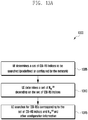
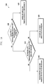
- FIGURE 13A illustrates a process 1300 to determine as set of values to be searched from a set of CSI-RS indices according to this disclosure.
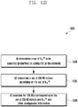
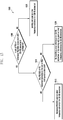
- FIGURE 13B illustrates a process 1305 to determine a set of CSI-RS indices to be searched from a set of values according to this disclosure. While the flow charts depict a series of sequential steps, unless explicitly stated, no inference should be drawn from that sequence regarding specific order of performance, performance of steps or portions thereof serially rather than concurrently or in an overlapping manner, or performance of the steps depicted exclusively without the occurrence of intervening or intermediate steps.
- the processes depicted in the examples depicted are implemented by a transmitter chain in, for example, a mobile station or a base station.
- relation/mapping between CSI-RS index and N lD CSI is defined to save signaling overhead such that the UE 116 is able to determine a set of CSI-RS indices to be searched from the signaling of a set of N ID CSI and vice versa as shown in FIGURES 13A and 13B .
- the CSI-RS index is determined from N ID CSI of the corresponding CSI-RS.
- the network can either signal a range or a set of N ID CSI values to be detected by a UE 116, as well as the sub-frame configuration.
- the UE 116 is configured to determine a set of CSI-RS resources in the corresponding sub-frames for detection and measurement.
- the network signals a range or a set of CSI-RS indices to be detected by the UE 116 as well as the sub-frame configuration.
- the UE 116 also is configured to determine the scrambling identities (e.g., N lD CSI ) to attempt CSI-RS detection for a given CSI-RS index in block 1325. Extension of this method to map CSI-RS index defined uniquely over multiple sub-frame configurations to N lD CSI in block 1330. The mapping of CSI-RS index over multiple sub-frame configurations to N ID CSI is straightforward.
- This method has an advantage of reducing the CSI-RS searching complexity for the UE 116 in block 1335, improving detection performance by reducing the number of candidates as well as reducing signaling over X2 or between the eNB 103 and the UE 116.
- N is less than the number of possible values for N ID CSI
- the UE 116 can blindly detect N ID CSI of the CSI-RS corresponding to the CSI-RS index in block 1315.
- the resource elements configured, or potentially configured, for CSI-RS transmission are configured by the network to be zero-power CSI-RS resources for UEs, such that UE 116 does not assume an existence of other useful physical signals in the corresponding resource elements.
- Symbols for physical channels, such as PDSCH and EPDCCH, are not mapped onto the configured zero-power CSI-RS resources.
- configuration messages are delivered in a UE-dedicated RRC signaling.
- configuration messages are delivered in a broadcast channel (as part of an existing or new System Information Block).
- Certain embodiments provide, for all methods of CSI-RS detection configuration, support for on-demand measurement report request to allow the network the flexibility to obtain an up-to-date measurement report in a timely manner, such as for deciding if a cell that has been in dormant state, but is still transmitting the discovery signal, should be turned on or not.
- the UE 116 can be signaled a request to prepare for an on-demand measurement report via paging or dynamic control channel (PDCCH/EPDCCH).
- a discovery signal is expected by the UE 116 to be transmitted in a predetermined later time (such as 10ms after the reception of the request).
- the timing of the discovery transmission upon reception of a request can either be predefined (fixed) or can be configurable by the network.
- the UE 116 is configured to attempt to detect and measure the discovery signals at the time determined and report its measurement results and the identities of the discovery signals detected.
- configuration messages are also included in a handover command. Therefore, the UE 116 is able to perform CSI-RS detection as soon as possible during or after a handover procedure.
- Certain embodiments for all methods of CSI-RS or TP detection configuration, define how an identity of a CSI-RS resource or TP is defined in a measurement report.
- an identity of a CSI-RS resource (which allows the network to identify uniquely the cell detected) to be included in the measurement report can be different.
- the UE 116 reports the CSI-RS resource configuration, the scrambling identity and OCC index, together with the measurement result (e.g. RSRP/RSRQ), in a measurement report for the detected CSI-RS.
- the measurement result e.g. RSRP/RSRQ
- the UE 116 reports the CSI-RS index and the corresponding measurement results.
- the measurement results can be, for example, the RSRP/RSRQ.
- the UE 116 reports the scrambling identity and the corresponding measurement results, such as RSRP/RSRQ.
- the scrambling identities can be reused in different group of CSI-RS resources (representing different small cell cluster or a different group of transmission points in CoMP scenario 4) (that is, a CSI-RS scrambling identity is only unique within a CSI-RS group)
- the PCI of the PSS/SSS used as coarse time and frequency synchronization for the CSI-RS detection also is reported.
- the CSI-RS group index can be reported.
- the sub-frame configuration of the detected CSI-RS can be reported.
- the CSI-RS resource is uniquely identified by a combination of its CSI-RS index and its scrambling identity.
- the UE 116 reports the CSI-RS index as well as the scrambling identity and the corresponding measurement results, such as RSRP/RSRQ. If a mapping between a combination of a CSI-RS index and a scrambling identity to a PCI is commonly known at the eNB 103 and the UE 116, via RRC signaling or via a predetermined mapping table (Table 6), then the UE 116 can just report the PCI and the corresponding measurement results, such as RSRP/RSRQ.
- the CSI-RS resource is uniquely identified by a combination of its CSI-RS index, its scrambling identity and its sub-frame configuration.
- the UE 116 reports the CSI-RS index, the scrambling identity, the sub-frame configuration and the corresponding measurement results, such as RSRP/RSRQ.
- a mapping between a combination of a CSI-RS index, a scrambling identity and sub-frame configuration to a PCI is commonly known at the eNB 103 and the UE 116, via RRC signaling or via a predetermined mapping table (Table 11), then the UE 116 is configured to report the PCI and the corresponding measurement results, such as RSRP/RSRQ.
- the measurement report can include, for example, CSI-RS-CommonConfigNZPld-rxy of Method 1 or CSI-RS-GroupConfigNZPld-rxy of Method 2, as described above.
- the UE 116 when mapping of a CSI-RS resource identity and PCI is provided, via RRC signaling or via a predetermined mapping table, the UE 116 is configured to just report the PCI and the corresponding measurement results, such as RSRP/RSRQ, when the mapping is one-to-one. Otherwise, the UE 116 is configured to report additional information pertaining to the CSI-RS resource, which also needs to be reported. That is, the UE 116 can report the CSI-RS index, a CSI-RS scrambling id, a virtual id, or a combination thereof.
- a CSI-RS resource id or a TP id can be uniquely assigned to each CSI-RS resource or TP, as shown in the first column of Table 6, Table 7, Table 8, Table 9, Table 10 and Table 11.
- the UE 116 is configured to just report CSI-RS resource id or TP id and the corresponding measurement results, such as RSRP/RSRQ.
- Embodiment 2 Time and frequency reference for CSI-RS: when significant time and/or frequency offsets are present at a receiver in UE 116 when receiving a signal, the receiver performance will be degraded if the offsets are not compensated.
- a network it may not be possible for a network to ensure that CSI-RS detectable by the UE 116 are synchronized sufficiently in time (such as ⁇ 3 ⁇ s) and/or frequency (such as ⁇ 0.1 ppm) with respect to the serving cell in order to meet the minimum performance requirement for detection and measurement.
- a group of cells interconnected with high capability backhaul such as a fiber optic connection or the like, can be sufficiently synchronized to a reference cell, which may not be the serving cell of the UE 116. Therefore, in order to facilitate accurate detection and measurement performance by the UE 116, embodiments of the present disclosure provide a reference cell for synchronization for either time or frequency or both time and frequency, that the UE 116 is configured to assume when measuring a CSI-RS signal. In one option, the UE 116 is configured to assume that a target cell and its reference cell are synchronized to an extent to provide sufficiently accurate RRM measurement. For example, a timing difference is within ⁇ 3 ⁇ s and frequency difference is within ⁇ 0.1 ppm.
- the synchronization of the target cell and its reference cell may not be enough to meet the minimum performance requirement for data demodulation or the signals from the target cell and its reference cell may not be assumed to quasi co-located in terms of some large scale channel properties, which includes one or more of delay spread, Doppler spread, Doppler shift, average gain, and average delay.
- the UE 116 is configured to assume that the signals from the target cell and its reference cell are only quasi co-located in terms of Doppler shift and average delay.
- the UE 116 is configured to assume that the target cell and its reference cell are synchronized to an extent that can meet the minimum performance requirement for data demodulation.
- the UE 116 is configured to assume that the signals from the target cell and its reference cell are quasi co-located in terms of some large scale channel properties, which includes one or more of delay spread, Doppler spread, Doppler shift, average gain, and average delay.
- the UE may only reliably detects few small cells using PSS/SSS/CRS.
- a small cell such as FBS 160, that cannot be easily detected by the UE 116, transmits CSI-RS to facilitate detection by the UE 116.
- small cells in a cluster can be sufficiently synchronized in time and/or frequency. Therefore, UE 116 is configured to use one or multiple PSS/SSS/CRSs detected from any small cells in the cluster as the reference for detecting a CSI-RS of a small cells that otherwise cannot be detected by the UE 116 through only PSS/SSS/CRS.
- the UE 116 uses the strongest PSS/SSS/CRS signals as the reference or combines the reference signals detected to derive the reference time/frequency. As such, in certain embodiments for the cell discovery procedure, UE 116 is configured to assume multiple signals are transmitted, where a first signal or signals is the PSS/SSS/CRS, and the second signal is the CSI-RS (or other physical signals that can replace CSI-RS).
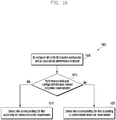
- FIGURE 14 illustrates a UE process 1400 for determining a reference time or reference frequency for CSI-RS detection according to embodiments of the present disclosure. While the flow chart depicts a series of sequential steps, unless explicitly stated, no inference should be drawn from that sequence regarding specific order of performance, performance of steps or portions thereof serially rather than concurrently or in an overlapping manner, or performance of the steps depicted exclusively without the occurrence of intervening or intermediate steps.
- the process depicted in the example depicted is implemented by a receiver chain or processing circuitry in, for example, a mobile station.
- the network provides a physical cell identity or a set of physical cell identities of the reference PSS/SSS for each or for a set of CSI-RS resources to be detected by UE 116.
- the set of CSI-RS resources to be searched by a UE can be as described herein above in Embodiment 1, with respect to FIGURES 5 through 9 .
- the PCIs of the reference PSS/SSS/CRS can be the same as the PCIs associated with the CSI-RS resources to be searched, such as illustrated in Table 6.
- the PCI of the reference PSS/SSS/CRS for each CSI-RS resource can be the same as the PCI associated with the CSI-RS resource such as illustrated in Table 6, Table 7, Table 8, Table 9, Table 10 and Table 11.
- the set of PCIs of the reference PSS/SSS/CRS for each CSI-RS resource can be the same as all or a subset of PCIs included in the mapping table such as illustrated in Table 7, Table 8, Table 9, Table 10 and Table 11, which can be advantageous if all CSI-RS resources are from the same cell cluster and hence are approximately synchronized (for example, the reference PSS/SSS/CRS and the corresponding CSI-RS are quasi co-located in terms of average delay and Doppler shift).
- the PCIs of the reference PSS/SSS/CRS for a cell can be the same as the PCIs associated with CSI-RS resources belonging to the same sub-frame configuration.
- PCI 1 - 6 are the references for any CSI-RS resource 1-6 and PCI 7-12 are the references for any CSI-RS resource 7-12.
- the PCIs of reference PSS/SSS/CRS also can be explicitly signaled by the network, such as via RRC, as shown in Table 12, where each CSI-RS resource has a set of reference PCIs.
- Table 13 Another example is illustrated in which the RRC signaling indicates the mapping of a set of CSI-RS resources to a set of reference PCIs.
- Table 14 is illustrated in which the RRC signaling indicates the mapping of a set of CSI-RS resources to a single reference PCI.
- Table 14 can be suitable for deployment scenarios where multiple transmission points are associated with the same PCI (such as CoMP scenario 4).
- Table 12 CSI-RS resource Reference PCIs 1 1 - 6 2 1 - 6 3 1 - 6 4 1 - 6 5 1 - 6 6 1 - 6 7 7 -12 8 7 -12 9 7 -12 10 7 -12 11 7 -12 12 7 -12 Reference PCIs signaling
- Table 13 CSI-RS resource Reference PCIs 1-6 1 - 6 7-12 7 -12 Reference PCIs signaling
- Table 14 CSI-RS resource Reference PCIs 1-6 1 7-12 2 Reference PCIs signaling
- the UE 116 is configured with a set of PCIs of reference PSS/SSS/CRSs associated with CSI-RS resource.
- the UE 116 Upon receiving the signaling of the reference PSS/SSS/CRS PCIs for a CSI-RS resource in block 1405, the UE 116 is configured to assume a same time and/or frequency reference for receiving a corresponding CSI-RS based on PSS/SSS/CRSs detected with a same PCI (for example, the reference PSS/SSS/CRS and the corresponding CSI-RS are quasi co-located in terms of average delay and Doppler shift).
- the UE 116 can use the strongest PSS/SSS/CRS signals as the reference or combine the reference signals detected to derive the reference time/frequency in block 1415. For example, UE 116 can use PSS/SSS detected for coarse time synchronization, and use CRS detected for coarse frequency synchronization. When none of PSS/SSS/CRS of indicated PCIs has been detected by the UE 116 in block 1410, the UE 116, in block 1420, does not attempt to detect the CSI-RS configured.
- the UE 116 can skip detecting corresponding CSI-RS resources as this may imply that the cells concerned belong to small cells that are beyond coverage from where the UE 116 is located. This is the case if one or more cell within a cluster always exists to transmit the PSS/SSS(/CRS) or if the PSS/SSS/CRS are part of the DRS as shown in FIGURES 5 through 9 .
- the UE 116 is not configured with the reference PSS/SSS/CRS PCIs for a CSI-RS resource in block 1405, the UE 116 proceeds to block 1425 and uses the eNB 103 (the serving cell) as a time/frequency reference for CSI-RS detection.
- FIGURE 15 illustrates 1500 another UE process for determining a reference time or reference frequency for CSI-RS detection according to embodiments of the present disclosure. While the flow chart depicts a series of sequential steps, unless explicitly stated, no inference should be drawn from that sequence regarding specific order of performance, performance of steps or portions thereof serially rather than concurrently or in an overlapping manner, or performance of the steps depicted exclusively without the occurrence of intervening or intermediate steps.
- the process depicted in the example depicted is implemented by a receiver chain or processing circuitry in, for example, a mobile station.
- the UE 116 is configured with a set of PCIs of reference PSS/SSS/CRSs associated with CSI-RS resource in block 1505.
- the UE 116 attempts to detect PSS/SSS of PCI belonging to the set of PCIs in block 1510.
- the UE 116 can use the strongest PSS/SSS/CRS signals as the reference or combine the reference signals detected to derive the reference time/frequency in block 1515.
- UE 116 can use PSS/SSS detected for coarse time synchronization, and use CRS detected for coarse frequency synchronization.
- the UE 116 When not detecting any PSS/SSS/CRS of indicated PCIs in block 1510, which may mean that all the cells concerned are currently in dormant mode, the UE 116 is configured to not assume any reference for the CSI-RS resources in block 1520.
- the serving cell can be used as the time/frequency reference for the CSI-RS resources, or that the appropriate assumption can be configurable by the network.
- the UE 116 is configured to detect CSI-RS without a time/frequency reference or using the serving cell as the reference if none of PSS/SSS/CRS of reference PCIs has been detected by the UE 116.
- network signaling can be provided to assist the UE 116 in distinguishing the two scenarios.
- signaling can be provided to indicate that currently all the cells concerned are OFF or in dormant mode, in which case the UE 116 is required to detect the CSI-RS resources even though none of PSS/SSS/CRS of reference PCIs has been detected by a UE 116.
- a reference PSS/SSS/CRS PCI is not signaled in 1505
- the UE 116 is configured to assume that time and/or frequency reference follows that of the serving cell in 1525.
- the method also provides benefits for the network by enabling the network to determine CSI-RS resources for detection to be configured to a UE by the PCI reported by the UE 116.
- the UE 116 is configured to implement a CSI-RS detection algorithm that allows the UE 116, configured with one or more time/frequency references, to skip coarse synchronization and detect the CSI-RS without a time/frequency reference.
- the UE 116 is configured to maintain a timer that determines the time window during which previously obtained coarse time/frequency synchronization is assumed to remain valid and during which the UE 116 can directly attempt to detect CSI-RS resources without a reference.
- the UE 116 is configured to implement a CSI-RS detection algorithm that allows the UE 116, configured with one or more CSI-RS resources, to skip detection of CSI-RS or time/frequency reference resources depending upon previously detected IDs associated with CSI-RS resources or detected time/frequency reference signals.
- the UE 116 is configured to determine whether to skip detection of CSI-RS resources based on the received signal quality (e.g. RSRP) of the previously detected CSI-RS resources and/or time/frequency reference signals.
- the UE 116 is configured to determine whether to skip detection of CSI-RS resources based on the identity of the previously detected CSI-RS resources and/or time/frequency reference signals.
- the UE 116 detects any of the reference PCIs within a set as configured in Table 12, the UE 116 is configured to not attempt to detect CSI-RS resources corresponding to a different set of reference PCIs.
- the UE 116 detects any of the CSI-RS resources corresponding to a set of reference PCIs in Table 12, the UE 116 is configured to not attempt to detect CSI-RS resources corresponding to a different set of reference PCIs.
- This alternative is beneficial in reducing UE power consumption by skipping the detection of CSI-RS or time/frequency references which are highly probable to fall below a desired reception quality.
- the UE 116 can be configured to detect resources corresponding to two geographically separated small cell clusters of which the UE 116 can typically only acquire the resources of the closest cluster.
- the UE 116 When the UE 116 reports the discovery signals detected, the UE 116 includes the PCI, or reference PSS/SSS or PCI set indicator, used for reference of detection, such as the strongest one, as well as information pertaining to the detected CSI-RS resource, such as CSI-RS scrambling id, virtual id, CSI-RS index, sub-frame configuration, or a combination thereof, in the UE report. Inclusion of reference PCI in the report allows differentiation of CSI-RS resource that could be reused in multiple cell clusters.
- a CSI-RS resource id or a TP id is uniquely assigned to each CSI-RS resource or TP, then the UE 116 can report the detected CSI-RS resource id or TP id and the corresponding measurement results, such as RSRP/RSRQ.
- Embodiments of the above methods also are applicable if another physical signal is used instead of CSI-RS.
- the other physical signal can include a PRS, a new synchronization signals, and the like.
- ASN.1 code (based on Method 1 of Embodiment 1) where ss-refList-rxy refers to the list of reference primary/secondary synchronization signals is:
- ss-refList-rxy can be a common configuration for a group of cells if the network can ensure the time and/or frequency is sufficiently synchronized for all cells in the group.
- ss-refList-rxy can be included in CSI-RS-GroupConfigNZP-rxy or CSI-RS-CommonConfigNZP-rxy in Embodiment 1.
- FIGURE 16 illustrates signaling for DRS according to this disclosure.
- the embodiment of the DRS signaling 1600 shown in FIGURE 16 is for illustration only. Other embodiments could be used without departing from the scope of the present disclosure.
- the CSI-RS to PCI mapping signaling can be separate from the signaling of PSS/SSS/CRS for coarse synchronization purpose as proposed in Embodiment 2, which also is referred to as Signaling-2.
- Signaling-2 which also is referred to as Signaling-2.
- a physical relationship exists between the two signaling types. For example, if a PCI is linked with a CSI-RS resource based on Signaling-1, then the same PCI should also be included in Signaling-2. That is, DS-1 1605 is linked with PCI-A 1610 in Signaling-1 1615 and Signaling-2 1620. However the reverse is not necessarily true. That is, although DS-1 1605 is not linked with PCI-B 1625 in Signaling-1 1615, DS-1 1605 is linked with PCI-B 1625 in Signaling-2 1620.
- the network to simplify network signaling, only Signaling-2 1620 is provided by the network.
- the UE 116 attempts to search for all cells with PCIs associated with a discovery signal via Signaling-2 1620 upon detection of the discovery signal (where a reference PCI has been beforehand).
- CRS-based RRM measurement procedure is triggered upon detection of the associated PCIs.
- the UE 116 may not be able to assume full QCL between the discovery signal and the associated PSS/SSS/CRS due to the lack of Signaling-1 1615. Nonetheless, since the discovery signal is mainly for cell detection and RRM purpose, the lack of full QCL assumption support may not result in significant system performance degradation.
- FIGURE 17 illustrates consecutive sub-frame CSI-RS transmissions with periodicity of T sub-frames according to this disclosure.
- the embodiment of the consecutive sub-frame CSI-RS transmissions 1700 shown in FIGURE 17 is for illustration only. Other embodiments could be used without departing from the scope of the present disclosure.
- Certain embodiments also referenced as "Embodiment 3" - CSI-RS enhancement, increase the RE density for CSI-RS transmission to improve a detection probability and a measurement accuracy.
- Increasing RE density for CSI-RS transmission to improving a detection probability and measurement accuracy is particularly beneficial if the CSI-RS is also used to signal a quality measurement such as RSRP/RSRQ.
- the CSI-RS is transmitted periodically as determined by the sub-frame configuration.
- the CSI-RS transmission at the same time and frequency location is repeated for S consecutive sub-frames 1705.
- the S consecutive sub-frames 1705 with CSI-RS transmission occur periodically with a period T 1710.
- Values for S and T can either be predefined or configurable by a network.
- the CSI-RS RE mapping for a PRB can be either the LTE Rel-10/11 mapping or an enhanced frequency density mapping as described in Embodiment 1.
- FIGURE 18 illustrates a set of CSI-RS resources subject to different cell detection performance requirements according to this disclosure.
- the embodiment of the set of CSI-RS resources 1800 shown in FIGURE 18 is for illustration only. Other embodiments could be used without departing from the scope of the present disclosure.
- Certain embodiments provide CSI-RS resource-specific performance requirement indication.
- a cell detection performance requirement is defined by cell detection latency conditioned on a cell's signal quality satisfying a predefined criterion. Depending upon a location of the UE 116 in the cellular network 100, the UE 116 may not need to detect all CSI-RS with a same latency.
- the UE 116 is able to detect cells in a 1 st group 1805 and is able to detect cells in a 2 nd group 1810, where the 1 st group of cells and 2 nd group of cells are geographically clustered together separately, and the UE 116 is physically located among the cells in the 1 st group, the cell detection performance requirement for the 2nd group of cells 1810 can be more relaxed compared to that of the first group of cells 1805.
- This knowledge of group-specific performance requirement is useful for UE 116 to optimize its signal processing resources by prioritizing detection of the 1 st group of cells.
- Embodiments of the present disclosure provide a system and method to indicate this information to the UE 116.
- FIGURE 19 illustrates a process 1900 to determine CSI-RS resource specific performance requirements according to this disclosure. While the flow chart depicts a series of sequential steps, unless explicitly stated, no inference should be drawn from that sequence regarding specific order of performance, performance of steps or portions thereof serially rather than concurrently or in an overlapping manner, or performance of the steps depicted exclusively without the occurrence of intervening or intermediate steps.
- the process depicted in the example depicted is implemented by a receiver chain or processing circuitry in, for example, a mobile station.
- the UE 116 is signaled a detection performance requirement indicator for a subset of configured CSI-RS resources in block 1905.
- a performance indicator (performancelndicator-rxy) can be included in CSI-RS-GroupConfigNZP-rxy.
- An example ASN.1 code is shown below.
- the performance indicator value can take a value of either 0 or 1 where 0 means that normal performance requirement is applied for a detection of a corresponding CSI-RS and 1 means that a relaxed performance requirement is applied.
- the UE 116 determines whether the performance indicator indicates a relaxed detection requirement. For example, the UE 116 can determine whether the performance indicator value is 0 or 1.
- a CSI-RS group Id (csi-RS-GroupConfigNZPld-rxy) can be used as a performance requirement indicator.
- the smallest group Id means that normal performance requirement is applied for a detection of a corresponding CSI-RS while any other value means that relaxed performance requirement is applied.
- the performance requirement can be implicity determined by the UE 116. Based on the UE 116 determination in block 1910, the UE 116 detects the corresponding CSI-RSs according to a relaxed detection requirement in block 1915 or detects the corresponding CSI-RSs according to a conventional detection requirement in block 1920.
- the UE 116 can apply a performance requirement to a set of CSI-RS resources based on the CSI-RS configuration, including sub-frame configuration.
- the performance requirement can be applied differently based on the current UE state, including whether the UE is RRC_CONNECTED or RRC_IDLE or depending on the level of mobility.
- the example ASN.1 code is:
- FIGURE 20 illustrates a CSI-RS for discovery signal and CSI-RS for CSI measurement according to this disclosure.
- the embodiment of the CSI-RS 2000 shown in FIGURE 20 is for illustration only. Other embodiments could be used without departing from the scope of the present disclosure.
- Embodiment 5 provides a relationship of CSI-RS as discovery signal and CSI-RS for CSI measurement.
- An advantage for using CSI-RS as discovery signal is that it is a backward compatible solution since CSI-RS as discovery signal can be configured as zero-power CSI-RS resources for legacy UEs.
- CSI-RS based discovery signal results in lower overall RS overhead when discovery signal is configured for an ON cell since the CSI-RS as discovery signal can be a part of CSI-RS for CSI measurement purpose.
- the relationship of CSI-RS for discovery signal and the CSI-RS for CSI measurement is shown in the example illustrated in FIGURE 20 , where the periodicity 2005 of CSI-RS 2010 for discovery signal can be configured by the network to be an integer multiple of the CSI-RS periodicity 2015 for CSI measurement 2020.
- the configuration for the two types of CSI-RS still can be independent.
- the number of ports configured for CSI-RS of DRS and for CSI-RS for CSI measurement can be different.
- 2 ports can be configured for CSI-RS for DRS and 4 ports can be configured for CSI-RS for CSI measurement.
- a DRS configuration for a frequency can include information for a set of DRS occasions that share a common set of properties.
- a DRS configuration can include information such as: 1) the starting sub-frame of DRS occasions and duration of DRS occasions (e.g. 1, 2, , 5 ms or sub-frames); 2) the sub-frame location of PSS and SSS; 3) the frame structure of DRS occasions, i.e.
- TDD or FDD if it is not present, the UE has to blindly detect the frame structure
- 5) a list that indicates CSI-RS indices (optional); 6) a list that indicates the reference PCI for synchronization for CSI-RS detection/measurement (optional, if absent and CSI-RS is configured, serving cell's PSS/SSS/CRS is the reference for synchronization);
- the RRM measurement procedure and performance requirement can be different.
- the measurement accuracy requirement and measurement latency can be different.
- UE RRM measurement behavior can be as follows. If a cell belonging to the legacy cell id is detected, the UE 116 performs RRM measurement for the detected cell according to the legacy procedure. If a cell belonging to the cell id list for measurement of CRS of DRS is detected, the UE 116 performs RRM measurement for the detected cell according to the procedure and performance requirement specified for the CRS of DRS.
- the UE 116 performs RRM measurement for the detected cell or TP according to the procedure and performance requirement specified for the CSI-RS of DRS. Lastly, if a cell belonging to none of the lists is detected, the UE 116 performs RRM measurement for the detected cell according to the legacy procedure.
- FIGURE 21 illustrates traffic and signal quality metrics for cell association in a Heterogeneous Network according to embodiments of this disclosure.
- the embodiment of the traffic and signal quality metrics 2100 shown in FIGURE 21 is for illustration only. Other embodiments could be used without departing from the scope of the present disclosure.
- FIGURE 21 depicts a two-cell scenario highlighting the multiple factors that need to be considered for efficient user association and load balancing.
- UE 116 is taking measurements to determine its cell association.
- the RSRP of Cell A 2105 is greater than Cell B 2110, however there are significantly more active users being served by Cell A 2105 and Cell B 2110.
- signal strength alone may not be sufficient to make the most beneficial association decision from a throughput perspective because depending on what resources and duration UE 116 takes measurements, varying levels of signal quality and/or resource utilization may be observed.
- Enhancement to cell association can be achieved by adapting measurement procedures to provide more accurate and frequent reports which may be used by the network.
- Embodiments of the present disclosure illustrate procedures and methods for the adaptation of measurement for cell detection and association.
- E-UTRAN provides the measurement configuration applicable for a UE in RRC_CONNECTED by means of dedicated signalling, i.e. using the RRCConnectionReconfiguration message.
- the UE can be requested to perform the following types of measurements:
- the measurement configuration includes the following parameters:
- E-UTRAN only configures a single measurement object for a given frequency, i.e. it is not possible to configure two or more measurement objects for the same frequency with different associated parameters, e.g. different offsets and/ or blacklists.
- E-UTRAN may configure multiple instances of the same event e.g. by configuring two reporting configurations with different thresholds.
- the UE maintains a single measurement object list, a single reporting configuration list, and a single measurement identities list.
- the measurement object list includes measurement objects, that are specified per RAT type, possibly including intra-frequency object(s) (i.e. the object(s) corresponding to the serving frequency(ies)), inter-frequency object(s) and inter-RAT objects.
- the reporting configuration list includes E-UTRA and inter-RAT reporting configurations. Any measurement object can be linked to any reporting configuration of the same RAT type. Some reporting configurations may not be linked to a measurement object. Likewise, some measurement objects may not be linked to a reporting configuration.
- the measurement procedures distinguish the following types of cells:
- the UE measures and reports on the serving cell(s), listed cells and detected cells.”
- FIGURE 22 illustrates a measurement sampling during UE measurement period without a measurement gap according to this disclosure.
- the embodiment of the measurement sampling without a measurement gap 2200 shown in FIGURE 22 is for illustration only. Other embodiments could be used without departing from the scope of the present disclosure.
- the UE 116 may have a measurement period of T period 2205 and may utilize N sampling intervals of T s 2210 (e.g. 1 ms) to obtain a sufficiently accurate measurement (e.g. RSRP/RSRQ) for every measurement period.
- N sampling intervals of T s 2210 e.g. 1 ms
- a sufficiently accurate measurement e.g. RSRP/RSRQ
- T s-period 2220 sampling periodicity of T s-period 2220.
- T period 200ms
- T s-period 40ms
- T s 1ms
- the L1 measurement result is generated with five measurement sub-frames 2215 over the measurement period.
- measurement samples are spread over the measurement period.
- the UE 116 measures a sub-frame every 40ms for a total of five samples.
- FIGURE 23 illustrates a measurement sampling during UE measurement period with a configured measurement gap according to this disclosure.
- the embodiment of the measurement sampling with a measurement gap 2300 shown in FIGURE 23 is for illustration only. Other embodiments could be used without departing from the scope of the present disclosure.
- the UE 116 utilizes non-consecutive sampling in the event a measurement gap pattern 2305 is configured. This is beneficial in the case of inter-frequency measurement for example, when the UE 116 needs to switch its RF front end to a different frequency and cannot receive or transmit on the current serving frequency.
- a measurement period 2310 wherein the UE 116 performs the sampling every T gap ms 2315, where T gap is derived from a configured measurement gap pattern 2305.
- UE 116 can perform consecutive measurement sampling within a measurement gap.
- RRM Radio Resource Measurement
- the physical signals used for RRM can be the Cell-Specific Reference Signal (CRS), the Positioning Reference Signal (PRS), the Channel State Information Reference Signal (CSI-RS), or a modified existing or newly designed physical signal.
- CRS Cell-Specific Reference Signal
- PRS Positioning Reference Signal
- CSI-RS Channel State Information Reference Signal
- RRM RS Radio Resource Measurement
- Embodiments of the presen disclosure enhance cell detection, load shifting between cells, and dual connectivity Scell activation/deactivation.
- Embodiment 7 - Measurement Period Configuration is provided.
- the network can configure the UE 116 to measure RRM RS from multiple cells to generate a signal quality measurement such as RSRP and/or RSRQ and/or SINR of each cell.
- the cells to be measured by the UE 116 can be from a same cluster of small cells or can be from multiple clusters of small cells.
- the UE 116 reports measurement results to a network when a reporting criterion is met. For example, measurement reporting can be triggered when a RSRP value is greater than a threshold.
- the threshold can be configured by the network and stored in a memory of the UE 116.
- the UE 116 transmits a service request in a PUCCH to request scheduling from the network for a PUSCH transmission in order to report measurement results.
- the network configures the UE 116 with a PUCCH resource or a PUSCH resource to use for reporting measurement results. That resource is valid only for a sub-frame occurring after sub-frame(s) of transmissions of RRM RS and therefore an associated overhead for reporting measurement results is low.
- RRM measurement is beneficial to assist the network in load shifting or cell association for the UE 116 for a non-co-channel heterogeneous network. Assuming full-buffer traffic for all UEs (that is, an infinitely long packet size), all cells in a heterogeneous network would be fully loaded. In this case, the length of the RRM measurement period has an impact on the measurement accuracy only. Further assuming perfect measurement accuracy, the RSRP and the RSRQ measurements of a stationary UE do not change with time as they are only determined by the large-scale propagation losses of cells.
- the load and signal energy on each layer can vary with each transmission time interval (TTI).
- TTI transmission time interval
- the extent of this time variation of signal energy observed at the UE 116 receiver may also be different for different layers.
- long measurement period tends to disregard this short-term time variation by averaging out the short term variation, producing a slow time-varying RSRQ.
- a shorter measurement period results in a faster time-varying RSRQ and may better reflect the short term signal energy fluctuation of a layer.
- the appropriate measurement period is closely related to the serving time of a packet. For a packet that requires long service time, cell association based on short measurement period may not be beneficial. As a result further improvement over existing mechanisms may be possible if the measurement period can be adapted according to the traffic condition, the signal strength of the cell as well as the packet size of the UE. Accordingly, embodiments of the present disclosure provide a method to enable association of a measurement period duration and a cell to be measured for RRM in a UE-specific manner.
- the network configures the UE 116 with a measurement period configuration corresponding to a measurement object.
- Each measurement object configured contains a set of cell IDs for the indicated carrier frequency on which the UE 116 will report measurements.
- the measurement period corresponding to a measurement object is indicated to the UE 116 via RRC signaling as an information element (IE) in MeasObjectEUTRA or a new IE, which specifies information applicable for intra-frequency or inter-frequency E-UTRA cells.
- IE information element
- MeasObjectEUTRA a new IE, which specifies information applicable for intra-frequency or inter-frequency E-UTRA cells.
- Example ASN.1 code that is based on MeasObjectEUTRA is shown below.
- MeasPeriodConfig is applicable to all cells listed (can correspond to those included in cellsToAddModList or alternatively a new list) or all cells belonging to the carrier frequency indicated in the measurement object.
- the MeasPeriodConfig contains a single configured periodDuration value applicable to all cells listed or all cells belonging to the carrier frequency indicated in the measurement object.
- An example ASN.1 code is shown below where periodDuration is an integer that takes a value from 1 to maxPeriodDuration which is also an integer.
- a periodDuration value corresponds to a measurement period.
- a periodDuration of 1 corresponds to measurement period of 10ms
- periodDuration of 2 corresponds to measurement period of 50ms as shown in Table 15.
- the MeasPeriodConfig contains multiple configured periodDuration values applicable to all cells listed or all cells belonging to the carrier frequency indicated in the measurement object.
- the UE 116 applies a single or multiple measurement periods for the cells listed in the measurement object. Methods for indicating which duration to apply or map to a given measurement reporting configuration will be discussed herein below.
- the MeasPeriodConfig contains one or more configured periodDuration values.
- the configured periodDuration values are specific to individual or a subset of cells listed in the measurement object.
- the celllndex of the to-be-measured cells are associated with either the first or second measurement period configuration.
- the physical cell Id (physCellld) may be provided instead of a cell index.
- a bitmap is utilized to indicate which measurement configuration is applied to a given physical cell ID.
- Method B2 the measurement period configuration is applied to all measurement objects associated with a measurement configuration and is provided as part of the measurement configuration IE MeasConfig or as a new IE.
- An example ASN.1 code that is based on MeasConfig is given below:
- the values the measurement period(s) indicated in measPeriodConfig can be according to any of the embodiments of Method B1.
- the network configures the UE 116 with a measurement period configuration corresponding to a report configuration.
- the measurement period corresponding to a report configuration is indicated to the UE 116 via RRC signaling as an information element (IE) in ReportConfigEUTRA or as a new IE, which specifies criteria for triggering of an E-UTRA measurement reporting event.
- IE information element
- An Example ASN.1 code is shown below.
- the values the measurement period(s) indicated in measPeriodConfig may be according to the embodiments of Method B1.
- the UE 116 Upon configuration of measPeriodConfig, the UE 116 performs measurement on cells associated with the reporting configuration assuming the configured measurement period for evaluation of event triggering according to the configured criterion.
- FIGURE 24 illustrates a UE measurement behavior for 10ms measurement period according to this disclosure.
- the embodiment of the UE measurement 2400 shown in FIGURE 24 is for illustration only. Other embodiments could be used without departing from the scope of the present disclosure.
- the UE 116 when MeasPeriodConfig is configured, the UE 116 performs RRM measurement 2405 for the corresponding cells assuming the measurement period as indicated by the configured periodDuration 2410. That is, RSRP/RSRQ/SINR other RRM metric is produced by sampling and averaging measurement within the measurement period.
- the UE 116 when MeasPeriodConfig is configured, the UE 116 performs RRM measurement 2405 for the corresponding cell assuming the measurement period as indicated by the configured periodDuration 2410, in addition to performing RRM measurement according to the legacy RRM measurement period. That is for a measurement metric, multiple measurement results, each corresponding to different measurement period is produced.
- FIGURE 24 One example of shortened RRM measurement 2405 is depicted in FIGURE 24 where the periodDuration 2410 indicates a measurement period of 10ms.
- the UE 116 samples sub-frames for measurement at a rate of one sampling every two sub-frames so as to maintain measurement accuracy by averaging over a total of five measurement sub-frames (same number of measurement sub-frames for 200ms measurement period with sampling of 40ms).
- how the measurement sampling is performed within the configured measurement period can varied by UE and implemented in different ways.
- network signaling to determine the sampling rate within the configured measurement period can also be provided.
- FIGURES 25 and 26 illustrate UE RRM measurement processes according to embodiments of the present disclosure. While the flow charts depict a series of sequential steps, unless explicitly stated, no inference should be drawn from that sequence regarding specific order of performance, performance of steps or portions thereof serially rather than concurrently or in an overlapping manner, or performance of the steps depicted exclusively without the occurrence of intervening or intermediate steps.
- the processes depicted in the example depicted depend upon the configuration of measPeriodConfig and are implemented by a receiver chain or processing circuitry in, for example, a mobile station.
- one cell is measured with only one measurement period.
- the UE 116 is configured to perform measurement on a cell corresponding to Cell ID X.
- the UE 116 determines whether the configuration of measPeriodConfig indicates a shortened measurement period or not. If the configuration of measPeriodConfig indicates a shorted measurement period, in block 2515, the UE 116 performs measurement on the cell corresponding to Cell ID X with a shortened measurement period. If the configuration of measPeriodConfig does not indicate a shorted measurement period, in block 2520, the UE 116 performs measurement on the cell corresponding to Cell ID X with a legacy measurement period.
- one cell is measured with multiple measurement periods.
- the UE 116 is configured to perform measurement on a cell corresponding to Cell ID X.
- the UE 116 determines whether the configuration of measPeriodConfig indicates a shortened measurement period or not. If the configuration of measPeriodConfig indicates a shorted measurement period, in block 2615, the UE 116 performs measurement on the cell corresponding to Cell ID X with a shortened measurement period and with a legacy measurement period. If the configuration of measPeriodConfig does not indicate a shorted measurement period, in block 2620, the UE 116 performs measurement on the cell corresponding to Cell ID X with a legacy measurement period.
- the measurement period configuration can also be included in a System Information Block, such as in SIB3 or SIB4 or in a new SIB.
- SIB3 or SIB4 a System Information Block
- UE 116 Upon reception of the measurement period configuration in SIB, UE 116 is in RRC idle mode
- the physical signal type to be measured can also be included in the configuration message.
- the UE 116 performs RRM measurement on the indicated physical signal according to the indicated measurement period.
- a first measurement period method such as the legacy method can be configured for a carrier on licensed spectrum and a second measurement period method such as methods B1 through B3 can be configured for a carrier on unlicensed spectrum.
- Certain embodiments of the present disclosure enhance existing cell discovery mechanism by introducing new discovery reference signals in wireless resources where inter-cell interference can be effectively reduced.
- Methods to enable efficient discovery reference signal multiplexing are also provided through frequency-domain and time-domain multiplexing methods. Finally, methods to enable compact dynamic scheduling of high order modulation data and channel state information feedback are described.
- the new discovery reference signals are transmitted by an eNB or cell in OFDM symbols or physical resource blocks where zero-power CSI-RS resources can be configured to a UE.
- the DRS of one or multiple cells also occupy resources from two OFDM symbols in a sub-frame (DRS symbols).
- DRS symbols The advantage for a cell to transmit DRS in the locations where zero-power CSI-RS resources can be configured to the UE 116 is that the resource elements concerned can be muted by other (neighboring) cells so that the interference to the DRS can be reduced.
- the DRS of one or multiple cells can be transmitted in the 3rd and the 4th OFDM symbols of a second slot of a sub-frame.
- the DRS of one or multiple cells can alternatively be transmitted in the 2nd and the 4th OFDM symbols of a second slot of a subframe.
- the DRS of one or multiple cells can be transmitted in either the 5th and the 6th OFDM symbols of the first slot of a sub-frame, or the 5th and the 6th OFDM symbols of the second slot of a sub-frame.
- the DRS of one or multiple cells can alternatively be transmitted in the 2nd and the 3rd OFDM symbols of a second slot of a sub-frame.
- the sub-frame index or indices that are used to transmit the DRS of one or multiple cells can be predefined, such as sub-frame #5 in a radio frame or configurable by the eNB 103.
- the advantage of transmitting DRS of one or multiple cells in sub-frame #5 is that it is a DL sub-frame for all TDD configurations as defined in Rel-11 LTE; hence a common DRS design is possible for both FDD and TDD systems.
- sub-frame #5 is also the sub-frame where the conventional PSS/SSS may also be transmitted; this allows the UE 116 to detect the conventional PSS/SSS as well as the DRS of one or multiple cells in the same sub-frame.
- the conventional PSS and SSS may not be transmitted for a cell; for example if the cell is in an OFF state.
- the periodicity of the DRS transmission of one or multiple cells can also be predefined or configurable by the eNB 103.
- the UE 116 is configured to assume that the DRS is transmitted in sub-frame#5 for the sake of simplicity. However, in certain embodiments, the UE 116 is configured to assume that the DRS transmission occurs in other sub-frame indices. In certain embodiments, the DRS of a cell are transmitted in both DRS symbols.
- FIGURE 27 illustrates a first approach of the DRS mapping in a sub-frame according to this disclosure.
- the embodiment of the approach and frame shown in FIGURE 27 is for illustration only. Other embodiments could be used without departing from the present disclosure.
- the DRS of a cell is transmitted in the 3 rd OFDM symbol 2705 and the 4 th OFDM symbol 2710 of a second slot of sub-frame#5 2715 in a radio frame 2720.
- FIGURE 28 illustrates the second approach of the DRS mapping in a sub-frame according to this disclosure.
- the embodiment of the approach and frame shown in FIGURE 28 is for illustration only. Other embodiments could be used without departing from the present disclosure.
- the DRS of a cell is transmitted in one of the DRS symbols.
- the DRS of a first cell is transmitted in the 3 rd OFDM symbol 2805 and the DRS of a second cell is transmitted in the 4 th OFDM symbol 2810, of a second slot of sub-frame#5 2815 620 in a radio frame 2820 630.
- the DRS can be the PSS 2825 or the SSS 2830 with signal sequences as defined in LTE Rel 8-11.
- the DRS design based on the PSS 2825, the SSS 2830, or both, are described.
- an FDD system with normal CP is assumed.
- the resource element mappings of the DRS for the other system configurations, such as an extended CP and TDD, are straightforward following the principle described in this disclosure and are therefore omitted.
- a new SSS is transmitted in a first OFDM symbol and a new PSS is transmitted in a second OFDM symbol of the DRS symbols.
- the new PSS and the new SSS correspond to the DRS of a single cell.
- the first OFDM symbol is the 3 rd OFDM symbol of the second slot of the sub-frame and the second OFDM symbol is the 4 th OFDM symbol of the second slot of the sub-frame.
- the UE 116 is configured to at least report the PCI of the DRS (0, 1, 2, 503) to the eNB 103 upon detection of the DRS.
- FIGURE 29 illustrates a first alternative of DRS according to this disclosure.
- the embodiment of the DRS shown in FIGURE 29 is for illustration only. Other embodiments could be used without departing from the present disclosure.
- the DRS in the form of new PSS 2905 and new SSS 2910 is assumed transmitted in a sub-frame 2900 where the conventional PSS 2915 and SSS 2920 also can be transmitted.
- the new PSS 2905 and the new SSS 2910 are transmitted in the same set of frequency resources as the conventional PSS/SSS, that is, in the middle 6 PRBs 2925 of the system bandwidth.
- the new SSS 2910 is transmitted in the 3 rd OFDM symbol 2930 of the second slot 2935 of the sub-frame 2900 and the new PSS 2905 is transmitted in the 4 th OFDM symbol 2940 of the second slot 2935 of the sub-frame 2900.
- FIGURE 30 illustrates a second alternative of DRS according to this disclosure.
- the embodiment of the DRS shown in FIGURE 30 is for illustration only. Other embodiments could be used without departing from the present disclosure.
- a new PSS 3005 is transmitted in the 3 rd OFDM symbol and a new SSS 3010 is transmitted in the 4 th OFDM symbol of the DRS symbols.
- the new PSS and the new SSS correspond to the DRS of a single cell. Transmitting the new PSS 3005 before the new SSS 3010 allows the UE 116 to avoid buffering the new SSS symbol before detecting the new PSS.
- having a different relative location for the new PSS 3005 and new SSS 3010 also allows the UE 116 to quickly distinguish the type of PSS/SSS detected, such as when an SSS is detected to be located before a PSS, the conventional PSS 3015 and conventional SSS 3020 are detected; and if a PSS is detected to be located before the SSS, the DRS are detected.
- the UE 116 is configured to at least report the PCI of the DRS (0, 1, 2, 503) to the eNB 103 upon detection of the DRS.
- the DRS in the form of new PSS 3005 and new SSS 3010 is assumed transmitted in a sub-frame 3000 where the conventional PSS 3015 and conventional SSS 3020 also can be transmitted.
- the new PSS 3005 and the new SSS 3010 are transmitted in the same set of frequency resources as the conventional PSS/SSS, that is, in the middle 6 PRBs 3025 of the system bandwidth.
- the new PSS 3005 is transmitted in the 3 rd OFDM symbol 3030 of the second slot 3035 of the sub-frame 3000 and the new SSS 3010 is transmitted in the 4 th OFDM symbol 3040 of the second slot 3035 of the sub-frame 3000.
- FIGURE 31 illustrates a third alternative of DRS according to this disclosure.
- the embodiment of the DRS shown in FIGURE 31 is for illustration only. Other embodiments could be used without departing from the present disclosure.
- a third alternative in a sub-frame 3100 in which the DRS is transmitted, two new SSS are transmitted in the 3 rd OFDM symbol and the 4 th OFDM symbol of the DRS symbols.
- the first new SSS (if detected) corresponds to a first cell and the second new SSS (if detected) corresponds to a second cell.
- the DRS multiplexing capacity of the third alternative is better than the first or second alternative.
- Another option for the third alternative is that the two new SSS correspond to a single cell.
- the UE 116 can combine two new SSS to achieve better cell detection performance. Whether the two new SSS in the 6 PRBs correspond to a single or two cells can either be predefined in the LTE specification or can be configured by the network. Similar as the second alternative, the third alternative also allows the UE 116 to quickly distinguish the type of PSS/SSS detected, such as when an SSS is detected to be located before a PSS, the conventional PSS and SSS are detected; and if only an SSS is(are) detected, the DRS is(are) detected. The UE 116 is configured to at least report the SSS scrambling id (0, 1, 2, 167) to the eNB 103 upon detection of the DRS.
- the first new SSS 3105 and a second new SSS 3110 can be transmitted in a sub-frame 3100 where the conventional PSS 3115 and SSS 3120 also can be transmitted.
- the first new SSS 3105 and the second new SSS 3110 can be transmitted in the same set of frequency resources as the conventional PSS/SSS, that is, in the middle 6 PRBs 3125 of the system bandwidth.
- the first new SSS 3105 is located in the 3 rd OFDM symbol 3130 of the second slot 3135 of the sub-frame 3100; and when transmitted by the eNB 103, the second new SSS 3110 is located in the 4 th OFDM symbol 3140 of the second slot 3135 of the sub-frame 3100.
- FIGURE 32 illustrates a fourth alternative of DRS according to this disclosure.
- the embodiment of the DRS shown in FIGURE 32 is for illustration only. Other embodiments could be used without departing from the present disclosure.
- a fourth alternative in a sub-frame 3200 in which the DRS is transmitted, two new PSS are transmitted in the 3 rd OFDM symbol and the 4 th OFDM symbol of the DRS symbols.
- the first new PSS 3105 corresponds to a first cell
- the second new PSS 3110 corresponds to a second cell.
- the fourth alternative also allows the UE 116 to quickly distinguish the type of PSS/SSS detected, such as when an SSS is detected to be located before a PSS, the conventional PSS and SSS are detected; and when two PSS are detected, the DRS are detected.
- the UE 116 is configured to at least report the PSS scrambling id (0, 1, 2) to the eNB 103 upon detection of the DRS.
- the DRS in the form of a first new PSS 3205 and a second new PSS 3210 is assumed transmitted in a sub-frame 3200 in which the conventional PSS 3215 and SSS 3220 also can be transmitted.
- the first new PSS 3205 and the new second PSS 3210 are transmitted in the same set of frequency resources as the conventional PSS/SSS, that is, in the middle 6 PRBs 3225 of the system bandwidth.
- the first new PSS 3205 is transmitted in the 3 rd OFDM symbol 3230 of the second slot 3235 of the sub-frame 3200 and the second new PSS 3210 is transmitted in the 4 th OFDM symbol 3240 of the second slot 3235 of the sub-frame 3200.
- Embodiment 9 provides for DRS multiplexing.
- the system bandwidth can be partitioned into non-overlapping bands of 6 physical resource blocks where in each band, a DRS can be transmitted. For example, for a system bandwidth of 20MHz or 100 physical resource blocks, there can be up to 3 non-overlapping bands of 6 physical resource blocks.
- the total number of cells that can be multiplexed in an orthogonal or a non-overlapping manner in time or frequency depends on the system bandwidth as well as the type of approach for DRS transmission as described in Embodiment 8.
- a DRS resource is defined as the amount of resource required by a cell for DRS transmission in a sub-frame.
- FIGURE 33 illustrates a frequency-domain multiplexing of DRS assuming the first approach of Embodiment 8 according to this disclosure.
- the embodiment of the frequency-domain multiplexing of DRS shown in FIGURE 33 is for illustration only. Other embodiments could be used without departing from the present disclosure.
- the DRS of a first cell that is the new SSS cell1 3305 and new PSS cell1 3310, is transmitted in the DRS resource of the first band of 6 PRBs 3315 of the system bandwidth 3320
- the DRS of a second cell that is the new SSS cell2 3325 and new PSS cell2 3330
- the DRS of a third cell that is the new SSS cell3 3340 and new PSS cell3 3345
- the signals that are transmitted as DRS can be of any alternatives applicable for the first approach, as described in Embodiment 8.
- FIGURE 34 illustrates a shows frequency-domain multiplexing of DRS assuming the second approach of Embodiment 8 according to this disclosure.
- the embodiment of the frequency-domain multiplexing of DRS shown in FIGURE 34 is for illustration only. Other embodiments could be used without departing from the present disclosure.
- the DRS of a first cell 3405 and a second cell 3410 are transmitted in the DRS resource of the first band 3415 of 6 PRBs of the system bandwidth 3420
- the DRS of a third cell 3425 and a fourth cell 3430 are transmitted in the DRS resource of a second band of 6 PRBs 3435 of the system bandwidth 3420
- the DRS of a fifth cell 3440 and a sixth cell 3445 are transmitted in the DRS resource of a third band of 6 PRBs 3450 of the system bandwidth.
- DRS of the second alternative is shown, the signals that are transmitted as DRS can be of any alternatives applicable for the second approach as described in Embodiment 8.
- Inter-cell coordination or Self-Organizing Network (SON) techniques can be deployed to facilitate selection of DRS resources among neighboring cells.
- time domain multiplexing can also be utilized.
- the possible time locations of the DRS can de either predefined or configured by the eNB 103.
- Time-domain multiplexing can be used without frequency-domain multiplexing. This is applicable such as for narrow system bandwidth. The use of both frequency and time-domain multiplexing is also possible.
- FIGURE 35 illustrates a shows time-domain multiplexing of DRS, assuming the first approach of Embodiment 8 according to this disclosure.
- the embodiment of the time-domain multiplexing of DRS shown in FIGURE 35 is for illustration only. Other embodiments could be used without departing from the present disclosure.
- the DRS of a first cell that is the new SSS cell1 3505 and new PSS cell1 3510, is transmitted in the DRS resource of the center 6 PRBs 3515 of the system bandwidth 3520 in a first sub-frame 3525
- the DRS of a second cell that is the new SSS cell2 3530 and new PSS cell2 3535
- the DRS of a third cell that is the new SSS cell3 3545 and new PSS cell3 3550
- DRS of the first alternative of the first approach is shown in the example depicted in FIGURE 35
- the signals that are transmitted as DRS can be of any alternatives as described in Embodiment 8.
- Two cells also can transmit their DRS in the same time-frequency location if the cells are geographically sufficiently far apart.
- the two cells also can transmit their DRS in the same time-frequency location if the number of cells in their DRS that are in the same time-frequency location is kept sufficiently small so that the resulting inter-cell interference can be kept below a tolerable level.
- a physical signal can be transmitted by one or multiple cells in the area using one or more of the DRS resources.
- the physical signal can be a signal such as the PSS that serves as a coarse time/frequency synchronization signal for the DRS of cells in an area.
- FIGURE 36 illustrates a new PSS used as a coarse time/frequency synchronization signal for multiple DRS according to this disclosure.
- the embodiment of the new PSS shown in FIGURE 36 is for illustration only. Other embodiments could be used without departing from the present disclosure.
- a new PSS used as a coarse time/frequency synchronization signal is transmitted in a DRS resource 3605 in the center 6 PRBs 3610 of the system bandwidth 3615.
- the DRS of cells 1, 2, 3, 4, and 5 are transmitted as SSS in DRS resources 3620, 3625, 3630, 3635 and 3640, respectively. That is, the DRS for cell 1 is transmitted as a new SSS in a first DRS resource 3620 in a first band 3645 of 6 PRBs.
- the DRS for cell 2 is transmitted as a new SSS in a second DRS resource 3625 in the first band 3645 of 6 PRBs.
- the DRS for cell 3 is transmitted as a new SSS in a third DRS resource 3630 in the center 6 PRBs 3610.
- the DRS for cell 4 is transmitted as a new SSS in a fourth DRS resource 3635 in the third band 3650 of 6 PRBs.
- the DRS for cell 5 is transmitted as a new SSS in a fifth DRS resource 3640 in the third band 3650 of 6 PRBs.
- the UE 116 first searches for the new PSS to acquire a coarse time/frequency. Upon detection of the new PSS, the UE 116 uses the coarse time/frequency obtained to search for DRSs. In this example, the new SSSs can occur in all possible DRS locations.
- a legacy PSS/SSS also can be used as the coarse synchronization signal, that is, the UE 116 is configured to first search for the legacy PSS/SSS to acquire a coarse time/frequency. Upon detection of the legacy PSS/SSS, the UE 116 uses the coarse time/frequency obtained to search for DRSs. In this example, the new SSSs can occur in all possible DRS locations.
- Certain embodiments provide High Order Modulation support.
- a new table for Modulation and TBS index table for PDSCH that include entries for 256QAM is to be defined, which results in a different MCS field interpretation in a downlink DCI for a UE when the support for the high order modulation is configured. It is assumed that there is a RRC configuration by an eNB that indicates the high order modulation operation is in place.
- the UE 116 refers to the new Modulation and TBS index table for interpretation of the MCS field in a DCI for a unicast downlink assignment if one of the following conditions is true:
- the UE 116 refers to the legacy Modulation and TBS index table for interpretation of the MCS field in the DCI, including the case where a downlink assignment is scheduled using DCI format 1A and CRS port(s) is(are) used as the reference signals for demodulation.
- FIGURE 37 illustrates a UE procedure to determine the Modulation and TBS index table based on the DCI format and the transmission scheme according to this disclosure. While the flow charts depict a series of sequential steps, unless explicitly stated, no inference should be drawn from that sequence regarding specific order of performance, performance of steps or portions thereof serially rather than concurrently or in an overlapping manner, or performance of the steps depicted exclusively without the occurrence of intervening or intermediate steps.
- the processes depicted in the examples depicted are implemented by a transmitter chain in, for example, a mobile station or a base station.
- the DCI format type is first determined. If it is not DCI format 1A, the MCS field in a downlink assignment DCI is interpreted based on new Modulation and TBS index table that includes entries for 256 QAM in block 3710. If it is DCI format 1A, then the transmission scheme is determined to be based on DM-RS or not in block 3715. When it is based on DM-RS, the MCS field in a downlink assignment DCI is interpreted based on new Modulation and TBS index table that includes entries for 256 QAM in block 3710. Otherwise, when it is not based on DM-RS, the MCS field in a downlink assignment DCI is interpreted based on the legacy Modulation and TBS index table in block 3720.
- UE 116 can first determine if a transmission scheme is based on DM-RS or not, followed by the DCI format type determination. In this case, if the transmission scheme is based on DM-RS, the MCS field in a downlink assignment DCI is interpreted based on new Modulation and TBS index table that includes entries for 256 QAM. Alternatively, if DCI format is not format 1A, the MCS field in a downlink assignment DCI is interpreted based on new Modulation and TBS index table that includes entries for 256 QAM; otherwise the MCS field in a downlink assignment DCI is interpreted based on the legacy Modulation and TBS index table. In another example, the condition on transmission scheme and DCI format is determined jointly by the UE 116.
- An advantage of the first approach is that the more compact DCI format 1A is available for 256QAM PDSCH scheduling using DM-RS port(s) (ports 7-14).
- the relative small size of DCI format 1A compared to the other DCI formats, such as DCI format 2 allows more PDCCHs to be scheduled in the same sub-frame, which in turns allow more PDSCHs to be scheduled in the same sub-frame.
- peak and average data rate of a cell can be increased.
- "fallback" operation using DCI format 1A with CRS ports can still be supported with the legacy table. For an example, during RRC modification period where an eNB may not be certain about the RRC configuration status of a UE, downlink communication with the UE can still be maintained using DCI format 1A with CRS ports.
- the UE 116 refers to the new Modulation and TBS index table for interpretation of the MCS field in a DCI for a unicast downlink assignment if one of the following conditions is true:
- the UE 116 refers to the legacy Modulation and TBS index table for interpretation of the MCS field in the DCI, including the case where a downlink assignment is scheduled using DCI format 1A and the corresponding PDSCH is scheduled is a non-MBSFN sub-frame.
- certain embodiments define conditions that determine when the UE is and is not allowed to use the new CQI table that includes entries for 256 QAM for a CQI reporting.
- a UE can be configured to report CSI based on the new CQI table by high layer signaling, such as by RRC.
- the higher layer signaling that enables the use of the new CQI table can be separate from the higher layer signaling that enables the use of the new Modulation and TBS index table or the new TBS table. This is because an eNB may want to determine whether it is suitable to configure a UE with 256QAM operation using UE's CSI report before scheduling the UE with 256QAM data.
- a CSI can be sent to an eNB by means of aperiodic CSI reporting on PUSCH and periodic CSI reporting on PUCCH.
- aperiodic CSI request field in a DCI format can be used to indicate the CQI table that shall be assumed by the UE 116 for aperiodic CQI reporting. Specifically, if higher layer signaling indicates the use of the new CQI table, a first value of CSI request field indicates that an aperiodic CSI report based on a first CQI table is triggered and a second value of CSI request field indicates that an aperiodic CSI report based on a second CQI table is triggered.
- the first CQI table can be Table 7.2.3-1 in REF 3 and the second CQI table can be the new CQI table that includes entries for 256QAM.
- a 2-bit CSI request field can be defined to indicate up to 4 request values.
- Table 16 illustrates an example interpretation of a 2-bit CSI request field.
- a CSI request field value of '00' indicates that no aperiodic CSI report is triggered;
- CSI request field value of '01' indicates that aperiodic CSI report based on a first CQI table (such as Table 7.2.3-1 in REF 3) is triggered;
- CSI request field value of '10' indicates that aperiodic CSI report based on a second CQI table (such as the new CQI table that includes entries for 256QAM) is triggered; and CSI request field value of '1 1' can be reserved.
- the CSI request field in a DCI occupies one information bit. However, the UE 116 is configured to assume the CSI request field in a DCI is 2 bits when higher layer signaling indicates the use of the new CQI table.
- FIGURE 38 illustrates an example UE procedure to determine the number of bits for CSI request field in Uplink DCI format according to this disclosure. While the flow charts depict a series of sequential steps, unless explicitly stated, no inference should be drawn from that sequence regarding specific order of performance, performance of steps or portions thereof serially rather than concurrently or in an overlapping manner, or performance of the steps depicted exclusively without the occurrence of intervening or intermediate steps.
- the processes depicted in the examples depicted are implemented by a transmitter chain in, for example, a mobile station or a base station.
- the CS request field for PDCCH/EPDCCH with uplink DCI format in UE-specific search space is 2 bits in block 3810.
- the CS request field for PDCCH/EPDCCH with uplink DCI format in UE-specific search space is 1 bit in block 3815.
- the CQI table indication can be jointly coded with the existing information configuration.
- Table 17 and Table 18 illustrate examples of joint coding of the CQI table indication and the serving cell set indication, and the CSI process set indication, respectively.
Claims (14)
- Procédé mis en œuvre par un terminal (116) destiné à rapporter un rapport de mesure dans un système de communication, le procédé comprenant :la réception d'informations de configuration de signal de référence d'informations d'état de canal, channel state information reference signal - CSI-RS, pour la mesure sur un CSI-RS, les informations de configuration CSI-RS comportant un indice d'une ressource CSI-RS pour le CSI-RS et des informations associées à un signal de synchronisation ;la mesure du CSI-RS sur la base des informations de configuration CSI-RS ; etla transmission du rapport de mesure sur la base du résultat de mesure pour le CSI-RS, dans lequel une synchronisation pour le CSI-RS est basée sur une synchronisation d'une cellule associée au signal de synchronisation sur la base des informations associées au signal de synchronisation (1415).
- Procédé selon la revendication 1, comprenant en outre :
le saut (1420) de la surveillance du CSI-RS dans le cas où le signal de synchronisation n'est pas détecté. - Terminal (116) destiné à rapporter un rapport de mesure pour un système de communication, le terminal comprenant :un émetteur-récepteur (310) ; etun contrôleur (340) couplé à l'émetteur-récepteur (310) et configuré pour :recevoir des informations de configuration de signal de référence d'informations d'état de canal, channel state information reference signal - CSI-RS, pour la mesure sur un CSI-RS, les informations de configuration CSI-RS comportant un indice d'une ressource CSI-RS pour le CSI-RS et des informations associées à un signal de synchronisation,mesurer le CSI-RS sur la base des informations de configuration CSI-RS, ettransmettre le rapport de mesure sur la base du résultat de mesure pour le CSI-RS,dans lequel une synchronisation pour le CSI-RS est basée sur une synchronisation d'une cellule associée au signal de synchronisation sur la base des informations associées au signal de synchronisation (1415).
- Terminal (116) selon la revendication 3, dans lequel le contrôleur (340) est en outre configuré pour sauter la surveillance du CSI-RS dans le cas où le signal de synchronisation n'est pas détecté.
- Procédé selon la revendication 1 ou terminal (116) selon la revendication 3, dans lequel les informations de configuration CSI-RS comportent en outre des informations de quasi-co-localisation qui indiquent une relation de quasi-co-localisation entre le CSI-RS et le signal de synchronisation.
- Terminal (116) ou procédé selon la revendication 5, dans lequel les informations de configuration CSI-RS comportent en outre des informations sur une périodicité et un décalage pour le CSI-RS.
- Procédé selon la revendication 1 ou terminal (116) selon la revendication 3, dans lequel la synchronisation pour le CSI-RS est basée sur une synchronisation de cellule d'une cellule de desserte dans le cas où les informations de configuration CSI-RS ne comportent pas les informations associées au signal de synchronisation.
- Procédé mis en œuvre par une station de base pour la réception d'un rapport de mesure dans un système de communication, le procédé comprenant :la transmission d'informations de configuration de signal de référence d'informations d'état de canal, channel state information reference signal - CSI-RS, pour la mesure sur un CSI-RS, les informations de configuration CSI-RS comportant un indice d'une ressource CSI-RS pour le CSI-RS et des informations associées à un signal de synchronisation ; etla réception du rapport de mesure sur la base du résultat de mesure pour le CSI-RS,dans lequel une synchronisation pour le CSI-RS est basée sur une synchronisation d'une cellule associée au signal de synchronisation sur la base des informations associées au signal de synchronisation (1415).
- Procédé selon la revendication 8,
dans lequel le CSI-RS n'est pas surveillé dans le cas où le signal de synchronisation n'est pas détecté. - Station de base pour la réception d'un rapport de mesure pour un système de communication, la station de base comprenant :un émetteur-récepteur ; etun contrôleur couplé à l'émetteur-récepteur et configuré pour :transmettre des informations de configuration de signal de référence d'informations d'état de canal, channel state information reference signal - CSI-RS, pour la mesure sur un CSI-RS, les informations de configuration CSI-RS comportant un indice d'une ressource CSI-RS pour le CSI-RS et des informations associées à un signal de synchronisation,
etrecevoir le rapport de mesure sur la base du résultat de mesure pour le CSI-RS,dans lequel une synchronisation pour le CSI-RS est basée sur une synchronisation d'une cellule associée au signal de synchronisation sur la base des informations associées au signal de synchronisation (1415). - Station de base selon la revendication 10, dans lequel le CSI-RS n'est pas surveillé dans le cas où le signal de synchronisation n'est pas détecté.
- Procédé selon la revendication 8 ou station de base selon la revendication 10, dans lequel les informations de configuration CSI-RS comportent en outre des informations de quasi-co-localisation qui indiquent une relation de quasi-co-localisation entre le CSI-RS et le signal de synchronisation.
- Procédé ou station de base selon la revendication 12, dans lequel les informations de configuration CSI-RS comportent en outre des informations sur une périodicité et un décalage pour le CSI-RS.
- Procédé selon la revendication 8 ou station de base selon la revendication 10, dans lequel la synchronisation pour le CSI-RS est basée sur une synchronisation de cellule d'une cellule de desserte dans le cas où les informations de configuration CSI-RS ne comportent pas les informations associées au signal de synchronisation.
Priority Applications (1)
| Application Number | Priority Date | Filing Date | Title |
|---|---|---|---|
| EP21194132.3A EP3972161B1 (fr) | 2013-09-27 | 2014-09-29 | Procédés et appareils de découverte de signaux pour lte avancé |
Applications Claiming Priority (8)
| Application Number | Priority Date | Filing Date | Title |
|---|---|---|---|
| US201361883876P | 2013-09-27 | 2013-09-27 | |
| US201361888408P | 2013-10-08 | 2013-10-08 | |
| US201461924059P | 2014-01-06 | 2014-01-06 | |
| US201461955585P | 2014-03-19 | 2014-03-19 | |
| US201461990485P | 2014-05-08 | 2014-05-08 | |
| US201462024326P | 2014-07-14 | 2014-07-14 | |
| PCT/KR2014/009134 WO2015047002A1 (fr) | 2013-09-27 | 2014-09-29 | Procédés et appareil de gestion de signaux de recherche dans un système lte avancé |
| EP14848761.4A EP3050232B1 (fr) | 2013-09-27 | 2014-09-29 | Procédé et appareil de gestion de signaux de recherche dans un système lte avancé |
Related Parent Applications (1)
| Application Number | Title | Priority Date | Filing Date |
|---|---|---|---|
| EP14848761.4A Division EP3050232B1 (fr) | 2013-09-27 | 2014-09-29 | Procédé et appareil de gestion de signaux de recherche dans un système lte avancé |
Related Child Applications (1)
| Application Number | Title | Priority Date | Filing Date |
|---|---|---|---|
| EP21194132.3A Division EP3972161B1 (fr) | 2013-09-27 | 2014-09-29 | Procédés et appareils de découverte de signaux pour lte avancé |
Publications (2)
| Publication Number | Publication Date |
|---|---|
| EP3694123A1 EP3694123A1 (fr) | 2020-08-12 |
| EP3694123B1 true EP3694123B1 (fr) | 2021-09-01 |
Family
ID=52740134
Family Applications (3)
| Application Number | Title | Priority Date | Filing Date |
|---|---|---|---|
| EP14848761.4A Active EP3050232B1 (fr) | 2013-09-27 | 2014-09-29 | Procédé et appareil de gestion de signaux de recherche dans un système lte avancé |
| EP21194132.3A Active EP3972161B1 (fr) | 2013-09-27 | 2014-09-29 | Procédés et appareils de découverte de signaux pour lte avancé |
| EP20167154.2A Active EP3694123B1 (fr) | 2013-09-27 | 2014-09-29 | Procédés et appareils de découverte de signaux pour lte avancé |
Family Applications Before (2)
| Application Number | Title | Priority Date | Filing Date |
|---|---|---|---|
| EP14848761.4A Active EP3050232B1 (fr) | 2013-09-27 | 2014-09-29 | Procédé et appareil de gestion de signaux de recherche dans un système lte avancé |
| EP21194132.3A Active EP3972161B1 (fr) | 2013-09-27 | 2014-09-29 | Procédés et appareils de découverte de signaux pour lte avancé |
Country Status (5)
| Country | Link |
|---|---|
| US (2) | US10057839B2 (fr) |
| EP (3) | EP3050232B1 (fr) |
| KR (1) | KR102397997B1 (fr) |
| CN (2) | CN105580297B (fr) |
| WO (1) | WO2015047002A1 (fr) |
Cited By (1)
| Publication number | Priority date | Publication date | Assignee | Title |
|---|---|---|---|---|
| US20210297115A1 (en) * | 2016-03-31 | 2021-09-23 | Samsung Electronics Co., Ltd. | Method and apparatus for transmitting and receiving reference signals in wireless communication |
Families Citing this family (151)
| Publication number | Priority date | Publication date | Assignee | Title |
|---|---|---|---|---|
| US8948293B2 (en) * | 2011-04-20 | 2015-02-03 | Texas Instruments Incorporated | Downlink multiple input multiple output enhancements for single-cell with remote radio heads |
| US9509469B2 (en) * | 2013-04-04 | 2016-11-29 | Futurewei Technologies, Inc. | Device, network, and method for utilizing a downlink discovery reference signal |
| US9900872B2 (en) | 2013-04-17 | 2018-02-20 | Futurewei Technologies, Inc. | Systems and methods for adaptive transmissions in wireless network |
| CN110536485B (zh) | 2013-09-27 | 2022-12-23 | Sk电信有限公司 | 支持双连接的用户设备 |
| US9961573B2 (en) * | 2014-01-30 | 2018-05-01 | Telefonaktiebolaget Lm Ericsson (Publ) | Measurement on SCC SCell and on/off discovery signals |
| PL3780749T3 (pl) * | 2014-01-30 | 2023-03-20 | Telefonaktiebolaget Lm Ericsson (Publ) | Sygnały wykrywania i procedury |
| US10004030B2 (en) * | 2014-01-31 | 2018-06-19 | Futurewei Technologies, Inc. | Device, network, and method for network adaptation and utilizing a downlink discovery reference signal |
| US9439097B2 (en) * | 2014-02-10 | 2016-09-06 | Alcatel Lucent | Selective signaling information sharing for CoMP enhancement |
| US10250343B2 (en) * | 2014-02-25 | 2019-04-02 | Telefonaktiebolaget Lm Ericsson (Publ) | Technique for measuring reference signal received power |
| CN106165323B (zh) * | 2014-03-04 | 2018-10-12 | Lg电子株式会社 | 接收用于接收发现参考信号的控制信息的方法及其装置 |
| US9888430B2 (en) * | 2014-03-14 | 2018-02-06 | Intel IP Corporation | Enhanced node B, UE and method for selecting cell discovery signals in LTE networks |
| EP3122116B1 (fr) * | 2014-03-20 | 2021-05-05 | Sharp Kabushiki Kaisha | Dispositif terminal et dispositif de station de base |
| US10103855B2 (en) * | 2014-03-28 | 2018-10-16 | Qualcomm Incorporated | Flexible channel state information feedback management |
| WO2015156573A1 (fr) * | 2014-04-09 | 2015-10-15 | 엘지전자 주식회사 | Procédé pour émettre-recevoir un signal dans un système de communication sans fil et appareil associé |
| WO2015156574A1 (fr) * | 2014-04-10 | 2015-10-15 | 엘지전자 주식회사 | Procédé pour émettre-recevoir un signal dans un système de communication sans fil et appareil associé |
| WO2015160171A1 (fr) * | 2014-04-17 | 2015-10-22 | 엘지전자 주식회사 | Procédé et terminal de détection d'un signal de découverte |
| KR20150123679A (ko) * | 2014-04-24 | 2015-11-04 | 한양대학교 산학협력단 | 디스커버리 신호의 송수신 방법 및 장치 |
| US9503209B2 (en) * | 2014-05-07 | 2016-11-22 | Qualcomm Incorporated | Cell ID management for discovery reference signals for small cells in LTE |
| CN105099604B (zh) * | 2014-05-07 | 2018-11-20 | 中兴通讯股份有限公司 | 信道状态反馈信息反馈方法、终端、基站及通信系统 |
| CN106465475B (zh) * | 2014-06-10 | 2019-12-06 | 夏普株式会社 | 基站装置、终端装置以及通信方法 |
| WO2016021979A1 (fr) * | 2014-08-07 | 2016-02-11 | 엘지전자 주식회사 | Procédé et appareil d'utilisateur de réception de signal de synchronisation et procédé et station de base de transmission de signal de synchronisation |
| EP3183829B1 (fr) * | 2014-08-22 | 2019-08-21 | LG Electronics Inc. | Procédé et appareil pour des signaux de découverte dans un système de communication sans fil |
| CN104301273B (zh) * | 2014-08-25 | 2020-03-10 | 中兴通讯股份有限公司 | 使用非授权载波发送及接收信号的方法、基站及用户设备 |
| WO2016036142A1 (fr) | 2014-09-02 | 2016-03-10 | 엘지전자 주식회사 | Procédé et dispositif de transmission de signal de synchronisation par un terminal de dispositif à dispositif dans un système de communications sans fil |
| US10514438B2 (en) * | 2014-09-04 | 2019-12-24 | Lg Electronics Inc. | Method for performing positioning in wireless communication system and device therefor |
| CN105516966B (zh) * | 2014-09-24 | 2020-10-02 | 索尼公司 | 无线通信系统中的装置和方法 |
| CN106717069A (zh) * | 2014-09-25 | 2017-05-24 | 株式会社Ntt都科摩 | 用户终端、无线基站以及无线通信方法 |
| CN105472650B (zh) * | 2014-09-26 | 2020-05-01 | 诺基亚技术有限公司 | 用于对组播-广播单频网络测量记录日志的方法和装置 |
| US10341888B2 (en) * | 2014-10-07 | 2019-07-02 | Lg Electronics Inc. | Method and device for selectively performing DRS measurement or CRS measurement |
| US10257736B2 (en) * | 2014-10-30 | 2019-04-09 | Lg Electronics Inc. | Method and apparatus for performing RRM measurements in unlicensed band in wireless communication system |
| US10735155B2 (en) * | 2014-11-03 | 2020-08-04 | Qualcomm Incorporated | Rate matching around reference signals in wireless communications |
| WO2016072389A1 (fr) * | 2014-11-06 | 2016-05-12 | シャープ株式会社 | Dispositif station de base, dispositif terminal et procédé de communication |
| EP3817270B1 (fr) * | 2014-11-20 | 2023-09-20 | Panasonic Intellectual Property Corporation of America | Rapport amélioré des informations d'état du canal pour des porteuses non autorisés d'une station mobile à une station de base |
| EP3047591B1 (fr) | 2014-12-04 | 2019-02-20 | Telefonaktiebolaget LM Ericsson (publ) | Coordination entre cellules dans un déploiement cellulaire |
| CN107005874B (zh) * | 2014-12-04 | 2020-12-29 | 瑞典爱立信有限公司 | 用于蜂窝部署中小区间协调的测量报告触发 |
| US10548039B2 (en) * | 2014-12-05 | 2020-01-28 | Lg Electronics Inc. | Method and device for selecting cell in wireless communication system |
| US20160227485A1 (en) * | 2015-01-29 | 2016-08-04 | Intel Corporation | Drs based power control in communication systems |
| FI3251300T4 (fi) * | 2015-01-30 | 2023-12-28 | Nokia Solutions & Networks Oy | Menetelmä ja laitteisto radioresurssien hallintamittausten suorittamista varten |
| US20160234763A1 (en) * | 2015-02-09 | 2016-08-11 | Electronics And Telecommunications Research Institute | Base station, signal transmitting method of the same, communication system comprising thereof |
| EP3059891B1 (fr) | 2015-02-17 | 2020-06-10 | Samsung Electronics Co., Ltd | Procédé et appareil de communication utilisant une pluralité de cellules dans un système de communication sans fil |
| WO2016142798A1 (fr) * | 2015-03-09 | 2016-09-15 | Telefonaktiebolaget Lm Ericsson (Publ) | Recherche de cellule à accès multiple par répartition orthogonale de la fréquence de bande étroite |
| US10721644B2 (en) * | 2015-03-19 | 2020-07-21 | Lg Electronics Inc. | Method for reporting channel state information for discontinuous transmission in wireless communication system and device for same |
| US10251066B2 (en) * | 2015-04-24 | 2019-04-02 | Qualcomm Incorporated | Evolved machine type communication design for shared radio frequency spectrum operation |
| GB2539243A (en) * | 2015-06-11 | 2016-12-14 | Fujitsu Ltd | A method in a terminal, a method in a communications system, a terminal and a communications system |
| JP6962823B2 (ja) | 2015-06-25 | 2021-11-05 | アイディーエーシー ホールディングス インコーポレイテッド | ビームフォーミングを使用した初期セル探索および選択のための方法および装置 |
| CN107925494B (zh) * | 2015-07-10 | 2019-11-29 | Lg 电子株式会社 | 在支持未授权带的无线接入系统中发送发现参考信号的方法和设备 |
| CN107040938B (zh) * | 2015-07-16 | 2021-08-03 | 北京三星通信技术研究有限公司 | 一种信号发送与接收的方法和用户设备 |
| JP6042505B1 (ja) * | 2015-08-11 | 2016-12-14 | 株式会社Nttドコモ | ユーザ端末、無線基地局及び無線通信方法 |
| US10630440B2 (en) | 2015-08-12 | 2020-04-21 | Electronics And Telecommunications Research Institute | Method and apparatus for transmitting and receiving signal in communication network |
| WO2017027799A1 (fr) * | 2015-08-13 | 2017-02-16 | Docomo Innovations, Inc. | Procédé de transmission de signaux csi-rs, station de base et équipement d'utilisateur |
| WO2017052252A1 (fr) * | 2015-09-23 | 2017-03-30 | 엘지전자 주식회사 | Procédé pour une réception discontinue (drx) dans une bande non autorisée et dispositif l'utilisant |
| EP3366064B1 (fr) * | 2015-10-21 | 2020-09-02 | Telefonaktiebolaget LM Ericsson (PUBL) | Diffusion optimisée de messages d'informations système |
| WO2017078656A1 (fr) * | 2015-11-05 | 2017-05-11 | Intel IP Corporation | Signaux de synchronisation pour accès assisté par licence |
| US10958404B2 (en) * | 2015-11-06 | 2021-03-23 | Qualcomm Incorporated | Discovery reference signal configuration and scrambling in licensed-assisted access |
| WO2017082703A1 (fr) * | 2015-11-13 | 2017-05-18 | Lg Electronics Inc. | Procédé et appareil pour la prise en charge d'un mesurage de rs-sinr dans un système de communications sans fil |
| US10667243B2 (en) | 2015-11-18 | 2020-05-26 | Lg Electronics Inc. | Methods for transmitting and receiving reference signals in wireless communication system, and devices for same |
| WO2017111494A1 (fr) * | 2015-12-22 | 2017-06-29 | Samsung Electronics Co., Ltd. | Schéma pour configurer un signal de référence et communiquer des informations d'état de canal dans un système de communication sans fil utilisant des ports d'antenne multiples |
| JP6686490B2 (ja) * | 2016-02-04 | 2020-04-22 | ソニー株式会社 | ユーザ端末、方法及びプログラム |
| US11057873B2 (en) * | 2016-02-05 | 2021-07-06 | Qualcomm Incorporated | Techniques for long term evolution licensed assisted-access(LTE LAA) coexistence with other radio access technologies |
| WO2017138974A1 (fr) * | 2016-02-08 | 2017-08-17 | Intel IP Corporation | Procédé, appareil et système de mesure de signal de référence de découverte dans un scénario laa (license assisted access) |
| US10142980B2 (en) | 2016-02-26 | 2018-11-27 | Qualcomm Incorporated | Discovery reference signal transmission window detection and discovery reference signal measurement configuration |
| US11319107B2 (en) * | 2016-03-07 | 2022-05-03 | Qualcomm Incorporated | Synchronization for standalone LTE broadcast |
| JP6663256B2 (ja) * | 2016-03-11 | 2020-03-11 | 株式会社Nttドコモ | 無線通信システム及び管理装置 |
| US10727992B2 (en) * | 2016-03-15 | 2020-07-28 | Lg Electronics Inc. | Method for estimating index of symbol in wireless communication system and apparatus therefor |
| EP3435556A4 (fr) * | 2016-03-25 | 2019-11-27 | NTT DoCoMo, Inc. | Terminal d'utilisateur, station de base sans fil, et procédé de communication sans fil |
| CN107333271A (zh) * | 2016-04-27 | 2017-11-07 | 中兴通讯股份有限公司 | 分簇的方法、装置及系统 |
| US10887143B2 (en) * | 2016-05-06 | 2021-01-05 | Samsung Electronics Co., Ltd. | Method and apparatus for initial access in wireless communication systems |
| SG11201809608XA (en) | 2016-05-12 | 2018-11-29 | Guangdong Oppo Mobile Telecommunications Corp Ltd | Signal transmission method, network device, and terminal device |
| CN107493589B (zh) * | 2016-06-13 | 2020-04-24 | 北京佰才邦技术有限公司 | 一种区分测量对象的方法、基站及用户终端 |
| KR101854522B1 (ko) * | 2016-06-15 | 2018-05-03 | 연세대학교 산학협력단 | 스케줄링 방법 및 장치 |
| US11297519B2 (en) * | 2016-07-05 | 2022-04-05 | Qualcomm Incorporated | Cell measurement |
| CN115174319B (zh) | 2016-08-09 | 2024-02-06 | 三星电子株式会社 | 无线蜂窝通信系统中的信道发送方法和设备 |
| KR102355797B1 (ko) | 2016-08-09 | 2022-01-26 | 삼성전자 주식회사 | 무선 셀룰라 통신 시스템에서 채널 전송 방법 및 장치 |
| US9942069B2 (en) * | 2016-08-25 | 2018-04-10 | Intel IP Corporation | Methods and devices for frequency shift detection |
| US20190253211A1 (en) * | 2016-09-28 | 2019-08-15 | Ntt Docomo, Inc. | Wireless communication method |
| CN110120851B (zh) * | 2016-09-30 | 2020-11-24 | 华为技术有限公司 | 一种上报信道质量信息的方法、装置及系统 |
| US10009080B2 (en) | 2016-10-14 | 2018-06-26 | Qualcomm Incorporated | Reference signal measurements |
| US10505697B2 (en) | 2016-11-03 | 2019-12-10 | At&T Intellectual Property I, L.P. | Facilitating a mobile device specific physical downlink shared channel resource element mapping indicator |
| EP3539320B1 (fr) * | 2016-11-14 | 2022-02-16 | Telefonaktiebolaget LM Ericsson (publ) | Mesures d'inter-fréquences sur des scells fs3 |
| CN110192425A (zh) * | 2016-11-18 | 2019-08-30 | 诺基亚技术有限公司 | Lte-u独立系统中的drs实例的机会使用 |
| CN110149193B (zh) * | 2017-01-06 | 2020-06-16 | 华为技术有限公司 | 一种参考信号传输方法及装置 |
| US10944450B2 (en) | 2017-01-06 | 2021-03-09 | Lg Electronics Inc. | Method for receiving reference signal in wireless communication system and apparatus therefor |
| KR102399978B1 (ko) | 2017-01-06 | 2022-05-19 | 삼성전자 주식회사 | 셀룰라 통신 시스템의 시간 및 주파수 트랙킹 방법 및 장치 |
| WO2018128862A1 (fr) * | 2017-01-06 | 2018-07-12 | Intel IP Corporation | Noeud b de génération (gnb), équipement utilisateur (ue) et procédés de transfert dans des systèmes de nouvelle radio (nr) |
| WO2018129672A1 (fr) * | 2017-01-11 | 2018-07-19 | Qualcomm Incorporated | Techniques de diffusion de messages de radiomessagerie dans des communications sans fil |
| CN108307476B (zh) * | 2017-01-13 | 2021-04-06 | 上海诺基亚贝尔股份有限公司 | 无线接入网络中用于终端设备的初始接入的方法和设备 |
| US10404434B2 (en) * | 2017-02-21 | 2019-09-03 | Qualcomm Incorporated | Discovery and random access for shared spectrum |
| SG11201900436UA (en) | 2017-03-04 | 2019-02-27 | Lg Electronics Inc | Method for transmitting synchronization signal in wireless communication system and apparatus therefor |
| KR102489996B1 (ko) * | 2017-03-22 | 2023-01-18 | 삼성전자 주식회사 | 랜덤 액세스(rach) 절차 동안 초기 빔 정렬을 수행하는 방법 및 사용자 장치 |
| JP6972107B2 (ja) * | 2017-03-23 | 2021-11-24 | 株式会社Nttドコモ | 端末、無線通信方法及び基地局 |
| CN108631984B (zh) * | 2017-03-24 | 2022-11-15 | 中兴通讯股份有限公司 | 一种信息配置方法及装置 |
| WO2018174811A1 (fr) * | 2017-03-24 | 2018-09-27 | Telefonaktiebolaget Lm Ericsson (Publ) | Csi-rs pour mesures amm |
| CN113395779A (zh) * | 2017-03-24 | 2021-09-14 | 中兴通讯股份有限公司 | 波束恢复的处理方法及装置 |
| EP3905581A1 (fr) * | 2017-03-24 | 2021-11-03 | Apple Inc. | Regroupement de dm-rs et rapport de csi pour comp |
| US11140667B2 (en) | 2017-03-24 | 2021-10-05 | Qualcomm Incorporated | Techniques for communicating synchronization signal block index in a timing synchronization signal |
| US10091777B1 (en) | 2017-03-31 | 2018-10-02 | At&T Intellectual Property I, L.P. | Facilitating physical downlink shared channel resource element mapping indicator |
| US10419181B2 (en) * | 2017-03-31 | 2019-09-17 | Futurewei Technologies, Inc. | System and method for demodulation reference signal overhead reduction |
| US10484066B2 (en) | 2017-04-04 | 2019-11-19 | Qualcomm Incorporated | Beam management using synchronization signals through channel feedback framework |
| WO2018188094A1 (fr) * | 2017-04-14 | 2018-10-18 | 华为技术有限公司 | Procédé de transmission pour signal de découverte, station de base et équipement utilisateur |
| CN109286987B (zh) | 2017-05-04 | 2019-11-05 | 华为技术有限公司 | 一种信息发送、接收方法及相关设备 |
| US11122497B2 (en) | 2017-05-04 | 2021-09-14 | Samsung Electronics Co., Ltd. | Method and apparatus for SS block index and timing indication in wireless systems |
| US11310009B2 (en) * | 2017-05-05 | 2022-04-19 | Qualcomm Incorporated | Reference signal acquisition |
| US10644777B2 (en) * | 2017-05-05 | 2020-05-05 | Huawei Technologies Co., Ltd. | Channel state information reference signal (CSI-RS) for layer-3 (L3) mobility |
| WO2018209497A1 (fr) * | 2017-05-15 | 2018-11-22 | Mediatek Singapore Pte. Ltd. | Procédés et appareil pour un mécanisme de mesure et de rapport de rrm |
| AU2017416331A1 (en) * | 2017-05-31 | 2019-12-12 | Huawei Technologies Co., Ltd. | Method for sending and detecting discovery signal, base station, and user equipment |
| US10868588B2 (en) | 2017-06-01 | 2020-12-15 | Qualcomm Incorporated | Conditional reference signal transmission and measurement |
| US11051263B2 (en) | 2017-06-15 | 2021-06-29 | Qualcomm Incorporated | Synchronization channel and system acquisition for internet of things communications in a shared spectrum |
| EP3629646B1 (fr) * | 2017-06-15 | 2022-11-30 | Huawei Technologies Co., Ltd. | Procédé et dispositif de configuration de ressources d'intervalle de temps dans une communication sans fil |
| CN109150467B (zh) * | 2017-06-16 | 2022-10-11 | 华为技术有限公司 | 通信方法、相关设备及计算机存储介质 |
| CN109104754B (zh) * | 2017-06-21 | 2020-06-26 | 维沃移动通信有限公司 | 一种SS block的搜索方法、相关设备和系统 |
| CN109428686B (zh) * | 2017-06-22 | 2021-06-18 | 中国电信股份有限公司 | 数据传输方法、系统、终端、基站及计算机可读存储介质 |
| US11375390B2 (en) * | 2017-07-21 | 2022-06-28 | Htc Corporation | Device and method of handling a measurement configuration and a reporting |
| CN109302726B (zh) * | 2017-07-25 | 2020-12-15 | 华为技术有限公司 | 测量方法、终端设备和接入网设备 |
| CN109309969B (zh) * | 2017-07-26 | 2022-07-29 | 株式会社Kt | 在rrc空闲模式下控制测量处理的方法及其装置 |
| US11025384B2 (en) * | 2017-08-04 | 2021-06-01 | Qualcomm Incorporated | Joint determination of demodulation and channel state information reference signals |
| US10849106B2 (en) * | 2017-08-10 | 2020-11-24 | Qualcomm Incorporated | Delivery of system information |
| US10651913B2 (en) * | 2017-08-10 | 2020-05-12 | Ofinno, Llc | Beam refinement during RACH |
| CN108111278B (zh) * | 2017-08-11 | 2020-09-18 | 中兴通讯股份有限公司 | 信息上报方法及装置、信息传输的方法及装置 |
| CN109429261A (zh) | 2017-08-31 | 2019-03-05 | 索尼公司 | 用于无线通信的电子设备和方法 |
| CN109586872B (zh) * | 2017-09-29 | 2022-01-14 | 华为技术有限公司 | 信道质量信息的上报方法、终端设备和网络设备 |
| WO2019096162A1 (fr) * | 2017-11-14 | 2019-05-23 | Fg Innovation Ip Company Limited | Procédés, dispositifs et systèmes de transmission assistée par réseau avec de multiples porteuses de composantes |
| CN115133968A (zh) * | 2017-11-17 | 2022-09-30 | 瑞典爱立信有限公司 | 可变相干自适应天线阵列 |
| TWI680691B (zh) * | 2017-11-28 | 2019-12-21 | 聯發科技股份有限公司 | 通道狀態資訊參考訊號無線資源管理測量方法及使用者設備 |
| US11457472B2 (en) * | 2017-12-18 | 2022-09-27 | Samsung Electronics Co., Ltd. | Method and apparatus for initial access block on stand-alone NR unlicensed spectrum |
| WO2019140636A1 (fr) * | 2018-01-19 | 2019-07-25 | Oppo广东移动通信有限公司 | Procédé, appareil et système de nouvelle sélection de cellule |
| CN110139366A (zh) | 2018-02-08 | 2019-08-16 | 华为技术有限公司 | 一种确定天线端口的方法和终端侧设备 |
| CN110351740A (zh) | 2018-04-04 | 2019-10-18 | 中兴通讯股份有限公司 | 信号信道的发送方法、基站、存储介质、电子装置 |
| WO2019212224A1 (fr) * | 2018-04-30 | 2019-11-07 | 엘지전자 주식회사 | Procédé d'émission et de réception d'informations d'état de canal entre un terminal et une station de base dans un système de communication sans fil et appareil le prenant en charge |
| DE102018206737A1 (de) * | 2018-05-02 | 2019-11-07 | Robert Bosch Gmbh | Verfahren und Vorrichtung zur Kalibrierung eines Systems zur Erkennung von Eindringversuchen in einem Rechnernetzwerk |
| CN108736987A (zh) * | 2018-05-09 | 2018-11-02 | 上海大学 | 一种基于WiFi的信道状态信息的多普勒频移测量方法 |
| CN110475257A (zh) * | 2018-05-11 | 2019-11-19 | 华为技术有限公司 | 通信方法及装置 |
| CN110557234A (zh) * | 2018-06-04 | 2019-12-10 | 电信科学技术研究院有限公司 | 一种参考信号的发送方法、接收方法及装置 |
| CN110690950B (zh) * | 2018-07-06 | 2020-08-11 | 维沃移动通信有限公司 | 定位参考信号配置、接收方法和设备 |
| WO2020042076A1 (fr) * | 2018-08-30 | 2020-03-05 | Mediatek Singapore Pte. Ltd. | Procédés pour réduire la consommation d'énergie d'un appareil de communication, et appareil de communication utilisant ces procédés |
| CN110943818A (zh) * | 2018-09-25 | 2020-03-31 | 维沃移动通信有限公司 | 配置方法、接收方法、终端及网络侧设备 |
| WO2020067669A1 (fr) * | 2018-09-28 | 2020-04-02 | 엘지전자 주식회사 | Procédé d'émission et de réception d'informations aod et dispositif associé |
| CN111148014B (zh) * | 2018-11-02 | 2021-05-25 | 展讯半导体(南京)有限公司 | 用于定位的参考信号的配置方法、装置、网络侧设备及移动终端 |
| WO2020118717A1 (fr) * | 2018-12-14 | 2020-06-18 | Nec Corporation | Procédés, dispositifs et supports lisibles par ordinateur d'émission et de réception de ssb |
| CN112237035B (zh) * | 2019-01-11 | 2023-04-07 | Lg电子株式会社 | 用于在无线通信系统中获得定位信息的方法及其设备 |
| US11310798B2 (en) | 2019-02-15 | 2022-04-19 | Electronics And Telecommunications Research Institute | Measurement method and apparatus for supporting mobility in communication system |
| CN111934830B (zh) * | 2019-05-13 | 2022-12-27 | 华为技术有限公司 | 一种通信方法及设备 |
| US11929805B2 (en) * | 2019-07-26 | 2024-03-12 | Ofinno, Llc | Channel state information reporting for non-coherent joint transmission |
| CN114365448A (zh) * | 2019-08-13 | 2022-04-15 | Idac控股公司 | Nr-u中csi-rs和csi反馈的接收方法 |
| KR20210037322A (ko) * | 2019-09-27 | 2021-04-06 | 삼성전자주식회사 | 네트워크 협력통신을 위한 데이터 송수신 방법 및 장치 |
| CN115104281A (zh) * | 2020-02-14 | 2022-09-23 | 瑞典爱立信有限公司 | 在空闲模式下利用附加参考符号节省功率的方法和无线通信设备 |
| CN116209079A (zh) * | 2020-02-14 | 2023-06-02 | 中兴通讯股份有限公司 | 针对无线通信系统中的参考信令的配置 |
| US20230078444A1 (en) * | 2020-02-14 | 2023-03-16 | Telefonaktiebolaget Lm Ericsson (Publ) | Additional Reference Signals for UEs in Non-Connected States |
| US11489616B2 (en) * | 2020-10-09 | 2022-11-01 | Huawei Technologies Co., Ltd. | Adaptive transmission scheme for media-based modulation and beamforming |
| WO2022139871A1 (fr) * | 2020-12-21 | 2022-06-30 | Zeku, Inc. | Appareil et procédé pour un signal de référence de démodulation dans des systèmes de communication sans fil |
| CN112771912B (zh) * | 2020-12-30 | 2023-10-03 | 北京小米移动软件有限公司 | 信息传输方法、装置、通信设备和存储介质 |
| CN112714448B (zh) * | 2021-01-22 | 2022-10-21 | 西安电子科技大学 | 动态频谱共享中的主同步信号检测方法 |
Family Cites Families (32)
| Publication number | Priority date | Publication date | Assignee | Title |
|---|---|---|---|---|
| US8917681B2 (en) * | 2009-08-14 | 2014-12-23 | Lg Electronics Inc. | Method and apparatus for transmitting downlink reference signal in wireless communication system that supports multiple antennas |
| KR101253197B1 (ko) * | 2010-03-26 | 2013-04-10 | 엘지전자 주식회사 | 참조신호 수신 방법 및 사용자기기, 참조신호 전송 방법 및 기지국 |
| AU2011233858B2 (en) * | 2010-03-29 | 2015-01-29 | Lg Electronics Inc. | Method and apparatus for measurement for inter-cell interference coordination in radio communication system |
| US8995465B2 (en) | 2010-05-04 | 2015-03-31 | Qualcomm Incorporated | Reference signal patterns |
| US9136997B2 (en) * | 2010-05-04 | 2015-09-15 | Qualcomm Incorporated | Methods and apparatuses for using channel state information reference signals |
| KR101790505B1 (ko) * | 2010-06-01 | 2017-11-21 | 주식회사 골드피크이노베이션즈 | 서브프레임 구성에 따른 채널상태정보-기준신호 할당 장치 및 방법 |
| JP4987113B2 (ja) * | 2010-10-04 | 2012-07-25 | 株式会社エヌ・ティ・ティ・ドコモ | 基地局装置、移動端末装置及び通信制御方法 |
| CN102647790B (zh) * | 2011-02-18 | 2015-05-13 | 华为技术有限公司 | 参考信号的发送、接收方法及装置 |
| US8861430B2 (en) | 2011-08-11 | 2014-10-14 | Mediatek Inc. | Methods of point association for cooperative multiple point transmission |
| US9794955B2 (en) * | 2011-08-15 | 2017-10-17 | Texas Instruments Incorporated | Configuration of CSI-RS for CoMP feedback |
| US20130229953A1 (en) * | 2011-08-16 | 2013-09-05 | Samsung Electronics Co., Ltd. | Apparatus and method for indicating synchronization signals in a wireless network |
| CN102957490B (zh) * | 2011-08-17 | 2015-08-05 | 上海贝尔股份有限公司 | 用于增强型下行物理专用控制信道的干扰消除方法和设备 |
| US8843139B2 (en) * | 2011-09-26 | 2014-09-23 | Blackberry Limited | Method and system for small cell discovery in heterogeneous cellular networks |
| US9144045B2 (en) * | 2011-10-06 | 2015-09-22 | Telefonaktiebolaget L M Ericsson (Publ) | Time and frequency synchronization |
| US9107213B2 (en) | 2011-11-09 | 2015-08-11 | Samsung Electronics Co., Ltd. | Reference signal for time and/or frequency tracking in a wireless network |
| WO2013105820A1 (fr) * | 2012-01-11 | 2013-07-18 | Samsung Electronics Co., Ltd. | Appareil et procédé de transmission/réception d'informations d'émission de signal de canal de données de liaison descendante dans un système de radiocommunication cellulaire utilisant un système multipoint coordonné |
| CN104081709B (zh) | 2012-01-27 | 2017-09-08 | 交互数字专利控股公司 | 用于在基于多载波和/或准校准网络中提供ePDCCH的装置和/或方法 |
| WO2013113361A1 (fr) * | 2012-01-30 | 2013-08-08 | Fujitsu Limited | Signaux de synchronisation dans un système de communication sans fil |
| US9198071B2 (en) * | 2012-03-19 | 2015-11-24 | Qualcomm Incorporated | Channel state information reference signal configuring and reporting for a coordinated multi-point transmission scheme |
| US9451533B2 (en) * | 2012-07-31 | 2016-09-20 | Industrial Technology Research Institute | Small cell detection method and apparatuses using the same |
| US8761109B2 (en) * | 2012-08-03 | 2014-06-24 | Motorola Mobility Llc | Method and apparatus for receiving a control channel |
| KR101676207B1 (ko) * | 2012-08-08 | 2016-11-14 | 노키아 테크놀로지스 오와이 | 멀티포인트 협력 네트워크 측정 세트 관리 |
| CN103684676B (zh) * | 2012-09-26 | 2018-05-15 | 中兴通讯股份有限公司 | 天线端口位置关系的通知和确定方法、系统及装置 |
| GB2509162B (en) * | 2012-12-21 | 2018-09-26 | Sony Corp | Telecommunications apparatus and methods |
| US9226211B2 (en) * | 2013-01-17 | 2015-12-29 | Intel IP Corporation | Centralized partitioning of user devices in a heterogeneous wireless network |
| CN108418665B (zh) * | 2013-01-25 | 2021-01-26 | Lg 电子株式会社 | 用于无线电资源测量的方法及其设备 |
| WO2014133650A1 (fr) * | 2013-03-01 | 2014-09-04 | Intel IP Corporation | Signalisation de mappage de quasi-co-localisation et d'élément de ressource de pdsch à des fins d'atténuation d'interférences assistée de réseau |
| US9509469B2 (en) * | 2013-04-04 | 2016-11-29 | Futurewei Technologies, Inc. | Device, network, and method for utilizing a downlink discovery reference signal |
| US20150063253A1 (en) * | 2013-09-05 | 2015-03-05 | Qualcomm Incorporated | Methods for neighbor csi-rs detection |
| CN106165323B (zh) * | 2014-03-04 | 2018-10-12 | Lg电子株式会社 | 接收用于接收发现参考信号的控制信息的方法及其装置 |
| EP3119018B1 (fr) * | 2014-03-12 | 2021-01-13 | LG Electronics Inc. | Procédé et terminal de réception de signal de découverte |
| US10368296B2 (en) * | 2014-05-08 | 2019-07-30 | Ntt Docomo, Inc. | User terminal, base station and radio communication method |
-
2014
- 2014-09-29 EP EP14848761.4A patent/EP3050232B1/fr active Active
- 2014-09-29 CN CN201480053543.8A patent/CN105580297B/zh active Active
- 2014-09-29 CN CN201811114582.0A patent/CN108900274B/zh active Active
- 2014-09-29 EP EP21194132.3A patent/EP3972161B1/fr active Active
- 2014-09-29 KR KR1020167008077A patent/KR102397997B1/ko active IP Right Grant
- 2014-09-29 EP EP20167154.2A patent/EP3694123B1/fr active Active
- 2014-09-29 WO PCT/KR2014/009134 patent/WO2015047002A1/fr active Application Filing
- 2014-09-29 US US14/500,192 patent/US10057839B2/en active Active
-
2018
- 2018-08-20 US US16/105,816 patent/US11496949B2/en active Active
Cited By (2)
| Publication number | Priority date | Publication date | Assignee | Title |
|---|---|---|---|---|
| US20210297115A1 (en) * | 2016-03-31 | 2021-09-23 | Samsung Electronics Co., Ltd. | Method and apparatus for transmitting and receiving reference signals in wireless communication |
| US11509355B2 (en) * | 2016-03-31 | 2022-11-22 | Samsung Electronics Co., Ltd. | Method and apparatus for transmitting and receiving reference signals in wireless communication |
Also Published As
| Publication number | Publication date |
|---|---|
| US11496949B2 (en) | 2022-11-08 |
| KR20160060654A (ko) | 2016-05-30 |
| EP3694123A1 (fr) | 2020-08-12 |
| EP3050232B1 (fr) | 2020-04-01 |
| CN105580297B (zh) | 2018-10-23 |
| CN105580297A (zh) | 2016-05-11 |
| US10057839B2 (en) | 2018-08-21 |
| EP3050232A4 (fr) | 2017-08-16 |
| US20190007897A1 (en) | 2019-01-03 |
| CN108900274A (zh) | 2018-11-27 |
| US20150092768A1 (en) | 2015-04-02 |
| KR102397997B1 (ko) | 2022-05-13 |
| CN108900274B (zh) | 2021-02-05 |
| EP3972161A1 (fr) | 2022-03-23 |
| EP3972161B1 (fr) | 2024-01-31 |
| EP3972161C0 (fr) | 2024-01-31 |
| WO2015047002A1 (fr) | 2015-04-02 |
| EP3050232A1 (fr) | 2016-08-03 |
Similar Documents
| Publication | Publication Date | Title |
|---|---|---|
| US11496949B2 (en) | Methods and apparatus for discovery signals for LTE advanced | |
| US11581929B2 (en) | Method and apparatus for beam management | |
| KR102103725B1 (ko) | 무선 통신 시스템에서 자원을 선택하고 pssch를 전송하는 방법 및 장치 | |
| CN110651445B (zh) | 无线系统中用于参考信号的指示的方法和装置 | |
| KR102552554B1 (ko) | 무선 통신 시스템에서 초기 액세스 신호를 전송하기 위한 방법 및 장치 | |
| US10091659B2 (en) | Methods and apparatus for partial subframe transmission and broadcast channel on unlicensed spectrum in a licensed assisted access (LAA) cell | |
| US9794033B2 (en) | Systems, methods and devices for opportunistic networking | |
| US10567133B2 (en) | Method and apparatus for synchronization signals and PBCH block enhancement | |
| EP2976841B1 (fr) | Procédés d'optimisation de la consommation électrique pour les transmissions en diffusion individuelle et en diffusion collective dans un système de radiocommunications | |
| CN105723640B (zh) | 用于配置csi测量的方法和布置 | |
| KR20210024194A (ko) | Nr 비면허에 대한 rrm 측정 향상을 위한 방법 및 장치 | |
| EP3062575B1 (fr) | Appareil terminal et procédé dans un appareil terminal | |
| EP3186905B1 (fr) | Procede pour traiter des configurations de signal de reference d'informations d'etat de canal a puissance nulle pour des signaux de decouverte dans un systeme de communication sans fil | |
| EP2874428B1 (fr) | Procédé et appareil pour mettre en uvre une communication de dispositif à dispositif dans un système de communication sans fil | |
| EP3183829B1 (fr) | Procédé et appareil pour des signaux de découverte dans un système de communication sans fil | |
| KR20150028772A (ko) | 무선 통신 시스템에서 핸드오버 제어 방법 및 이를 위한 장치 | |
| US10736082B2 (en) | Transmission of a common control in a beamforming system |
Legal Events
| Date | Code | Title | Description |
|---|---|---|---|
| PUAI | Public reference made under article 153(3) epc to a published international application that has entered the european phase |
Free format text: ORIGINAL CODE: 0009012 |
|
| STAA | Information on the status of an ep patent application or granted ep patent |
Free format text: STATUS: THE APPLICATION HAS BEEN PUBLISHED |
|
| AC | Divisional application: reference to earlier application |
Ref document number: 3050232 Country of ref document: EP Kind code of ref document: P |
|
| AK | Designated contracting states |
Kind code of ref document: A1 Designated state(s): AL AT BE BG CH CY CZ DE DK EE ES FI FR GB GR HR HU IE IS IT LI LT LU LV MC MK MT NL NO PL PT RO RS SE SI SK SM TR |
|
| STAA | Information on the status of an ep patent application or granted ep patent |
Free format text: STATUS: REQUEST FOR EXAMINATION WAS MADE |
|
| REG | Reference to a national code |
Ref country code: DE Ref legal event code: R079 Ref document number: 602014079944 Country of ref document: DE Free format text: PREVIOUS MAIN CLASS: H04J0011000000 Ipc: H04W0048080000 |
|
| 17P | Request for examination filed |
Effective date: 20210210 |
|
| RBV | Designated contracting states (corrected) |
Designated state(s): AL AT BE BG CH CY CZ DE DK EE ES FI FR GB GR HR HU IE IS IT LI LT LU LV MC MK MT NL NO PL PT RO RS SE SI SK SM TR |
|
| GRAP | Despatch of communication of intention to grant a patent |
Free format text: ORIGINAL CODE: EPIDOSNIGR1 |
|
| STAA | Information on the status of an ep patent application or granted ep patent |
Free format text: STATUS: GRANT OF PATENT IS INTENDED |
|
| RIC1 | Information provided on ipc code assigned before grant |
Ipc: H04L 5/00 20060101ALN20210311BHEP Ipc: H04L 27/26 20060101ALN20210311BHEP Ipc: H04W 48/08 20090101AFI20210311BHEP |
|
| INTG | Intention to grant announced |
Effective date: 20210325 |
|
| RIC1 | Information provided on ipc code assigned before grant |
Ipc: H04L 5/00 20060101ALN20210315BHEP Ipc: H04L 27/26 20060101ALN20210315BHEP Ipc: H04W 48/08 20090101AFI20210315BHEP |
|
| GRAS | Grant fee paid |
Free format text: ORIGINAL CODE: EPIDOSNIGR3 |
|
| GRAA | (expected) grant |
Free format text: ORIGINAL CODE: 0009210 |
|
| STAA | Information on the status of an ep patent application or granted ep patent |
Free format text: STATUS: THE PATENT HAS BEEN GRANTED |
|
| AC | Divisional application: reference to earlier application |
Ref document number: 3050232 Country of ref document: EP Kind code of ref document: P |
|
| AK | Designated contracting states |
Kind code of ref document: B1 Designated state(s): AL AT BE BG CH CY CZ DE DK EE ES FI FR GB GR HR HU IE IS IT LI LT LU LV MC MK MT NL NO PL PT RO RS SE SI SK SM TR |
|
| REG | Reference to a national code |
Ref country code: GB Ref legal event code: FG4D |
|
| REG | Reference to a national code |
Ref country code: CH Ref legal event code: EP Ref country code: AT Ref legal event code: REF Ref document number: 1427579 Country of ref document: AT Kind code of ref document: T Effective date: 20210915 |
|
| REG | Reference to a national code |
Ref country code: DE Ref legal event code: R096 Ref document number: 602014079944 Country of ref document: DE |
|
| REG | Reference to a national code |
Ref country code: IE Ref legal event code: FG4D |
|
| REG | Reference to a national code |
Ref country code: NL Ref legal event code: FP |
|
| REG | Reference to a national code |
Ref country code: LT Ref legal event code: MG9D |
|
| PG25 | Lapsed in a contracting state [announced via postgrant information from national office to epo] |
Ref country code: ES Free format text: LAPSE BECAUSE OF FAILURE TO SUBMIT A TRANSLATION OF THE DESCRIPTION OR TO PAY THE FEE WITHIN THE PRESCRIBED TIME-LIMIT Effective date: 20210901 Ref country code: RS Free format text: LAPSE BECAUSE OF FAILURE TO SUBMIT A TRANSLATION OF THE DESCRIPTION OR TO PAY THE FEE WITHIN THE PRESCRIBED TIME-LIMIT Effective date: 20210901 Ref country code: SE Free format text: LAPSE BECAUSE OF FAILURE TO SUBMIT A TRANSLATION OF THE DESCRIPTION OR TO PAY THE FEE WITHIN THE PRESCRIBED TIME-LIMIT Effective date: 20210901 Ref country code: NO Free format text: LAPSE BECAUSE OF FAILURE TO SUBMIT A TRANSLATION OF THE DESCRIPTION OR TO PAY THE FEE WITHIN THE PRESCRIBED TIME-LIMIT Effective date: 20211201 Ref country code: HR Free format text: LAPSE BECAUSE OF FAILURE TO SUBMIT A TRANSLATION OF THE DESCRIPTION OR TO PAY THE FEE WITHIN THE PRESCRIBED TIME-LIMIT Effective date: 20210901 Ref country code: FI Free format text: LAPSE BECAUSE OF FAILURE TO SUBMIT A TRANSLATION OF THE DESCRIPTION OR TO PAY THE FEE WITHIN THE PRESCRIBED TIME-LIMIT Effective date: 20210901 Ref country code: BG Free format text: LAPSE BECAUSE OF FAILURE TO SUBMIT A TRANSLATION OF THE DESCRIPTION OR TO PAY THE FEE WITHIN THE PRESCRIBED TIME-LIMIT Effective date: 20211201 Ref country code: LT Free format text: LAPSE BECAUSE OF FAILURE TO SUBMIT A TRANSLATION OF THE DESCRIPTION OR TO PAY THE FEE WITHIN THE PRESCRIBED TIME-LIMIT Effective date: 20210901 |
|
| REG | Reference to a national code |
Ref country code: AT Ref legal event code: MK05 Ref document number: 1427579 Country of ref document: AT Kind code of ref document: T Effective date: 20210901 |
|
| PG25 | Lapsed in a contracting state [announced via postgrant information from national office to epo] |
Ref country code: PL Free format text: LAPSE BECAUSE OF FAILURE TO SUBMIT A TRANSLATION OF THE DESCRIPTION OR TO PAY THE FEE WITHIN THE PRESCRIBED TIME-LIMIT Effective date: 20210901 Ref country code: LV Free format text: LAPSE BECAUSE OF FAILURE TO SUBMIT A TRANSLATION OF THE DESCRIPTION OR TO PAY THE FEE WITHIN THE PRESCRIBED TIME-LIMIT Effective date: 20210901 Ref country code: GR Free format text: LAPSE BECAUSE OF FAILURE TO SUBMIT A TRANSLATION OF THE DESCRIPTION OR TO PAY THE FEE WITHIN THE PRESCRIBED TIME-LIMIT Effective date: 20211202 |
|
| PG25 | Lapsed in a contracting state [announced via postgrant information from national office to epo] |
Ref country code: AT Free format text: LAPSE BECAUSE OF FAILURE TO SUBMIT A TRANSLATION OF THE DESCRIPTION OR TO PAY THE FEE WITHIN THE PRESCRIBED TIME-LIMIT Effective date: 20210901 |
|
| REG | Reference to a national code |
Ref country code: CH Ref legal event code: PL |
|
| PG25 | Lapsed in a contracting state [announced via postgrant information from national office to epo] |
Ref country code: IS Free format text: LAPSE BECAUSE OF FAILURE TO SUBMIT A TRANSLATION OF THE DESCRIPTION OR TO PAY THE FEE WITHIN THE PRESCRIBED TIME-LIMIT Effective date: 20220101 Ref country code: SM Free format text: LAPSE BECAUSE OF FAILURE TO SUBMIT A TRANSLATION OF THE DESCRIPTION OR TO PAY THE FEE WITHIN THE PRESCRIBED TIME-LIMIT Effective date: 20210901 Ref country code: SK Free format text: LAPSE BECAUSE OF FAILURE TO SUBMIT A TRANSLATION OF THE DESCRIPTION OR TO PAY THE FEE WITHIN THE PRESCRIBED TIME-LIMIT Effective date: 20210901 Ref country code: RO Free format text: LAPSE BECAUSE OF FAILURE TO SUBMIT A TRANSLATION OF THE DESCRIPTION OR TO PAY THE FEE WITHIN THE PRESCRIBED TIME-LIMIT Effective date: 20210901 Ref country code: PT Free format text: LAPSE BECAUSE OF FAILURE TO SUBMIT A TRANSLATION OF THE DESCRIPTION OR TO PAY THE FEE WITHIN THE PRESCRIBED TIME-LIMIT Effective date: 20220103 Ref country code: EE Free format text: LAPSE BECAUSE OF FAILURE TO SUBMIT A TRANSLATION OF THE DESCRIPTION OR TO PAY THE FEE WITHIN THE PRESCRIBED TIME-LIMIT Effective date: 20210901 Ref country code: CZ Free format text: LAPSE BECAUSE OF FAILURE TO SUBMIT A TRANSLATION OF THE DESCRIPTION OR TO PAY THE FEE WITHIN THE PRESCRIBED TIME-LIMIT Effective date: 20210901 Ref country code: AL Free format text: LAPSE BECAUSE OF FAILURE TO SUBMIT A TRANSLATION OF THE DESCRIPTION OR TO PAY THE FEE WITHIN THE PRESCRIBED TIME-LIMIT Effective date: 20210901 |
|
| REG | Reference to a national code |
Ref country code: DE Ref legal event code: R097 Ref document number: 602014079944 Country of ref document: DE |
|
| PG25 | Lapsed in a contracting state [announced via postgrant information from national office to epo] |
Ref country code: MC Free format text: LAPSE BECAUSE OF FAILURE TO SUBMIT A TRANSLATION OF THE DESCRIPTION OR TO PAY THE FEE WITHIN THE PRESCRIBED TIME-LIMIT Effective date: 20210901 |
|
| PLBE | No opposition filed within time limit |
Free format text: ORIGINAL CODE: 0009261 |
|
| STAA | Information on the status of an ep patent application or granted ep patent |
Free format text: STATUS: NO OPPOSITION FILED WITHIN TIME LIMIT |
|
| PG25 | Lapsed in a contracting state [announced via postgrant information from national office to epo] |
Ref country code: LU Free format text: LAPSE BECAUSE OF NON-PAYMENT OF DUE FEES Effective date: 20210929 Ref country code: IT Free format text: LAPSE BECAUSE OF FAILURE TO SUBMIT A TRANSLATION OF THE DESCRIPTION OR TO PAY THE FEE WITHIN THE PRESCRIBED TIME-LIMIT Effective date: 20210901 Ref country code: IE Free format text: LAPSE BECAUSE OF NON-PAYMENT OF DUE FEES Effective date: 20210929 Ref country code: DK Free format text: LAPSE BECAUSE OF FAILURE TO SUBMIT A TRANSLATION OF THE DESCRIPTION OR TO PAY THE FEE WITHIN THE PRESCRIBED TIME-LIMIT Effective date: 20210901 |
|
| 26N | No opposition filed |
Effective date: 20220602 |
|
| PG25 | Lapsed in a contracting state [announced via postgrant information from national office to epo] |
Ref country code: SI Free format text: LAPSE BECAUSE OF FAILURE TO SUBMIT A TRANSLATION OF THE DESCRIPTION OR TO PAY THE FEE WITHIN THE PRESCRIBED TIME-LIMIT Effective date: 20210901 Ref country code: LI Free format text: LAPSE BECAUSE OF NON-PAYMENT OF DUE FEES Effective date: 20210930 Ref country code: CH Free format text: LAPSE BECAUSE OF NON-PAYMENT OF DUE FEES Effective date: 20210930 |
|
| PG25 | Lapsed in a contracting state [announced via postgrant information from national office to epo] |
Ref country code: CY Free format text: LAPSE BECAUSE OF FAILURE TO SUBMIT A TRANSLATION OF THE DESCRIPTION OR TO PAY THE FEE WITHIN THE PRESCRIBED TIME-LIMIT Effective date: 20210901 |
|
| PG25 | Lapsed in a contracting state [announced via postgrant information from national office to epo] |
Ref country code: HU Free format text: LAPSE BECAUSE OF FAILURE TO SUBMIT A TRANSLATION OF THE DESCRIPTION OR TO PAY THE FEE WITHIN THE PRESCRIBED TIME-LIMIT; INVALID AB INITIO Effective date: 20140929 |
|
| PGFP | Annual fee paid to national office [announced via postgrant information from national office to epo] |
Ref country code: NL Payment date: 20230823 Year of fee payment: 10 |
|
| PGFP | Annual fee paid to national office [announced via postgrant information from national office to epo] |
Ref country code: GB Payment date: 20230821 Year of fee payment: 10 |
|
| PGFP | Annual fee paid to national office [announced via postgrant information from national office to epo] |
Ref country code: FR Payment date: 20230821 Year of fee payment: 10 Ref country code: DE Payment date: 20230822 Year of fee payment: 10 Ref country code: BE Payment date: 20230823 Year of fee payment: 10 |