EP3694123B1 - Methods and apparatus for discovery signals for lte advanced - Google Patents
Methods and apparatus for discovery signals for lte advanced Download PDFInfo
- Publication number
- EP3694123B1 EP3694123B1 EP20167154.2A EP20167154A EP3694123B1 EP 3694123 B1 EP3694123 B1 EP 3694123B1 EP 20167154 A EP20167154 A EP 20167154A EP 3694123 B1 EP3694123 B1 EP 3694123B1
- Authority
- EP
- European Patent Office
- Prior art keywords
- csi
- measurement
- cell
- sub
- drs
- Prior art date
- Legal status (The legal status is an assumption and is not a legal conclusion. Google has not performed a legal analysis and makes no representation as to the accuracy of the status listed.)
- Active
Links
- 238000000034 method Methods 0.000 title claims description 134
- 238000005259 measurement Methods 0.000 claims description 331
- 238000004891 communication Methods 0.000 claims description 22
- 238000001514 detection method Methods 0.000 description 92
- 230000005540 biological transmission Effects 0.000 description 66
- 238000013507 mapping Methods 0.000 description 60
- 230000011664 signaling Effects 0.000 description 53
- 238000013146 percutaneous coronary intervention Methods 0.000 description 32
- 230000008569 process Effects 0.000 description 32
- 238000013459 approach Methods 0.000 description 27
- 101150071746 Pbsn gene Proteins 0.000 description 20
- 238000012545 processing Methods 0.000 description 19
- 230000001960 triggered effect Effects 0.000 description 19
- 238000005070 sampling Methods 0.000 description 16
- 239000013256 coordination polymer Substances 0.000 description 15
- 125000004122 cyclic group Chemical group 0.000 description 15
- 230000008901 benefit Effects 0.000 description 13
- 230000009286 beneficial effect Effects 0.000 description 10
- 238000013461 design Methods 0.000 description 8
- 230000001965 increasing effect Effects 0.000 description 8
- 230000001360 synchronised effect Effects 0.000 description 7
- 230000002776 aggregation Effects 0.000 description 5
- 238000004220 aggregation Methods 0.000 description 5
- 238000001228 spectrum Methods 0.000 description 5
- 238000000794 confocal Raman spectroscopy Methods 0.000 description 4
- 238000011500 cytoreductive surgery Methods 0.000 description 4
- 230000006870 function Effects 0.000 description 4
- 230000002441 reversible effect Effects 0.000 description 4
- 238000012935 Averaging Methods 0.000 description 3
- 230000006399 behavior Effects 0.000 description 3
- 238000011156 evaluation Methods 0.000 description 3
- 230000007246 mechanism Effects 0.000 description 3
- 230000004048 modification Effects 0.000 description 3
- 238000012986 modification Methods 0.000 description 3
- 238000013442 quality metrics Methods 0.000 description 3
- 101150069304 ASN1 gene Proteins 0.000 description 2
- 201000000913 Duane retraction syndrome Diseases 0.000 description 2
- 238000000162 direct recoil spectroscopy Methods 0.000 description 2
- 238000001914 filtration Methods 0.000 description 2
- 230000001788 irregular Effects 0.000 description 2
- 238000002372 labelling Methods 0.000 description 2
- 230000007774 longterm Effects 0.000 description 2
- 239000011159 matrix material Substances 0.000 description 2
- 108700026140 MAC combination Proteins 0.000 description 1
- 108010076504 Protein Sorting Signals Proteins 0.000 description 1
- 230000004913 activation Effects 0.000 description 1
- 230000006978 adaptation Effects 0.000 description 1
- 230000003139 buffering effect Effects 0.000 description 1
- 230000015556 catabolic process Effects 0.000 description 1
- 230000001413 cellular effect Effects 0.000 description 1
- 230000008859 change Effects 0.000 description 1
- 238000006243 chemical reaction Methods 0.000 description 1
- 230000001427 coherent effect Effects 0.000 description 1
- 230000001143 conditioned effect Effects 0.000 description 1
- 230000009849 deactivation Effects 0.000 description 1
- 238000006731 degradation reaction Methods 0.000 description 1
- 230000000593 degrading effect Effects 0.000 description 1
- 230000004069 differentiation Effects 0.000 description 1
- 230000009977 dual effect Effects 0.000 description 1
- 230000002708 enhancing effect Effects 0.000 description 1
- 239000000835 fiber Substances 0.000 description 1
- 230000006872 improvement Effects 0.000 description 1
- 230000002452 interceptive effect Effects 0.000 description 1
- 239000004973 liquid crystal related substance Substances 0.000 description 1
- 239000000203 mixture Substances 0.000 description 1
- 230000000737 periodic effect Effects 0.000 description 1
- 230000010363 phase shift Effects 0.000 description 1
- BULVZWIRKLYCBC-UHFFFAOYSA-N phorate Chemical compound CCOP(=S)(OCC)SCSCC BULVZWIRKLYCBC-UHFFFAOYSA-N 0.000 description 1
- 238000009877 rendering Methods 0.000 description 1
- 230000004044 response Effects 0.000 description 1
- 230000003595 spectral effect Effects 0.000 description 1
Images


Classifications
-
- H—ELECTRICITY
- H04—ELECTRIC COMMUNICATION TECHNIQUE
- H04W—WIRELESS COMMUNICATION NETWORKS
- H04W48/00—Access restriction; Network selection; Access point selection
- H04W48/16—Discovering, processing access restriction or access information
-
- H—ELECTRICITY
- H04—ELECTRIC COMMUNICATION TECHNIQUE
- H04L—TRANSMISSION OF DIGITAL INFORMATION, e.g. TELEGRAPHIC COMMUNICATION
- H04L27/00—Modulated-carrier systems
- H04L27/26—Systems using multi-frequency codes
- H04L27/2601—Multicarrier modulation systems
- H04L27/2647—Arrangements specific to the receiver only
- H04L27/2655—Synchronisation arrangements
- H04L27/2689—Link with other circuits, i.e. special connections between synchronisation arrangements and other circuits for achieving synchronisation
- H04L27/2692—Link with other circuits, i.e. special connections between synchronisation arrangements and other circuits for achieving synchronisation with preamble design, i.e. with negotiation of the synchronisation sequence with transmitter or sequence linked to the algorithm used at the receiver
-
- H—ELECTRICITY
- H04—ELECTRIC COMMUNICATION TECHNIQUE
- H04J—MULTIPLEX COMMUNICATION
- H04J11/00—Orthogonal multiplex systems, e.g. using WALSH codes
- H04J11/0069—Cell search, i.e. determining cell identity [cell-ID]
-
- H—ELECTRICITY
- H04—ELECTRIC COMMUNICATION TECHNIQUE
- H04L—TRANSMISSION OF DIGITAL INFORMATION, e.g. TELEGRAPHIC COMMUNICATION
- H04L27/00—Modulated-carrier systems
- H04L27/26—Systems using multi-frequency codes
- H04L27/2601—Multicarrier modulation systems
- H04L27/2647—Arrangements specific to the receiver only
- H04L27/2655—Synchronisation arrangements
-
- H—ELECTRICITY
- H04—ELECTRIC COMMUNICATION TECHNIQUE
- H04L—TRANSMISSION OF DIGITAL INFORMATION, e.g. TELEGRAPHIC COMMUNICATION
- H04L5/00—Arrangements affording multiple use of the transmission path
- H04L5/003—Arrangements for allocating sub-channels of the transmission path
- H04L5/0048—Allocation of pilot signals, i.e. of signals known to the receiver
-
- H—ELECTRICITY
- H04—ELECTRIC COMMUNICATION TECHNIQUE
- H04L—TRANSMISSION OF DIGITAL INFORMATION, e.g. TELEGRAPHIC COMMUNICATION
- H04L5/00—Arrangements affording multiple use of the transmission path
- H04L5/003—Arrangements for allocating sub-channels of the transmission path
- H04L5/0053—Allocation of signaling, i.e. of overhead other than pilot signals
Definitions
- the present application relates generally to wireless communications systems and, more specifically, to a system and method for discovery of signals for long term evolution advanced communications systems.
- a user equipment initiates cell search by scanning for Primary Synchronization Signals (PSS) and then Secondary Synchronization Signals (SSS) to identify a set of candidate cell identities (cell ID). Given a candidate cell ID, the UE then attempts to detect and measure the Cell-Specific Reference Signals (CRS) of the candidate cell. If the signal quality (signal power, Reference Signal Received Power (RSRP)) of the cell meets a certain criteria, the UE attempts to access the cell or if the UE has already connected to a serving cell, the UE may report its measurement result as well as the identity of the cell to the network.
- PSS Primary Synchronization Signals
- SSS Secondary Synchronization Signals
- CRSRP Cell-Specific Reference Signals
- US 2011/0235743 A1 discloses a base station which does not transmit any reference signal (RS) for channel measurement in a subframe in which transmission of an RS collides with transmission of a synchronization signal or a broadcast signal or in a resource block including the synchronization signal or the broadcast signal in the subframe.
- RS reference signal
- a method performed by a terminal for reporting a measurement report in a communication system is provided in accordance with the appended claims.
- a terminal for reporting a measurement report for a communication system is provided in accordance with the appended claims.
- a method performed by a base station for receiving a measurement report in a communication system is provided in accordance with the appended claims.
- a base station for receiving a measurement report for a communication system is provided in accordance with the appended claims.
- Couple and its derivatives refer to any direct or indirect communication between two or more elements, whether or not those elements are in physical contact with one another.
- transmit and “communicate,” as well as derivatives thereof, encompass both direct and indirect communication.
- the term “or” is inclusive, meaning and/or.
- controller means any device, system or part thereof that controls at least one operation. Such a controller may be implemented in hardware or a combination of hardware and software and/or firmware. The functionality associated with any particular controller may be centralized or distributed, whether locally or remotely.
- phrases "at least one of,” when used with a list of items, means that different combinations of one or more of the listed items may be used, and only one item in the list may be needed.
- “at least one of: A, B, and C” includes any of the following combinations: A, B, C, A and B, A and C, B and C, and A and B and C.
- FIGURES 1 through 38 discussed below, and the various embodiments used to describe the principles of the present disclosure in this patent document are by way of illustration only and should not be construed in any way to limit the scope of the disclosure. Those skilled in the art will understand that the principles of the present disclosure may be implemented in any suitably arranged wireless communications system.
- small cells such as pico cells, femto cells, and nano cells
- a hotzone such as would exist in a crowded shopping mall, stadium, arena and the like
- severe inter-cell interference may occur to the PSS/SSS of the cells, degrading the detectability of cells in the hotzone. Enhancing the UE's capability for detecting the small cells is necessary because when small cells are deployed in a cluster, severe inter-cell interference may occur to the PSS/SSS CRS of the cells to be detected by the UE, making it more challenging for the UE to detect these cells.
- enhancement to cell discovery/detection can be achieved by introducing a new physical signal for cell detection.
- the new physical signal is a new, not possibly not yet named, physical signal that is designed after Long Term Evolution (LTE) Advanced (LTE-A) release 11.
- New procedures can also be introduced to use an existing legacy physical signal such as Channel State Information Reference Signal (CSI-RS) and Position Reference Signals (PRS) for cell detection and measurement. Therefore, certain embodiments of the present disclosure illustrate procedures and methods that use CSI-RS or modified CSI-RS for cell detection and measurement. The principles disclosed here can also be applied to other physical signals for cell detection.
- Embodiments of the present disclosure also can be used to enhance cell detection as well as Coordinated Multi-Point (CoMP) transmission point detection.
- Embodiments of the present disclosure provide an enhanced cell discovery mechanism.
- CoMP Coordinated Multi-Point
- FIGURE 1 illustrates an example wireless network 100 according to this disclosure.
- the embodiment of the wireless network 100 shown in FIGURE 1 is for illustration only. Other embodiments of the wireless network 100 could be used without departing from the scope of this disclosure.
- the wireless network 100 includes an eNodeB (eNB) 101, an eNB 102, and an eNB 103.
- the eNB 101 communicates with the eNB 102 and the eNB 103.
- the eNB 101 also communicates with at least one Internet Protocol (IP) network 130, such as the Internet, a proprietary IP network, or other data network.
- IP Internet Protocol
- eNodeB eNodeB
- eNB base station
- access point eNodeB
- eNodeB and eNB are used in this patent document to refer to network infrastructure components that provide wireless access to remote terminals.
- UE user equipment
- mobile station such as a mobile telephone or smartphone
- remote terminal such as a desktop computer or vending machine
- the wireless network 100 includes a DownLink (DL) that conveys signals from transmission points (TPs), such as eNBs to UEs and an UpLink (UL) that conveys signals from UEs to reception points such as eNBs.
- DL signals include data signals conveying information content, control signals conveying DL Control Information (DCI), and Reference Signals (RS), which are also known as pilot signals.
- the eNB transmits data information or DCI through respective Physical DL Shared CHannels (PDSCHs) or Physical DL Control CHannels (PDCCHs).
- Possible DCI formats used for downlink assignment include DCI format 1A, 1B, 1C, 1D, 2, 2A, 2B, 2C and 2D.
- a UE can be configured with a transmission mode which determines the downlink unicast reception method for the UE. For a given transmission mode, a UE can receive unicast downlink assignment using DCI format 1A and one of DCI format 1B, 1D, 2, 2A, 2B, 2C or 2D.
- An eNB transmits one or more of multiple types of RS including a UE-Common RS (CRS), a Channel State Information RS (CSI-RS), and a DeModulation RS (DMRS).
- CRS UE-Common RS
- CSI-RS Channel State Information RS
- DMRS DeModulation RS
- a CRS is transmitted over a DL system BandWidth (BW) and can be used by UEs to demodulate data or control signals or to perform measurements.
- BW BandWidth
- an eNB may transmit a CSI-RS with a smaller density in the time and/or frequency domain than a CRS.
- NZP CSI-RS Non-Zero Power CSI-RS
- IMRs Interference Measurement Resources
- CSI-IM CSI Interference Measurement resources associated with a Zero Power CSI-RS
- a UE can determine the CSI-RS transmission parameters through higher layer signaling from an eNB.
- the DMRS is transmitted only in the BW of a respective PDSCH and a UE can use the DMRS to demodulate information in a PDSCH.
- the eNB 102 provides wireless broadband access to the network 130 for a first plurality of user equipments (UEs) within a coverage area 120 of the eNB 102.
- the first plurality of UEs includes a UE 111, which may be located in a small business (SB); a UE 112, which may be located in an enterprise (E); a UE 113, which may be located in a WiFi hotspot (HS); a UE 114, which may be located in a first residence (R); a UE 115, which may be located in a second residence (R); and a UE 116, which may be a mobile device (M) like a cell phone, a wireless laptop, a wireless PDA, or the like.
- M mobile device
- the eNB 103 provides wireless broadband access to the network 130 for a second plurality of UEs within a coverage area 125 of the eNB 103.
- the second plurality of UEs includes the UE 115 and the UE 116.
- one or more of the eNBs 101-103 may communicate with each other and with the UEs 111-116 using 5G, LTE, LTE-A, WiMAX, or other advanced wireless communication techniques.
- Dotted lines show the approximate extents of the coverage areas 120 and 125, which are shown as approximately circular for the purposes of illustration and explanation only. It should be clearly understood that the coverage areas associated with eNBs, such as the coverage areas 120 and 125, may have other shapes, including irregular shapes, depending upon the configuration of the eNBs and variations in the radio environment associated with natural and man-made obstructions.
- one of more of eNBs 101, 102 and 103 are configured to perform for measurement and discovery for LTE Advanced signals.
- one of more of eNBs 101, 102 and 103 are configured to perform low overhead synchronization for beam-formed systems.
- FIGURE 1 illustrates one example of a wireless network 100
- the wireless network 100 could include any number of eNBs and any number of UEs in any suitable arrangement.
- the eNB 101 could communicate directly with any number of UEs and provide those UEs with wireless broadband access to the network 130.
- each eNB 102-103 could communicate directly with the network 130 and provide UEs with direct wireless broadband access to the network 130.
- the eNB 101, 102, and/or 103 could provide access to other or additional external networks, such as external telephone networks or other types of data networks.
- the wireless network 100 includes a pico cells, femto cells, and nano cells, such as femto-cell base station (FBS) 160.
- FBS femto-cell base station
- the illustration of a femto-cell in the wireless network 100 is for illustration only.
- the wireless network 100 can include a pico cell, nano cell and the like without departing from the scope of the present disclosure.
- FMB 160 includes components analogous to those found in macro base stations BS 101, BS 102 and BS 103. As such, FBS 160 comprises a femto base station controller (FBSC) and one or more femto base transceiver subsystem(s) (FBTS). FBS 160 communicates with mobile stations in its served area using OFDMA, IS-95, CDMA or any other wireless communications standard.
- FBSC femto base station controller
- FBTS femto base transceiver subsystem
- Voice bearer traffic is transferred between the FBS 160 and the IS-41 network (e.g., PSTN) via communication line 161, Wireless Gateway (WGW) 165.
- Signaling/control traffic are transferred between the FBS 160 and the IS-41 network via communication line 168 and Wireless Soft Switch (WSS) 167.
- the WGW 165 and WSS 167 are coupled via a backhaul connection (not shown), e.g., the IS-41, to the MSC 140.
- the WGW 165 provides a bearer path between FBS 160 and MSC 140 via the IS-41.
- the WSS 167 provides a signaling path FBS 160 and WGW 165 as well as to the MSC 140 via the IS-41.
- a dotted line shows the approximate boundary of cell 170 in which FBS 160 is located.
- the cell is shown approximately circular for the purposes of illustration and explanation only. It should be clearly understood that the cell may have an irregular shape, depending on the cell configuration selected and natural and man-made obstructions.
- FIGURE 1B illustrates a structure of a DL Transmission Time Interval (TTI) according to this disclosure.
- TTI Transmission Time Interval
- the embodiment of the DL Transmission TTI 140 shown in FIGURE 1b is for illustration only. Other embodiments could be used without departing from the scope of the present disclosure.
- a remaining N - N 1 OFDM symbols are used primarily for transmitting PDSCHs 142 and, in some RBs of a TTI, for transmitting a second type of CCHs (ECCHs) 144.
- ECCHs CCHs
- An eNB such as the eNB 103, also transmits Primary Synchronization Signals (PSS) and Secondary Synchronization Signals (SSS), so that a UE, such as UE 116, can synchronize with the eNodeB and perform cell identification.
- PSS Primary Synchronization Signals
- SSS Secondary Synchronization Signals
- the physical-layer cell identities are grouped into 168 unique physical-layer cell-identity groups, each group containing three unique identities. The grouping is such that each physical-layer cell identity is part of one and only one physical-layer cell-identity group.
- a physical-layer cell identity N ID cell 3N ID (1) + N ID (2) is thus uniquely defined by a number N ID (1) in the range of 0 to 167, representing the physical-layer cell-identity group, and a number N ID (2) in the range of 0 to 2, representing the physical-layer identity within the physical-layer cell-identity group.
- Detecting a PSS enables the UE 116 to determine the physical-layer identity as well as the slot timing of the cell transmitting the PSS.
- Detecting a SSS enables the UE 116 to determine the radio frame timing, the physical-layer cell identity, the cyclic prefix length as well as the cell uses Frequency Division Duplexing (FDD) or a Time Division Duplexing (TDD) scheme.
- FDD Frequency Division Duplexing
- TDD Time Division Duplexing
- FIGURE 1C illustrates the PSS and SSS locations in a radio frame for FDD and TDD assuming normal cyclic prefix according to this disclosure.
- the embodiment of the PSS and SSS locations 175 shown in FIGURE 1C is for illustration only. Other embodiments could be used without departing from the scope of the present disclosure.
- the PSS and the SSS of a FDD system is transmitted in sub-frame #0 176 and sub-frame #5 177 in a frame 178.
- the PSS is transmitted in the 7 th OFDM symbol 179 of the first slot of sub-frame #0 176 and sub-frame #5 177 and the SSS is transmitted in the 6 th OFDM symbol 180 of the first slot of sub-frame #0 176 and sub-frame #5 177.
- the SSS of a TDD system is transmitted in sub-frame #0 181 and sub-frame #5 182 in a frame 183.
- the PSS of a TDD system is transmitted in sub-frame #1 184 and sub-frame #6 185 in a frame 183.
- the SSS is transmitted in the last OFDM symbol 186 of the second slot of sub-frame #0 181 and sub-frame #5 182 and the PSS is transmitted in the 2 nd OFDM symbol 187 of the first slot of sub-frame #1 184 and sub-frame #6 185.
- the PSS is generated from a Zadoff-Chu sequence of length 63 with the middle element punctured to avoid transmitting on the direct current (dc) subcarrier.
- Each PSS is generated using one of three root sequence indices.
- the SSS is generated from M-sequences.
- Each SSS sequence is constructed by interleaving, in the frequency-domain, two length-31 BPSK-modulated secondary synchronization codes. These two codes are two different cyclic shifts of a single length-31 M-sequence.
- the cyclic shift indices of the M-sequences are derived from a function of the physical layer cell identity group. Further details of PSS and SSS generation can be found in as stated in REF 1.
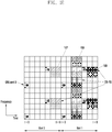
- FIGURE 1D illustrates a resource element mapping for PSS and SSS in a sub-frame for FDD according to this disclosure.
- the embodiment of the resource element mapping 190 shown in FIGURE 1D is for illustration only. Other embodiments could be used without departing from the scope of the present disclosure.
- the PSS and the SSS is mapped to the center 6 physical resource blocks (72 subcarriers) 191 in the system bandwidth 192 of the last OFDM symbol of the first slot 193 and the second last OFDM symbol of the first slot 194 of sub-frame #0 and sub-frame #5 195, respectively.
- the PSS and SSS only occupy 62 resource elements each, there are five unused resource elements 196 on each side of the PSS and the SSS.
- FIGURE 1E illustrates the resource element mapping for possible CSI-RS resources according to this disclosure.
- the embodiment of the resource element mapping shown in FIGURE 1E is for illustration only. Other embodiments could be used without departing from the scope of the present disclosure.
- the CSI-RS resources include NZP CSI-RS and ZP CSI-RS, that can be configured to the UE 116.
- a ZP CSI-RS resource is configured as a 4-port CSI-RS resource.
- One or more ZP CSI-RS resources can be configured to a UE through higher layer signaling, such as resources 197, 198, 199. For example, it is possible to configure all resource elements in the 3 rd OFDM symbol and the 4 th OFDM symbol of the second slot of a subframe to be ZP CSI-RS resources (up to six ZP CSI-RS resources can be configured in the 3 rd and the 4 th OFDM symbols of the second slot).
- a DCI for downlink assignment contains downlink scheduling information such as the rank of transmission and the Modulation and Coding Scheme (MCS) (5 bits) for each transport block that a UE shall assume for decoding the scheduled transport block.
- MCS Modulation and Coding Scheme
- the MCS indicated by an eNB for a transport block enables the UE 116 to determine the modulation order (one of QPSK, 16QAM and 64QAM) as well as the Transport Block Size (TBS), through a Modulation and TBS index table for PDSCH (Table 7.1.7.1-1 in REF 3) and one of the predefined transport block size tables depending on the number of spatial multiplexing layers (Table 7.1.7.2.1-1, Table 7.1.7.2.2-1, Table 7.1.7.2.4-1, Table 7.1.7.2.5-1 in REF 3).
- the eNB 103 can determine a rank of transmission and a MCS/TBS associated with a TB for a UE based on UE Channel State Information (CSI) measurement feedbacks, such as Rank Indicator (RI), Precoder Matrix Indicator (PMI) and Channel Quality Indicator (CQI).
- CSI Channel State Information
- RI Rank Indicator
- PMI Precoder Matrix Indicator
- CQI Channel Quality Indicator
- a CQI index is transmitted by the UE which indicates the recommended modulation order and code rate according to a 4-bit CQI table (Table 7.2.3-1 in REF 3).
- High order modulation 256 QAM is introduced for LTE for spectral efficiency enhancement.
- a PDSCH can be transmitted using 256QAM when the signal-to-noise-and-interference ratio is high (e.g. > 20dB).
- a new Modulation and TBS index table for PDSCH table that include entries corresponding to 256QAM is to be defined.
- the UE 116 uses the new table to interpret the MCS field in a DCI for PDSCH assignment.
- new TBS tables and a new CQI table include entries corresponding to 256QAM are to be defined to enable higher data rate.
- the UE 116 should not assume the new interpretation of MCS field in a DCI for all possible downlink assignment DCI formats.
- DCI formats that are used for the so-called “fallback” operation may not utilize the new table.
- “Fallback” operation allows an eNB to maintain communication with a UE regardless of the present transmission mode configuration at the UE.
- “Fallback” operation is also needed whenever there is an ambiguity about a UE's current RRC configurations which occurs naturally during a RRC reconfiguration process.
- Embodiments of the present disclosure define conditions that determine when the UE is and is not allowed to assume new interpretation of MCS field in a DCI. Embodiments of the present disclosure also define conditions that determine when the UE is and is not allowed to use the new CQI table for a CQI reporting.
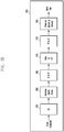
- FIGURES 2A and 2B illustrate example wireless transmit and receive paths according to this disclosure.
- a transmit path 200 may be described as being implemented in an eNB (such as eNB 102), while a receive path 250 may be described as being implemented in a UE (such as UE 116).
- the receive path 250 could be implemented in an eNB and that the transmit path 200 could be implemented in a UE.
- the transmit path 200 and receive path 250 are configured for measurement and discovery for LTE Advanced signals.
- the transmit path 200 includes a channel coding and modulation block 205, a serial-to-parallel (S-to-P) block 210, a size N Inverse Fast Fourier Transform (IFFT) block 215, a parallel-to-serial (P-to-S) block 220, an add cyclic prefix block 225, and an up-converter (UC) 230.
- S-to-P serial-to-parallel
- IFFT Inverse Fast Fourier Transform
- P-to-S parallel-to-serial
- UC up-converter
- the receive path 250 includes a down-converter (DC) 255, a remove cyclic prefix block 260, a serial-to-parallel (S-to-P) block 265, a size N Fast Fourier Transform (FFT) block 270, a parallel-to-serial (P-to-S) block 275, and a channel decoding and demodulation block 280.
- DC down-converter
- S-to-P serial-to-parallel
- FFT Fast Fourier Transform
- P-to-S parallel-to-serial
- the channel coding and modulation block 205 receives a set of information bits, applies coding (such as a low-density parity check (LDPC) coding or turbo coding), and modulates the input bits (such as with Quadrature Phase Shift Keying (QPSK) or Quadrature Amplitude Modulation (QAM)) to generate a sequence of frequency-domain modulation symbols.
- the serial-to-parallel block 210 converts (such as de-multiplexes) the serial modulated symbols to parallel data in order to generate N parallel symbol streams, where N is the IFFT/FFT size used in the eNB 102 and the UE 116.
- the size N IFFT block 215 performs an IFFT operation on the N parallel symbol streams to generate time-domain output signals.
- the parallel-to-serial block 220 converts (such as multiplexes) the parallel time-domain output symbols from the size N IFFT block 215 in order to generate a serial time-domain signal.
- the add cyclic prefix block 225 inserts a cyclic prefix to the time-domain signal.
- the up-converter 230 modulates (such as up-converts) the output of the add cyclic prefix block 225 to an RF frequency for transmission via a wireless channel.
- the signal may also be filtered at baseband before conversion to the RF frequency.
- a transmitted RF signal from the eNB 102 arrives at the UE 116 after passing through the wireless channel, and reverse operations to those at the eNB 102 are performed at the UE 116.
- the down-converter 255 down-converts the received signal to a baseband frequency
- the remove cyclic prefix block 260 removes the cyclic prefix to generate a serial time-domain baseband signal.
- the serial-to-parallel block 265 converts the time-domain baseband signal to parallel time domain signals.
- the size N FFT block 270 performs an FFT algorithm to generate N parallel frequency-domain signals.
- the parallel-to-serial block 275 converts the parallel frequency-domain signals to a sequence of modulated data symbols.
- the channel decoding and demodulation block 280 demodulates and decodes the modulated symbols to recover the original input data stream.
- Each of the eNBs 101-103 may implement a transmit path 200 that is analogous to transmitting in the downlink to UEs 111-116 and may implement a receive path 250 that is analogous to receiving in the uplink from UEs 111-116.
- each of UEs 111-116 may implement a transmit path 200 for transmitting in the uplink to eNBs 101-103 and may implement a receive path 250 for receiving in the downlink from eNBs 101-103.
- FIGURES 2A and 2B can be implemented using only hardware or using a combination of hardware and software/firmware.
- at least some of the components in FIGURES 2A and 2B may be implemented in software, while other components may be implemented by configurable hardware or a mixture of software and configurable hardware.
- the FFT block 270 and the IFFT block 215 may be implemented as configurable software algorithms, where the value of size N may be modified according to the implementation.
- variable N may be any integer number (such as 1, 2, 3, 4, or the like) for DFT and IDFT functions, while the value of the variable N may be any integer number that is a power of two (such as 1, 2, 4, 8, 16, or the like) for FFT and IFFT functions.
- FIGURES 2A and 2B illustrate examples of wireless transmit and receive paths
- various changes may be made to FIGURES 2A and 2B .
- various components in FIGURES 2A and 2B could be combined, further subdivided, or omitted and additional components could be added according to particular needs.
- FIGURES 2A and 2B are meant to illustrate examples of the types of transmit and receive paths that could be used in a wireless network. Any other suitable architectures could be used to support wireless communications in a wireless network.
- FIGURE 3 illustrates an example UE 116 according to this disclosure.
- the embodiment of the UE 116 illustrated in FIGURE 3 is for illustration only, and the UEs 111-115 of FIGURE 1 could have the same or similar configuration.
- UEs come in a wide variety of configurations, and FIGURE 3 does not limit the scope of this disclosure to any particular implementation of a UE.
- the UE 116 includes an antenna 305, a radio frequency (RF) transceiver 310, transmit (TX) processing circuitry 315, a microphone 320, and receive (RX) processing circuitry 325.
- the UE 116 also includes a speaker 330, a main processor 340, an input/output (I/O) interface (IF) 345, a keypad 350, a display 355, and a memory 360.
- the memory 360 includes a basic operating system (OS) program 361 and one or more applications 362.
- OS basic operating system
- the RF transceiver 310 receives, from the antenna 305, an incoming RF signal transmitted by an eNB of the network 100.
- the RF transceiver 310 down-converts the incoming RF signal to generate an intermediate frequency (IF) or baseband signal.
- the IF or baseband signal is sent to the RX processing circuitry 325, which generates a processed baseband signal by filtering, decoding, and/or digitizing the baseband or IF signal.
- the RX processing circuitry 325 transmits the processed baseband signal to the speaker 330 (such as for voice data) or to the main processor 340 for further processing (such as for web browsing data).
- the TX processing circuitry 315 receives analog or digital voice data from the microphone 320 or other outgoing baseband data (such as web data, e-mail, or interactive video game data) from the main processor 340.
- the TX processing circuitry 315 encodes, multiplexes, and/or digitizes the outgoing baseband data to generate a processed baseband or IF signal.
- the RF transceiver 310 receives the outgoing processed baseband or IF signal from the TX processing circuitry 315 and up-converts the baseband or IF signal to an RF signal that is transmitted via the antenna 305.
- the main processor 340 can include one or more processors or other processing devices and execute the basic OS program 361 stored in the memory 360 in order to control the overall operation of the UE 116.
- the main processor 340 could control the reception of forward channel signals and the transmission of reverse channel signals by the RF transceiver 310, the RX processing circuitry 325, and the TX processing circuitry 315 in accordance with well-known principles.
- the main processor 340 includes at least one microprocessor or microcontroller.
- the main processor 340 is also capable of executing other processes and programs resident in the memory 360, such as operations for measurement and discovery for LTE Advanced signals and performing low overhead synchronization for beam-formed systems.
- the main processor 340 can move data into or out of the memory 360 as required by an executing process.
- the main processor 340 is configured to execute the applications 362 based on the OS program 361 or in response to signals received from eNBs or an operator.
- the main processor 340 is also coupled to the I/O interface 345, which provides the UE 116 with the ability to connect to other devices such as laptop computers and handheld computers.
- the I/O interface 345 is the communication path between these accessories and the main controller 340.
- the main processor 340 is also coupled to the keypad 350 and the display unit 355.
- the operator of the UE 116 can use the keypad 350 to enter data into the UE 116.
- the display 355 may be a liquid crystal display or other display capable of rendering text and/or at least limited graphics, such as from web sites.
- the memory 360 is coupled to the main processor 340.
- Part of the memory 360 could include a random access memory (RAM), and another part of the memory 360 could include a Flash memory or other read-only memory (ROM).
- RAM random access memory
- ROM read-only memory
- FIGURE 3 illustrates one example of UE 116
- various changes may be made to FIGURE 3 .
- various components in FIGURE 3 could be combined, further subdivided, or omitted and additional components could be added according to particular needs.
- the main processor 340 could be divided into multiple processors, such as one or more central processing units (CPUs) and one or more graphics processing units (GPUs).
- FIGURE 3 illustrates the UE 116 configured as a mobile telephone or smartphone, UEs could be configured to operate as other types of mobile or stationary devices.
- CSI-RS is a physical signal measured by the UE to generate short term CSI.
- Examples of short term CSI include a Precoding Type Indicator (PTI), Rank Indicator (RI), Precoding Matrix Indicator (PMI) and Channel Quality Indicator (CQI).
- PTI Precoding Type Indicator
- RI Rank Indicator
- PMI Precoding Matrix Indicator
- CQI Channel Quality Indicator
- Short term CSI can be configured by the network when the UE is in Radio Resource Control (RRC) connected mode.
- RRC Radio Resource Control
- Configuration information for CSI-RS in LTE Rel-10 includes the number of antenna ports, the resource configuration (also called CSI RS configuration or CSI configuration, used to indicate resources within a sub-frame), the sub-frame configuration (used to indicate the sub-frames used for CSI-RS transmission by providing the periodicity and the sub-frame offset) and the parameter P c .
- Configuration for CSI-RS in LTE Rel-11 includes a CSI-RS identity, the number of antenna ports, the resource configuration, the sub-frame configuration, scrambling identity and information about CRS that is quasi co-located with the CSI-RS. (See REF 3 and REF 7).
- the RE mapping of CSI-RS is specified in REF 1 and is provided in Table 1 for the case of normal cyclic prefix, where (k',l') as defined in REF 1 represents the subcarrier index and the OFDM symbol index within a physical resource block (a block of 12 subcarriers and 0.5 ms (1 slot) duration).
- FIGURE 4A and 4B illustrate a mapping of CSI Reference Signals according to embodiments of this disclosure.
- the embodiment of the CSI Reference Signal mapping 400 shown in FIGURE 4A and 4B is for illustration only. Other embodiments could be used without departing from the scope of the present disclosure.
- the RE mapping of CSI-RS ports (labelled as port 15 to 22 in REF 1) for CSI-RS configuration 0 (i.e. resource configuration 0) is illustrated for the normal cyclic prefix.
- Certain embodiments provide new and enhanced discovery and detection methods in order to assist UE 116 to discover, or detect, and measure cells.
- the cells such as one or more of eNB 103 and FBS 160, to be detected by UE 116 are assumed to transmit signals that are then measured by UE 116.
- a candidate signal is the Channel State Information Reference Signal (CSI-RS).
- Other candidate signals are the Positioning Reference Signal (PRS), a modified PSS/SSS/CRS, or a newly designed physical signal, or a combination of the aforementioned signals.
- Cell or TP detection using discovery reference signal (DRS) includes the procedure of DRS measurement according to configuration by the network and reporting according to a predetermined or configured reporting criterion.
- transmission points also is used herein to denote “cells” that share the same Physical Cell Identity (PCI) for common signals transmissions but uses unique virtual cell id for unicast transmissions are deployed. Additional terms to which TP applies are: “cell identity”, “cell detection”, “cell measurement”, in which "cell” is replaced by “TP”, such as “TP identity”, “TP detection”, “TP measurement”.
- PCI Physical Cell Identity
- FIGURES 5 , 6 , 7 , 8 and 9 illustrate Discovery Reference Signal (DRS) occasions according to embodiments of this disclosure.
- DRS Discovery Reference Signal
- the embodiments of the DRS occasions shown in FIGURES 5 , 6 , 7 , 8 and 9 are for illustration only. Other embodiments could be used without departing from the scope of the present disclosure.
- the transmission point is eNB 103, however, the transmission point can be FBS 160 or another cell, such as a nano cell, femto cell and the like.
- N 1 for DRS occasion 500.
- N 2 for DRS occasion 600.
- the embodiments described with respect to FIGURES 5 through 9 are also referenced herein as Embodiment 1.
- UE 116 uses discovery signals 505 for cell or transmission point detection that includes one or more of: PSS, SSS, CRS and, if configured, CSI-RS.
- a discovery reference signal (DRS) occasion 500 of a cell or TP is defined as a set of consecutive DRS sub-frames (N sub-frames), transmitted periodically by eNB 103 or FBS 160, where each DRS sub-frame contains at least one of: PSS, SSS, CRS and, if configured, CSI-RS.
- the DRS occasion 500 for multiple cells or TP may or may not overlap in time. Aligning multiple DRS occasions in time especially for cells or TPs on the same frequency is beneficial from UE power saving perspective.
- DRS timing configuration can include indication of the start of a DRS occasion. If the first sub-frame of the DRS occasion always has PSS+SSS for FDD, and SSS for TDD, the DRS timing configuration can include indication of the sub-frame location of PSS+SSS for FDD, and SSS for TDD.
- the PSS, SSS, CRS, and CSI-RS are all transmitted in one sub-frame 510.
- DRS occasions of multiple cells or TPs on the same frequency can coincide in the same sub-frame or time multiplexed over at least two sub-frames 515.
- the sub-frames for DRS occasions of multiple cells/TPs can fit in a legacy measurement gap configuration.
- the DRS occasions of multiple cells or TPs in the same sub-frame can be configured (such as by RRC) for cell/TP identification and RRM measurement (CRS or CSI-RS based RSRP/RSRQ) with a DRS timing configuration.
- One DRS timing configuration may include information of only one starting sub-frame of a DRS occasion, in which case the UE 116 can be configured with multiple DRS timing configurations. In another option, one DRS timing configuration may also include information of more than one starting sub-frame of DRS occasions. For CoMP scenario 4 (or shared cell id deployment scenario), multiple CSI-RSs by the same cell (each CSI-RS corresponds to a TP) can exist.
- PSS and SSS 605 are in different sub-frames for TDD.
- the DRS timing configuration can indicate SF n and for TDD, the DRS occasions include SF n and SF n+1.
- the eNB 103 increases a number of measurement samples.
- the eNB 103 applies a transmission of a physical signal in multiple sub-frame of a DRS occasion to CSI-RS only, which is advantageous for improving the CSI-RS measurement accuracy (in the DRS occasion 705 in FIGURE 7 for FDD and in the DRS occasion 805 in FIGURE 8 for TDD).
- the eNB 103 transmits the CRS and, if configured, the CSI-RS, in multiple sub-frames of a DRS occasion, such as 5ms or 6ms of consecutive sub-frames (in the DRS occasion 710 in FIGURE 7 for FDD and in the DRS occasion 810 in FIGURE 8 for TDD).
- the eNB 103 : 1) transmits the CRS of the same cell/TP in multiple sub-frames of a DRS occasion; 2) but only transmits the CSI-RS of the same cell or TP in a subset of sub-frames, such as one sub-frame out of the DRS occasion sub-frames.
- the DRS timing configuration can also include the timing offset (ms or sub-frame) of the start of CSI-RS sub-frame relative to the starting sub-frame of the DRS occasion.
- a sub-frame is a special sub-frame for TDD
- eNB 103 does not transmit CSI-RS or the UE 116 assumes that eNB 103 does not transmit CSI-RS.
- the DRS timing configuration can indicate the first sub-frame of DRS occasions (i.e. SF n).
- DRS timing configuration can also include duration information or the number N.
- a DRS occasion can also consists of all sub-frames within the measurement gap 905 (as shown in FIGURE 9 ), in which case the measurement gap configuration can indicate the start of a DRS occasion.
- the first sub-frame of a DRS occasion can carry the PSS and the SSS.
- the first sub-frame of a DRS occasion can carry the SSS and the second sub-frame of a DRS occasion can carry the PSS. This is advantageous to enable the UE 116 to perform synchronization with the PSS/SSS first before receiving CRS and/or CSI-RS.
- multiple CSI-RSs by the same cell can exist.
- sub-frame n can either be sub-frame 0 or sub-frame 5, such that the location of PSS or SSS indicates the possible sub-frame index of the cell or TP detected.
- SF n+1 is a special sub-frame.
- SF n+1 can also be the DL sub-frame for certain TDD configurations such as configuration 3, 4, and 5, hence CSI-RS can be transmitted in SF n+1 as well.
- UE assumes that CSI-RS is not present in the sub-frame or in the resource blocks where PBCH may be present.
- UE 116 determines (or assumes) that CSI-RS is present as in other sub-frames and the PBCH is determined (or assumed) to not be present.
- the network explicitly indicates a presence of CSI-RS in SF n , by higher layer signaling, such as RRC.
- UE 116 When the absence of CSI-RS is indicated for SF n , then UE 116 skips SF n when receiving CSI-RS. Alternatively, when the absence of CSI-RS is indicated for SF n , UE 116 also receives CSI-RS in SF n .
- eNB 103 when a DRS occasion contains multiple sub-frames with CSI-RS, eNB 103 enables configuration of multiple (consecutive) Zero-Power CSI-RS sub-frames with a single ZP-CSI-RS resource or configuration. In this way, when a eNB 103 configures this new ZP-CSI-RS configuration according to the CSI-RS patterns of DRS of its neighboring cells or TPs, the CSI-RS of DRS of neighboring cells/TPs is protected from interference of eNB 103, the configuring cell/TP.
- the UE 116 configured with this new ZP-CSI-RS configuration, is configure to assume that the corresponding ZP-CSI-RS REs are not used for data transmission and can be skipped when performing rate matching operation.
- the maximum number of ZP CSI-RS configurations that can be configured to a UE can be kept the same at 4 (as specified in Rel-11 LTE).
- the new ZP-CSI-RS configuration can be realized by introducing a new RRC information element (IE) to the existing ZP-CSI-RS configuration IE (CSI-RS-ConfigZP-r11).
- the new RRC ID is configured to indicate a duration or length of the ZP-CSI-RS sub-frames (e.g. 1 ms or 2ms or 5ms).
- the maximum number of ZP CSI-RS configurations that can be configured to a UE can be increased from 4 (as specified in Rel-11 LTE) to a larger number, such as, 20.
- FIGURE 10 illustrates an enhanced CSI-RS with 4 resource elements per physical resource block pair according to embodiments of the present disclosure.
- the embodiments of the enhanced CSI-RS structures 1000, 1005 shown in FIGURE 10 are for illustration only. Other embodiments could be used without departing from the scope of the present disclosure.
- the CSI-RS (for example, the CSI-RS of the DRS occasion) is assumed as the signal used for cell detection, transmit point (TP) detection, or a combination of cell and TP detection, for descriptions of the embodiments of the present disclosure, unless stated otherwise. It is noted that the principles of the embodiments of the present disclosure are applicable also to other type of signals used for cell detection, including the CRS of DRS occasion and any enhanced CSI-RS design, such as as described in REF 10, where the density of the CSI-RS is proposed to be increased in the frequency domain to 4 REs per PRB-pair (resembling 4-port mapping) or 8 REs per PRB-pair (resembling 8-port mapping) as shown in FIGURE 10 .
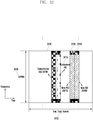
- the periodicity of the enhanced CSI-RS transmission is modified to have lower duty cycle T 1105 so as to minimize network and UE power consumption as shown in FIGURE 11 .
- the enhanced CSI-RS design with higher frequency density, as described in REF 10 improves a detection performance due to a larger number of samples.
- using the enhanced CSI-RS also minimizes a performance impact to the legacy UEs since the enhanced CSI-RS resources can be configured as zero power CSI-RS resources. Additional methods to enhance CSI-RS for the purpose of cell detection and discovery are described in herein below with respect to FIGURE 17 .
- description of the discovery signal with reference to the CSI-RS does not necessarily imply that a respective structure will be same as for a conventional CSI-RS.
- an enhanced CSI-RS structure 1000, 1005 can be used.
- the network can configure UE 116 to detect and measure CSI-RSs from multiple cells that include neighboring cells, such as small cells, eNB 102 and eNB 101, and optionally, one or more serving cells, such as FBS 160 or eNB 103, to generate a signal quality measurement such as RSRP and/or Reference Signal Received Quality (RSRQ) and/or SINR of each cell.
- the cells to be detected and measured by the UE 116 can be from a same cluster of small cells or can be from multiple clusters of small cells.
- the UE 116 reports measurement results to the network when a reporting criterion is met. For example, UE 116 can be triggered to transmit a measurement reporting when a RSRP value is greater than a threshold.
- the threshold is configured by the network. In certain embodiments, the threshold is pre-configured. In certain embodiments, when the UE 116 does not have a PUSCH transmission, UE 116 transmits a service request, in a PUCCH, requesting a scheduling from a network for a PUSCH transmission in order to report measurement results for discovery signals. In certain embodiments, the UE 116 is configured by the network with a PUCCH resource or a PUSCH resource to use for reporting measurement results of discovery signals. The PUCCH or PUSCH resource is valid only for a sub-frame occurring after sub-frame(s) of transmissions of discovery signals and, therefore, an associated overhead for reporting measurement results is low.
- Embodiments of the present disclosure specify CSI-RS resource configuration method for cell detection purpose. Embodiments of the present disclosure also enable UE 116 to determine the identity of a cell transmitting a CSI-RS the UE detects. In certain embodiments, the UE 116 includes the identity of the cell in the measurement report so that the network is able to associate the measurement report with the corresponding cell identity. When the UE 116 detects multiple cells, the UE 116 reports a predetermined maximum number of the detected cells. The report from UE 116 can always include measurements for the predetermined maximum number of cells or a header can inform the network of the number of reported cells.
- the network configures the UE 116 to detect and measure multiple CSI-RS resources.
- the network can configure the UE 116 by higher layer signaling such as RRC signaling or MAC signaling.
- Each CSI-RS resource configuration consists of an identity of a CSI-RS resource, a resource configuration, a sub-frame configuration and a scrambling identity (used for generating a scrambling sequence for the CSI-RS).
- the UE 116 is configured to assume that a number of CSI-RS ports is one. In certain embodiments, a number of CSI-RS ports are also signaled to the UE 116.
- the network can also signal an index ([0, 1]) of a length-2 Orthogonal Cover Code (OCC).
- OCC Orthogonal Cover Code
- the UE 116 blindly detects an index for an OCC applied to a CSI-RS. In either case, the UE 116 is configured to recognize a cell with a single CSI-RS port that is spread with an OCC [1 -1] over consecutive symbols.
- the UE 116 is configured to assume that no OCC is applied or assumes a fixed OCC is applied, such as [1 1].
- csi-RS-ConfigNZPld-rxy represents the identity of the CSI-RS resource
- resourceConfig-rxy represents the resource configuration (also called CSI RS configuration or CSI configuration)
- sub-frameConfig-rxy represents the sub-frame configuration
- scramblingldentity-rxy represents the scrambling identity (may also be called the physical cell identity (PCID), virtual cell id (VCID), cell id (CID)):
- a list of CSI-RS resources is configured for detection of multiple CSI-RSs or cells, as illustrated by an example ASN.1 code below, by configuring the UE 116 with csi-RS-ConfigNZPToAddModList-rxy.
- csi-RS-ConfigNZPToAddModList-rxyCSI-RS-ConfigNZPToAddModList-rxyOPTIONAL,-- Need CSI-RS-ConfigNZPToAddModList-rxy :: SEQUENCE (SIZE (1..maxCSI-RS-NZP-rxy)) OF CSI-RS-ConfigNZP-rxy
- the discovery signals of multiple cells are transmitted in a same sub-frame or same set of OFDM symbols so as to minimize the wake up time for the UE 116 to detect the discovery signals, which in turn saves UE power consumption. Therefore, it can be typical that the same sub-frame configuration is applied for the CSI-RS resources of multiple cells.
- the sub-frame configuration for a group of cells with a same configuration is signalled only once, while the other configuration fields are signalled per CSI-RS resource, for example, as shown in an example ASN.1 code below, where CSI-RS-CommonConfigNZP-rxy is the container for common configuration (in this case, sub-frameConfig-rxy) of multiple CSI-RS resources and CSI-RS-ConfigNZPList-rxy specifies a list of CSI-RS resources where the common configuration is applicable. If the common configuration is always applicable for all CSI-RS resources configured, the indication of a list may not be needed.
- the scrambling identity is included as part of the common signalling.
- the UE 116 uses the indicated scrambling identity to detect the set CSI-RS resources configured.
- Common scrambling identity reduces CSI-RS detection complexity and improves detection performance.
- An example ASN.1 code is given below.
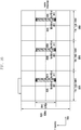
- FIGURE 12 illustrates different sub-frame configurations for different groups of small cells according to this disclosure.
- the embodiment of the sub-frame configurations 1200 shown in FIGURE 12 is for illustration only. Other embodiments could be used without departing from the scope of the present disclosure.
- the UE 116 may need to detect cells that do not share a same CSI-RS common configuration.
- different sub-frame configurations can be configured for different groups or clusters of small cells as shown in FIGURE 12 .
- a first CSI-RS transmission 1205 can be configured for a first group of cells while a second CSI-RS transmission 1210 is configured for a second group of cells.
- the UE 116 can be configured with multiple CSI-RS common configurations, each being applied to a separate set of CSI-RS resources.
- Method 2 the network configures a sub-frame configuration for CSI-RS(s) to be detected by the UE 116 but not their resource configurations or OCC indices.
- Method 2 A difference with respect to Method 1 is that the UE 116 is not informed which REs of the CSI-RS sub-frames (determined by resource configuration) contain CSI-RS. The UE 116 is required to try to detect the presence of a CSI-RS in the CSI-RS sub-frames determined by the sub-frame configuration.
- 40 possible CSI-RS resources can exist in a sub-frame for normal CP that the UE 116 needs to try to detect (each cell's CSI-RS occupies one CSI-RS port, there are 20 unique time-frequency RE-pair locations and 2 time-domain orthogonal cover code for each time-frequency RE-pair).
- 20 possible CSI-RS resources exist in a sub-frame for normal CP that the UE 116 needs to try to detect (each cell's CSI-RS occupies one CSI-RS port, there are 20 unique time-frequency RE-pair locations and only one time-domain orthogonal cover code is used for each time-frequency RE-pair, such as [1 1]).
- all the CSI-RS resources corresponding to the sub-frame configuration can have the same scrambling identity for sequence generation.
- the scrambling identity can also be provided as shown in the example ASN.1 code below. Scrambling identity can be seen as a group-common scrambling identity.
- all the CSI-RS resources corresponding to the sub-frame configuration can have different scrambling identities.
- the scrambling identity is not provided as shown in the example ASN.1 code below.
- the CSI-RS detection configuration can also include a CSI-RS group identity (csi-RS-GroupConfigNZPld-rxy).
- a CSI-RS group can consist of a group of CSI-RS resources to be detected by the UE 116.
- a CSI-RS group can correspond to the CSI-RS transmitted by small cells in the same cluster as shown in FIGURE 12 .
- the CSI-RS transmitted by small cells in the same cluster can correspond to the first CSI-RS transmission 1205 for the first group of cells.
- the CSI-RS transmitted by small cells in the same cluster can correspond to the second CSI-RS transmission 1210 for the second group of cells.
- Each CSI-RS group can be associated with or configured with a set of PCIs of which the corresponding PSS/SSS can be assumed by the UE 116 for coarse time and frequency synchronization (as illustrated in Embodiment 2 herein below).
- the coordination among cells regarding the CSI-RS transmission have the advantage of only needing to involve the sub-frames used for CSI-RS transmissions, but not the actual RE locations of the CSI-RS; therefore eNB 103 is free to reconfigure a resource configuration of its own CSI-RS without informing other eNodeBs, such as eNB 101 or eNB 102.
- the network also can signal multiple CSI-RS sub-frame configurations, such as by signaling a list of CSI-RS configurations, if the number of CSI-RS resources to be searched exceeds the maximum number of CSI-RS resources for a sub-frame configuration.
- the possible CSI-RS resources defined by the CSI-RS sub-frame configuration constitute the CSI-RS search space.
- the neighboring eNodeBs such as eNB 101 and eNB 102, can exchange information on the respective CSI-RS configurations so that each eNodeB can configure to their respective UEs the appropriate CSI-RS configurations.
- a large CSI-RS search space increases UE signal processing time.
- the large CSI-RS search space also increases false alarm probability.
- the network signals a reduced set of resources to be searched by UE 116.
- the network can indicate to the UE 116 that a total number of CSI-RS resources to be searched is 20 and the UE 116 only searches in the first 20 CSI-RS resource locations.
- the network additionally signals a starting position for CSI-RS resources to be searched.
- embodiments of the present disclosure define an ordering/labeling of CSI-RS resources (CSI-RS resource indexing) so that UE 116 is able to understand the signaling by the network.
- the ordered CSI-RS resources are labeled with an index, called CSI-RS index.
- This mapping of CSI-RS index and physical resource is represented in Table 2. This ordering or mapping method minimizes the use of code-division multiplexing for CSI-RS resources, which helps to improve detection robustness for CSI-RS resources detection considering a time or a frequency offset.
- CSI-RS index 1 - 20 are applicable.
- CSI-RS index Frequency and time location OCC[W 0 W 1 ] (k',l') n s mod 2 1 (2,5) 0 [1 1] 2 (3,5) 0 [1 1] 3 (8,5) 0 [1 1] 4 (9,5) 0 [1 1] 5 (0,2) 1 [1 1] 6 (1,2) 1 [1 1] 7 (2,2) 1 [1 1] 8 (3,2) 1 [1 1] 9 (4,2) 1 [1 1] 10 (5,2) 1 [1 1] 11 (6,2) 1 [1 1] 12 (7,2) 1 [1 1] 13 (8,2) 1 [1 1] 14 (9,2) 1 [1 1] 15 (10,2) 1 [1 1] 16 (11,2) 1 [1 1] 17 (2,5) 1 [1 1] 18 (3,5) 1 [1 1] 19 (8,5) 1 [1 1] 20 (9,5) 1 [1 1] 21 (2,5) 0 [1 -1] 22 (3,5) 0 [1 -1] 23 (8,5) 0 [1 -1] 20
- CSI-RS index Frequency and time location OCC[w 0 w 1 ] (k',l') n s mod 2 1 (0,2) 1 [1 1] 2 (1,2) 1 [1 1] 3 (2,2) 1 [1 1] 4 (3,2) 1 [1 1] 5 (4,2) 1 [1 1] 6 (5,2) 1 [1 1] 7 (6,2) 1 [1 1] 8 (7,2) 1 [1 1] 9 (8,2) 1 [1 1] 10 (9,2) 1 [1 1] 11 (10,2) 1 [1 1] 12 (11,2) 1 [1 1] 13 (2,5) 0 [1 1] 14 (3,5) 0 [1 1] 15 (8,5) 0 [1 1] 16 (9,5) 0 [1 1] 17 (2,5) 1 [1 1] 18 (3,5) 1 [1 1] 19 (8,5) 1 [1 1] 20 (9,5) 1 [1 1] 21 (0,2) 1 [1 -1] 22 (1,2) 1 [1 -1] 23 (2,2) 1 [1 -1] 24
- the ordering is represented in Table 4.
- CSI-RS index Frequency and time location OCC[w 0 w 1 ] (k',l') n s mod 2 1 (2,5) 0 [1 1] '2 (2,5) 0 [1 -1] 3 (3,5) 0 [1 1] 4 (3,5) 0 [1 -1] 5 (8,5) 0 [1 1] 6 (8,5) 0 [1 -1] 7 (9,5) 0 [1 1] 8 (9,5) 0 [1 -1] 9 (0,2) 1 [1 1] 10 (0,2) 1 [1 -1] 11 (1,2) 1 [1 1] 12 (1,2) 1 [1 -1] 13 (2,2) 1 [1 1] 14 (2,2) 1 [1 -1] 15 (3,2) 1 [1 1] 16 (3,2) 1 [1 -1] 17 (4,2) 1 [1 1] 18 (4,2) 1 [1 -1] 19 (5,2) 1 [1 1] 20 (5,2) 1 [1 -1] 21 (6,2) 1 [1 1] 22 (6,2) 1 [1 [1]
- CSI-RS index Frequency and time location OCC[w 0 w 1 ] (k',l') n s mod 2 1 (2,5) 0 [1 1] 2 (2,5) 0 [1 -1] 3 (3,5) 0 [1 1] 4 (3,5) 0 [1 -1] 5 (8,5) 0 [1 1] 6 (8,5) 0 [1 -1] 7 (9,5) 0 [1 1] 8 (9,5) 0 [1 -1] 9 (0,2) 1 [1 1] 10 (0,2) 1 [1 -1] 11 (1,2) 1 [1 1] 12 (1,2) 1 [1 -1] 13 (2,2) 1 [1 1] 14 (2,2) 1 [1 -1] 15 (3,2) 1 [1 1] 16 (3,2) 1 [1 -1] 17 (4,2) 1 [1 1] 18 (4,2) 1 [1 -1] 19 (5,2) 1 [1 1] 20 (5,2) 1 [1 -1] 21 (6,2) 1 [1 1] 22 (6,2) 1 [1 -1] 19
- the principles described here can easily extend to other CSI-RS resource mapping defined in LTE Rel-10/11 (that is, mapping for extended CP and for other TDD mapping). It is also noted that the methods described here can easily extend to mapping of CSI-RS resources of multiple sub-frame configurations to CSI-RS indices, that is, the CSI-RS index is unique for CSI-RS resources from multiple sub-frame configurations.
- the CSI-RS index mapping can be applied for a DRS timing configuration which is associated with a group of DRS occasions or a group of CSI-RS resources.
- the network signals, such as via higher layer signaling, piece-wise ranges of CSI-RS resource positions to be searched by the UE 116.
- a CSI-RS resource ordering in a sub-frame can be as previously described.
- the network can signal that CSI-RS resources are from 1 to 5 and from 10 to 20 (assuming the first CSI-RS resource is labeled as 1).
- N ID CSI which is the same as the scrambling identity of the CSI-RS as defined in TS 36.331 V11.3.0, takes a value from 0 to 503 (or the scramblingldentity-rxy above).
- the UE 116 tries to detect a presence of CSI-RS with N lD CSI from 0 to 503 (with non-coherent detection techniques) or with a single indicated N ID CSI value.
- the network reduces the possible N lD CSI to be searched by the UE 116.
- a range of N ID CSI can be signaled, such as by higher layer signaling, given by a starting value and a range value.
- the UE 116 is signaled by higher layers an explicit set of N ID CSI values.
- Certain embodiments illustrate a relationship between the CSI-RS index and N D CSI .
- the UE 116 is either signaled separately a set CSI-RS indices and a set of N ID CSI to be searched or the UE 116 is configured to assume a valid range for each parameter without signaling.
- the UE 116 also can be signaled a mapping between a CSI-RS index and a N lD CSI to a PCI (see Table 6 & Table 7 for two examples), such as via RRC signaling or via a predefined mapping table (cell identification table). Mapping of multiple CSI-RS resources to a PCI is also possible for certain deployment scenarios (such as, CoMP scenario 4 as described in REF 11) (see also Table 8).
- the sub-frame configuration also is included in the mapping to PCI as illustrated in Table 11 (Table 9 and Table 10 illustrate when a mapping of multiple CSI-RS resources to a PCI is possible.)
- the UE 116 also can be signaled a set of PCIs and the UE 116 is configured to determine the set of CSI-RS resources to be detected.
- the UE 116 detects a CSI-RS resource, the UE 116 is configured to determine the PCI detected, that is, the mapping of CSI-RS resource to PCI allows cell identification.
- CSI-RS resource N ID CSI CSI-RS index PCI Resource 1 Scrambling id 1 1 PCI 1 Resource 2 Scrambling id 1 2 PCI 2 Resource 3 Scrambling id 1 3 PCI 3 Resource 4 Scrambling id 2 4 PCI 4 Resource 5 Scrambling id 2 5 PCI 5 Resource 6 Scrambling id 2 6 PCI 6 Mapping between a CSI-RS index and a N ID CSI to a PCI
- CSI-RS resource N ID CSI CSI-RS index PCI Resource 1 Scrambling id 1 1 PCI 1 Resource 2 Scrambling id 2 2 PCI 2 Resource 3 Scrambling id 3 3 PCI 3 Resource 4 Scrambling id 4 4 PCI 4 Resource 5 Scrambling id 5 5 PCI 5 Resource 6 Scrambling id
- Quasi co-location of PSS/SSS/CRS/DM-RS ports associated with PCI and CSI-RS ports also can be defined using the mapping tables.
- a CSI-RS resource 1 that is mapped to a PCI 1 means that PSS/SSS/CRS/DM-RS associated with PCI 1 can be assumed by the UE 116 to be quasi co-located with CSI-RS resource 1 in terms of delay spread, Doppler spread, Doppler shift, average gain, and average delay.
- a CSI-RS resource 1 that is mapped to a PCI 1 means that PSS/SSS/CRS/DM-RS associated with PCI 1 can be assumed by the UE 116 to be quasi co-located with CSI-RS resource 1 in terms of Doppler shift and average delay. Further signaling support can be provided if there is a need to address deployment scenarios such as CoMP scenario 4.
- Quasi-co-location (QCL) type signaling can be provided to indicate if the QCL linkage between a CSI-RS resource and PSS/SSS/CRS/DM-RS associated with a PCI is based on a first type (Type 1) or a second type (Type 2) (see Table 10). For example:
- the QCL linkage can improve reception performance of CSI-RS resource by exploiting the QCL relationship with detected PSS/SSS/CRS/DM-RS and vice versa.
- the CSI-RS resource can include RSRP measurement based on CSI-RS.
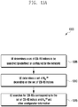
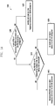
- FIGURE 13A illustrates a process 1300 to determine as set of values to be searched from a set of CSI-RS indices according to this disclosure.
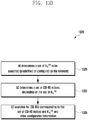
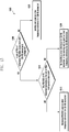
- FIGURE 13B illustrates a process 1305 to determine a set of CSI-RS indices to be searched from a set of values according to this disclosure. While the flow charts depict a series of sequential steps, unless explicitly stated, no inference should be drawn from that sequence regarding specific order of performance, performance of steps or portions thereof serially rather than concurrently or in an overlapping manner, or performance of the steps depicted exclusively without the occurrence of intervening or intermediate steps.
- the processes depicted in the examples depicted are implemented by a transmitter chain in, for example, a mobile station or a base station.
- relation/mapping between CSI-RS index and N lD CSI is defined to save signaling overhead such that the UE 116 is able to determine a set of CSI-RS indices to be searched from the signaling of a set of N ID CSI and vice versa as shown in FIGURES 13A and 13B .
- the CSI-RS index is determined from N ID CSI of the corresponding CSI-RS.
- the network can either signal a range or a set of N ID CSI values to be detected by a UE 116, as well as the sub-frame configuration.
- the UE 116 is configured to determine a set of CSI-RS resources in the corresponding sub-frames for detection and measurement.
- the network signals a range or a set of CSI-RS indices to be detected by the UE 116 as well as the sub-frame configuration.
- the UE 116 also is configured to determine the scrambling identities (e.g., N lD CSI ) to attempt CSI-RS detection for a given CSI-RS index in block 1325. Extension of this method to map CSI-RS index defined uniquely over multiple sub-frame configurations to N lD CSI in block 1330. The mapping of CSI-RS index over multiple sub-frame configurations to N ID CSI is straightforward.
- This method has an advantage of reducing the CSI-RS searching complexity for the UE 116 in block 1335, improving detection performance by reducing the number of candidates as well as reducing signaling over X2 or between the eNB 103 and the UE 116.
- N is less than the number of possible values for N ID CSI
- the UE 116 can blindly detect N ID CSI of the CSI-RS corresponding to the CSI-RS index in block 1315.
- the resource elements configured, or potentially configured, for CSI-RS transmission are configured by the network to be zero-power CSI-RS resources for UEs, such that UE 116 does not assume an existence of other useful physical signals in the corresponding resource elements.
- Symbols for physical channels, such as PDSCH and EPDCCH, are not mapped onto the configured zero-power CSI-RS resources.
- configuration messages are delivered in a UE-dedicated RRC signaling.
- configuration messages are delivered in a broadcast channel (as part of an existing or new System Information Block).
- Certain embodiments provide, for all methods of CSI-RS detection configuration, support for on-demand measurement report request to allow the network the flexibility to obtain an up-to-date measurement report in a timely manner, such as for deciding if a cell that has been in dormant state, but is still transmitting the discovery signal, should be turned on or not.
- the UE 116 can be signaled a request to prepare for an on-demand measurement report via paging or dynamic control channel (PDCCH/EPDCCH).
- a discovery signal is expected by the UE 116 to be transmitted in a predetermined later time (such as 10ms after the reception of the request).
- the timing of the discovery transmission upon reception of a request can either be predefined (fixed) or can be configurable by the network.
- the UE 116 is configured to attempt to detect and measure the discovery signals at the time determined and report its measurement results and the identities of the discovery signals detected.
- configuration messages are also included in a handover command. Therefore, the UE 116 is able to perform CSI-RS detection as soon as possible during or after a handover procedure.
- Certain embodiments for all methods of CSI-RS or TP detection configuration, define how an identity of a CSI-RS resource or TP is defined in a measurement report.
- an identity of a CSI-RS resource (which allows the network to identify uniquely the cell detected) to be included in the measurement report can be different.
- the UE 116 reports the CSI-RS resource configuration, the scrambling identity and OCC index, together with the measurement result (e.g. RSRP/RSRQ), in a measurement report for the detected CSI-RS.
- the measurement result e.g. RSRP/RSRQ
- the UE 116 reports the CSI-RS index and the corresponding measurement results.
- the measurement results can be, for example, the RSRP/RSRQ.
- the UE 116 reports the scrambling identity and the corresponding measurement results, such as RSRP/RSRQ.
- the scrambling identities can be reused in different group of CSI-RS resources (representing different small cell cluster or a different group of transmission points in CoMP scenario 4) (that is, a CSI-RS scrambling identity is only unique within a CSI-RS group)
- the PCI of the PSS/SSS used as coarse time and frequency synchronization for the CSI-RS detection also is reported.
- the CSI-RS group index can be reported.
- the sub-frame configuration of the detected CSI-RS can be reported.
- the CSI-RS resource is uniquely identified by a combination of its CSI-RS index and its scrambling identity.
- the UE 116 reports the CSI-RS index as well as the scrambling identity and the corresponding measurement results, such as RSRP/RSRQ. If a mapping between a combination of a CSI-RS index and a scrambling identity to a PCI is commonly known at the eNB 103 and the UE 116, via RRC signaling or via a predetermined mapping table (Table 6), then the UE 116 can just report the PCI and the corresponding measurement results, such as RSRP/RSRQ.
- the CSI-RS resource is uniquely identified by a combination of its CSI-RS index, its scrambling identity and its sub-frame configuration.
- the UE 116 reports the CSI-RS index, the scrambling identity, the sub-frame configuration and the corresponding measurement results, such as RSRP/RSRQ.
- a mapping between a combination of a CSI-RS index, a scrambling identity and sub-frame configuration to a PCI is commonly known at the eNB 103 and the UE 116, via RRC signaling or via a predetermined mapping table (Table 11), then the UE 116 is configured to report the PCI and the corresponding measurement results, such as RSRP/RSRQ.
- the measurement report can include, for example, CSI-RS-CommonConfigNZPld-rxy of Method 1 or CSI-RS-GroupConfigNZPld-rxy of Method 2, as described above.
- the UE 116 when mapping of a CSI-RS resource identity and PCI is provided, via RRC signaling or via a predetermined mapping table, the UE 116 is configured to just report the PCI and the corresponding measurement results, such as RSRP/RSRQ, when the mapping is one-to-one. Otherwise, the UE 116 is configured to report additional information pertaining to the CSI-RS resource, which also needs to be reported. That is, the UE 116 can report the CSI-RS index, a CSI-RS scrambling id, a virtual id, or a combination thereof.
- a CSI-RS resource id or a TP id can be uniquely assigned to each CSI-RS resource or TP, as shown in the first column of Table 6, Table 7, Table 8, Table 9, Table 10 and Table 11.
- the UE 116 is configured to just report CSI-RS resource id or TP id and the corresponding measurement results, such as RSRP/RSRQ.
- Embodiment 2 Time and frequency reference for CSI-RS: when significant time and/or frequency offsets are present at a receiver in UE 116 when receiving a signal, the receiver performance will be degraded if the offsets are not compensated.
- a network it may not be possible for a network to ensure that CSI-RS detectable by the UE 116 are synchronized sufficiently in time (such as ⁇ 3 ⁇ s) and/or frequency (such as ⁇ 0.1 ppm) with respect to the serving cell in order to meet the minimum performance requirement for detection and measurement.
- a group of cells interconnected with high capability backhaul such as a fiber optic connection or the like, can be sufficiently synchronized to a reference cell, which may not be the serving cell of the UE 116. Therefore, in order to facilitate accurate detection and measurement performance by the UE 116, embodiments of the present disclosure provide a reference cell for synchronization for either time or frequency or both time and frequency, that the UE 116 is configured to assume when measuring a CSI-RS signal. In one option, the UE 116 is configured to assume that a target cell and its reference cell are synchronized to an extent to provide sufficiently accurate RRM measurement. For example, a timing difference is within ⁇ 3 ⁇ s and frequency difference is within ⁇ 0.1 ppm.
- the synchronization of the target cell and its reference cell may not be enough to meet the minimum performance requirement for data demodulation or the signals from the target cell and its reference cell may not be assumed to quasi co-located in terms of some large scale channel properties, which includes one or more of delay spread, Doppler spread, Doppler shift, average gain, and average delay.
- the UE 116 is configured to assume that the signals from the target cell and its reference cell are only quasi co-located in terms of Doppler shift and average delay.
- the UE 116 is configured to assume that the target cell and its reference cell are synchronized to an extent that can meet the minimum performance requirement for data demodulation.
- the UE 116 is configured to assume that the signals from the target cell and its reference cell are quasi co-located in terms of some large scale channel properties, which includes one or more of delay spread, Doppler spread, Doppler shift, average gain, and average delay.
- the UE may only reliably detects few small cells using PSS/SSS/CRS.
- a small cell such as FBS 160, that cannot be easily detected by the UE 116, transmits CSI-RS to facilitate detection by the UE 116.
- small cells in a cluster can be sufficiently synchronized in time and/or frequency. Therefore, UE 116 is configured to use one or multiple PSS/SSS/CRSs detected from any small cells in the cluster as the reference for detecting a CSI-RS of a small cells that otherwise cannot be detected by the UE 116 through only PSS/SSS/CRS.
- the UE 116 uses the strongest PSS/SSS/CRS signals as the reference or combines the reference signals detected to derive the reference time/frequency. As such, in certain embodiments for the cell discovery procedure, UE 116 is configured to assume multiple signals are transmitted, where a first signal or signals is the PSS/SSS/CRS, and the second signal is the CSI-RS (or other physical signals that can replace CSI-RS).
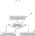
- FIGURE 14 illustrates a UE process 1400 for determining a reference time or reference frequency for CSI-RS detection according to embodiments of the present disclosure. While the flow chart depicts a series of sequential steps, unless explicitly stated, no inference should be drawn from that sequence regarding specific order of performance, performance of steps or portions thereof serially rather than concurrently or in an overlapping manner, or performance of the steps depicted exclusively without the occurrence of intervening or intermediate steps.
- the process depicted in the example depicted is implemented by a receiver chain or processing circuitry in, for example, a mobile station.
- the network provides a physical cell identity or a set of physical cell identities of the reference PSS/SSS for each or for a set of CSI-RS resources to be detected by UE 116.
- the set of CSI-RS resources to be searched by a UE can be as described herein above in Embodiment 1, with respect to FIGURES 5 through 9 .
- the PCIs of the reference PSS/SSS/CRS can be the same as the PCIs associated with the CSI-RS resources to be searched, such as illustrated in Table 6.
- the PCI of the reference PSS/SSS/CRS for each CSI-RS resource can be the same as the PCI associated with the CSI-RS resource such as illustrated in Table 6, Table 7, Table 8, Table 9, Table 10 and Table 11.
- the set of PCIs of the reference PSS/SSS/CRS for each CSI-RS resource can be the same as all or a subset of PCIs included in the mapping table such as illustrated in Table 7, Table 8, Table 9, Table 10 and Table 11, which can be advantageous if all CSI-RS resources are from the same cell cluster and hence are approximately synchronized (for example, the reference PSS/SSS/CRS and the corresponding CSI-RS are quasi co-located in terms of average delay and Doppler shift).
- the PCIs of the reference PSS/SSS/CRS for a cell can be the same as the PCIs associated with CSI-RS resources belonging to the same sub-frame configuration.
- PCI 1 - 6 are the references for any CSI-RS resource 1-6 and PCI 7-12 are the references for any CSI-RS resource 7-12.
- the PCIs of reference PSS/SSS/CRS also can be explicitly signaled by the network, such as via RRC, as shown in Table 12, where each CSI-RS resource has a set of reference PCIs.
- Table 13 Another example is illustrated in which the RRC signaling indicates the mapping of a set of CSI-RS resources to a set of reference PCIs.
- Table 14 is illustrated in which the RRC signaling indicates the mapping of a set of CSI-RS resources to a single reference PCI.
- Table 14 can be suitable for deployment scenarios where multiple transmission points are associated with the same PCI (such as CoMP scenario 4).
- Table 12 CSI-RS resource Reference PCIs 1 1 - 6 2 1 - 6 3 1 - 6 4 1 - 6 5 1 - 6 6 1 - 6 7 7 -12 8 7 -12 9 7 -12 10 7 -12 11 7 -12 12 7 -12 Reference PCIs signaling
- Table 13 CSI-RS resource Reference PCIs 1-6 1 - 6 7-12 7 -12 Reference PCIs signaling
- Table 14 CSI-RS resource Reference PCIs 1-6 1 7-12 2 Reference PCIs signaling
- the UE 116 is configured with a set of PCIs of reference PSS/SSS/CRSs associated with CSI-RS resource.
- the UE 116 Upon receiving the signaling of the reference PSS/SSS/CRS PCIs for a CSI-RS resource in block 1405, the UE 116 is configured to assume a same time and/or frequency reference for receiving a corresponding CSI-RS based on PSS/SSS/CRSs detected with a same PCI (for example, the reference PSS/SSS/CRS and the corresponding CSI-RS are quasi co-located in terms of average delay and Doppler shift).
- the UE 116 can use the strongest PSS/SSS/CRS signals as the reference or combine the reference signals detected to derive the reference time/frequency in block 1415. For example, UE 116 can use PSS/SSS detected for coarse time synchronization, and use CRS detected for coarse frequency synchronization. When none of PSS/SSS/CRS of indicated PCIs has been detected by the UE 116 in block 1410, the UE 116, in block 1420, does not attempt to detect the CSI-RS configured.
- the UE 116 can skip detecting corresponding CSI-RS resources as this may imply that the cells concerned belong to small cells that are beyond coverage from where the UE 116 is located. This is the case if one or more cell within a cluster always exists to transmit the PSS/SSS(/CRS) or if the PSS/SSS/CRS are part of the DRS as shown in FIGURES 5 through 9 .
- the UE 116 is not configured with the reference PSS/SSS/CRS PCIs for a CSI-RS resource in block 1405, the UE 116 proceeds to block 1425 and uses the eNB 103 (the serving cell) as a time/frequency reference for CSI-RS detection.
- FIGURE 15 illustrates 1500 another UE process for determining a reference time or reference frequency for CSI-RS detection according to embodiments of the present disclosure. While the flow chart depicts a series of sequential steps, unless explicitly stated, no inference should be drawn from that sequence regarding specific order of performance, performance of steps or portions thereof serially rather than concurrently or in an overlapping manner, or performance of the steps depicted exclusively without the occurrence of intervening or intermediate steps.
- the process depicted in the example depicted is implemented by a receiver chain or processing circuitry in, for example, a mobile station.
- the UE 116 is configured with a set of PCIs of reference PSS/SSS/CRSs associated with CSI-RS resource in block 1505.
- the UE 116 attempts to detect PSS/SSS of PCI belonging to the set of PCIs in block 1510.
- the UE 116 can use the strongest PSS/SSS/CRS signals as the reference or combine the reference signals detected to derive the reference time/frequency in block 1515.
- UE 116 can use PSS/SSS detected for coarse time synchronization, and use CRS detected for coarse frequency synchronization.
- the UE 116 When not detecting any PSS/SSS/CRS of indicated PCIs in block 1510, which may mean that all the cells concerned are currently in dormant mode, the UE 116 is configured to not assume any reference for the CSI-RS resources in block 1520.
- the serving cell can be used as the time/frequency reference for the CSI-RS resources, or that the appropriate assumption can be configurable by the network.
- the UE 116 is configured to detect CSI-RS without a time/frequency reference or using the serving cell as the reference if none of PSS/SSS/CRS of reference PCIs has been detected by the UE 116.
- network signaling can be provided to assist the UE 116 in distinguishing the two scenarios.
- signaling can be provided to indicate that currently all the cells concerned are OFF or in dormant mode, in which case the UE 116 is required to detect the CSI-RS resources even though none of PSS/SSS/CRS of reference PCIs has been detected by a UE 116.
- a reference PSS/SSS/CRS PCI is not signaled in 1505
- the UE 116 is configured to assume that time and/or frequency reference follows that of the serving cell in 1525.
- the method also provides benefits for the network by enabling the network to determine CSI-RS resources for detection to be configured to a UE by the PCI reported by the UE 116.
- the UE 116 is configured to implement a CSI-RS detection algorithm that allows the UE 116, configured with one or more time/frequency references, to skip coarse synchronization and detect the CSI-RS without a time/frequency reference.
- the UE 116 is configured to maintain a timer that determines the time window during which previously obtained coarse time/frequency synchronization is assumed to remain valid and during which the UE 116 can directly attempt to detect CSI-RS resources without a reference.
- the UE 116 is configured to implement a CSI-RS detection algorithm that allows the UE 116, configured with one or more CSI-RS resources, to skip detection of CSI-RS or time/frequency reference resources depending upon previously detected IDs associated with CSI-RS resources or detected time/frequency reference signals.
- the UE 116 is configured to determine whether to skip detection of CSI-RS resources based on the received signal quality (e.g. RSRP) of the previously detected CSI-RS resources and/or time/frequency reference signals.
- the UE 116 is configured to determine whether to skip detection of CSI-RS resources based on the identity of the previously detected CSI-RS resources and/or time/frequency reference signals.
- the UE 116 detects any of the reference PCIs within a set as configured in Table 12, the UE 116 is configured to not attempt to detect CSI-RS resources corresponding to a different set of reference PCIs.
- the UE 116 detects any of the CSI-RS resources corresponding to a set of reference PCIs in Table 12, the UE 116 is configured to not attempt to detect CSI-RS resources corresponding to a different set of reference PCIs.
- This alternative is beneficial in reducing UE power consumption by skipping the detection of CSI-RS or time/frequency references which are highly probable to fall below a desired reception quality.
- the UE 116 can be configured to detect resources corresponding to two geographically separated small cell clusters of which the UE 116 can typically only acquire the resources of the closest cluster.
- the UE 116 When the UE 116 reports the discovery signals detected, the UE 116 includes the PCI, or reference PSS/SSS or PCI set indicator, used for reference of detection, such as the strongest one, as well as information pertaining to the detected CSI-RS resource, such as CSI-RS scrambling id, virtual id, CSI-RS index, sub-frame configuration, or a combination thereof, in the UE report. Inclusion of reference PCI in the report allows differentiation of CSI-RS resource that could be reused in multiple cell clusters.
- a CSI-RS resource id or a TP id is uniquely assigned to each CSI-RS resource or TP, then the UE 116 can report the detected CSI-RS resource id or TP id and the corresponding measurement results, such as RSRP/RSRQ.
- Embodiments of the above methods also are applicable if another physical signal is used instead of CSI-RS.
- the other physical signal can include a PRS, a new synchronization signals, and the like.
- ASN.1 code (based on Method 1 of Embodiment 1) where ss-refList-rxy refers to the list of reference primary/secondary synchronization signals is:
- ss-refList-rxy can be a common configuration for a group of cells if the network can ensure the time and/or frequency is sufficiently synchronized for all cells in the group.
- ss-refList-rxy can be included in CSI-RS-GroupConfigNZP-rxy or CSI-RS-CommonConfigNZP-rxy in Embodiment 1.
- FIGURE 16 illustrates signaling for DRS according to this disclosure.
- the embodiment of the DRS signaling 1600 shown in FIGURE 16 is for illustration only. Other embodiments could be used without departing from the scope of the present disclosure.
- the CSI-RS to PCI mapping signaling can be separate from the signaling of PSS/SSS/CRS for coarse synchronization purpose as proposed in Embodiment 2, which also is referred to as Signaling-2.
- Signaling-2 which also is referred to as Signaling-2.
- a physical relationship exists between the two signaling types. For example, if a PCI is linked with a CSI-RS resource based on Signaling-1, then the same PCI should also be included in Signaling-2. That is, DS-1 1605 is linked with PCI-A 1610 in Signaling-1 1615 and Signaling-2 1620. However the reverse is not necessarily true. That is, although DS-1 1605 is not linked with PCI-B 1625 in Signaling-1 1615, DS-1 1605 is linked with PCI-B 1625 in Signaling-2 1620.
- the network to simplify network signaling, only Signaling-2 1620 is provided by the network.
- the UE 116 attempts to search for all cells with PCIs associated with a discovery signal via Signaling-2 1620 upon detection of the discovery signal (where a reference PCI has been beforehand).
- CRS-based RRM measurement procedure is triggered upon detection of the associated PCIs.
- the UE 116 may not be able to assume full QCL between the discovery signal and the associated PSS/SSS/CRS due to the lack of Signaling-1 1615. Nonetheless, since the discovery signal is mainly for cell detection and RRM purpose, the lack of full QCL assumption support may not result in significant system performance degradation.
- FIGURE 17 illustrates consecutive sub-frame CSI-RS transmissions with periodicity of T sub-frames according to this disclosure.
- the embodiment of the consecutive sub-frame CSI-RS transmissions 1700 shown in FIGURE 17 is for illustration only. Other embodiments could be used without departing from the scope of the present disclosure.
- Certain embodiments also referenced as "Embodiment 3" - CSI-RS enhancement, increase the RE density for CSI-RS transmission to improve a detection probability and a measurement accuracy.
- Increasing RE density for CSI-RS transmission to improving a detection probability and measurement accuracy is particularly beneficial if the CSI-RS is also used to signal a quality measurement such as RSRP/RSRQ.
- the CSI-RS is transmitted periodically as determined by the sub-frame configuration.
- the CSI-RS transmission at the same time and frequency location is repeated for S consecutive sub-frames 1705.
- the S consecutive sub-frames 1705 with CSI-RS transmission occur periodically with a period T 1710.
- Values for S and T can either be predefined or configurable by a network.
- the CSI-RS RE mapping for a PRB can be either the LTE Rel-10/11 mapping or an enhanced frequency density mapping as described in Embodiment 1.
- FIGURE 18 illustrates a set of CSI-RS resources subject to different cell detection performance requirements according to this disclosure.
- the embodiment of the set of CSI-RS resources 1800 shown in FIGURE 18 is for illustration only. Other embodiments could be used without departing from the scope of the present disclosure.
- Certain embodiments provide CSI-RS resource-specific performance requirement indication.
- a cell detection performance requirement is defined by cell detection latency conditioned on a cell's signal quality satisfying a predefined criterion. Depending upon a location of the UE 116 in the cellular network 100, the UE 116 may not need to detect all CSI-RS with a same latency.
- the UE 116 is able to detect cells in a 1 st group 1805 and is able to detect cells in a 2 nd group 1810, where the 1 st group of cells and 2 nd group of cells are geographically clustered together separately, and the UE 116 is physically located among the cells in the 1 st group, the cell detection performance requirement for the 2nd group of cells 1810 can be more relaxed compared to that of the first group of cells 1805.
- This knowledge of group-specific performance requirement is useful for UE 116 to optimize its signal processing resources by prioritizing detection of the 1 st group of cells.
- Embodiments of the present disclosure provide a system and method to indicate this information to the UE 116.
- FIGURE 19 illustrates a process 1900 to determine CSI-RS resource specific performance requirements according to this disclosure. While the flow chart depicts a series of sequential steps, unless explicitly stated, no inference should be drawn from that sequence regarding specific order of performance, performance of steps or portions thereof serially rather than concurrently or in an overlapping manner, or performance of the steps depicted exclusively without the occurrence of intervening or intermediate steps.
- the process depicted in the example depicted is implemented by a receiver chain or processing circuitry in, for example, a mobile station.
- the UE 116 is signaled a detection performance requirement indicator for a subset of configured CSI-RS resources in block 1905.
- a performance indicator (performancelndicator-rxy) can be included in CSI-RS-GroupConfigNZP-rxy.
- An example ASN.1 code is shown below.
- the performance indicator value can take a value of either 0 or 1 where 0 means that normal performance requirement is applied for a detection of a corresponding CSI-RS and 1 means that a relaxed performance requirement is applied.
- the UE 116 determines whether the performance indicator indicates a relaxed detection requirement. For example, the UE 116 can determine whether the performance indicator value is 0 or 1.
- a CSI-RS group Id (csi-RS-GroupConfigNZPld-rxy) can be used as a performance requirement indicator.
- the smallest group Id means that normal performance requirement is applied for a detection of a corresponding CSI-RS while any other value means that relaxed performance requirement is applied.
- the performance requirement can be implicity determined by the UE 116. Based on the UE 116 determination in block 1910, the UE 116 detects the corresponding CSI-RSs according to a relaxed detection requirement in block 1915 or detects the corresponding CSI-RSs according to a conventional detection requirement in block 1920.
- the UE 116 can apply a performance requirement to a set of CSI-RS resources based on the CSI-RS configuration, including sub-frame configuration.
- the performance requirement can be applied differently based on the current UE state, including whether the UE is RRC_CONNECTED or RRC_IDLE or depending on the level of mobility.
- the example ASN.1 code is:
- FIGURE 20 illustrates a CSI-RS for discovery signal and CSI-RS for CSI measurement according to this disclosure.
- the embodiment of the CSI-RS 2000 shown in FIGURE 20 is for illustration only. Other embodiments could be used without departing from the scope of the present disclosure.
- Embodiment 5 provides a relationship of CSI-RS as discovery signal and CSI-RS for CSI measurement.
- An advantage for using CSI-RS as discovery signal is that it is a backward compatible solution since CSI-RS as discovery signal can be configured as zero-power CSI-RS resources for legacy UEs.
- CSI-RS based discovery signal results in lower overall RS overhead when discovery signal is configured for an ON cell since the CSI-RS as discovery signal can be a part of CSI-RS for CSI measurement purpose.
- the relationship of CSI-RS for discovery signal and the CSI-RS for CSI measurement is shown in the example illustrated in FIGURE 20 , where the periodicity 2005 of CSI-RS 2010 for discovery signal can be configured by the network to be an integer multiple of the CSI-RS periodicity 2015 for CSI measurement 2020.
- the configuration for the two types of CSI-RS still can be independent.
- the number of ports configured for CSI-RS of DRS and for CSI-RS for CSI measurement can be different.
- 2 ports can be configured for CSI-RS for DRS and 4 ports can be configured for CSI-RS for CSI measurement.
- a DRS configuration for a frequency can include information for a set of DRS occasions that share a common set of properties.
- a DRS configuration can include information such as: 1) the starting sub-frame of DRS occasions and duration of DRS occasions (e.g. 1, 2, , 5 ms or sub-frames); 2) the sub-frame location of PSS and SSS; 3) the frame structure of DRS occasions, i.e.
- TDD or FDD if it is not present, the UE has to blindly detect the frame structure
- 5) a list that indicates CSI-RS indices (optional); 6) a list that indicates the reference PCI for synchronization for CSI-RS detection/measurement (optional, if absent and CSI-RS is configured, serving cell's PSS/SSS/CRS is the reference for synchronization);
- the RRM measurement procedure and performance requirement can be different.
- the measurement accuracy requirement and measurement latency can be different.
- UE RRM measurement behavior can be as follows. If a cell belonging to the legacy cell id is detected, the UE 116 performs RRM measurement for the detected cell according to the legacy procedure. If a cell belonging to the cell id list for measurement of CRS of DRS is detected, the UE 116 performs RRM measurement for the detected cell according to the procedure and performance requirement specified for the CRS of DRS.
- the UE 116 performs RRM measurement for the detected cell or TP according to the procedure and performance requirement specified for the CSI-RS of DRS. Lastly, if a cell belonging to none of the lists is detected, the UE 116 performs RRM measurement for the detected cell according to the legacy procedure.
- FIGURE 21 illustrates traffic and signal quality metrics for cell association in a Heterogeneous Network according to embodiments of this disclosure.
- the embodiment of the traffic and signal quality metrics 2100 shown in FIGURE 21 is for illustration only. Other embodiments could be used without departing from the scope of the present disclosure.
- FIGURE 21 depicts a two-cell scenario highlighting the multiple factors that need to be considered for efficient user association and load balancing.
- UE 116 is taking measurements to determine its cell association.
- the RSRP of Cell A 2105 is greater than Cell B 2110, however there are significantly more active users being served by Cell A 2105 and Cell B 2110.
- signal strength alone may not be sufficient to make the most beneficial association decision from a throughput perspective because depending on what resources and duration UE 116 takes measurements, varying levels of signal quality and/or resource utilization may be observed.
- Enhancement to cell association can be achieved by adapting measurement procedures to provide more accurate and frequent reports which may be used by the network.
- Embodiments of the present disclosure illustrate procedures and methods for the adaptation of measurement for cell detection and association.
- E-UTRAN provides the measurement configuration applicable for a UE in RRC_CONNECTED by means of dedicated signalling, i.e. using the RRCConnectionReconfiguration message.
- the UE can be requested to perform the following types of measurements:
- the measurement configuration includes the following parameters:
- E-UTRAN only configures a single measurement object for a given frequency, i.e. it is not possible to configure two or more measurement objects for the same frequency with different associated parameters, e.g. different offsets and/ or blacklists.
- E-UTRAN may configure multiple instances of the same event e.g. by configuring two reporting configurations with different thresholds.
- the UE maintains a single measurement object list, a single reporting configuration list, and a single measurement identities list.
- the measurement object list includes measurement objects, that are specified per RAT type, possibly including intra-frequency object(s) (i.e. the object(s) corresponding to the serving frequency(ies)), inter-frequency object(s) and inter-RAT objects.
- the reporting configuration list includes E-UTRA and inter-RAT reporting configurations. Any measurement object can be linked to any reporting configuration of the same RAT type. Some reporting configurations may not be linked to a measurement object. Likewise, some measurement objects may not be linked to a reporting configuration.
- the measurement procedures distinguish the following types of cells:
- the UE measures and reports on the serving cell(s), listed cells and detected cells.”
- FIGURE 22 illustrates a measurement sampling during UE measurement period without a measurement gap according to this disclosure.
- the embodiment of the measurement sampling without a measurement gap 2200 shown in FIGURE 22 is for illustration only. Other embodiments could be used without departing from the scope of the present disclosure.
- the UE 116 may have a measurement period of T period 2205 and may utilize N sampling intervals of T s 2210 (e.g. 1 ms) to obtain a sufficiently accurate measurement (e.g. RSRP/RSRQ) for every measurement period.
- N sampling intervals of T s 2210 e.g. 1 ms
- a sufficiently accurate measurement e.g. RSRP/RSRQ
- T s-period 2220 sampling periodicity of T s-period 2220.
- T period 200ms
- T s-period 40ms
- T s 1ms
- the L1 measurement result is generated with five measurement sub-frames 2215 over the measurement period.
- measurement samples are spread over the measurement period.
- the UE 116 measures a sub-frame every 40ms for a total of five samples.
- FIGURE 23 illustrates a measurement sampling during UE measurement period with a configured measurement gap according to this disclosure.
- the embodiment of the measurement sampling with a measurement gap 2300 shown in FIGURE 23 is for illustration only. Other embodiments could be used without departing from the scope of the present disclosure.
- the UE 116 utilizes non-consecutive sampling in the event a measurement gap pattern 2305 is configured. This is beneficial in the case of inter-frequency measurement for example, when the UE 116 needs to switch its RF front end to a different frequency and cannot receive or transmit on the current serving frequency.
- a measurement period 2310 wherein the UE 116 performs the sampling every T gap ms 2315, where T gap is derived from a configured measurement gap pattern 2305.
- UE 116 can perform consecutive measurement sampling within a measurement gap.
- RRM Radio Resource Measurement
- the physical signals used for RRM can be the Cell-Specific Reference Signal (CRS), the Positioning Reference Signal (PRS), the Channel State Information Reference Signal (CSI-RS), or a modified existing or newly designed physical signal.
- CRS Cell-Specific Reference Signal
- PRS Positioning Reference Signal
- CSI-RS Channel State Information Reference Signal
- RRM RS Radio Resource Measurement
- Embodiments of the presen disclosure enhance cell detection, load shifting between cells, and dual connectivity Scell activation/deactivation.
- Embodiment 7 - Measurement Period Configuration is provided.
- the network can configure the UE 116 to measure RRM RS from multiple cells to generate a signal quality measurement such as RSRP and/or RSRQ and/or SINR of each cell.
- the cells to be measured by the UE 116 can be from a same cluster of small cells or can be from multiple clusters of small cells.
- the UE 116 reports measurement results to a network when a reporting criterion is met. For example, measurement reporting can be triggered when a RSRP value is greater than a threshold.
- the threshold can be configured by the network and stored in a memory of the UE 116.
- the UE 116 transmits a service request in a PUCCH to request scheduling from the network for a PUSCH transmission in order to report measurement results.
- the network configures the UE 116 with a PUCCH resource or a PUSCH resource to use for reporting measurement results. That resource is valid only for a sub-frame occurring after sub-frame(s) of transmissions of RRM RS and therefore an associated overhead for reporting measurement results is low.
- RRM measurement is beneficial to assist the network in load shifting or cell association for the UE 116 for a non-co-channel heterogeneous network. Assuming full-buffer traffic for all UEs (that is, an infinitely long packet size), all cells in a heterogeneous network would be fully loaded. In this case, the length of the RRM measurement period has an impact on the measurement accuracy only. Further assuming perfect measurement accuracy, the RSRP and the RSRQ measurements of a stationary UE do not change with time as they are only determined by the large-scale propagation losses of cells.
- the load and signal energy on each layer can vary with each transmission time interval (TTI).
- TTI transmission time interval
- the extent of this time variation of signal energy observed at the UE 116 receiver may also be different for different layers.
- long measurement period tends to disregard this short-term time variation by averaging out the short term variation, producing a slow time-varying RSRQ.
- a shorter measurement period results in a faster time-varying RSRQ and may better reflect the short term signal energy fluctuation of a layer.
- the appropriate measurement period is closely related to the serving time of a packet. For a packet that requires long service time, cell association based on short measurement period may not be beneficial. As a result further improvement over existing mechanisms may be possible if the measurement period can be adapted according to the traffic condition, the signal strength of the cell as well as the packet size of the UE. Accordingly, embodiments of the present disclosure provide a method to enable association of a measurement period duration and a cell to be measured for RRM in a UE-specific manner.
- the network configures the UE 116 with a measurement period configuration corresponding to a measurement object.
- Each measurement object configured contains a set of cell IDs for the indicated carrier frequency on which the UE 116 will report measurements.
- the measurement period corresponding to a measurement object is indicated to the UE 116 via RRC signaling as an information element (IE) in MeasObjectEUTRA or a new IE, which specifies information applicable for intra-frequency or inter-frequency E-UTRA cells.
- IE information element
- MeasObjectEUTRA a new IE, which specifies information applicable for intra-frequency or inter-frequency E-UTRA cells.
- Example ASN.1 code that is based on MeasObjectEUTRA is shown below.
- MeasPeriodConfig is applicable to all cells listed (can correspond to those included in cellsToAddModList or alternatively a new list) or all cells belonging to the carrier frequency indicated in the measurement object.
- the MeasPeriodConfig contains a single configured periodDuration value applicable to all cells listed or all cells belonging to the carrier frequency indicated in the measurement object.
- An example ASN.1 code is shown below where periodDuration is an integer that takes a value from 1 to maxPeriodDuration which is also an integer.
- a periodDuration value corresponds to a measurement period.
- a periodDuration of 1 corresponds to measurement period of 10ms
- periodDuration of 2 corresponds to measurement period of 50ms as shown in Table 15.
- the MeasPeriodConfig contains multiple configured periodDuration values applicable to all cells listed or all cells belonging to the carrier frequency indicated in the measurement object.
- the UE 116 applies a single or multiple measurement periods for the cells listed in the measurement object. Methods for indicating which duration to apply or map to a given measurement reporting configuration will be discussed herein below.
- the MeasPeriodConfig contains one or more configured periodDuration values.
- the configured periodDuration values are specific to individual or a subset of cells listed in the measurement object.
- the celllndex of the to-be-measured cells are associated with either the first or second measurement period configuration.
- the physical cell Id (physCellld) may be provided instead of a cell index.
- a bitmap is utilized to indicate which measurement configuration is applied to a given physical cell ID.
- Method B2 the measurement period configuration is applied to all measurement objects associated with a measurement configuration and is provided as part of the measurement configuration IE MeasConfig or as a new IE.
- An example ASN.1 code that is based on MeasConfig is given below:
- the values the measurement period(s) indicated in measPeriodConfig can be according to any of the embodiments of Method B1.
- the network configures the UE 116 with a measurement period configuration corresponding to a report configuration.
- the measurement period corresponding to a report configuration is indicated to the UE 116 via RRC signaling as an information element (IE) in ReportConfigEUTRA or as a new IE, which specifies criteria for triggering of an E-UTRA measurement reporting event.
- IE information element
- An Example ASN.1 code is shown below.
- the values the measurement period(s) indicated in measPeriodConfig may be according to the embodiments of Method B1.
- the UE 116 Upon configuration of measPeriodConfig, the UE 116 performs measurement on cells associated with the reporting configuration assuming the configured measurement period for evaluation of event triggering according to the configured criterion.
- FIGURE 24 illustrates a UE measurement behavior for 10ms measurement period according to this disclosure.
- the embodiment of the UE measurement 2400 shown in FIGURE 24 is for illustration only. Other embodiments could be used without departing from the scope of the present disclosure.
- the UE 116 when MeasPeriodConfig is configured, the UE 116 performs RRM measurement 2405 for the corresponding cells assuming the measurement period as indicated by the configured periodDuration 2410. That is, RSRP/RSRQ/SINR other RRM metric is produced by sampling and averaging measurement within the measurement period.
- the UE 116 when MeasPeriodConfig is configured, the UE 116 performs RRM measurement 2405 for the corresponding cell assuming the measurement period as indicated by the configured periodDuration 2410, in addition to performing RRM measurement according to the legacy RRM measurement period. That is for a measurement metric, multiple measurement results, each corresponding to different measurement period is produced.
- FIGURE 24 One example of shortened RRM measurement 2405 is depicted in FIGURE 24 where the periodDuration 2410 indicates a measurement period of 10ms.
- the UE 116 samples sub-frames for measurement at a rate of one sampling every two sub-frames so as to maintain measurement accuracy by averaging over a total of five measurement sub-frames (same number of measurement sub-frames for 200ms measurement period with sampling of 40ms).
- how the measurement sampling is performed within the configured measurement period can varied by UE and implemented in different ways.
- network signaling to determine the sampling rate within the configured measurement period can also be provided.
- FIGURES 25 and 26 illustrate UE RRM measurement processes according to embodiments of the present disclosure. While the flow charts depict a series of sequential steps, unless explicitly stated, no inference should be drawn from that sequence regarding specific order of performance, performance of steps or portions thereof serially rather than concurrently or in an overlapping manner, or performance of the steps depicted exclusively without the occurrence of intervening or intermediate steps.
- the processes depicted in the example depicted depend upon the configuration of measPeriodConfig and are implemented by a receiver chain or processing circuitry in, for example, a mobile station.
- one cell is measured with only one measurement period.
- the UE 116 is configured to perform measurement on a cell corresponding to Cell ID X.
- the UE 116 determines whether the configuration of measPeriodConfig indicates a shortened measurement period or not. If the configuration of measPeriodConfig indicates a shorted measurement period, in block 2515, the UE 116 performs measurement on the cell corresponding to Cell ID X with a shortened measurement period. If the configuration of measPeriodConfig does not indicate a shorted measurement period, in block 2520, the UE 116 performs measurement on the cell corresponding to Cell ID X with a legacy measurement period.
- one cell is measured with multiple measurement periods.
- the UE 116 is configured to perform measurement on a cell corresponding to Cell ID X.
- the UE 116 determines whether the configuration of measPeriodConfig indicates a shortened measurement period or not. If the configuration of measPeriodConfig indicates a shorted measurement period, in block 2615, the UE 116 performs measurement on the cell corresponding to Cell ID X with a shortened measurement period and with a legacy measurement period. If the configuration of measPeriodConfig does not indicate a shorted measurement period, in block 2620, the UE 116 performs measurement on the cell corresponding to Cell ID X with a legacy measurement period.
- the measurement period configuration can also be included in a System Information Block, such as in SIB3 or SIB4 or in a new SIB.
- SIB3 or SIB4 a System Information Block
- UE 116 Upon reception of the measurement period configuration in SIB, UE 116 is in RRC idle mode
- the physical signal type to be measured can also be included in the configuration message.
- the UE 116 performs RRM measurement on the indicated physical signal according to the indicated measurement period.
- a first measurement period method such as the legacy method can be configured for a carrier on licensed spectrum and a second measurement period method such as methods B1 through B3 can be configured for a carrier on unlicensed spectrum.
- Certain embodiments of the present disclosure enhance existing cell discovery mechanism by introducing new discovery reference signals in wireless resources where inter-cell interference can be effectively reduced.
- Methods to enable efficient discovery reference signal multiplexing are also provided through frequency-domain and time-domain multiplexing methods. Finally, methods to enable compact dynamic scheduling of high order modulation data and channel state information feedback are described.
- the new discovery reference signals are transmitted by an eNB or cell in OFDM symbols or physical resource blocks where zero-power CSI-RS resources can be configured to a UE.
- the DRS of one or multiple cells also occupy resources from two OFDM symbols in a sub-frame (DRS symbols).
- DRS symbols The advantage for a cell to transmit DRS in the locations where zero-power CSI-RS resources can be configured to the UE 116 is that the resource elements concerned can be muted by other (neighboring) cells so that the interference to the DRS can be reduced.
- the DRS of one or multiple cells can be transmitted in the 3rd and the 4th OFDM symbols of a second slot of a sub-frame.
- the DRS of one or multiple cells can alternatively be transmitted in the 2nd and the 4th OFDM symbols of a second slot of a subframe.
- the DRS of one or multiple cells can be transmitted in either the 5th and the 6th OFDM symbols of the first slot of a sub-frame, or the 5th and the 6th OFDM symbols of the second slot of a sub-frame.
- the DRS of one or multiple cells can alternatively be transmitted in the 2nd and the 3rd OFDM symbols of a second slot of a sub-frame.
- the sub-frame index or indices that are used to transmit the DRS of one or multiple cells can be predefined, such as sub-frame #5 in a radio frame or configurable by the eNB 103.
- the advantage of transmitting DRS of one or multiple cells in sub-frame #5 is that it is a DL sub-frame for all TDD configurations as defined in Rel-11 LTE; hence a common DRS design is possible for both FDD and TDD systems.
- sub-frame #5 is also the sub-frame where the conventional PSS/SSS may also be transmitted; this allows the UE 116 to detect the conventional PSS/SSS as well as the DRS of one or multiple cells in the same sub-frame.
- the conventional PSS and SSS may not be transmitted for a cell; for example if the cell is in an OFF state.
- the periodicity of the DRS transmission of one or multiple cells can also be predefined or configurable by the eNB 103.
- the UE 116 is configured to assume that the DRS is transmitted in sub-frame#5 for the sake of simplicity. However, in certain embodiments, the UE 116 is configured to assume that the DRS transmission occurs in other sub-frame indices. In certain embodiments, the DRS of a cell are transmitted in both DRS symbols.
- FIGURE 27 illustrates a first approach of the DRS mapping in a sub-frame according to this disclosure.
- the embodiment of the approach and frame shown in FIGURE 27 is for illustration only. Other embodiments could be used without departing from the present disclosure.
- the DRS of a cell is transmitted in the 3 rd OFDM symbol 2705 and the 4 th OFDM symbol 2710 of a second slot of sub-frame#5 2715 in a radio frame 2720.
- FIGURE 28 illustrates the second approach of the DRS mapping in a sub-frame according to this disclosure.
- the embodiment of the approach and frame shown in FIGURE 28 is for illustration only. Other embodiments could be used without departing from the present disclosure.
- the DRS of a cell is transmitted in one of the DRS symbols.
- the DRS of a first cell is transmitted in the 3 rd OFDM symbol 2805 and the DRS of a second cell is transmitted in the 4 th OFDM symbol 2810, of a second slot of sub-frame#5 2815 620 in a radio frame 2820 630.
- the DRS can be the PSS 2825 or the SSS 2830 with signal sequences as defined in LTE Rel 8-11.
- the DRS design based on the PSS 2825, the SSS 2830, or both, are described.
- an FDD system with normal CP is assumed.
- the resource element mappings of the DRS for the other system configurations, such as an extended CP and TDD, are straightforward following the principle described in this disclosure and are therefore omitted.
- a new SSS is transmitted in a first OFDM symbol and a new PSS is transmitted in a second OFDM symbol of the DRS symbols.
- the new PSS and the new SSS correspond to the DRS of a single cell.
- the first OFDM symbol is the 3 rd OFDM symbol of the second slot of the sub-frame and the second OFDM symbol is the 4 th OFDM symbol of the second slot of the sub-frame.
- the UE 116 is configured to at least report the PCI of the DRS (0, 1, 2, 503) to the eNB 103 upon detection of the DRS.
- FIGURE 29 illustrates a first alternative of DRS according to this disclosure.
- the embodiment of the DRS shown in FIGURE 29 is for illustration only. Other embodiments could be used without departing from the present disclosure.
- the DRS in the form of new PSS 2905 and new SSS 2910 is assumed transmitted in a sub-frame 2900 where the conventional PSS 2915 and SSS 2920 also can be transmitted.
- the new PSS 2905 and the new SSS 2910 are transmitted in the same set of frequency resources as the conventional PSS/SSS, that is, in the middle 6 PRBs 2925 of the system bandwidth.
- the new SSS 2910 is transmitted in the 3 rd OFDM symbol 2930 of the second slot 2935 of the sub-frame 2900 and the new PSS 2905 is transmitted in the 4 th OFDM symbol 2940 of the second slot 2935 of the sub-frame 2900.
- FIGURE 30 illustrates a second alternative of DRS according to this disclosure.
- the embodiment of the DRS shown in FIGURE 30 is for illustration only. Other embodiments could be used without departing from the present disclosure.
- a new PSS 3005 is transmitted in the 3 rd OFDM symbol and a new SSS 3010 is transmitted in the 4 th OFDM symbol of the DRS symbols.
- the new PSS and the new SSS correspond to the DRS of a single cell. Transmitting the new PSS 3005 before the new SSS 3010 allows the UE 116 to avoid buffering the new SSS symbol before detecting the new PSS.
- having a different relative location for the new PSS 3005 and new SSS 3010 also allows the UE 116 to quickly distinguish the type of PSS/SSS detected, such as when an SSS is detected to be located before a PSS, the conventional PSS 3015 and conventional SSS 3020 are detected; and if a PSS is detected to be located before the SSS, the DRS are detected.
- the UE 116 is configured to at least report the PCI of the DRS (0, 1, 2, 503) to the eNB 103 upon detection of the DRS.
- the DRS in the form of new PSS 3005 and new SSS 3010 is assumed transmitted in a sub-frame 3000 where the conventional PSS 3015 and conventional SSS 3020 also can be transmitted.
- the new PSS 3005 and the new SSS 3010 are transmitted in the same set of frequency resources as the conventional PSS/SSS, that is, in the middle 6 PRBs 3025 of the system bandwidth.
- the new PSS 3005 is transmitted in the 3 rd OFDM symbol 3030 of the second slot 3035 of the sub-frame 3000 and the new SSS 3010 is transmitted in the 4 th OFDM symbol 3040 of the second slot 3035 of the sub-frame 3000.
- FIGURE 31 illustrates a third alternative of DRS according to this disclosure.
- the embodiment of the DRS shown in FIGURE 31 is for illustration only. Other embodiments could be used without departing from the present disclosure.
- a third alternative in a sub-frame 3100 in which the DRS is transmitted, two new SSS are transmitted in the 3 rd OFDM symbol and the 4 th OFDM symbol of the DRS symbols.
- the first new SSS (if detected) corresponds to a first cell and the second new SSS (if detected) corresponds to a second cell.
- the DRS multiplexing capacity of the third alternative is better than the first or second alternative.
- Another option for the third alternative is that the two new SSS correspond to a single cell.
- the UE 116 can combine two new SSS to achieve better cell detection performance. Whether the two new SSS in the 6 PRBs correspond to a single or two cells can either be predefined in the LTE specification or can be configured by the network. Similar as the second alternative, the third alternative also allows the UE 116 to quickly distinguish the type of PSS/SSS detected, such as when an SSS is detected to be located before a PSS, the conventional PSS and SSS are detected; and if only an SSS is(are) detected, the DRS is(are) detected. The UE 116 is configured to at least report the SSS scrambling id (0, 1, 2, 167) to the eNB 103 upon detection of the DRS.
- the first new SSS 3105 and a second new SSS 3110 can be transmitted in a sub-frame 3100 where the conventional PSS 3115 and SSS 3120 also can be transmitted.
- the first new SSS 3105 and the second new SSS 3110 can be transmitted in the same set of frequency resources as the conventional PSS/SSS, that is, in the middle 6 PRBs 3125 of the system bandwidth.
- the first new SSS 3105 is located in the 3 rd OFDM symbol 3130 of the second slot 3135 of the sub-frame 3100; and when transmitted by the eNB 103, the second new SSS 3110 is located in the 4 th OFDM symbol 3140 of the second slot 3135 of the sub-frame 3100.
- FIGURE 32 illustrates a fourth alternative of DRS according to this disclosure.
- the embodiment of the DRS shown in FIGURE 32 is for illustration only. Other embodiments could be used without departing from the present disclosure.
- a fourth alternative in a sub-frame 3200 in which the DRS is transmitted, two new PSS are transmitted in the 3 rd OFDM symbol and the 4 th OFDM symbol of the DRS symbols.
- the first new PSS 3105 corresponds to a first cell
- the second new PSS 3110 corresponds to a second cell.
- the fourth alternative also allows the UE 116 to quickly distinguish the type of PSS/SSS detected, such as when an SSS is detected to be located before a PSS, the conventional PSS and SSS are detected; and when two PSS are detected, the DRS are detected.
- the UE 116 is configured to at least report the PSS scrambling id (0, 1, 2) to the eNB 103 upon detection of the DRS.
- the DRS in the form of a first new PSS 3205 and a second new PSS 3210 is assumed transmitted in a sub-frame 3200 in which the conventional PSS 3215 and SSS 3220 also can be transmitted.
- the first new PSS 3205 and the new second PSS 3210 are transmitted in the same set of frequency resources as the conventional PSS/SSS, that is, in the middle 6 PRBs 3225 of the system bandwidth.
- the first new PSS 3205 is transmitted in the 3 rd OFDM symbol 3230 of the second slot 3235 of the sub-frame 3200 and the second new PSS 3210 is transmitted in the 4 th OFDM symbol 3240 of the second slot 3235 of the sub-frame 3200.
- Embodiment 9 provides for DRS multiplexing.
- the system bandwidth can be partitioned into non-overlapping bands of 6 physical resource blocks where in each band, a DRS can be transmitted. For example, for a system bandwidth of 20MHz or 100 physical resource blocks, there can be up to 3 non-overlapping bands of 6 physical resource blocks.
- the total number of cells that can be multiplexed in an orthogonal or a non-overlapping manner in time or frequency depends on the system bandwidth as well as the type of approach for DRS transmission as described in Embodiment 8.
- a DRS resource is defined as the amount of resource required by a cell for DRS transmission in a sub-frame.
- FIGURE 33 illustrates a frequency-domain multiplexing of DRS assuming the first approach of Embodiment 8 according to this disclosure.
- the embodiment of the frequency-domain multiplexing of DRS shown in FIGURE 33 is for illustration only. Other embodiments could be used without departing from the present disclosure.
- the DRS of a first cell that is the new SSS cell1 3305 and new PSS cell1 3310, is transmitted in the DRS resource of the first band of 6 PRBs 3315 of the system bandwidth 3320
- the DRS of a second cell that is the new SSS cell2 3325 and new PSS cell2 3330
- the DRS of a third cell that is the new SSS cell3 3340 and new PSS cell3 3345
- the signals that are transmitted as DRS can be of any alternatives applicable for the first approach, as described in Embodiment 8.
- FIGURE 34 illustrates a shows frequency-domain multiplexing of DRS assuming the second approach of Embodiment 8 according to this disclosure.
- the embodiment of the frequency-domain multiplexing of DRS shown in FIGURE 34 is for illustration only. Other embodiments could be used without departing from the present disclosure.
- the DRS of a first cell 3405 and a second cell 3410 are transmitted in the DRS resource of the first band 3415 of 6 PRBs of the system bandwidth 3420
- the DRS of a third cell 3425 and a fourth cell 3430 are transmitted in the DRS resource of a second band of 6 PRBs 3435 of the system bandwidth 3420
- the DRS of a fifth cell 3440 and a sixth cell 3445 are transmitted in the DRS resource of a third band of 6 PRBs 3450 of the system bandwidth.
- DRS of the second alternative is shown, the signals that are transmitted as DRS can be of any alternatives applicable for the second approach as described in Embodiment 8.
- Inter-cell coordination or Self-Organizing Network (SON) techniques can be deployed to facilitate selection of DRS resources among neighboring cells.
- time domain multiplexing can also be utilized.
- the possible time locations of the DRS can de either predefined or configured by the eNB 103.
- Time-domain multiplexing can be used without frequency-domain multiplexing. This is applicable such as for narrow system bandwidth. The use of both frequency and time-domain multiplexing is also possible.
- FIGURE 35 illustrates a shows time-domain multiplexing of DRS, assuming the first approach of Embodiment 8 according to this disclosure.
- the embodiment of the time-domain multiplexing of DRS shown in FIGURE 35 is for illustration only. Other embodiments could be used without departing from the present disclosure.
- the DRS of a first cell that is the new SSS cell1 3505 and new PSS cell1 3510, is transmitted in the DRS resource of the center 6 PRBs 3515 of the system bandwidth 3520 in a first sub-frame 3525
- the DRS of a second cell that is the new SSS cell2 3530 and new PSS cell2 3535
- the DRS of a third cell that is the new SSS cell3 3545 and new PSS cell3 3550
- DRS of the first alternative of the first approach is shown in the example depicted in FIGURE 35
- the signals that are transmitted as DRS can be of any alternatives as described in Embodiment 8.
- Two cells also can transmit their DRS in the same time-frequency location if the cells are geographically sufficiently far apart.
- the two cells also can transmit their DRS in the same time-frequency location if the number of cells in their DRS that are in the same time-frequency location is kept sufficiently small so that the resulting inter-cell interference can be kept below a tolerable level.
- a physical signal can be transmitted by one or multiple cells in the area using one or more of the DRS resources.
- the physical signal can be a signal such as the PSS that serves as a coarse time/frequency synchronization signal for the DRS of cells in an area.
- FIGURE 36 illustrates a new PSS used as a coarse time/frequency synchronization signal for multiple DRS according to this disclosure.
- the embodiment of the new PSS shown in FIGURE 36 is for illustration only. Other embodiments could be used without departing from the present disclosure.
- a new PSS used as a coarse time/frequency synchronization signal is transmitted in a DRS resource 3605 in the center 6 PRBs 3610 of the system bandwidth 3615.
- the DRS of cells 1, 2, 3, 4, and 5 are transmitted as SSS in DRS resources 3620, 3625, 3630, 3635 and 3640, respectively. That is, the DRS for cell 1 is transmitted as a new SSS in a first DRS resource 3620 in a first band 3645 of 6 PRBs.
- the DRS for cell 2 is transmitted as a new SSS in a second DRS resource 3625 in the first band 3645 of 6 PRBs.
- the DRS for cell 3 is transmitted as a new SSS in a third DRS resource 3630 in the center 6 PRBs 3610.
- the DRS for cell 4 is transmitted as a new SSS in a fourth DRS resource 3635 in the third band 3650 of 6 PRBs.
- the DRS for cell 5 is transmitted as a new SSS in a fifth DRS resource 3640 in the third band 3650 of 6 PRBs.
- the UE 116 first searches for the new PSS to acquire a coarse time/frequency. Upon detection of the new PSS, the UE 116 uses the coarse time/frequency obtained to search for DRSs. In this example, the new SSSs can occur in all possible DRS locations.
- a legacy PSS/SSS also can be used as the coarse synchronization signal, that is, the UE 116 is configured to first search for the legacy PSS/SSS to acquire a coarse time/frequency. Upon detection of the legacy PSS/SSS, the UE 116 uses the coarse time/frequency obtained to search for DRSs. In this example, the new SSSs can occur in all possible DRS locations.
- Certain embodiments provide High Order Modulation support.
- a new table for Modulation and TBS index table for PDSCH that include entries for 256QAM is to be defined, which results in a different MCS field interpretation in a downlink DCI for a UE when the support for the high order modulation is configured. It is assumed that there is a RRC configuration by an eNB that indicates the high order modulation operation is in place.
- the UE 116 refers to the new Modulation and TBS index table for interpretation of the MCS field in a DCI for a unicast downlink assignment if one of the following conditions is true:
- the UE 116 refers to the legacy Modulation and TBS index table for interpretation of the MCS field in the DCI, including the case where a downlink assignment is scheduled using DCI format 1A and CRS port(s) is(are) used as the reference signals for demodulation.
- FIGURE 37 illustrates a UE procedure to determine the Modulation and TBS index table based on the DCI format and the transmission scheme according to this disclosure. While the flow charts depict a series of sequential steps, unless explicitly stated, no inference should be drawn from that sequence regarding specific order of performance, performance of steps or portions thereof serially rather than concurrently or in an overlapping manner, or performance of the steps depicted exclusively without the occurrence of intervening or intermediate steps.
- the processes depicted in the examples depicted are implemented by a transmitter chain in, for example, a mobile station or a base station.
- the DCI format type is first determined. If it is not DCI format 1A, the MCS field in a downlink assignment DCI is interpreted based on new Modulation and TBS index table that includes entries for 256 QAM in block 3710. If it is DCI format 1A, then the transmission scheme is determined to be based on DM-RS or not in block 3715. When it is based on DM-RS, the MCS field in a downlink assignment DCI is interpreted based on new Modulation and TBS index table that includes entries for 256 QAM in block 3710. Otherwise, when it is not based on DM-RS, the MCS field in a downlink assignment DCI is interpreted based on the legacy Modulation and TBS index table in block 3720.
- UE 116 can first determine if a transmission scheme is based on DM-RS or not, followed by the DCI format type determination. In this case, if the transmission scheme is based on DM-RS, the MCS field in a downlink assignment DCI is interpreted based on new Modulation and TBS index table that includes entries for 256 QAM. Alternatively, if DCI format is not format 1A, the MCS field in a downlink assignment DCI is interpreted based on new Modulation and TBS index table that includes entries for 256 QAM; otherwise the MCS field in a downlink assignment DCI is interpreted based on the legacy Modulation and TBS index table. In another example, the condition on transmission scheme and DCI format is determined jointly by the UE 116.
- An advantage of the first approach is that the more compact DCI format 1A is available for 256QAM PDSCH scheduling using DM-RS port(s) (ports 7-14).
- the relative small size of DCI format 1A compared to the other DCI formats, such as DCI format 2 allows more PDCCHs to be scheduled in the same sub-frame, which in turns allow more PDSCHs to be scheduled in the same sub-frame.
- peak and average data rate of a cell can be increased.
- "fallback" operation using DCI format 1A with CRS ports can still be supported with the legacy table. For an example, during RRC modification period where an eNB may not be certain about the RRC configuration status of a UE, downlink communication with the UE can still be maintained using DCI format 1A with CRS ports.
- the UE 116 refers to the new Modulation and TBS index table for interpretation of the MCS field in a DCI for a unicast downlink assignment if one of the following conditions is true:
- the UE 116 refers to the legacy Modulation and TBS index table for interpretation of the MCS field in the DCI, including the case where a downlink assignment is scheduled using DCI format 1A and the corresponding PDSCH is scheduled is a non-MBSFN sub-frame.
- certain embodiments define conditions that determine when the UE is and is not allowed to use the new CQI table that includes entries for 256 QAM for a CQI reporting.
- a UE can be configured to report CSI based on the new CQI table by high layer signaling, such as by RRC.
- the higher layer signaling that enables the use of the new CQI table can be separate from the higher layer signaling that enables the use of the new Modulation and TBS index table or the new TBS table. This is because an eNB may want to determine whether it is suitable to configure a UE with 256QAM operation using UE's CSI report before scheduling the UE with 256QAM data.
- a CSI can be sent to an eNB by means of aperiodic CSI reporting on PUSCH and periodic CSI reporting on PUCCH.
- aperiodic CSI request field in a DCI format can be used to indicate the CQI table that shall be assumed by the UE 116 for aperiodic CQI reporting. Specifically, if higher layer signaling indicates the use of the new CQI table, a first value of CSI request field indicates that an aperiodic CSI report based on a first CQI table is triggered and a second value of CSI request field indicates that an aperiodic CSI report based on a second CQI table is triggered.
- the first CQI table can be Table 7.2.3-1 in REF 3 and the second CQI table can be the new CQI table that includes entries for 256QAM.
- a 2-bit CSI request field can be defined to indicate up to 4 request values.
- Table 16 illustrates an example interpretation of a 2-bit CSI request field.
- a CSI request field value of '00' indicates that no aperiodic CSI report is triggered;
- CSI request field value of '01' indicates that aperiodic CSI report based on a first CQI table (such as Table 7.2.3-1 in REF 3) is triggered;
- CSI request field value of '10' indicates that aperiodic CSI report based on a second CQI table (such as the new CQI table that includes entries for 256QAM) is triggered; and CSI request field value of '1 1' can be reserved.
- the CSI request field in a DCI occupies one information bit. However, the UE 116 is configured to assume the CSI request field in a DCI is 2 bits when higher layer signaling indicates the use of the new CQI table.
- FIGURE 38 illustrates an example UE procedure to determine the number of bits for CSI request field in Uplink DCI format according to this disclosure. While the flow charts depict a series of sequential steps, unless explicitly stated, no inference should be drawn from that sequence regarding specific order of performance, performance of steps or portions thereof serially rather than concurrently or in an overlapping manner, or performance of the steps depicted exclusively without the occurrence of intervening or intermediate steps.
- the processes depicted in the examples depicted are implemented by a transmitter chain in, for example, a mobile station or a base station.
- the CS request field for PDCCH/EPDCCH with uplink DCI format in UE-specific search space is 2 bits in block 3810.
- the CS request field for PDCCH/EPDCCH with uplink DCI format in UE-specific search space is 1 bit in block 3815.
- the CQI table indication can be jointly coded with the existing information configuration.
- Table 17 and Table 18 illustrate examples of joint coding of the CQI table indication and the serving cell set indication, and the CSI process set indication, respectively.
Description
- The present application relates generally to wireless communications systems and, more specifically, to a system and method for discovery of signals for long term evolution advanced communications systems.
- In certain wireless communications systems, a user equipment (UE) initiates cell search by scanning for Primary Synchronization Signals (PSS) and then Secondary Synchronization Signals (SSS) to identify a set of candidate cell identities (cell ID). Given a candidate cell ID, the UE then attempts to detect and measure the Cell-Specific Reference Signals (CRS) of the candidate cell. If the signal quality (signal power, Reference Signal Received Power (RSRP)) of the cell meets a certain criteria, the UE attempts to access the cell or if the UE has already connected to a serving cell, the UE may report its measurement result as well as the identity of the cell to the network.
-
US 2011/0235743 A1 discloses a base station which does not transmit any reference signal (RS) for channel measurement in a subframe in which transmission of an RS collides with transmission of a synchronization signal or a broadcast signal or in a resource block including the synchronization signal or the broadcast signal in the subframe. - In an embodiment, a method performed by a terminal for reporting a measurement report in a communication system is provided in accordance with the appended claims.
- In another embodiment, a terminal for reporting a measurement report for a communication system is provided in accordance with the appended claims.
- In another embodiment, a method performed by a base station for receiving a measurement report in a communication system is provided in accordance with the appended claims.
- In another embodiment, a base station for receiving a measurement report for a communication system is provided in accordance with the appended claims.
- The invention relates to the specific embodiments as defined by the appended claims while other embodiments described throughout the description that do not fall within such clearly defined scope shall be understood merely as examples.
- Before undertaking the DETAILED DESCRIPTION below, it may be advantageous to set forth definitions of certain words and phrases used throughout this patent document. The term "couple" and its derivatives refer to any direct or indirect communication between two or more elements, whether or not those elements are in physical contact with one another. The terms "transmit," "receive," and "communicate," as well as derivatives thereof, encompass both direct and indirect communication. The terms "include" and "comprise," as well as derivatives thereof, mean inclusion without limitation. The term "or" is inclusive, meaning and/or. The phrase "associated with," as well as derivatives thereof, means to include, be included within, interconnect with, contain, be contained within, connect to or with, couple to or with, be communicable with, cooperate with, interleave, juxtapose, be proximate to, be bound to or with, have, have a property of, have a relationship to or with, or the like. The term "controller" means any device, system or part thereof that controls at least one operation. Such a controller may be implemented in hardware or a combination of hardware and software and/or firmware. The functionality associated with any particular controller may be centralized or distributed, whether locally or remotely. The phrase "at least one of," when used with a list of items, means that different combinations of one or more of the listed items may be used, and only one item in the list may be needed. For example, "at least one of: A, B, and C" includes any of the following combinations: A, B, C, A and B, A and C, B and C, and A and B and C. Definitions for other certain words and phrases are provided throughout this patent document. Those of ordinary skill in the art should understand that in many if not most instances, such definitions apply to prior as well as future uses of such defined words and phrases.
- For a more complete understanding of the present disclosure and its advantages, reference is now made to the following description taken in conjunction with the accompanying drawings, in which like reference numerals represent like parts:
-
FIGURE 1 (1A) illustrates an example wireless network according to this disclosure; -
FIGURE 1B illustrates a structure of a DL Transmission Time Interval (TTI) according to this disclosure; -
FIGURE 1C illustrates the PSS and SSS locations in a radio frame for FDD and TDD assuming normal cyclic prefix according to this disclosure; -
FIGURE 1D illustrates PSS and SSS resource element mapping in a sub-frame according to this disclosure; -
FIGURE 1E illustrates CSI-RS resource element mapping according to this disclosure; -
FIGURES 2A and2B illustrate example wireless transmit and receive paths according to this disclosure; -
FIGURE 3 illustrates an example user equipment according to this disclosure; -
FIGURE 4A and4B illustrate a mapping of CSI Reference Signals according to this disclosure; -
FIGURES 5 ,6 ,7 ,8 and9 illustrate Discovery Reference Signal (DRS) occasions according to this disclosure; -
FIGURE 10 illustrates an enhanced CSI-RS with 4 resource elements per physical resource block pair according to this disclosure; -
FIGURE 11 illustrates a CSI-RS transmission with low duty cycle according to this disclosure; -
FIGURE 12 illustrates different sub-frame configurations for different groups of small cells according to this disclosure; -
FIGURE 13A illustrates a process to determine a set of values to be searched from a set of CSI-RS indices according to this disclosure; -
FIGURE 13B illustrates a process to determine a set of CSI-RS indices to be searched from a set of values according to this disclosure; -
FIGURE 14 illustrates a UE process for determining a reference time or reference frequency for CSI-RS detection according to this disclosure; -
FIGURE 15 illustrates another UE process for determining a reference time or reference frequency for CSI-RS detection according to this disclosure; -
FIGURE 16 illustrates signaling for DRS according to this disclosure; -
FIGURE 17 illustrates consecutive sub-frame CSI-RS transmissions with periodicity of T sub-frames according to this disclosure; -
FIGURE 18 illustrates a set of CSI-RS resources subject to different cell detection performance requirements according to this disclosure; -
FIGURE 19 illustrates a process to determine CSI-RS resource specific performance requirements according to this disclosure; -
FIGURE 20 illustrates a CSI-RS for discovery signal and CSI-RS for CSI measurement according to this disclosure; -
FIGURE 21 illustrates traffic and signal quality metrics for cell association in a Heterogeneous Network according to this disclosure; -
FIGURE 22 illustrates a measurement sampling during UE measurement period without a measurement gap according to this disclosure; -
FIGURE 23 illustrates a measurement sampling during UE measurement period with a configured measurement gap according to this disclosure; -
FIGURE 24 illustrates a UE measurement behavior for 10ms measurement period according to this disclosure; -
FIGURES 25 and26 illustrate UE RRM measurement processes according to this disclosure; -
FIGURE 27 illustrates a first approach of the DRS mapping in a sub-frame according to this disclosure; -
FIGURE 28 illustrates the second approach of the DRS mapping in a sub-frame according to this disclosure; -
FIGURE 29 illustrates a first alternative of DRS according to this disclosure; -
FIGURE 30 illustrates a second alternative of DRS according to this disclosure; -
FIGURE 31 illustrates a third alternative of DRS according to this disclosure; -
FIGURE 32 illustrates a fourth alternative of DRS according to this disclosure; -
FIGURE 33 illustrates a frequency-domain multiplexing of DRS assuming the first approach ofEmbodiment 8 according to this disclosure; -
FIGURE 34 illustrates a shows frequency-domain multiplexing of DRS assuming the second approach ofEmbodiment 8 according to this disclosure; -
FIGURE 35 illustrates a shows time-domain multiplexing of DRS, assuming the first approach ofEmbodiment 8 according to this disclosure; -
FIGURE 36 illustrates a new PSS used as a coarse time/frequency synchronization signal for multiple DRS according to this disclosure; -
FIGURE 37 illustrates a UE procedure to determine the Modulation and TBS index table based on the DCI format and the transmission scheme according to this disclosure; and -
FIGURE 38 illustrates an example UE procedure to determine the number of bits for CSI request field in Uplink DCI format according to this disclosure. -
FIGURES 1 through 38 , discussed below, and the various embodiments used to describe the principles of the present disclosure in this patent document are by way of illustration only and should not be construed in any way to limit the scope of the disclosure. Those skilled in the art will understand that the principles of the present disclosure may be implemented in any suitably arranged wireless communications system. - The following documents and standards descriptions are relevant for the present disclosure: 3GPP TS 36.211 v11.2.0, "E-UTRA, Physical channels and modulation" (REF 1); 3GPP TS 36.212 v11.2.0, "E-UTRA, Multiplexing and Channel coding" (REF 2); 3GPP TS 36.213 v11.2.0 , "E-UTRA, Physical Layer Procedures" (REF 3); 3GPP TS 36.214 v11.1.0, "E-UTRA, Physical Layer Measurement" (REF 4); 3GPP TS 36.300 V11.5.0, "E-UTRA and E-UTRAN, Overall description. " (REF 5); 3GPP TS 36.321 V11.2.0, "E-UTRA, MAC protocol specification" (REF 6); 3GPP TS 36.331 V11.3.0, "E-UTRA, RRC Protocol specification." (REF 7); 3GPP TS 36.133 V11.4.0, "E-UTRA, Requirements for support of radio resource management" (REF 8); 3GPP TR 36.814 V9.0.0, "E-UTRA, Further advancements for E-UTRA physical layer aspects" (REF 9); WD-201111-007-1-US0, "Design of Time-Tracking Reference Signal" (REF 10); and 3GPP TR 36.819 V11.1.0, "Coordinated multi-point operation for LTE physical layer aspects" (REF 11).
- When small cells, such as pico cells, femto cells, and nano cells, are deployed in a cluster in order to handle the traffic in a hotzone, such as would exist in a crowded shopping mall, stadium, arena and the like, there is a need to enhance a UE's capability for detecting the small cells. Due to the relatively small distance among the small cells, severe inter-cell interference may occur to the PSS/SSS of the cells, degrading the detectability of cells in the hotzone. Enhancing the UE's capability for detecting the small cells is necessary because when small cells are deployed in a cluster, severe inter-cell interference may occur to the PSS/SSS CRS of the cells to be detected by the UE, making it more challenging for the UE to detect these cells.
- In certain embodiments, enhancement to cell discovery/detection can be achieved by introducing a new physical signal for cell detection. The new physical signal is a new, not possibly not yet named, physical signal that is designed after Long Term Evolution (LTE) Advanced (LTE-A)
release 11. New procedures can also be introduced to use an existing legacy physical signal such as Channel State Information Reference Signal (CSI-RS) and Position Reference Signals (PRS) for cell detection and measurement. Therefore, certain embodiments of the present disclosure illustrate procedures and methods that use CSI-RS or modified CSI-RS for cell detection and measurement. The principles disclosed here can also be applied to other physical signals for cell detection. Embodiments of the present disclosure also can be used to enhance cell detection as well as Coordinated Multi-Point (CoMP) transmission point detection. Embodiments of the present disclosure provide an enhanced cell discovery mechanism. -
FIGURE 1 illustrates anexample wireless network 100 according to this disclosure. The embodiment of thewireless network 100 shown inFIGURE 1 is for illustration only. Other embodiments of thewireless network 100 could be used without departing from the scope of this disclosure. - As shown in
FIGURE 1 , thewireless network 100 includes an eNodeB (eNB) 101, aneNB 102, and aneNB 103. TheeNB 101 communicates with theeNB 102 and theeNB 103. TheeNB 101 also communicates with at least one Internet Protocol (IP)network 130, such as the Internet, a proprietary IP network, or other data network. - Depending on the network type, other well-known terms may be used instead of "eNodeB" or "eNB," such as "base station" or "access point." For the sake of convenience, the terms "eNodeB" and "eNB" are used in this patent document to refer to network infrastructure components that provide wireless access to remote terminals. Also, depending on the network type, other well-known terms may be used instead of "user equipment" or "UE," such as "mobile station," "subscriber station," "remote terminal," "wireless terminal," or "user device." For the sake of convenience, the terms "user equipment" and "UE" are used in this patent document to refer to remote wireless equipment that wirelessly accesses an eNB, whether the UE is a mobile device (such as a mobile telephone or smartphone) or is normally considered a stationary device (such as a desktop computer or vending machine).
- The
wireless network 100 includes a DownLink (DL) that conveys signals from transmission points (TPs), such as eNBs to UEs and an UpLink (UL) that conveys signals from UEs to reception points such as eNBs. DL signals include data signals conveying information content, control signals conveying DL Control Information (DCI), and Reference Signals (RS), which are also known as pilot signals. The eNB transmits data information or DCI through respective Physical DL Shared CHannels (PDSCHs) or Physical DL Control CHannels (PDCCHs). Possible DCI formats used for downlink assignment includeDCI format DCI format 1A and one ofDCI format 1B, 1D, 2, 2A, 2B, 2C or 2D. An eNB transmits one or more of multiple types of RS including a UE-Common RS (CRS), a Channel State Information RS (CSI-RS), and a DeModulation RS (DMRS). A CRS is transmitted over a DL system BandWidth (BW) and can be used by UEs to demodulate data or control signals or to perform measurements. To reduce CRS overhead, an eNB may transmit a CSI-RS with a smaller density in the time and/or frequency domain than a CRS. For channel measurement, Non-Zero Power CSI-RS (NZP CSI-RS) resources can be used. For Interference Measurement Resources (IMRs), CSI Interference Measurement (CSI-IM) resources associated with a Zero Power CSI-RS (ZP CSI-RS) can be used as stated inREF 3. A UE can determine the CSI-RS transmission parameters through higher layer signaling from an eNB. The DMRS is transmitted only in the BW of a respective PDSCH and a UE can use the DMRS to demodulate information in a PDSCH. - The
eNB 102 provides wireless broadband access to thenetwork 130 for a first plurality of user equipments (UEs) within acoverage area 120 of theeNB 102. The first plurality of UEs includes aUE 111, which may be located in a small business (SB); aUE 112, which may be located in an enterprise (E); aUE 113, which may be located in a WiFi hotspot (HS); aUE 114, which may be located in a first residence (R); aUE 115, which may be located in a second residence (R); and aUE 116, which may be a mobile device (M) like a cell phone, a wireless laptop, a wireless PDA, or the like. TheeNB 103 provides wireless broadband access to thenetwork 130 for a second plurality of UEs within acoverage area 125 of theeNB 103. The second plurality of UEs includes theUE 115 and theUE 116. In some embodiments, one or more of the eNBs 101-103 may communicate with each other and with the UEs 111-116 using 5G, LTE, LTE-A, WiMAX, or other advanced wireless communication techniques. - Dotted lines show the approximate extents of the
coverage areas coverage areas - As described in more detail below, one of more of
eNBs eNBs - Although
FIGURE 1 illustrates one example of awireless network 100, various changes may be made toFIGURE 1 . For example, thewireless network 100 could include any number of eNBs and any number of UEs in any suitable arrangement. Also, theeNB 101 could communicate directly with any number of UEs and provide those UEs with wireless broadband access to thenetwork 130. Similarly, each eNB 102-103 could communicate directly with thenetwork 130 and provide UEs with direct wireless broadband access to thenetwork 130. Further, theeNB - In some embodiments, the
wireless network 100 includes a pico cells, femto cells, and nano cells, such as femto-cell base station (FBS) 160. The illustration of a femto-cell in thewireless network 100 is for illustration only. Thewireless network 100 can include a pico cell, nano cell and the like without departing from the scope of the present disclosure. -
FMB 160 includes components analogous to those found in macrobase stations BS 101,BS 102 andBS 103. As such,FBS 160 comprises a femto base station controller (FBSC) and one or more femto base transceiver subsystem(s) (FBTS).FBS 160 communicates with mobile stations in its served area using OFDMA, IS-95, CDMA or any other wireless communications standard. - Voice bearer traffic is transferred between the
FBS 160 and the IS-41 network (e.g., PSTN) viacommunication line 161, Wireless Gateway (WGW) 165. Signaling/control traffic are transferred between theFBS 160 and the IS-41 network viacommunication line 168 and Wireless Soft Switch (WSS) 167. TheWGW 165 andWSS 167 are coupled via a backhaul connection (not shown), e.g., the IS-41, to theMSC 140. TheWGW 165 provides a bearer path betweenFBS 160 andMSC 140 via the IS-41. TheWSS 167 provides asignaling path FBS 160 andWGW 165 as well as to theMSC 140 via the IS-41. - A dotted line shows the approximate boundary of
cell 170 in whichFBS 160 is located. The cell is shown approximately circular for the purposes of illustration and explanation only. It should be clearly understood that the cell may have an irregular shape, depending on the cell configuration selected and natural and man-made obstructions. -
FIGURE 1B illustrates a structure of a DL Transmission Time Interval (TTI) according to this disclosure. The embodiment of theDL Transmission TTI 140 shown inFIGURE 1b is for illustration only. Other embodiments could be used without departing from the scope of the present disclosure. - DL signaling uses Orthogonal Frequency Division Multiplexing (OFDM) and a DL TTI includes N=14 OFDM symbols in the time domain and K Resource Blocks (RBs) in the frequency domain. A first type of Control CHannels (CCHs) is transmitted in a first N1 OFDM symbols 110 (including no transmission, N1=0). A remaining N - N1 OFDM symbols are used primarily for transmitting
PDSCHs 142 and, in some RBs of a TTI, for transmitting a second type of CCHs (ECCHs) 144. - An eNB, such as the
eNB 103, also transmits Primary Synchronization Signals (PSS) and Secondary Synchronization Signals (SSS), so that a UE, such asUE 116, can synchronize with the eNodeB and perform cell identification. There are 504 unique physical-layer cell identities. The physical-layer cell identities are grouped into 168 unique physical-layer cell-identity groups, each group containing three unique identities. The grouping is such that each physical-layer cell identity is part of one and only one physical-layer cell-identity group. A physical-layer cell identity NID cell = 3NID (1) + NID (2) is thus uniquely defined by a number NID (1) in the range of 0 to 167, representing the physical-layer cell-identity group, and a number NID (2) in the range of 0 to 2, representing the physical-layer identity within the physical-layer cell-identity group. Detecting a PSS enables theUE 116 to determine the physical-layer identity as well as the slot timing of the cell transmitting the PSS. Detecting a SSS enables theUE 116 to determine the radio frame timing, the physical-layer cell identity, the cyclic prefix length as well as the cell uses Frequency Division Duplexing (FDD) or a Time Division Duplexing (TDD) scheme. -
FIGURE 1C illustrates the PSS and SSS locations in a radio frame for FDD and TDD assuming normal cyclic prefix according to this disclosure. The embodiment of the PSS andSSS locations 175 shown inFIGURE 1C is for illustration only. Other embodiments could be used without departing from the scope of the present disclosure. - The PSS and the SSS of a FDD system is transmitted in
sub-frame # 0 176 andsub-frame # 5 177 in aframe 178. In particular, the PSS is transmitted in the 7thOFDM symbol 179 of the first slot ofsub-frame # 0 176 andsub-frame # 5 177 and the SSS is transmitted in the 6thOFDM symbol 180 of the first slot ofsub-frame # 0 176 andsub-frame # 5 177. - In a TDD system, the SSS of a TDD system is transmitted in
sub-frame # 0 181 andsub-frame # 5 182 in aframe 183. The PSS of a TDD system is transmitted insub-frame # 1 184 andsub-frame # 6 185 in aframe 183. In particular, the SSS is transmitted in thelast OFDM symbol 186 of the second slot ofsub-frame # 0 181 andsub-frame # 5 182 and the PSS is transmitted in the 2ndOFDM symbol 187 of the first slot ofsub-frame # 1 184 andsub-frame # 6 185. - The PSS is generated from a Zadoff-Chu sequence of length 63 with the middle element punctured to avoid transmitting on the direct current (dc) subcarrier. Each PSS is generated using one of three root sequence indices. The SSS is generated from M-sequences. Each SSS sequence is constructed by interleaving, in the frequency-domain, two length-31 BPSK-modulated secondary synchronization codes. These two codes are two different cyclic shifts of a single length-31 M-sequence. The cyclic shift indices of the M-sequences are derived from a function of the physical layer cell identity group. Further details of PSS and SSS generation can be found in as stated in
REF 1. -
FIGURE 1D illustrates a resource element mapping for PSS and SSS in a sub-frame for FDD according to this disclosure. The embodiment of the resource element mapping 190 shown inFIGURE 1D is for illustration only. Other embodiments could be used without departing from the scope of the present disclosure. - The PSS and the SSS is mapped to the
center 6 physical resource blocks (72 subcarriers) 191 in thesystem bandwidth 192 of the last OFDM symbol of thefirst slot 193 and the second last OFDM symbol of thefirst slot 194 ofsub-frame # 0 andsub-frame # 5 195, respectively. As the PSS and SSS only occupy 62 resource elements each, there are five unused resource elements 196 on each side of the PSS and the SSS. -
FIGURE 1E illustrates the resource element mapping for possible CSI-RS resources according to this disclosure. The embodiment of the resource element mapping shown inFIGURE 1E is for illustration only. Other embodiments could be used without departing from the scope of the present disclosure. The CSI-RS resources include NZP CSI-RS and ZP CSI-RS, that can be configured to theUE 116. A ZP CSI-RS resource is configured as a 4-port CSI-RS resource. - One or more ZP CSI-RS resources can be configured to a UE through higher layer signaling, such as
resources - A DCI for downlink assignment contains downlink scheduling information such as the rank of transmission and the Modulation and Coding Scheme (MCS) (5 bits) for each transport block that a UE shall assume for decoding the scheduled transport block. The MCS indicated by an eNB for a transport block enables the
UE 116 to determine the modulation order (one of QPSK, 16QAM and 64QAM) as well as the Transport Block Size (TBS), through a Modulation and TBS index table for PDSCH (Table 7.1.7.1-1 in REF 3) and one of the predefined transport block size tables depending on the number of spatial multiplexing layers (Table 7.1.7.2.1-1, Table 7.1.7.2.2-1, Table 7.1.7.2.4-1, Table 7.1.7.2.5-1 in REF 3). TheeNB 103 can determine a rank of transmission and a MCS/TBS associated with a TB for a UE based on UE Channel State Information (CSI) measurement feedbacks, such as Rank Indicator (RI), Precoder Matrix Indicator (PMI) and Channel Quality Indicator (CQI). To feedback CQI, a CQI index is transmitted by the UE which indicates the recommended modulation order and code rate according to a 4-bit CQI table (Table 7.2.3-1 in REF 3). -
High order modulation 256 QAM is introduced for LTE for spectral efficiency enhancement. A PDSCH can be transmitted using 256QAM when the signal-to-noise-and-interference ratio is high (e.g. > 20dB). To enable support for 256 QAM, a new Modulation and TBS index table for PDSCH table that include entries corresponding to 256QAM is to be defined. Upon configuration by theeNB 103, theUE 116 uses the new table to interpret the MCS field in a DCI for PDSCH assignment. In addition, new TBS tables and a new CQI table include entries corresponding to 256QAM are to be defined to enable higher data rate. - However, the
UE 116 should not assume the new interpretation of MCS field in a DCI for all possible downlink assignment DCI formats. For example, DCI formats that are used for the so-called "fallback" operation may not utilize the new table. "Fallback" operation allows an eNB to maintain communication with a UE regardless of the present transmission mode configuration at the UE. "Fallback" operation is also needed whenever there is an ambiguity about a UE's current RRC configurations which occurs naturally during a RRC reconfiguration process. - Embodiments of the present disclosure define conditions that determine when the UE is and is not allowed to assume new interpretation of MCS field in a DCI. Embodiments of the present disclosure also define conditions that determine when the UE is and is not allowed to use the new CQI table for a CQI reporting.
-
FIGURES 2A and2B illustrate example wireless transmit and receive paths according to this disclosure. In the following description, a transmitpath 200 may be described as being implemented in an eNB (such as eNB 102), while a receivepath 250 may be described as being implemented in a UE (such as UE 116). However, it will be understood that the receivepath 250 could be implemented in an eNB and that the transmitpath 200 could be implemented in a UE. In some embodiments, the transmitpath 200 and receivepath 250 are configured for measurement and discovery for LTE Advanced signals. - The transmit
path 200 includes a channel coding andmodulation block 205, a serial-to-parallel (S-to-P) block 210, a size N Inverse Fast Fourier Transform (IFFT) block 215, a parallel-to-serial (P-to-S) block 220, an addcyclic prefix block 225, and an up-converter (UC) 230. The receivepath 250 includes a down-converter (DC) 255, a removecyclic prefix block 260, a serial-to-parallel (S-to-P) block 265, a size N Fast Fourier Transform (FFT) block 270, a parallel-to-serial (P-to-S) block 275, and a channel decoding anddemodulation block 280. - In the transmit
path 200, the channel coding andmodulation block 205 receives a set of information bits, applies coding (such as a low-density parity check (LDPC) coding or turbo coding), and modulates the input bits (such as with Quadrature Phase Shift Keying (QPSK) or Quadrature Amplitude Modulation (QAM)) to generate a sequence of frequency-domain modulation symbols. The serial-to-parallel block 210 converts (such as de-multiplexes) the serial modulated symbols to parallel data in order to generate N parallel symbol streams, where N is the IFFT/FFT size used in theeNB 102 and theUE 116. The size N IFFT block 215 performs an IFFT operation on the N parallel symbol streams to generate time-domain output signals. The parallel-to-serial block 220 converts (such as multiplexes) the parallel time-domain output symbols from the size N IFFT block 215 in order to generate a serial time-domain signal. The addcyclic prefix block 225 inserts a cyclic prefix to the time-domain signal. The up-converter 230 modulates (such as up-converts) the output of the addcyclic prefix block 225 to an RF frequency for transmission via a wireless channel. The signal may also be filtered at baseband before conversion to the RF frequency. - A transmitted RF signal from the
eNB 102 arrives at theUE 116 after passing through the wireless channel, and reverse operations to those at theeNB 102 are performed at theUE 116. The down-converter 255 down-converts the received signal to a baseband frequency, and the removecyclic prefix block 260 removes the cyclic prefix to generate a serial time-domain baseband signal. The serial-to-parallel block 265 converts the time-domain baseband signal to parallel time domain signals. The size N FFT block 270 performs an FFT algorithm to generate N parallel frequency-domain signals. The parallel-to-serial block 275 converts the parallel frequency-domain signals to a sequence of modulated data symbols. The channel decoding anddemodulation block 280 demodulates and decodes the modulated symbols to recover the original input data stream. - Each of the eNBs 101-103 may implement a transmit
path 200 that is analogous to transmitting in the downlink to UEs 111-116 and may implement a receivepath 250 that is analogous to receiving in the uplink from UEs 111-116. Similarly, each of UEs 111-116 may implement a transmitpath 200 for transmitting in the uplink to eNBs 101-103 and may implement a receivepath 250 for receiving in the downlink from eNBs 101-103. - Each of the components in
FIGURES 2A and2B can be implemented using only hardware or using a combination of hardware and software/firmware. As a particular example, at least some of the components inFIGURES 2A and2B may be implemented in software, while other components may be implemented by configurable hardware or a mixture of software and configurable hardware. For instance, theFFT block 270 and the IFFT block 215 may be implemented as configurable software algorithms, where the value of size N may be modified according to the implementation. - Furthermore, although described as using FFT and IFFT, this is by way of illustration only and should not be construed to limit the scope of this disclosure. Other types of transforms, such as Discrete Fourier Transform (DFT) and Inverse Discrete Fourier Transform (IDFT) functions, could be used. It will be appreciated that the value of the variable N may be any integer number (such as 1, 2, 3, 4, or the like) for DFT and IDFT functions, while the value of the variable N may be any integer number that is a power of two (such as 1, 2, 4, 8, 16, or the like) for FFT and IFFT functions.
- Although
FIGURES 2A and2B illustrate examples of wireless transmit and receive paths, various changes may be made toFIGURES 2A and2B . For example, various components inFIGURES 2A and2B could be combined, further subdivided, or omitted and additional components could be added according to particular needs. Also,FIGURES 2A and2B are meant to illustrate examples of the types of transmit and receive paths that could be used in a wireless network. Any other suitable architectures could be used to support wireless communications in a wireless network. -
FIGURE 3 illustrates anexample UE 116 according to this disclosure. The embodiment of theUE 116 illustrated inFIGURE 3 is for illustration only, and the UEs 111-115 ofFIGURE 1 could have the same or similar configuration. However, UEs come in a wide variety of configurations, andFIGURE 3 does not limit the scope of this disclosure to any particular implementation of a UE. - As shown in
FIGURE 3 , theUE 116 includes anantenna 305, a radio frequency (RF)transceiver 310, transmit (TX)processing circuitry 315, amicrophone 320, and receive (RX)processing circuitry 325. TheUE 116 also includes aspeaker 330, amain processor 340, an input/output (I/O) interface (IF) 345, akeypad 350, adisplay 355, and amemory 360. Thememory 360 includes a basic operating system (OS)program 361 and one ormore applications 362. - The
RF transceiver 310 receives, from theantenna 305, an incoming RF signal transmitted by an eNB of thenetwork 100. TheRF transceiver 310 down-converts the incoming RF signal to generate an intermediate frequency (IF) or baseband signal. The IF or baseband signal is sent to theRX processing circuitry 325, which generates a processed baseband signal by filtering, decoding, and/or digitizing the baseband or IF signal. TheRX processing circuitry 325 transmits the processed baseband signal to the speaker 330 (such as for voice data) or to themain processor 340 for further processing (such as for web browsing data). - The
TX processing circuitry 315 receives analog or digital voice data from themicrophone 320 or other outgoing baseband data (such as web data, e-mail, or interactive video game data) from themain processor 340. TheTX processing circuitry 315 encodes, multiplexes, and/or digitizes the outgoing baseband data to generate a processed baseband or IF signal. TheRF transceiver 310 receives the outgoing processed baseband or IF signal from theTX processing circuitry 315 and up-converts the baseband or IF signal to an RF signal that is transmitted via theantenna 305. - The
main processor 340 can include one or more processors or other processing devices and execute thebasic OS program 361 stored in thememory 360 in order to control the overall operation of theUE 116. For example, themain processor 340 could control the reception of forward channel signals and the transmission of reverse channel signals by theRF transceiver 310, theRX processing circuitry 325, and theTX processing circuitry 315 in accordance with well-known principles. In some embodiments, themain processor 340 includes at least one microprocessor or microcontroller. - The
main processor 340 is also capable of executing other processes and programs resident in thememory 360, such as operations for measurement and discovery for LTE Advanced signals and performing low overhead synchronization for beam-formed systems. Themain processor 340 can move data into or out of thememory 360 as required by an executing process. In some embodiments, themain processor 340 is configured to execute theapplications 362 based on theOS program 361 or in response to signals received from eNBs or an operator. Themain processor 340 is also coupled to the I/O interface 345, which provides theUE 116 with the ability to connect to other devices such as laptop computers and handheld computers. The I/O interface 345 is the communication path between these accessories and themain controller 340. - The
main processor 340 is also coupled to thekeypad 350 and thedisplay unit 355. The operator of theUE 116 can use thekeypad 350 to enter data into theUE 116. Thedisplay 355 may be a liquid crystal display or other display capable of rendering text and/or at least limited graphics, such as from web sites. - The
memory 360 is coupled to themain processor 340. Part of thememory 360 could include a random access memory (RAM), and another part of thememory 360 could include a Flash memory or other read-only memory (ROM). - Although
FIGURE 3 illustrates one example ofUE 116, various changes may be made toFIGURE 3 . For example, various components inFIGURE 3 could be combined, further subdivided, or omitted and additional components could be added according to particular needs. As a particular example, themain processor 340 could be divided into multiple processors, such as one or more central processing units (CPUs) and one or more graphics processing units (GPUs). Also, whileFIGURE 3 illustrates theUE 116 configured as a mobile telephone or smartphone, UEs could be configured to operate as other types of mobile or stationary devices. - CSI-RS is a physical signal measured by the UE to generate short term CSI. Examples of short term CSI include a Precoding Type Indicator (PTI), Rank Indicator (RI), Precoding Matrix Indicator (PMI) and Channel Quality Indicator (CQI). Short term CSI can be configured by the network when the UE is in Radio Resource Control (RRC) connected mode. Configuration information for CSI-RS in LTE Rel-10, as described in
REF 3 andREF 7, includes the number of antenna ports, the resource configuration (also called CSI RS configuration or CSI configuration, used to indicate resources within a sub-frame), the sub-frame configuration (used to indicate the sub-frames used for CSI-RS transmission by providing the periodicity and the sub-frame offset) and the parameter Pc. Configuration for CSI-RS in LTE Rel-11 includes a CSI-RS identity, the number of antenna ports, the resource configuration, the sub-frame configuration, scrambling identity and information about CRS that is quasi co-located with the CSI-RS. (SeeREF 3 and REF 7). The RE mapping of CSI-RS is specified inREF 1 and is provided in Table 1 for the case of normal cyclic prefix, where (k',l') as defined inREF 1 represents the subcarrier index and the OFDM symbol index within a physical resource block (a block of 12 subcarriers and 0.5 ms (1 slot) duration).[Table 1] CSI reference signal Number of CSI reference signals configured 1 or 2 4 8 (k',l') ns mod 2 (k',l') ns mod 2 (k',l') ns mod 2 Frame structure 0 (9,5) 0 (9,5) 0 (9,5) 0 type 1 and 2 1 (11,2) 1 (11,2) 1 (11,2) 1 2 (9,2) 1 (9,2) 1 (9,2) 1 3 (7,2) 1 (7,2) 1 (7,2) 1 4 (9,5) 1 (9,5) 1 (9,5) 1 5 (8,5) 0 (8,5) 0 6 (10,2) 1 (10,2) 1 7 (8,2) 1 (8,2) 1 8 (6,2) 1 (6,2) 1 9 (8,5) 1 (8,5) 1 10 (3,5) 0 11 (2,5) 0 12 (5,2) 1 13 (4,2) 1 14 (3,2) 1 15 (2,2) 1 16 (1,2) 1 17 (0,2) 1 18 (3,5) 1 19 (2,5) 1 Frame structure type 2 only 20 (11,1) 1 (11,1) 1 (11,1) 1 21 (9,1) 1 (9,1) 1 (9,1) 1 22 (7,1) 1 (7,1) 1 (7,1) 1 23 (10,1) 1 (10,1) 1 24 (8,1) 1 (8,1) 1 25 (6,1) 1 (6,1) 1 26 (5,1) 1 27 (4,1) 1 28 (3,1) 1 29 (2,1) 1 30 (1,1) 1 31 (0,1) 1 -
FIGURE 4A and4B illustrate a mapping of CSI Reference Signals according to embodiments of this disclosure. The embodiment of the CSI Reference Signal mapping 400 shown inFIGURE 4A and4B is for illustration only. Other embodiments could be used without departing from the scope of the present disclosure. The RE mapping of CSI-RS ports (labelled as port 15 to 22 in REF 1) for CSI-RS configuration 0 (i.e. resource configuration 0) is illustrated for the normal cyclic prefix. - Certain embodiments provide new and enhanced discovery and detection methods in order to assist
UE 116 to discover, or detect, and measure cells. The cells, such as one or more ofeNB 103 andFBS 160, to be detected byUE 116 are assumed to transmit signals that are then measured byUE 116. A candidate signal is the Channel State Information Reference Signal (CSI-RS). Other candidate signals are the Positioning Reference Signal (PRS), a modified PSS/SSS/CRS, or a newly designed physical signal, or a combination of the aforementioned signals. Cell or TP detection using discovery reference signal (DRS) includes the procedure of DRS measurement according to configuration by the network and reporting according to a predetermined or configured reporting criterion. - The term, transmission points (TP), also is used herein to denote "cells" that share the same Physical Cell Identity (PCI) for common signals transmissions but uses unique virtual cell id for unicast transmissions are deployed. Additional terms to which TP applies are: "cell identity", "cell detection", "cell measurement", in which "cell" is replaced by "TP", such as "TP identity", "TP detection", "TP measurement".
-
FIGURES 5 ,6 ,7 ,8 and9 illustrate Discovery Reference Signal (DRS) occasions according to embodiments of this disclosure. The embodiments of the DRS occasions shown inFIGURES 5 ,6 ,7 ,8 and9 are for illustration only. Other embodiments could be used without departing from the scope of the present disclosure. For example, in the illustrated examples, the transmission point iseNB 103, however, the transmission point can beFBS 160 or another cell, such as a nano cell, femto cell and the like. In the example shown inFIGURE 5 , N=1 forDRS occasion 500. In the example shown inFIGURE 6 , N=2 forDRS occasion 600. In the example shown inFIGURE 7 , N>2 forDRS occasion 700 for FDD. In the example shown inFIGURE 8 , N>2 forDRS occasion 800 for TDD. In the example shown inFIGURE 9 , theDRS occasion 900 with ameasurement gap 905. The embodiments described with respect toFIGURES 5 through 9 are also referenced herein asEmbodiment 1. - In certain embodiments,
UE 116 uses discovery signals 505 for cell or transmission point detection that includes one or more of: PSS, SSS, CRS and, if configured, CSI-RS. A discovery reference signal (DRS)occasion 500 of a cell or TP is defined as a set of consecutive DRS sub-frames (N sub-frames), transmitted periodically byeNB 103 orFBS 160, where each DRS sub-frame contains at least one of: PSS, SSS, CRS and, if configured, CSI-RS. TheDRS occasion 500 for multiple cells or TP may or may not overlap in time. Aligning multiple DRS occasions in time especially for cells or TPs on the same frequency is beneficial from UE power saving perspective. DRS timing configuration can include indication of the start of a DRS occasion. If the first sub-frame of the DRS occasion always has PSS+SSS for FDD, and SSS for TDD, the DRS timing configuration can include indication of the sub-frame location of PSS+SSS for FDD, and SSS for TDD. - For a Case in which N = 1 (FDD), as shown in the example shown in
FIGURE 5 , the PSS, SSS, CRS, and CSI-RS are all transmitted in onesub-frame 510. DRS occasions of multiple cells or TPs on the same frequency can coincide in the same sub-frame or time multiplexed over at least twosub-frames 515. The sub-frames for DRS occasions of multiple cells/TPs can fit in a legacy measurement gap configuration. The DRS occasions of multiple cells or TPs in the same sub-frame can be configured (such as by RRC) for cell/TP identification and RRM measurement (CRS or CSI-RS based RSRP/RSRQ) with a DRS timing configuration. One DRS timing configuration may include information of only one starting sub-frame of a DRS occasion, in which case theUE 116 can be configured with multiple DRS timing configurations. In another option, one DRS timing configuration may also include information of more than one starting sub-frame of DRS occasions. For CoMP scenario 4 (or shared cell id deployment scenario), multiple CSI-RSs by the same cell (each CSI-RS corresponds to a TP) can exist. - For a Case in which N = 2 (TDD), as shown in the example shown in
FIGURE 6 , since legacy PSS and SSS are assumed, PSS andSSS 605 are in different sub-frames for TDD. TheUE 116 determines (or assumes) that the PSS sub-frame, which can be a special sub-frame for an ON cell, does not contain CSI-RS. Similar to the FDD (N=1) case,DRS occasions 600 of multiple cells or TPs on the same frequency can coincide in the same sub-frame or time multiplexed over sub-frames. ForCoMP scenario 4, multiple CSI-RSs 610 by the same cell (each CSI-RS corresponds to a TP) can exist. The DRS timing configuration can indicate SF n and for TDD, the DRS occasions include SF n and SF n+1. - For a Case in which N >1, as shown in the example shown in
FIGURES 7 and8 : in a use case for improved measurement accuracy, theeNB 103 increases a number of measurement samples. In one option, theeNB 103 applies a transmission of a physical signal in multiple sub-frame of a DRS occasion to CSI-RS only, which is advantageous for improving the CSI-RS measurement accuracy (in theDRS occasion 705 inFIGURE 7 for FDD and in theDRS occasion 805 inFIGURE 8 for TDD). In another option, theeNB 103 transmits the CRS and, if configured, the CSI-RS, in multiple sub-frames of a DRS occasion, such as 5ms or 6ms of consecutive sub-frames (in theDRS occasion 710 inFIGURE 7 for FDD and in theDRS occasion 810 inFIGURE 8 for TDD). In yet another option, the eNB 103: 1) transmits the CRS of the same cell/TP in multiple sub-frames of a DRS occasion; 2) but only transmits the CSI-RS of the same cell or TP in a subset of sub-frames, such as one sub-frame out of the DRS occasion sub-frames. In this option, the DRS timing configuration can also include the timing offset (ms or sub-frame) of the start of CSI-RS sub-frame relative to the starting sub-frame of the DRS occasion. In certain embodiments, if a sub-frame is a special sub-frame for TDD,eNB 103 does not transmit CSI-RS or theUE 116 assumes thateNB 103 does not transmit CSI-RS. The DRS timing configuration can indicate the first sub-frame of DRS occasions (i.e. SF n). DRS timing configuration can also include duration information or the number N. A DRS occasion can also consists of all sub-frames within the measurement gap 905 (as shown inFIGURE 9 ), in which case the measurement gap configuration can indicate the start of a DRS occasion. For FDD, the first sub-frame of a DRS occasion can carry the PSS and the SSS. For TDD, the first sub-frame of a DRS occasion can carry the SSS and the second sub-frame of a DRS occasion can carry the PSS. This is advantageous to enable theUE 116 to perform synchronization with the PSS/SSS first before receiving CRS and/or CSI-RS. ForCoMP scenario 4, multiple CSI-RSs by the same cell (each CSI-RS corresponds to a TP) can exist. - In the examples shown in
FIGURES 5 through 8 , sub-frame n (SFn) can either be sub-frame 0 orsub-frame 5, such that the location of PSS or SSS indicates the possible sub-frame index of the cell or TP detected. For TDD, SFn+1 is a special sub-frame. In a second option, the SFn can be assumed to be always sub-frame 5, that is n=5. As a result, when the PBCH is transmitted insub-frame 0, a collision between the PBCH and CSI-RS is avoided in the resource blocks in which the PBCH is transmitted. In addition, SFn+1 can also be the DL sub-frame for certain TDD configurations such asconfiguration sub-frame 0, UE assumes that CSI-RS is not present in the sub-frame or in the resource blocks where PBCH may be present. In a fourth option, if DRS occasion overlaps withsub-frame 0,UE 116 determines (or assumes) that CSI-RS is present as in other sub-frames and the PBCH is determined (or assumed) to not be present. In a fifth option, the network explicitly indicates a presence of CSI-RS in SFn, by higher layer signaling, such as RRC. When the absence of CSI-RS is indicated for SFn, thenUE 116 skips SFn when receiving CSI-RS. Alternatively, when the absence of CSI-RS is indicated for SFn,UE 116 also receives CSI-RS in SFn. - In certain embodiments, when a DRS occasion contains multiple sub-frames with CSI-RS,
eNB 103 enables configuration of multiple (consecutive) Zero-Power CSI-RS sub-frames with a single ZP-CSI-RS resource or configuration. In this way, when aeNB 103 configures this new ZP-CSI-RS configuration according to the CSI-RS patterns of DRS of its neighboring cells or TPs, the CSI-RS of DRS of neighboring cells/TPs is protected from interference ofeNB 103, the configuring cell/TP. TheUE 116, configured with this new ZP-CSI-RS configuration, is configure to assume that the corresponding ZP-CSI-RS REs are not used for data transmission and can be skipped when performing rate matching operation. The maximum number of ZP CSI-RS configurations that can be configured to a UE can be kept the same at 4 (as specified in Rel-11 LTE). The new ZP-CSI-RS configuration can be realized by introducing a new RRC information element (IE) to the existing ZP-CSI-RS configuration IE (CSI-RS-ConfigZP-r11). The new RRC ID is configured to indicate a duration or length of the ZP-CSI-RS sub-frames (e.g. 1 ms or 2ms or 5ms). In another alternative, the maximum number of ZP CSI-RS configurations that can be configured to a UE can be increased from 4 (as specified in Rel-11 LTE) to a larger number, such as, 20. -
FIGURE 10 illustrates an enhanced CSI-RS with 4 resource elements per physical resource block pair according to embodiments of the present disclosure. The embodiments of the enhanced CSI-RS structures FIGURE 10 are for illustration only. Other embodiments could be used without departing from the scope of the present disclosure. - Hereafter, the CSI-RS (for example, the CSI-RS of the DRS occasion) is assumed as the signal used for cell detection, transmit point (TP) detection, or a combination of cell and TP detection, for descriptions of the embodiments of the present disclosure, unless stated otherwise. It is noted that the principles of the embodiments of the present disclosure are applicable also to other type of signals used for cell detection, including the CRS of DRS occasion and any enhanced CSI-RS design, such as as described in
REF 10, where the density of the CSI-RS is proposed to be increased in the frequency domain to 4 REs per PRB-pair (resembling 4-port mapping) or 8 REs per PRB-pair (resembling 8-port mapping) as shown inFIGURE 10 . In certain embodiments, the periodicity of the enhanced CSI-RS transmission is modified to have lowerduty cycle T 1105 so as to minimize network and UE power consumption as shown inFIGURE 11 . Using the enhanced CSI-RS design with higher frequency density, as described inREF 10, improves a detection performance due to a larger number of samples. Additionally, using the enhanced CSI-RS also minimizes a performance impact to the legacy UEs since the enhanced CSI-RS resources can be configured as zero power CSI-RS resources. Additional methods to enhance CSI-RS for the purpose of cell detection and discovery are described in herein below with respect toFIGURE 17 . In the following embodiments, description of the discovery signal with reference to the CSI-RS does not necessarily imply that a respective structure will be same as for a conventional CSI-RS. For example, an enhanced CSI-RS structure - The network can configure
UE 116 to detect and measure CSI-RSs from multiple cells that include neighboring cells, such as small cells,eNB 102 andeNB 101, and optionally, one or more serving cells, such asFBS 160 oreNB 103, to generate a signal quality measurement such as RSRP and/or Reference Signal Received Quality (RSRQ) and/or SINR of each cell. The cells to be detected and measured by theUE 116 can be from a same cluster of small cells or can be from multiple clusters of small cells. TheUE 116 reports measurement results to the network when a reporting criterion is met. For example,UE 116 can be triggered to transmit a measurement reporting when a RSRP value is greater than a threshold. In certain embodiments, the threshold is configured by the network. In certain embodiments, the threshold is pre-configured. In certain embodiments, when theUE 116 does not have a PUSCH transmission,UE 116 transmits a service request, in a PUCCH, requesting a scheduling from a network for a PUSCH transmission in order to report measurement results for discovery signals. In certain embodiments, theUE 116 is configured by the network with a PUCCH resource or a PUSCH resource to use for reporting measurement results of discovery signals. The PUCCH or PUSCH resource is valid only for a sub-frame occurring after sub-frame(s) of transmissions of discovery signals and, therefore, an associated overhead for reporting measurement results is low. - Embodiments of the present disclosure specify CSI-RS resource configuration method for cell detection purpose. Embodiments of the present disclosure also enable
UE 116 to determine the identity of a cell transmitting a CSI-RS the UE detects. In certain embodiments, theUE 116 includes the identity of the cell in the measurement report so that the network is able to associate the measurement report with the corresponding cell identity. When theUE 116 detects multiple cells, theUE 116 reports a predetermined maximum number of the detected cells. The report fromUE 116 can always include measurements for the predetermined maximum number of cells or a header can inform the network of the number of reported cells. - In one method of CSI-RS detection configuration (Method 1), the network configures the
UE 116 to detect and measure multiple CSI-RS resources. The network can configure theUE 116 by higher layer signaling such as RRC signaling or MAC signaling. Each CSI-RS resource configuration consists of an identity of a CSI-RS resource, a resource configuration, a sub-frame configuration and a scrambling identity (used for generating a scrambling sequence for the CSI-RS). In certain embodiments, theUE 116 is configured to assume that a number of CSI-RS ports is one. In certain embodiments, a number of CSI-RS ports are also signaled to theUE 116. In certain embodiments, when CSI-RS ports of multiple cells can be transmitted in the same set of time-frequency resources, the network can also signal an index ([0, 1]) of a length-2 Orthogonal Cover Code (OCC). In certain embodiments, when the OCC index is not signaled, theUE 116 blindly detects an index for an OCC applied to a CSI-RS. In either case, theUE 116 is configured to recognize a cell with a single CSI-RS port that is spread with an OCC [1 -1] over consecutive symbols. When the CSI-RS ports of multiple cells cannot be transmitted in the same set of time-frequency resources, theUE 116 is configured to assume that no OCC is applied or assumes a fixed OCC is applied, such as [1 1]. - An example ASN.1 code for RRC configuration of each CSI-RS resource is illustrated below, where csi-RS-ConfigNZPld-rxy represents the identity of the CSI-RS resource, resourceConfig-rxy represents the resource configuration (also called CSI RS configuration or CSI configuration), sub-frameConfig-rxy represents the sub-frame configuration and scramblingldentity-rxy represents the scrambling identity (may also be called the physical cell identity (PCID), virtual cell id (VCID), cell id (CID)):
        -- ASN1START
        CSI-RS-ConfigNZP-rxy ::=SEQUENCE {
        csi-RS-ConfigNZPld-rxyCSI-RS-ConfigNZPld-rxy,
        resourceConfig-rxylNTEGER (0..31),
        sub-frameConfig-rxylNTEGER (0..154),
        scramblingldentity-rxylNTEGER (0..503),
        orthogonalCoverCodelndex-rxy INTEGER (0..1),
        }
        -- ASN1STOP
csi-RS-ConfigNZPToAddModList-rxyCSI-RS-ConfigNZPToAddModList-rxyOPTIONAL,-- Need
CSI-RS-ConfigNZPToAddModList-rxy ::=SEQUENCE (SIZE (1..maxCSI-RS-NZP-rxy)) OF CSI-RS-ConfigNZP-rxy
        -- ASN1START
        CSI-RS-CommonConfigNZP-rxy ::=SEQUENCE {
        csi-RS-CommonConfigNZPld-rxyCSI-RS-CommonConfigNZPld-rxy,
        csi-RS-ConfigNZPList-rxySEQUENCE (SIZE (1..maxCSI-RS-NZP-rxy)) OF CSI-RS-
 ConfigNZP-rxy
        sub-frameConfig-rxylNTEGER (0..154),
        ... }
        CSI-RS-ConfigNZP-rxy ::=SEQUENCE {
        csi-RS-ConfigNZPld-rxyCSI-RS-ConfigNZPld-rxy,
        resourceConfig-rxylNTEGER (0..31),
        scramblingldentity-rxylNTEGER (0..503),
        orthogonalCoverCodelndex-rxylNTEGER (0..1),
        ... }
        -- ASN1STOP
        -- ASN1START
        CSI-RS-CommonConfigNZPld-rxy ::=INTEGER (1..maxCSI-RS-common-NZP-rxy)
        -- ASN1STOP
        -- ASN1START
        CSI-RS-CommonConfigNZP-rxy ::=SEQUENCE {
        csi-RS-CommonConfigNZPld-rxyCSI-RS-CommonConfigNZPld-rxy,
        csi-RS-ConfigNZPList-rxy SEQUENCE (SIZE (1..maxCSI-RS-NZP-rxy)) OF CSI-
 RS-ConfigNZP-rxy
        sub-frameConfig-rxyl NTEGER (0..154),
        scramblingldentity-rxylNTEGER (0..503),
        }
        CSI-RS-ConfigNZP-rxy ::=SEQUENCE {
        csi-RS-ConfigNZPld-rxyCSI-RS-ConfigNZPld-rxy,
        resourceConfig-rxylNTEGER (0..31),
        orthogonalCoverCodelndex-rxy INTEGER (0..1),
        ... }
        -- ASN1STOP
        -- ASN1START
        CSI-RS-GroupConfigNZP-rxy ::=SEQUENCE {
        csi-RS-GroupConfigNZPld-rxyCSI-RS-GroupConfigNZPld-rxy,
        subframeConfig-rxylNTEGER (0..154),
        scramblingldentity-rxyINTEGER (0..503),
        ... }
        -- ASN1STOP
        -- ASN1START
        CSI-RS-GroupConfigNZP-rxy ::=SEQUENCE {
        csi-RS-GroupConfigNZPld-rxyCSI-RS-GroupConfigNZPld-rxy,
        subframeConfig-rxylNTEGER (0..154),
        ... }
        -- ASN1STOP
        -- ASN1START
        CSI-RS-GroupConfigNZPld-rxy ::=INTEGER (1..maxCSI-RS-group-NZP-rxy)
        -- ASN1STOP
| CSI-RS index | Frequency and time location | OCC[W0 W1] | |
| (k',l') | ns mod 2 | ||
| 1 | (2,5) | 0 | [1 1] |
| 2 | (3,5) | 0 | [1 1] |
| 3 | (8,5) | 0 | [1 1] |
| 4 | (9,5) | 0 | [1 1] |
| 5 | (0,2) | 1 | [1 1] |
| 6 | (1,2) | 1 | [1 1] |
| 7 | (2,2) | 1 | [1 1] |
| 8 | (3,2) | 1 | [1 1] |
| 9 | (4,2) | 1 | [1 1] |
| 10 | (5,2) | 1 | [1 1] |
| 11 | (6,2) | 1 | [1 1] |
| 12 | (7,2) | 1 | [1 1] |
| 13 | (8,2) | 1 | [1 1] |
| 14 | (9,2) | 1 | [1 1] |
| 15 | (10,2) | 1 | [1 1] |
| 16 | (11,2) | 1 | [1 1] |
| 17 | (2,5) | 1 | [1 1] |
| 18 | (3,5) | 1 | [1 1] |
| 19 | (8,5) | 1 | [1 1] |
| 20 | (9,5) | 1 | [1 1] |
| 21 | (2,5) | 0 | [1 -1] |
| 22 | (3,5) | 0 | [1 -1] |
| 23 | (8,5) | 0 | [1 -1] |
| 24 | (9,5) | 0 | [1 -1] |
| 25 | (0,2) | 1 | [1 -1] |
| 26 | (1,2) | 1 | [1 -1] |
| 27 | (2,2) | 1 | [1 -1] |
| 28 | (3,2) | 1 | [1 -1] |
| 29 | (4,2) | 1 | [1 -1] |
| 30 | (5,2) | 1 | [1 -1] |
| 31 | (6,2) | 1 | [1 -1] |
| 32 | (7,2) | 1 | [1 -1] |
| 33 | (8,2) | 1 | [1 -1] |
| 34 | (9,2) | 1 | [1-1] |
| 35 | (10,2) | 1 | [1-1] |
| 36 | (11,2) | 1 | [1-1] |
| 37 | (2,5) | 1 | [1-1] |
| 38 | (3,5) | 1 | [1-1] |
| 39 | (8,5) | 1 | [1-1] |
| 40 | (9,5) | 1 | [1-1] |
| CSI-RS index | Frequency and time location | OCC[w0 w1] | |
| (k',l') | ns mod 2 | ||
| 1 | (0,2) | 1 | [1 1] |
| 2 | (1,2) | 1 | [1 1] |
| 3 | (2,2) | 1 | [1 1] |
| 4 | (3,2) | 1 | [1 1] |
| 5 | (4,2) | 1 | [1 1] |
| 6 | (5,2) | 1 | [1 1] |
| 7 | (6,2) | 1 | [1 1] |
| 8 | (7,2) | 1 | [1 1] |
| 9 | (8,2) | 1 | [1 1] |
| 10 | (9,2) | 1 | [1 1] |
| 11 | (10,2) | 1 | [1 1] |
| 12 | (11,2) | 1 | [1 1] |
| 13 | (2,5) | 0 | [1 1] |
| 14 | (3,5) | 0 | [1 1] |
| 15 | (8,5) | 0 | [1 1] |
| 16 | (9,5) | 0 | [1 1] |
| 17 | (2,5) | 1 | [1 1] |
| 18 | (3,5) | 1 | [1 1] |
| 19 | (8,5) | 1 | [1 1] |
| 20 | (9,5) | 1 | [1 1] |
| 21 | (0,2) | 1 | [1 -1] |
| 22 | (1,2) | 1 | [1 -1] |
| 23 | (2,2) | 1 | [1 -1] |
| 24 | (3,2) | 1 | [1 -1] |
| 25 | (4,2) | 1 | [1 -1] |
| 26 | (5,2) | 1 | [1 -1] |
| 27 | (6,2) | 1 | [1 -1] |
| 28 | (7,2) | 1 | [1 -1] |
| 29 | (8,2) | 1 | [1 -1] |
| 30 | (9,2) | 1 | [1 -1] |
| 31 | (10,2) | 1 | [1 -1] |
| 32 | (11,2) | 1 | [1 -1] |
| 33 | (2,5) | 0 | [1 -1] |
| 34 | (3,5) | 0 | [1 -1] |
| 35 | (8,5) | 0 | [1 -1] |
| 36 | (9,5) | 0 | [1 -1] |
| 37 | (2,5) | 1 | [1 -1] |
| 38 | (3,5) | 1 | [1 -1] |
| 39 | (8,5) | 1 | [1 -1] |
| 40 | (9,5) | 1 | [1 -1] |
| CSI-RS index | Frequency and time location | OCC[w0 w1] | |
| (k',l') | ns mod 2 | ||
| 1 | (2,5) | 0 | [1 1] |
| '2 | (2,5) | 0 | [1 -1] |
| 3 | (3,5) | 0 | [1 1] |
| 4 | (3,5) | 0 | [1 -1] |
| 5 | (8,5) | 0 | [1 1] |
| 6 | (8,5) | 0 | [1 -1] |
| 7 | (9,5) | 0 | [1 1] |
| 8 | (9,5) | 0 | [1 -1] |
| 9 | (0,2) | 1 | [1 1] |
| 10 | (0,2) | 1 | [1 -1] |
| 11 | (1,2) | 1 | [1 1] |
| 12 | (1,2) | 1 | [1 -1] |
| 13 | (2,2) | 1 | [1 1] |
| 14 | (2,2) | 1 | [1 -1] |
| 15 | (3,2) | 1 | [1 1] |
| 16 | (3,2) | 1 | [1 -1] |
| 17 | (4,2) | 1 | [1 1] |
| 18 | (4,2) | 1 | [1 -1] |
| 19 | (5,2) | 1 | [1 1] |
| 20 | (5,2) | 1 | [1 -1] |
| 21 | (6,2) | 1 | [1 1] |
| 22 | (6,2) | 1 | [1 -1] |
| 23 | (7,2) | 1 | [1 1] |
| 24 | (7,2) | 1 | [1 -1] |
| 25 | (8,2) | 1 | [1 1] |
| 26 | (8,2) | 1 | [1 -1] |
| 27 | (9,2) | 1 | [1 1] |
| 28 | (9,2) | 1 | [1 -1] |
| 29 | (10,2) | 1 | [1 1] |
| 30 | (10,2) | 1 | [1 -1] |
| 31 | (11,2) | 1 | [1 1] |
| 32 | (11,2) | 1 | [1 -1] |
| 33 | (2,5) | 1 | [1 1] |
| 34 | (2,5) | 1 | [1 -1] |
| 35 | (3,5) | 1 | [1 1] |
| 36 | (3,5) | 1 | [1 -1] |
| 37 | (8,5) | 1 | [1 1] |
| 38 | (8,5) | 1 | [1 -1] |
| 39 | (9,5) | 1 | [1 1] |
| 40 | (9,5) | 1 | [1 -1] |
| CSI-RS index | Frequency and time location | OCC[w0 w1] | |
| (k',l') | ns mod 2 | ||
| 1 | (2,5) | 0 | [1 1] |
| 2 | (2,5) | 0 | [1 -1] |
| 3 | (3,5) | 0 | [1 1] |
| 4 | (3,5) | 0 | [1 -1] |
| 5 | (8,5) | 0 | [1 1] |
| 6 | (8,5) | 0 | [1 -1] |
| 7 | (9,5) | 0 | [1 1] |
| 8 | (9,5) | 0 | [1 -1] |
| 9 | (0,2) | 1 | [1 1] |
| 10 | (0,2) | 1 | [1 -1] |
| 11 | (1,2) | 1 | [1 1] |
| 12 | (1,2) | 1 | [1 -1] |
| 13 | (2,2) | 1 | [1 1] |
| 14 | (2,2) | 1 | [1 -1] |
| 15 | (3,2) | 1 | [1 1] |
| 16 | (3,2) | 1 | [1 -1] |
| 17 | (4,2) | 1 | [1 1] |
| 18 | (4,2) | 1 | [1 -1] |
| 19 | (5,2) | 1 | [1 1] |
| 20 | (5,2) | 1 | [1 -1] |
| 21 | (6,2) | 1 | [1 1] |
| 22 | (6,2) | 1 | [1 -1] |
| 23 | (7,2) | 1 | [1 1] |
| 24 | (7,2) | 1 | [1 -1] |
| 25 | (8,2) | 1 | [1 1] |
| 26 | (8,2) | 1 | [1 -1] |
| 27 | (9,2) | 1 | [1 1] |
| 28 | (9,2) | 1 | [1 -1] |
| 29 | (10,2) | 1 | [1 1] |
| 30 | (10,2) | 1 | [1 -1] |
| 31 | (11,2) | 1 | [1 1] |
| 32 | (11,2) | 1 | [1 -1] |
| 33 | (2,5) | 1 | [1 1] |
| 34 | (2,5) | 1 | [1 -1] |
| 35 | (3,5) | 1 | [1 1] |
| 36 | (3,5) | 1 | [1 -1] |
| 37 | (8,5) | 1 | [1 1] |
| 38 | (8,5) | 1 | [1 -1] |
| 39 | (9,5) | 1 | [1 1] |
| 40 | (9,5) | 1 | [1 -1] |

| CSI-RS resource | NID CSI | CSI-RS index | PCI |
| Resource 1 | Scrambling id 1 | 1 | PCI 1 |
| Resource 2 | Scrambling id 1 | 2 | PCI 2 |
| Resource 3 | Scrambling id 1 | 3 | PCI 3 |
| Resource 4 | Scrambling id 2 | 4 | PCI 4 |
| Resource 5 | Scrambling id 2 | 5 | PCI 5 |
| Resource 6 | Scrambling id 2 | 6 | PCI 6 |
| Mapping between a CSI-RS index and a NID CSI to a PCI |
| CSI-RS resource | NID CSI | CSI-RS index | PCI |
| Resource 1 | Scrambling id 1 | 1 | PCI 1 |
| Resource 2 | Scrambling id 2 | 2 | PCI 2 |
| Resource 3 | Scrambling id 3 | 3 | PCI 3 |
| Resource 4 | Scrambling id 4 | 4 | PCI 4 |
| Resource 5 | Scrambling id 5 | 5 | PCI 5 |
| Resource 6 | Scrambling id 6 | 6 | PCI 6 |
| Mapping between a CSI-RS index and a NID CSI to a PCI |
| CSI-RS resource | NID CSI | CSI-RS index | PCI |
| Resource 1 | Scrambling id 1 | 1 | PCI 1 |
| Resource 2 | Scrambling id 1 | 2 | PCI 1 |
| Resource 3 | Scrambling id 1 | 3 | PCI 1 |
| Resource 4 | Scrambling id 2 | 4 | PCI 2 |
| Resource 5 | Scrambling id 2 | 5 | PCI 2 |
| Resource 6 | Scrambling id 2 | 6 | PCI 2 |
| Mapping between a CSI-RS index and a NID CSI to a PCI (multiple CSI-RS resources mapping to a PCI is possible) |
| CSI-RS resource | Sub-frame config | NID CSI | CSI-RS index | PCI |
| Resource 1 | Sub-frame config 1 | Scrambling id 1 | 1 | PCI 1 |
| Resource 2 | Sub-frame config 1 | Scrambling id 1 | 2 | PCI 1 |
| Resource 3 | Sub-frame config 1 | Scrambling id 1 | 3 | PCI 1 |
| Resource 4 | Sub-frame config 1 | Scrambling id 2 | 4 | PCI 1 |
| Resource 5 | Sub-frame config 1 | Scrambling id 2 | 5 | PCI 1 |
| Resource 6 | Sub-frame config 1 | Scrambling id 2 | 6 | PCI 1 |
| Resource 7 | Sub-frame config 2 | Scrambling id 3 | 1 | PCI 2 |
| Resource 8 | Sub-frame config 2 | Scrambling id 3 | 2 | PCI 2 |
| Resource 9 | Sub-frame config 2 | Scrambling id 3 | 3 | PCI 2 |
| Resource 10 | Sub-frame config 2 | Scrambling id 4 | 4 | PCI 2 |
| Resource 11 | Sub-frame config 2 | Scrambling id 4 | 5 | PCI 2 |
| Resource 12 | Sub-frame config 2 | Scrambling id 4 | 6 | PCI 2 |
| Mapping between a CSI-RS sub-frame configuration, a CSI-RS index and a NID CSIto a PCI (multiple CSI-RS resources mapping to a PCI is possible) |
| CSI-RS resource | Sub-frame config | NID CSI | CSI-RS index | PCI | QCL type |
| Resource 1 | Sub-frame config 1 | Scrambling id 1 | 1 | PCI 1 | 2 |
| Resource 2 | Sub-frame config 1 | Scrambling id 1 | 2 | PCI 1 | 2 |
| Resource 3 | Sub-frame config 1 | Scrambling id 1 | 3 | PCI 1 | 2 |
| Resource 4 | Sub-frame config 1 | Scrambling id 2 | 4 | PCI 1 | 2 |
| Resource 5 | Sub-frame config 1 | Scrambling id 2 | 5 | PCI 1 | 2 |
| Resource 6 | Sub-frame config 1 | Scrambling id 2 | 6 | PCI 1 | 2 |
| Resource 7 | Sub-frame config 2 | Scrambling id 3 | 1 | PCI 2 | 1 |
| Resource 8 | Sub-frame config 2 | Scrambling id 4 | 2 | PCI 3 | 1 |
| Resource 9 | Sub-frame config 2 | Scrambling id 5 | 3 | PCI 4 | 1 |
| Resource 10 | Sub-frame config 2 | Scrambling id 6 | 4 | PCI 5 | 1 |
| Resource 11 | Sub-frame config 2 | Scrambling id 7 | 5 | PCI 6 | 1 |
| Resource 12 | Sub-frame config 2 | Scrambling id 8 | 6 | PCI 7 | 1 |
| Mapping between a CSI-RS sub-frame configuration, a CSI-RS index and a NID CSI to a PCI (multiple CSI-RS resources mapping to a PCI is possible) |
| CSI-RS resource | Sub-frame config | NID CSI | CSI-RS index | PCI |
| Resource 1 | Sub-frame config 1 | Scrambling id 1 | 1 | PCI 1 |
| Resource 2 | Sub-frame config 1 | Scrambling id 1 | 2 | PCI 2 |
| Resource 3 | Sub-frame config 1 | Scrambling id 1 | 3 | PCI 3 |
| Resource 4 | Sub-frame config 1 | Scrambling id 2 | 4 | PCI 4 |
| Resource 5 | Sub-frame config 1 | Scrambling id 2 | 5 | PCI 5 |
| Resource 6 | Sub-frame config 1 | Scrambling id 2 | 6 | PCI 6 |
| Resource 7 | Sub-frame config 2 | Scrambling id 3 | 1 | PCI 7 |
| Resource 8 | Sub-frame config 2 | Scrambling id 3 | 2 | PCI 8 |
| Resource 9 | Sub-frame config 2 | Scrambling id 3 | 3 | PCI 9 |
| Resource 10 | Sub-frame config 2 | Scrambling id 4 | 4 | PCI 10 |
| Resource 11 | Sub-frame config 2 | Scrambling id 4 | 5 | PCI 11 |
| Resource 12 | Sub-frame config 2 | Scrambling id 4 | 6 | PCI 12 |
| Mapping between a CSI-RS sub-frame configuration, a CSI-RS index and a NID CSIto a PCI |
- Type 1: The
UE 116 is configured to assume the antenna ports 0 - 3, 7 - 14 and ports 15 - 22 linked by the table are quasi co-located with respect to delay spread, Doppler spread, Doppler shift, and average delay; and - Type 2: The
UE 116 is configured to assume the antenna ports 0 - 3, 7 - 14 and ports 15 - 22 linked by the table are quasi co-located with respect to Doppler spread and Doppler shift.
| CSI-RS | Reference PCIs | |
| 1 | 1 - 6 | |
| 2 | 1 - 6 | |
| 3 | 1 - 6 | |
| 4 | 1 - 6 | |
| 5 | 1 - 6 | |
| 6 | 1 - 6 | |
| 7 | 7 -12 | |
| 8 | 7 -12 | |
| 9 | 7 -12 | |
| 10 | 7 -12 | |
| 11 | 7 -12 | |
| 12 | 7 -12 |
| Reference PCIs signaling |
| CSI-RS resource | Reference PCIs |
| 1-6 | 1 - 6 |
| 7-12 | 7 -12 |
| Reference PCIs signaling |
| CSI-RS resource | Reference PCIs |
| 1-6 | 1 |
| 7-12 | 2 |
| Reference PCIs signaling |
        -- ASN1START
        CSI-RS-ConfigNZP-rxy ::=SEQUENCE {
        csi-RS-ConfigNZPld-rxyCSI-RS-ConfigNZPld-rxy,
        resourceConfig-rxylNTEGER (0..31),
        Sub-frameConfig-rxylNTEGER (0..154),
        scramblingldentity-rxyINTEGER (0..503),
        orthogonalCoverCodelndex-rxy INTEGER (0..1),
        ss-refList-rxy PhysCellldRange,
        ... }
        -- ASN1STOP
        -- ASN1START
        CSI-RS-GroupConfigNZP-rxy ::=SEQUENCE {
        csi-RS-GroupConfigNZPld-rxyCSI-RS-GroupConfigNZPld-rxy,
        Sub-frameConfig-rxylNTEGER (0..154),
        performanceIndicator-rxylNTEGER (0..1),
        ... }
        -- ASN1STOP
The UE reports measurement information in accordance with the measurement configuration as provided by E-UTRAN. E-UTRAN provides the measurement configuration applicable for a UE in RRC_CONNECTED by means of dedicated signalling, i.e. using the RRCConnectionReconfiguration message.
- Intra-frequency measurements: measurements at the downlink carrier frequency(ies) of the serving cell(s).
- Inter-frequency measurements: measurements at frequencies that differ from any of the downlink carrier frequency(ies) of the serving cell(s).
- Inter-RAT measurements of UTRA frequencies.
- Inter-RAT measurements of GERAN frequencies.
- Inter-RAT measurements of CDMA2000 HRPD or CDMA2000 1xRTT frequencies.
- 1.Measurement objects: The objects on which the UE shall perform the measurements.
- For intra-frequency and inter-frequency measurements a measurement object is a single E-UTRA carrier frequency. Associated with this carrier frequency, E-UTRAN can configure a list of cell specific offsets and a list of 'blacklisted' cells. Blacklisted cells are not considered in event evaluation or measurement reporting.
- For inter-RAT UTRA measurements a measurement object is a set of cells on a single UTRA carrier frequency.
- For inter-RAT GERAN measurements a measurement object is a set of GERAN carrier frequencies.
- For inter-RAT CDMA2000 measurements a measurement object is a set of cells on a single (HRPD or 1xRTT) carrier frequency. NOTE 1:Some measurements using the above mentioned measurement objects, only concern a single cell, e.g. measurements used to report neighboring cell system information, PCell UE Rx-Tx time difference.
- 2. Reporting configurations: A list of reporting configurations where each reporting configuration consists of the following:
- Reporting criterion: The criterion that triggers the UE to send a measurement report. This can either be periodical or a single event description.
- Reporting format: The quantities that the UE includes in the measurement report and associated information (e.g. number of cells to report).
- 3.Measurement identities: A list of measurement identities where each measurement identity links one measurement object with one reporting configuration. By configuring multiple measurement identities it is possible to link more than one measurement object to the same reporting configuration, as well as to link more than one reporting configuration to the same measurement object. The measurement identity is used as a reference number in the measurement report.
- 4.Quantity configurations: One quantity configuration is configured per RAT type. The quantity configuration defines the measurement quantities and associated filtering used for all event evaluation and related reporting of that measurement type. One filter can be configured per measurement quantity.
- 5.Measurement gaps: Periods that the UE may use to perform measurements, i.e. no (UL, DL) transmissions are scheduled.
- 1.The serving cell(s)- these are the PCell and one or more SCells, if configured for a UE supporting CA.
- 2.Listed cells - these are cells listed within the measurement object(s).
- 3.Detected cells - these are cells that are not listed within the measurement object(s) but are detected by the UE on the carrier frequency(ies) indicated by the measurement object(s).
        -- ASN1 START
        MeasObjectEUTRA ::=SEQUENCE {
        carrierFreqARFCN-ValueEUTRA,
        allowedMeasBandwidthAllowedMeasBandwidth,
        presenceAntennaPort1PresenceAntennaPort1,
        neighCellConfigNeighCellConfig,
        offsetFreqQ-OffsetRangeDEFAULT dB0,
        -- Cell list
        cellsToRemoveListCelllndexListOPTIONAL,-- Need ON
        cellsToAddModListCellsToAddModListOPTIONAL,-- Need ON
        -- Black list
        blackCellsToRemoveListCelllndexListOPTIONAL,-- Need ON
        blackCellsToAddModListBlackCellsToAddModListOPTIONAL,-- Need ON
        cellForWhichToReportCGIPhysCellIdOPTIONAL,-- Need ON
        ...,
        [[measCycIeSCell-r10MeasCycIeSCell-r10OPTIONAL,-- Need ON
        measSubframePatternConfigNeigh-r10MeasSubframePatternConfigNeigh-
 r10OPTIONAL-- Need ON
        ]]
        [[measPeriodConfig-rxy MeasPeriodConfig OPTIONAL -- Need ON
        ]]
        }
        -- ASN1STOP
        MeasPeriodConfig ::=SEQUENCE {
        periodDurationINTEGER (1..maxPeriodDuration),
        }
| period | Measurement period | |
| 1 | 10 | |
| 2 | 50 | |
| 3 | 100 ms | |
| 4 (maxPeriodDuration) | 150 ms |
| Mapping between periodDuration and measurement period |
        MeasPeriodConfig ::=SEQUENCE {
        periodDurationCHOICE {
        mp0INTEGER (1.. maxPeriodDuration),
        mp1lNTEGER (1.. maxPeriodDuration),
        }
        }
        MeasPeriodConfig ::=SEQUENCE {
        periodDurationCHOICE {
        mp0INTEGER (1.. maxPeriodDuration),
        mp1lNTEGER (1.. maxPeriodDuration),
        }
        mp0CellMapping ::= SEQUENCE {
        celllndexINTEGER (1..maxCellMeas),
        }
        mp1CellMapping ::= SEQUENCE {
        celllndexINTEGER (1..maxCellMeas),
        }
        }
        MeasPeriodConfig ::=SEQUENCE {
        periodDurationCHOICE {
        mp0INTEGER (1.. maxPeriodDuration),
        mp1lNTEGER (1.. maxPeriodDuration),
        }
        mpCellMapping BIT STRING(SIZE (maxCellMeas))
        }
        -- ASN1 START
        MeasConfig ::=SEQUENCE {
        -- Measurement objects
        measObjectToRemoveListMeasObjectToRemoveListOPTIONAL,-- Need ON
        measObjectToAddModListMeasObjectToAddModListOPTIONAL,-- Need ON
        -- Reporting configurations
        reportConfigToRemoveListReportConfigToRemoveListOPTIONAL,-- Need ON
        reportConfigToAddModListReportConfigToAddModListOPTIONAL,-- Need ON
        -- Measurement identities
        measldToRemoveListMeasldToRemoveListOPTIONAL,-- Need ON
        measldToAddModListMeasldToAddModListOPTIONAL,-- Need ON
        -- Other parameters
        quantityConfigQuantityConfigOPTIONAL,-- Need ON
        measGapConfigMeasGapConfigOPTIONAL,-- Need ON
        s-MeasureRSRP-RangeOPTIONAL,-- Need ON
        preRegistrationlnfoHRPDPreRegistrationlnfoHRPDOPTIONAL, -- Need OP
        speedStateParsCHOICE {
        releaseNULL,
        setupSEQUENCE {
        mobilityStateParametersMobilityStateParameters,
        timeT o Trigger-SFSpeedStateScaleFactors
        }
        }OPTIONAL,-- Need ON
        ...,
        [[measObjectToAddModList-v9e0MeasObjectToAddModList-v9e0OPTIONAL-- Need
 ON
        ]]
        [[measPeriodConfig-vxy MeasPeriodConfig OPTIONAL -- Need
 ON
        ]]
        }
        MeasldToRemoveList ::=SEQUENCE (SIZE (1..maxMeasld)) OF Measld
        MeasObjectToRemoveList ::=SEQUENCE (SIZE (1..maxObjectld)) OF
 MeasObjectld
        ReportConfigToRemoveList ::=SEQUENCE (SIZE (1..maxReportConfigld)) OF
 ReportConfigId
        -- ASN1STOP
        -- ASN1START
        ReportConfigEUTRA ::=SEQUENCE {
        triggerTypeCHOICE {
        eventSEQUENCE {
        eventldCHOICE {
        eventA1SEQUENCE {
        a1- ThresholdThresholdEUTRA
        },
        eventA2SEQUENCE {
        a2- ThresholdThresholdEUTRA
        },
        eventA3SEQUENCE {
        a3-OffsetINTEGER (-30..30),
        reportOnLeaveBOOLEAN
        },
        eventA4SEQUENCE {
        a4- ThresholdThresholdEUTRA
        },
        eventA5SEQUENCE {
        a5-Threshold1ThresholdEUTRA,
        a5- Threshold2ThresholdEUTRA
        },
        ...,
        eventA6-r10SEQUENCE {
        a6-Offset-r10lNTEGER (-30..30),
        a6-ReportOnLeave-r10BOOLEAN
        }
        },
        hysteresisHysteresis,
        timeToTriggerTimeToTrigger
        },
        periodicalSEQUENCE {
        purposeENUMERATED {
        reportStrongestCells, reportCGI}
        }
        },
        triggerQuantityENUMERATED {rsrp, rsrq},
        reportQuantityENUMERATED {sameAsTriggerQuantity, both},
        maxReportCellslNTEGER (1..maxCellReport),
        reportIntervalReportInterval,
        reportAmountENUMERATED {r1, r2, r4, r8, r16, r32, r64, infinity},
        ...,
        [[si-RequestForHO-r9ENUMERATED {setup}OPTIONAL,-- Cond reportCGI
        ue-RxTxTimeDiffPeriodical-r9ENUMERATED {setup}OPTIONAL- Need OR
        ]],
        [[includeLocationlnfo-r10 ENUMERATED {true}OPTIONAL,-- Need OR
        reportAddNeighMeas-r10ENUMERATED {setup}OPTIONAL,-- Need OR
        ]]
        [[ measPeriodConfig-vxy MeasPeriodConfig OPTIONAL -- Need ON
        ]]
        }
        ThresholdEUTRA ::=CHOICE{
        threshold-RS R PRS R P- Range,
        threshold-RSRQRSRQ-Range
        }
        -- ASN1STOP
- a)The DCI format for downlink assignment is not
DCI format 1A; or - b)The DCI format for downlink assignment is
DCI format 1A and DM-RS port(s) (such asport 7 or 8) is(are) used as the reference signals for demodulation.
- a)The DCI format for downlink assignment is not
DCI format 1A; or - b)The DCI format for downlink assignment is
DCI format 1A and the corresponding PDSCH is scheduled is a MBSFN sub-frame.
| Value of CSI request field | Description |
| '00' | No aperiodic CSI report is triggered |
| '01' | Aperiodic CSI report based on a first CQI table is triggered |
| '10' | Aperiodic CSI report based on a second CQI table is triggered |
| '11' | reserved |
| CSI Request field for PDCCH/EPDCCH with uplink DCI format in UE specific search space |
| Value of CSI request field | Description |
| '00' | No aperiodic CSI report is triggered |
| '01' | Aperiodic CSI report is triggered for serving cell and for an indicated CQI table |
| '10' | Aperiodic CSI report is triggered for a 1st set of serving cells and for an indicated CQI table configured by higher layers |
| '11' | Aperiodic CSI report is triggered for a 2nd set of serving cells and for an indicated CQI table configured by higher layers |
| CSI Request field for PDCCH/EPDCCH with uplink DCI format in UE specific search space (Carrier Aggregation) |
| Value of CSI request field | Description |
| '00' | No aperiodic CSI report is triggered |
| '01' | Aperiodic CSI report is triggered for a set of CSI process(es) and for an indicated CQI table configured by higher layers for serving cell |
| '10' | Aperiodic CSI report is triggered for a 1st set of CSI process(es) and for an indicated CQI table configured by higher layers |
| '11' | Aperiodic CSI report is triggered for a 2nd set of CSI process(es) and for an indicated CQI table configured by higher layers |
| CSI Request field for PDCCH/EPDCCH with uplink DCI format in UE specific search space ( |
Claims (14)
- A method performed by a terminal (116) for reporting a measurement report in a communication system, the method comprising:receiving channel state information reference signal, CSI-RS, configuration information for measurement on a CSI-RS, the CSI-RS configuration information including an index of a CSI-RS resource for the CSI-RS and information associated with a synchronization signal;measuring the CSI-RS based on the CSI-RS configuration information; andtransmitting the measurement report based on measurement result for the CSI-RS,wherein a timing for the CSI-RS is based on a timing of a cell associated with the synchronization signal based on the information associated with the synchronization signal (1415).
- The method of claim 1, further comprising:
skipping (1420) to monitor the CSI-RS in case that the synchronization signal is not detected. - A terminal (116) for reporting a measurement report for a communication system, the terminal comprising:a transceiver (310); anda controller (340) coupled with the transceiver (310) and configured to:receive channel state information reference signal, CSI-RS, configuration information for measurement on a CSI-RS, the CSI-RS configuration information including an index of a CSI-RS resource for the CSI-RS and information associated with a synchronization signal,measure the CSI-RS based on the CSI-RS configuration information, andtransmit the measurement report based on measurement result for the CSI-RS,wherein a timing for the CSI-RS is based on a timing of a cell associated with the synchronization signal based on the information associated with the synchronization signal (1415).
- The terminal (116) of claim 3, wherein the controller (340) is further configured to skip to monitor the CSI-RS in case that the synchronization signal is not detected.
- The method of claim 1 or the terminal (116) of claim 3, wherein the CSI-RS configuration information further includes quasi-co-location information which indicates a quasi-co-location relation between the CSI-RS and the synchronization signal.
- The terminal (116) or the method of claim 5, wherein the CSI-RS configuration information further includes information on a periodicity and an offset for the CSI-RS.
- The method of claim 1 or the terminal (116) of claim 3, wherein the timing for the CSI-RS is based on a cell timing of a serving cell in case that the CSI-RS configuration information does not include the information associated with the synchronization signal.
- A method performed by a base station for receiving a measurement report in a communication system, the method comprising:transmitting channel state information reference signal, CSI-RS, configuration information for measurement on a CSI-RS, the CSI-RS configuration information including an index of a CSI-RS resource for the CSI-RS and information associated with a synchronization signal; andreceiving the measurement report based on measurement result for the CSI-RS,wherein a timing for the CSI-RS is based on a timing of a cell associated with the synchronization signal based on the information associated with the synchronization signal (1415).
- The method of claim 8, wherein the CSI-RS is not monitored in case that the synchronization signal is not detected.
- A base station for receiving a measurement report for a communication system, the base station comprising:a transceiver; anda controller coupled with the transceiver and configured to:transmit channel state information reference signal, CSI-RS, configuration information for measurement on a CSI-RS, the CSI-RS configuration information including an index of a CSI-RS resource for the CSI-RS and information associated with a synchronization signal, andreceive the measurement report based on measurement result for the CSI-RS,wherein a timing for the CSI-RS is based on a timing of a cell associated with the synchronization signal based on the information associated with the synchronization signal (1415).
- The base station of claim 10, wherein the CSI-RS is not monitored in case that the synchronization signal is not detected.
- The method of claim 8 or the base station of claim 10, wherein the CSI-RS configuration information further includes quasi-co-location information which indicates a quasi-co-location relation between the CSI-RS and the synchronization signal.
- The method or the base station of claim 12, wherein the CSI-RS configuration information further includes information on a periodicity and an offset for the CSI-RS.
- The method of claim 8 or the base station of claim 10, wherein the timing for the CSI-RS is based on a cell timing of a serving cell in case that the CSI-RS configuration information does not include the information associated with the synchronization signal.
Priority Applications (1)
| Application Number | Priority Date | Filing Date | Title |
|---|---|---|---|
| EP21194132.3A EP3972161B1 (en) | 2013-09-27 | 2014-09-29 | Methods and apparatuses for discovery signals for lte advanced |
Applications Claiming Priority (8)
| Application Number | Priority Date | Filing Date | Title |
|---|---|---|---|
| US201361883876P | 2013-09-27 | 2013-09-27 | |
| US201361888408P | 2013-10-08 | 2013-10-08 | |
| US201461924059P | 2014-01-06 | 2014-01-06 | |
| US201461955585P | 2014-03-19 | 2014-03-19 | |
| US201461990485P | 2014-05-08 | 2014-05-08 | |
| US201462024326P | 2014-07-14 | 2014-07-14 | |
| PCT/KR2014/009134 WO2015047002A1 (en) | 2013-09-27 | 2014-09-29 | Methods and apparatus for discovery signals for lte advanced |
| EP14848761.4A EP3050232B1 (en) | 2013-09-27 | 2014-09-29 | Method and apparatus for discovery signals for lte advanced |
Related Parent Applications (1)
| Application Number | Title | Priority Date | Filing Date |
|---|---|---|---|
| EP14848761.4A Division EP3050232B1 (en) | 2013-09-27 | 2014-09-29 | Method and apparatus for discovery signals for lte advanced |
Related Child Applications (1)
| Application Number | Title | Priority Date | Filing Date |
|---|---|---|---|
| EP21194132.3A Division EP3972161B1 (en) | 2013-09-27 | 2014-09-29 | Methods and apparatuses for discovery signals for lte advanced |
Publications (2)
| Publication Number | Publication Date |
|---|---|
| EP3694123A1 EP3694123A1 (en) | 2020-08-12 |
| EP3694123B1 true EP3694123B1 (en) | 2021-09-01 |
Family
ID=52740134
Family Applications (3)
| Application Number | Title | Priority Date | Filing Date |
|---|---|---|---|
| EP14848761.4A Active EP3050232B1 (en) | 2013-09-27 | 2014-09-29 | Method and apparatus for discovery signals for lte advanced |
| EP20167154.2A Active EP3694123B1 (en) | 2013-09-27 | 2014-09-29 | Methods and apparatus for discovery signals for lte advanced |
| EP21194132.3A Active EP3972161B1 (en) | 2013-09-27 | 2014-09-29 | Methods and apparatuses for discovery signals for lte advanced |
Family Applications Before (1)
| Application Number | Title | Priority Date | Filing Date |
|---|---|---|---|
| EP14848761.4A Active EP3050232B1 (en) | 2013-09-27 | 2014-09-29 | Method and apparatus for discovery signals for lte advanced |
Family Applications After (1)
| Application Number | Title | Priority Date | Filing Date |
|---|---|---|---|
| EP21194132.3A Active EP3972161B1 (en) | 2013-09-27 | 2014-09-29 | Methods and apparatuses for discovery signals for lte advanced |
Country Status (5)
| Country | Link |
|---|---|
| US (2) | US10057839B2 (en) |
| EP (3) | EP3050232B1 (en) |
| KR (1) | KR102397997B1 (en) |
| CN (2) | CN105580297B (en) |
| WO (1) | WO2015047002A1 (en) |
Cited By (1)
| Publication number | Priority date | Publication date | Assignee | Title |
|---|---|---|---|---|
| US20210297115A1 (en) * | 2016-03-31 | 2021-09-23 | Samsung Electronics Co., Ltd. | Method and apparatus for transmitting and receiving reference signals in wireless communication |
Families Citing this family (151)
| Publication number | Priority date | Publication date | Assignee | Title |
|---|---|---|---|---|
| US8948293B2 (en) * | 2011-04-20 | 2015-02-03 | Texas Instruments Incorporated | Downlink multiple input multiple output enhancements for single-cell with remote radio heads |
| US9509469B2 (en) * | 2013-04-04 | 2016-11-29 | Futurewei Technologies, Inc. | Device, network, and method for utilizing a downlink discovery reference signal |
| US9900872B2 (en) | 2013-04-17 | 2018-02-20 | Futurewei Technologies, Inc. | Systems and methods for adaptive transmissions in wireless network |
| WO2015046923A1 (en) | 2013-09-27 | 2015-04-02 | Itl, Inc. | Method and apparatus for performing activation/deactivation of serving cell in wireless communication system supporting dual connectivity |
| PL3100523T3 (en) * | 2014-01-30 | 2021-05-17 | Telefonaktiebolaget Lm Ericsson (Publ) | Discovery signals and procedures |
| US9961573B2 (en) * | 2014-01-30 | 2018-05-01 | Telefonaktiebolaget Lm Ericsson (Publ) | Measurement on SCC SCell and on/off discovery signals |
| WO2015117018A1 (en) * | 2014-01-31 | 2015-08-06 | Huawei Technologies Co., Ltd. | Device, network, and method for network adaptation and utilizing a downlink discovery reference signal |
| US9439097B2 (en) * | 2014-02-10 | 2016-09-06 | Alcatel Lucent | Selective signaling information sharing for CoMP enhancement |
| US10250343B2 (en) * | 2014-02-25 | 2019-04-02 | Telefonaktiebolaget Lm Ericsson (Publ) | Technique for measuring reference signal received power |
| KR20160130429A (en) * | 2014-03-04 | 2016-11-11 | 엘지전자 주식회사 | Method of receiving control information for receiving discovery reference signal and apparatus thereof |
| US9888430B2 (en) | 2014-03-14 | 2018-02-06 | Intel IP Corporation | Enhanced node B, UE and method for selecting cell discovery signals in LTE networks |
| EP3122116B1 (en) * | 2014-03-20 | 2021-05-05 | Sharp Kabushiki Kaisha | Terminal device and base station device |
| US10103855B2 (en) * | 2014-03-28 | 2018-10-16 | Qualcomm Incorporated | Flexible channel state information feedback management |
| US10050756B2 (en) * | 2014-04-09 | 2018-08-14 | Lg Electronics Inc. | Method for tranceiving signal in wireless communication system and apparatus therefor |
| WO2015156574A1 (en) * | 2014-04-10 | 2015-10-15 | 엘지전자 주식회사 | Method for tranceiving signal in wireless communication system and apparatus therefor |
| EP3148104B1 (en) * | 2014-04-17 | 2021-11-10 | LG Electronics Inc. | Method and terminal for detecting discovery signal |
| KR20150123679A (en) * | 2014-04-24 | 2015-11-04 | 한양대학교 산학협력단 | Methods for transceiving discovery signal and apparatues thereof |
| US9503209B2 (en) * | 2014-05-07 | 2016-11-22 | Qualcomm Incorporated | Cell ID management for discovery reference signals for small cells in LTE |
| CN105099604B (en) * | 2014-05-07 | 2018-11-20 | 中兴通讯股份有限公司 | channel state feedback information feedback method, terminal, base station and communication system |
| CN106465475B (en) * | 2014-06-10 | 2019-12-06 | 夏普株式会社 | Base station device, terminal device, and communication method |
| US10257797B2 (en) * | 2014-08-07 | 2019-04-09 | Lg Electronics Inc. | Synchronization signal receiving method and user apparatus, and synchronization signal transmission method and base station |
| US10178568B2 (en) * | 2014-08-22 | 2019-01-08 | Lg Electronics Inc. | Method and apparatus for defining received signal strength indicator for discovery signals in wireless communication system |
| CN105162563B (en) * | 2014-08-25 | 2020-07-10 | 中兴通讯股份有限公司 | Method and device for transmitting and receiving unauthorized carrier information |
| RU2649874C1 (en) | 2014-09-02 | 2018-04-05 | ЭлДжи ЭЛЕКТРОНИКС ИНК. | Method of transmitting synchronisation signal and equipment for "device-device" communication terminal in wireless communication system |
| US10514438B2 (en) * | 2014-09-04 | 2019-12-24 | Lg Electronics Inc. | Method for performing positioning in wireless communication system and device therefor |
| CN105516966B (en) * | 2014-09-24 | 2020-10-02 | 索尼公司 | Apparatus and method in a wireless communication system |
| JPWO2016047730A1 (en) * | 2014-09-25 | 2017-07-27 | 株式会社Nttドコモ | User terminal, radio base station, and radio communication method |
| CN105472650B (en) * | 2014-09-26 | 2020-05-01 | 诺基亚技术有限公司 | Method and apparatus for logging multicast-broadcast single frequency network measurements |
| WO2016056761A1 (en) * | 2014-10-07 | 2016-04-14 | 엘지전자 주식회사 | Method and device for selectively performing drs measurement or crs measurement |
| WO2016068642A1 (en) * | 2014-10-30 | 2016-05-06 | Lg Electronics Inc. | Method and apparatus for performing rrm measurements in unlicensed band in wireless communication system |
| US10735155B2 (en) * | 2014-11-03 | 2020-08-04 | Qualcomm Incorporated | Rate matching around reference signals in wireless communications |
| EP3217712B1 (en) * | 2014-11-06 | 2022-05-11 | Sharp Kabushiki Kaisha | Base station device, terminal device, and communication method |
| PL3024165T3 (en) * | 2014-11-20 | 2017-11-30 | Panasonic Intellectual Property Corporation Of America | Improved channel state information reporting for licensed and unlicensed carriers |
| US9572115B2 (en) * | 2014-12-04 | 2017-02-14 | Telefonaktiebolaget Lm Ericsson (Publ) | Measurement report triggering for inter-cell coordination in cellular deployment |
| EP3047591B1 (en) | 2014-12-04 | 2019-02-20 | Telefonaktiebolaget LM Ericsson (publ) | Inter-cell coordination in cellular deployment |
| WO2016089146A1 (en) * | 2014-12-05 | 2016-06-09 | 엘지전자(주) | Method and device for selecting cell in wireless communication system |
| US20160227485A1 (en) * | 2015-01-29 | 2016-08-04 | Intel Corporation | Drs based power control in communication systems |
| PL3251300T5 (en) * | 2015-01-30 | 2023-11-20 | Nokia Solutions And Networks Oy | Method and apparatus for performing radio-resource-management measurements |
| US20160234763A1 (en) * | 2015-02-09 | 2016-08-11 | Electronics And Telecommunications Research Institute | Base station, signal transmitting method of the same, communication system comprising thereof |
| EP3059891B1 (en) | 2015-02-17 | 2020-06-10 | Samsung Electronics Co., Ltd | Method and apparatus for communication using a plurality of cells in a wireless communication system |
| CN107548566B (en) * | 2015-03-09 | 2020-08-25 | 瑞典爱立信有限公司 | Narrowband orthogonal frequency division multiple access cell search |
| WO2016148511A1 (en) * | 2015-03-19 | 2016-09-22 | 엘지전자 주식회사 | Method for reporting channel state information for discontinuous transmission in wireless communication system and device for same |
| US10251066B2 (en) * | 2015-04-24 | 2019-04-02 | Qualcomm Incorporated | Evolved machine type communication design for shared radio frequency spectrum operation |
| GB2539243A (en) * | 2015-06-11 | 2016-12-14 | Fujitsu Ltd | A method in a terminal, a method in a communications system, a terminal and a communications system |
| WO2016210302A1 (en) | 2015-06-25 | 2016-12-29 | Interdigital Patent Holdings, Inc. | Methods and apparatus for initial cell search and selection using beamforming |
| US10638407B2 (en) | 2015-07-10 | 2020-04-28 | Lg Electronics Inc. | Method and device for transmitting discovery reference signal in wireless access system supporting unlicensed band |
| CN107040938B (en) | 2015-07-16 | 2021-08-03 | 北京三星通信技术研究有限公司 | Method for sending and receiving signal and user equipment |
| JP6042505B1 (en) * | 2015-08-11 | 2016-12-14 | 株式会社Nttドコモ | User terminal, radio base station, and radio communication method |
| KR102616300B1 (en) | 2015-08-12 | 2023-12-20 | 한국전자통신연구원 | Method for transmitting and receiving signal in communication network and apparatus for the same |
| US10693616B2 (en) * | 2015-08-13 | 2020-06-23 | Ntt Docomo, Inc. | Base station, user equipment, and method of CSI-RS transmission |
| US10542492B2 (en) * | 2015-09-23 | 2020-01-21 | Lg Electronics Inc. | Method for DRX in unlicensed band, and device using same |
| EP3366064B1 (en) * | 2015-10-21 | 2020-09-02 | Telefonaktiebolaget LM Ericsson (PUBL) | Optimized broadcasting of system information messages |
| US10476622B2 (en) * | 2015-11-05 | 2019-11-12 | Intel IP Corporation | Synchronization signals for license assisted access |
| US10958404B2 (en) * | 2015-11-06 | 2021-03-23 | Qualcomm Incorporated | Discovery reference signal configuration and scrambling in licensed-assisted access |
| US10715264B2 (en) * | 2015-11-13 | 2020-07-14 | Lg Electronics Inc. | Method and apparatus for supporting RS-SINR measurement in wireless communication system |
| US10667243B2 (en) | 2015-11-18 | 2020-05-26 | Lg Electronics Inc. | Methods for transmitting and receiving reference signals in wireless communication system, and devices for same |
| WO2017111494A1 (en) * | 2015-12-22 | 2017-06-29 | Samsung Electronics Co., Ltd. | Scheme for configuring reference signal and communicating channel state information in a wireless communication system using multiple antenna ports |
| JP6686490B2 (en) * | 2016-02-04 | 2020-04-22 | ソニー株式会社 | User terminal, method and program |
| US11057873B2 (en) * | 2016-02-05 | 2021-07-06 | Qualcomm Incorporated | Techniques for long term evolution licensed assisted-access(LTE LAA) coexistence with other radio access technologies |
| US10764817B2 (en) * | 2016-02-08 | 2020-09-01 | Intel IP Corporation | Method, apparatus and system for discovery reference signal measurement in a license assisted access scenario |
| US10433291B2 (en) | 2016-02-26 | 2019-10-01 | Qualcomm Incorporated | Discovery reference signal transmission window detection and discovery reference signal measurement configuration |
| US11319107B2 (en) * | 2016-03-07 | 2022-05-03 | Qualcomm Incorporated | Synchronization for standalone LTE broadcast |
| JP6663256B2 (en) * | 2016-03-11 | 2020-03-11 | 株式会社Nttドコモ | Wireless communication system and management device |
| US10727992B2 (en) * | 2016-03-15 | 2020-07-28 | Lg Electronics Inc. | Method for estimating index of symbol in wireless communication system and apparatus therefor |
| CN108886398B (en) * | 2016-03-25 | 2022-04-26 | 株式会社Ntt都科摩 | User terminal, radio base station, and radio communication method |
| CN107333271A (en) * | 2016-04-27 | 2017-11-07 | 中兴通讯股份有限公司 | The method of sub-clustering, apparatus and system |
| US10887143B2 (en) * | 2016-05-06 | 2021-01-05 | Samsung Electronics Co., Ltd. | Method and apparatus for initial access in wireless communication systems |
| BR112018073177B1 (en) * | 2016-05-12 | 2024-01-09 | Guangdong Oppo Mobile Telecommunications Corp., Ltd | SIGNAL TRANSMISSION METHOD |
| CN107493589B (en) * | 2016-06-13 | 2020-04-24 | 北京佰才邦技术有限公司 | Method, base station and user terminal for distinguishing measurement objects |
| KR101854522B1 (en) * | 2016-06-15 | 2018-05-03 | 연세대학교 산학협력단 | Scheduling method and apparatus |
| US11297519B2 (en) * | 2016-07-05 | 2022-04-05 | Qualcomm Incorporated | Cell measurement |
| CN109565862B (en) | 2016-08-09 | 2022-06-10 | 三星电子株式会社 | Channel transmission method and apparatus in wireless cellular communication system |
| KR102355797B1 (en) | 2016-08-09 | 2022-01-26 | 삼성전자 주식회사 | Method and apparatus for channel transmission in wireless cellular communication system |
| US9942069B2 (en) * | 2016-08-25 | 2018-04-10 | Intel IP Corporation | Methods and devices for frequency shift detection |
| JP2020503709A (en) * | 2016-09-28 | 2020-01-30 | 株式会社Nttドコモ | Wireless communication method |
| CN107889149B (en) * | 2016-09-30 | 2023-11-03 | 华为技术有限公司 | Method, device and system for reporting channel quality information |
| US10009080B2 (en) * | 2016-10-14 | 2018-06-26 | Qualcomm Incorporated | Reference signal measurements |
| US10505697B2 (en) | 2016-11-03 | 2019-12-10 | At&T Intellectual Property I, L.P. | Facilitating a mobile device specific physical downlink shared channel resource element mapping indicator |
| JP2020502888A (en) * | 2016-11-14 | 2020-01-23 | テレフオンアクチーボラゲット エルエム エリクソン(パブル) | Inter-frequency measurement on FS3 SCell |
| CN110192425A (en) * | 2016-11-18 | 2019-08-30 | 诺基亚技术有限公司 | The chance of DRS example in LTE-U autonomous system uses |
| KR102399978B1 (en) | 2017-01-06 | 2022-05-19 | 삼성전자 주식회사 | Method and apparatus for time and frequency tracking in cellular communication system |
| US11147000B2 (en) * | 2017-01-06 | 2021-10-12 | Apple Inc. | Generation Node-B (GNB), user equipment (UE) and methods for handover in new radio (NR) systems |
| CN108282296B (en) * | 2017-01-06 | 2024-03-01 | 华为技术有限公司 | Reference signal transmission method and device |
| WO2018128410A1 (en) * | 2017-01-06 | 2018-07-12 | 엘지전자 (주) | Method for receiving reference signal in wireless communication system, and device therefor |
| WO2018129672A1 (en) * | 2017-01-11 | 2018-07-19 | Qualcomm Incorporated | Techniques for broadcasting paging messages in wireless communications |
| CN108307476B (en) * | 2017-01-13 | 2021-04-06 | 上海诺基亚贝尔股份有限公司 | Method and device for initial access of terminal device in wireless access network |
| US10404434B2 (en) * | 2017-02-21 | 2019-09-03 | Qualcomm Incorporated | Discovery and random access for shared spectrum |
| CA3031674C (en) | 2017-03-04 | 2020-08-18 | Lg Electronics Inc. | Method for transmitting synchronization signal in wireless communication system and apparatus therefor |
| WO2018174609A2 (en) * | 2017-03-22 | 2018-09-27 | Samsung Electronics Co., Ltd. | Method and user equipment for performing initial beam alignment during random access (rach) procedure |
| JP6972107B2 (en) * | 2017-03-23 | 2021-11-24 | 株式会社Nttドコモ | Terminals, wireless communication methods and base stations |
| EP3603164A4 (en) * | 2017-03-24 | 2020-11-18 | Telefonaktiebolaget LM Ericsson (publ) | Csi-rs for amm measurements |
| CN108631984B (en) * | 2017-03-24 | 2022-11-15 | 中兴通讯股份有限公司 | Information configuration method and device |
| US11140667B2 (en) | 2017-03-24 | 2021-10-05 | Qualcomm Incorporated | Techniques for communicating synchronization signal block index in a timing synchronization signal |
| CN113395779A (en) * | 2017-03-24 | 2021-09-14 | 中兴通讯股份有限公司 | Processing method and device for beam recovery |
| CN110463128B (en) * | 2017-03-24 | 2022-10-18 | 苹果公司 | DM-RS grouping and CSI reporting for CoMP |
| US10419181B2 (en) * | 2017-03-31 | 2019-09-17 | Futurewei Technologies, Inc. | System and method for demodulation reference signal overhead reduction |
| US10091777B1 (en) | 2017-03-31 | 2018-10-02 | At&T Intellectual Property I, L.P. | Facilitating physical downlink shared channel resource element mapping indicator |
| US10484066B2 (en) * | 2017-04-04 | 2019-11-19 | Qualcomm Incorporated | Beam management using synchronization signals through channel feedback framework |
| CN110495217B (en) * | 2017-04-14 | 2021-10-01 | 华为技术有限公司 | Discovery signal transmission method, base station and user equipment |
| US11122497B2 (en) | 2017-05-04 | 2021-09-14 | Samsung Electronics Co., Ltd. | Method and apparatus for SS block index and timing indication in wireless systems |
| CN108809568B (en) | 2017-05-04 | 2023-11-03 | 华为技术有限公司 | Information sending and receiving method and related equipment |
| US11310009B2 (en) * | 2017-05-05 | 2022-04-19 | Qualcomm Incorporated | Reference signal acquisition |
| US10644777B2 (en) * | 2017-05-05 | 2020-05-05 | Huawei Technologies Co., Ltd. | Channel state information reference signal (CSI-RS) for layer-3 (L3) mobility |
| WO2018209497A1 (en) * | 2017-05-15 | 2018-11-22 | Mediatek Singapore Pte. Ltd. | Methods and apparatus for rrm measurement and reporting mechanism |
| CN110622591A (en) * | 2017-05-31 | 2019-12-27 | 华为技术有限公司 | Discovery signal sending method, detection method, base station and user equipment |
| US10868588B2 (en) * | 2017-06-01 | 2020-12-15 | Qualcomm Incorporated | Conditional reference signal transmission and measurement |
| US11051263B2 (en) * | 2017-06-15 | 2021-06-29 | Qualcomm Incorporated | Synchronization channel and system acquisition for internet of things communications in a shared spectrum |
| CN110547010B (en) * | 2017-06-15 | 2022-03-29 | 华为技术有限公司 | Method and equipment for time slot resource allocation in wireless communication |
| CN109150467B (en) | 2017-06-16 | 2022-10-11 | 华为技术有限公司 | Communication method, related device and computer storage medium |
| CN109104754B (en) * | 2017-06-21 | 2020-06-26 | 维沃移动通信有限公司 | SS block searching method, related equipment and system |
| CN109428686B (en) * | 2017-06-22 | 2021-06-18 | 中国电信股份有限公司 | Data transmission method, system, terminal, base station and computer readable storage medium |
| US11375390B2 (en) * | 2017-07-21 | 2022-06-28 | Htc Corporation | Device and method of handling a measurement configuration and a reporting |
| CN109302726B (en) * | 2017-07-25 | 2020-12-15 | 华为技术有限公司 | Measurement method, terminal equipment and access network equipment |
| CN109309969B (en) * | 2017-07-26 | 2022-07-29 | 株式会社Kt | Method and apparatus for controlling measurement processing in RRC idle mode |
| US11025384B2 (en) * | 2017-08-04 | 2021-06-01 | Qualcomm Incorporated | Joint determination of demodulation and channel state information reference signals |
| US10849106B2 (en) * | 2017-08-10 | 2020-11-24 | Qualcomm Incorporated | Delivery of system information |
| US10651913B2 (en) * | 2017-08-10 | 2020-05-12 | Ofinno, Llc | Beam refinement during RACH |
| CN108111278B (en) * | 2017-08-11 | 2020-09-18 | 中兴通讯股份有限公司 | Information reporting method and device, and information transmission method and device |
| CN109429261A (en) | 2017-08-31 | 2019-03-05 | 索尼公司 | Electronic equipment and method for wireless communication |
| CN109586872B (en) | 2017-09-29 | 2022-01-14 | 华为技术有限公司 | Method for reporting channel quality information, terminal equipment and network equipment |
| KR102386153B1 (en) * | 2017-11-14 | 2022-04-12 | 에프쥐 이노베이션 컴퍼니 리미티드 | Methods, devices, and systems for network assisted transmission with multiple component carriers |
| CN111357208B (en) | 2017-11-17 | 2022-05-24 | 瑞典爱立信有限公司 | Variable coherence adaptive antenna array |
| TWI680691B (en) * | 2017-11-28 | 2019-12-21 | 聯發科技股份有限公司 | Method and user equipment for csi-rs radio resource management (rrm) measurement |
| US11457472B2 (en) * | 2017-12-18 | 2022-09-27 | Samsung Electronics Co., Ltd. | Method and apparatus for initial access block on stand-alone NR unlicensed spectrum |
| BR112020014362A2 (en) * | 2018-01-19 | 2020-12-01 | Guangdong Oppo Mobile Telecommunications Corp., Ltd. | method and device for new cell selection, method of sending system and terminal information |
| CN110139366A (en) * | 2018-02-08 | 2019-08-16 | 华为技术有限公司 | A kind of method and terminal side equipment of determining antenna port |
| CN110351740A (en) | 2018-04-04 | 2019-10-18 | 中兴通讯股份有限公司 | The sending method of signaling channel, base station, storage medium, electronic device |
| WO2019212224A1 (en) * | 2018-04-30 | 2019-11-07 | 엘지전자 주식회사 | Method for transmitting and receiving channel state information between terminal and base station in wireless communication system and apparatus supporting same |
| DE102018206737A1 (en) * | 2018-05-02 | 2019-11-07 | Robert Bosch Gmbh | Method and device for calibrating a system for detecting intrusion attempts in a computer network |
| CN108736987A (en) * | 2018-05-09 | 2018-11-02 | 上海大学 | A kind of Doppler shift measurement method of the channel state information based on WiFi |
| CN110475257A (en) * | 2018-05-11 | 2019-11-19 | 华为技术有限公司 | Communication means and device |
| CN117061078A (en) * | 2018-06-04 | 2023-11-14 | 大唐移动通信设备有限公司 | Reference signal sending method, reference signal receiving method and reference signal receiving device |
| CN110690950B (en) * | 2018-07-06 | 2020-08-11 | 维沃移动通信有限公司 | Positioning reference signal configuration and receiving method and equipment |
| CN111418222B (en) * | 2018-08-30 | 2023-09-29 | 联发科技(新加坡)私人有限公司 | Method for reducing power consumption of communication device and communication device |
| CN110943818A (en) * | 2018-09-25 | 2020-03-31 | 维沃移动通信有限公司 | Configuration method, receiving method, terminal and network side equipment |
| WO2020067669A1 (en) * | 2018-09-28 | 2020-04-02 | 엘지전자 주식회사 | Method for transmitting and receiving aod information and device therefor |
| CN111148014B (en) * | 2018-11-02 | 2021-05-25 | 展讯半导体(南京)有限公司 | Configuration method and device of reference signal for positioning, network side equipment and mobile terminal |
| WO2020118717A1 (en) * | 2018-12-14 | 2020-06-18 | Nec Corporation | Methods, devices and computer readable media for ssb transmission and reception |
| JP7096343B2 (en) * | 2019-01-11 | 2022-07-05 | エルジー エレクトロニクス インコーポレイティド | A method for obtaining positioning information in a wireless communication system and a device for that purpose. |
| US11310798B2 (en) | 2019-02-15 | 2022-04-19 | Electronics And Telecommunications Research Institute | Measurement method and apparatus for supporting mobility in communication system |
| CN111934830B (en) * | 2019-05-13 | 2022-12-27 | 华为技术有限公司 | Communication method and device |
| US11929805B2 (en) * | 2019-07-26 | 2024-03-12 | Ofinno, Llc | Channel state information reporting for non-coherent joint transmission |
| EP4014417A1 (en) * | 2019-08-13 | 2022-06-22 | IDAC Holdings, Inc. | Methods for reception of csi-rs and csi feedback in nr-u |
| KR20210037322A (en) * | 2019-09-27 | 2021-04-06 | 삼성전자주식회사 | Method and apparatus for data transmission and reception for network coordination |
| KR20220142470A (en) * | 2020-02-14 | 2022-10-21 | 지티이 코포레이션 | Configuration for reference signaling in a wireless communication system |
| US20230078444A1 (en) * | 2020-02-14 | 2023-03-16 | Telefonaktiebolaget Lm Ericsson (Publ) | Additional Reference Signals for UEs in Non-Connected States |
| CN115104281A (en) * | 2020-02-14 | 2022-09-23 | 瑞典爱立信有限公司 | Method and wireless communication device for saving power using additional reference symbols in idle mode |
| US11489616B2 (en) * | 2020-10-09 | 2022-11-01 | Huawei Technologies Co., Ltd. | Adaptive transmission scheme for media-based modulation and beamforming |
| WO2022139871A1 (en) * | 2020-12-21 | 2022-06-30 | Zeku, Inc. | Apparatus and method for demodulation reference signal in wireless communication systems |
| WO2022141186A1 (en) * | 2020-12-30 | 2022-07-07 | 北京小米移动软件有限公司 | Information transmission method and apparatus, communication device, and storage medium |
| CN112714448B (en) * | 2021-01-22 | 2022-10-21 | 西安电子科技大学 | Method for detecting master synchronizing signal in dynamic spectrum sharing |
Family Cites Families (32)
| Publication number | Priority date | Publication date | Assignee | Title |
|---|---|---|---|---|
| CN102474494B (en) * | 2009-08-14 | 2014-08-06 | Lg电子株式会社 | Method and apparatus for transmitting downlink reference signal in wireless communication system that supports multiple antennas |
| KR101253197B1 (en) * | 2010-03-26 | 2013-04-10 | 엘지전자 주식회사 | Method and base station for receiving reference signal, and method and user equipment for receiving reference signal |
| JP5830522B2 (en) | 2010-03-29 | 2015-12-09 | エルジー エレクトロニクス インコーポレイティド | Method and apparatus for inter-cell interference coordination in a wireless communication system |
| US9136997B2 (en) * | 2010-05-04 | 2015-09-15 | Qualcomm Incorporated | Methods and apparatuses for using channel state information reference signals |
| US8995465B2 (en) | 2010-05-04 | 2015-03-31 | Qualcomm Incorporated | Reference signal patterns |
| KR101790505B1 (en) * | 2010-06-01 | 2017-11-21 | 주식회사 골드피크이노베이션즈 | Apparatus and Method for allocating Channel State Information-Reference Signal dependent on Subframe Configuration in wireless communication |
| JP4987113B2 (en) * | 2010-10-04 | 2012-07-25 | 株式会社エヌ・ティ・ティ・ドコモ | Base station apparatus, mobile terminal apparatus and communication control method |
| CN102647790B (en) * | 2011-02-18 | 2015-05-13 | 华为技术有限公司 | Method and device for sending and receiving reference signal |
| US8861430B2 (en) * | 2011-08-11 | 2014-10-14 | Mediatek Inc. | Methods of point association for cooperative multiple point transmission |
| US9794955B2 (en) * | 2011-08-15 | 2017-10-17 | Texas Instruments Incorporated | Configuration of CSI-RS for CoMP feedback |
| US20130229953A1 (en) * | 2011-08-16 | 2013-09-05 | Samsung Electronics Co., Ltd. | Apparatus and method for indicating synchronization signals in a wireless network |
| CN102957490B (en) * | 2011-08-17 | 2015-08-05 | 上海贝尔股份有限公司 | For interference elimination method and the equipment of enhancement mode downlink physical Dedicated Control Channel |
| US9253713B2 (en) * | 2011-09-26 | 2016-02-02 | Blackberry Limited | Method and system for small cell discovery in heterogeneous cellular networks |
| US9144045B2 (en) * | 2011-10-06 | 2015-09-22 | Telefonaktiebolaget L M Ericsson (Publ) | Time and frequency synchronization |
| US9107213B2 (en) | 2011-11-09 | 2015-08-11 | Samsung Electronics Co., Ltd. | Reference signal for time and/or frequency tracking in a wireless network |
| EP2615765B1 (en) * | 2012-01-11 | 2021-10-20 | Samsung Electronics Co., Ltd. | Apparatus and method for transmitting/receiving downlink data channel signal transmission information in cellular radio communication system using cooperative multi-point scheme |
| CN107257275B (en) | 2012-01-27 | 2021-03-16 | 交互数字专利控股公司 | Method for ePDCCH performed by WTRU, search space monitoring method and UE |
| JP5943094B2 (en) | 2012-01-30 | 2016-06-29 | 富士通株式会社 | Synchronization signal in wireless communication system |
| US9198071B2 (en) * | 2012-03-19 | 2015-11-24 | Qualcomm Incorporated | Channel state information reference signal configuring and reporting for a coordinated multi-point transmission scheme |
| EP2693809B1 (en) * | 2012-07-31 | 2020-04-29 | Industrial Technology Research Institute | A small cell detection method and apparatuses using the same |
| US8761109B2 (en) * | 2012-08-03 | 2014-06-24 | Motorola Mobility Llc | Method and apparatus for receiving a control channel |
| US10567989B2 (en) * | 2012-08-08 | 2020-02-18 | Nokia Technologies Oy | Coordinated multipoint network measurement set management |
| CN103684676B (en) * | 2012-09-26 | 2018-05-15 | 中兴通讯股份有限公司 | The notice of antenna port position relationship and definite method, system and device |
| GB2509162B (en) * | 2012-12-21 | 2018-09-26 | Sony Corp | Telecommunications apparatus and methods |
| EP2946587A4 (en) * | 2013-01-17 | 2016-09-28 | Intel Ip Corp | Centralized partitioning of user devices in a heterogeneous wireless network |
| US9936411B2 (en) * | 2013-01-25 | 2018-04-03 | Lg Electronics Inc. | Method for radio resource measurement in wireless access system supporting carrier aggregation, and apparatus supporting same |
| US10103797B2 (en) * | 2013-03-01 | 2018-10-16 | Intel IP Corporation | Quasi co-location and PDSCH resource element mapping signaling for network assisted interference mitigation |
| US9509469B2 (en) | 2013-04-04 | 2016-11-29 | Futurewei Technologies, Inc. | Device, network, and method for utilizing a downlink discovery reference signal |
| US20150063253A1 (en) * | 2013-09-05 | 2015-03-05 | Qualcomm Incorporated | Methods for neighbor csi-rs detection |
| KR20160130429A (en) * | 2014-03-04 | 2016-11-11 | 엘지전자 주식회사 | Method of receiving control information for receiving discovery reference signal and apparatus thereof |
| US10015662B2 (en) * | 2014-03-12 | 2018-07-03 | Lg Electronics Inc. | Discovery signal receiving method and terminal |
| CN106416376B (en) * | 2014-05-08 | 2022-08-30 | 株式会社Ntt都科摩 | User terminal, base station, and wireless communication method |
-
2014
- 2014-09-29 KR KR1020167008077A patent/KR102397997B1/en active IP Right Grant
- 2014-09-29 EP EP14848761.4A patent/EP3050232B1/en active Active
- 2014-09-29 CN CN201480053543.8A patent/CN105580297B/en active Active
- 2014-09-29 CN CN201811114582.0A patent/CN108900274B/en active Active
- 2014-09-29 EP EP20167154.2A patent/EP3694123B1/en active Active
- 2014-09-29 EP EP21194132.3A patent/EP3972161B1/en active Active
- 2014-09-29 US US14/500,192 patent/US10057839B2/en active Active
- 2014-09-29 WO PCT/KR2014/009134 patent/WO2015047002A1/en active Application Filing
-
2018
- 2018-08-20 US US16/105,816 patent/US11496949B2/en active Active
Cited By (2)
| Publication number | Priority date | Publication date | Assignee | Title |
|---|---|---|---|---|
| US20210297115A1 (en) * | 2016-03-31 | 2021-09-23 | Samsung Electronics Co., Ltd. | Method and apparatus for transmitting and receiving reference signals in wireless communication |
| US11509355B2 (en) * | 2016-03-31 | 2022-11-22 | Samsung Electronics Co., Ltd. | Method and apparatus for transmitting and receiving reference signals in wireless communication |
Also Published As
| Publication number | Publication date |
|---|---|
| EP3972161A1 (en) | 2022-03-23 |
| CN105580297A (en) | 2016-05-11 |
| EP3050232A1 (en) | 2016-08-03 |
| KR20160060654A (en) | 2016-05-30 |
| EP3972161C0 (en) | 2024-01-31 |
| US20150092768A1 (en) | 2015-04-02 |
| EP3050232B1 (en) | 2020-04-01 |
| CN105580297B (en) | 2018-10-23 |
| CN108900274A (en) | 2018-11-27 |
| US11496949B2 (en) | 2022-11-08 |
| EP3972161B1 (en) | 2024-01-31 |
| WO2015047002A1 (en) | 2015-04-02 |
| US20190007897A1 (en) | 2019-01-03 |
| CN108900274B (en) | 2021-02-05 |
| EP3050232A4 (en) | 2017-08-16 |
| US10057839B2 (en) | 2018-08-21 |
| KR102397997B1 (en) | 2022-05-13 |
| EP3694123A1 (en) | 2020-08-12 |
Similar Documents
| Publication | Publication Date | Title |
|---|---|---|
| US11496949B2 (en) | Methods and apparatus for discovery signals for LTE advanced | |
| US11581929B2 (en) | Method and apparatus for beam management | |
| KR102103725B1 (en) | Method and apparatus for selecting resources and transmitting PSSCH in a wireless communication system | |
| KR102487392B1 (en) | Method and apparatus for partial subframe transmission and broadcast channel on unlicensed spectrum | |
| CN110651445B (en) | Method and apparatus for indication of reference signals in wireless systems | |
| KR102552554B1 (en) | Method and apparatus for transmitting initial access signal in wireless communication system | |
| US9794033B2 (en) | Systems, methods and devices for opportunistic networking | |
| US10567133B2 (en) | Method and apparatus for synchronization signals and PBCH block enhancement | |
| EP2976841B1 (en) | Methods for energy-efficient unicast and multicast transmission in a wireless communication system | |
| CN105723640B (en) | Method and arrangement for configuring CSI measurements | |
| KR20210024194A (en) | Method and Apparatus for Improving RRM Measurement for NR Unlicensed | |
| EP3062575B1 (en) | Terminal apparatus and method in terminal apparatus | |
| EP3186905B1 (en) | Method for handling zero power channel state information reference signal configurations for discovery signals in wireless communication system | |
| EP3183829B1 (en) | Method and apparatus for discovery signals in wireless communication system | |
| KR20150028772A (en) | Method for controlling handover in wireless communication system, and device therefor | |
| US10736082B2 (en) | Transmission of a common control in a beamforming system |
Legal Events
| Date | Code | Title | Description |
|---|---|---|---|
| PUAI | Public reference made under article 153(3) epc to a published international application that has entered the european phase |
Free format text: ORIGINAL CODE: 0009012 |
|
| STAA | Information on the status of an ep patent application or granted ep patent |
Free format text: STATUS: THE APPLICATION HAS BEEN PUBLISHED |
|
| AC | Divisional application: reference to earlier application |
Ref document number: 3050232 Country of ref document: EP Kind code of ref document: P |
|
| AK | Designated contracting states |
Kind code of ref document: A1 Designated state(s): AL AT BE BG CH CY CZ DE DK EE ES FI FR GB GR HR HU IE IS IT LI LT LU LV MC MK MT NL NO PL PT RO RS SE SI SK SM TR |
|
| STAA | Information on the status of an ep patent application or granted ep patent |
Free format text: STATUS: REQUEST FOR EXAMINATION WAS MADE |
|
| REG | Reference to a national code |
Ref country code: DE Ref legal event code: R079 Ref document number: 602014079944 Country of ref document: DE Free format text: PREVIOUS MAIN CLASS: H04J0011000000 Ipc: H04W0048080000 |
|
| 17P | Request for examination filed |
Effective date: 20210210 |
|
| RBV | Designated contracting states (corrected) |
Designated state(s): AL AT BE BG CH CY CZ DE DK EE ES FI FR GB GR HR HU IE IS IT LI LT LU LV MC MK MT NL NO PL PT RO RS SE SI SK SM TR |
|
| GRAP | Despatch of communication of intention to grant a patent |
Free format text: ORIGINAL CODE: EPIDOSNIGR1 |
|
| STAA | Information on the status of an ep patent application or granted ep patent |
Free format text: STATUS: GRANT OF PATENT IS INTENDED |
|
| RIC1 | Information provided on ipc code assigned before grant |
Ipc: H04L 5/00 20060101ALN20210311BHEP Ipc: H04L 27/26 20060101ALN20210311BHEP Ipc: H04W 48/08 20090101AFI20210311BHEP |
|
| INTG | Intention to grant announced |
Effective date: 20210325 |
|
| RIC1 | Information provided on ipc code assigned before grant |
Ipc: H04L 5/00 20060101ALN20210315BHEP Ipc: H04L 27/26 20060101ALN20210315BHEP Ipc: H04W 48/08 20090101AFI20210315BHEP |
|
| GRAS | Grant fee paid |
Free format text: ORIGINAL CODE: EPIDOSNIGR3 |
|
| GRAA | (expected) grant |
Free format text: ORIGINAL CODE: 0009210 |
|
| STAA | Information on the status of an ep patent application or granted ep patent |
Free format text: STATUS: THE PATENT HAS BEEN GRANTED |
|
| AC | Divisional application: reference to earlier application |
Ref document number: 3050232 Country of ref document: EP Kind code of ref document: P |
|
| AK | Designated contracting states |
Kind code of ref document: B1 Designated state(s): AL AT BE BG CH CY CZ DE DK EE ES FI FR GB GR HR HU IE IS IT LI LT LU LV MC MK MT NL NO PL PT RO RS SE SI SK SM TR |
|
| REG | Reference to a national code |
Ref country code: GB Ref legal event code: FG4D |
|
| REG | Reference to a national code |
Ref country code: CH Ref legal event code: EP Ref country code: AT Ref legal event code: REF Ref document number: 1427579 Country of ref document: AT Kind code of ref document: T Effective date: 20210915 |
|
| REG | Reference to a national code |
Ref country code: DE Ref legal event code: R096 Ref document number: 602014079944 Country of ref document: DE |
|
| REG | Reference to a national code |
Ref country code: IE Ref legal event code: FG4D |
|
| REG | Reference to a national code |
Ref country code: NL Ref legal event code: FP |
|
| REG | Reference to a national code |
Ref country code: LT Ref legal event code: MG9D |
|
| PG25 | Lapsed in a contracting state [announced via postgrant information from national office to epo] |
Ref country code: ES Free format text: LAPSE BECAUSE OF FAILURE TO SUBMIT A TRANSLATION OF THE DESCRIPTION OR TO PAY THE FEE WITHIN THE PRESCRIBED TIME-LIMIT Effective date: 20210901 Ref country code: RS Free format text: LAPSE BECAUSE OF FAILURE TO SUBMIT A TRANSLATION OF THE DESCRIPTION OR TO PAY THE FEE WITHIN THE PRESCRIBED TIME-LIMIT Effective date: 20210901 Ref country code: SE Free format text: LAPSE BECAUSE OF FAILURE TO SUBMIT A TRANSLATION OF THE DESCRIPTION OR TO PAY THE FEE WITHIN THE PRESCRIBED TIME-LIMIT Effective date: 20210901 Ref country code: NO Free format text: LAPSE BECAUSE OF FAILURE TO SUBMIT A TRANSLATION OF THE DESCRIPTION OR TO PAY THE FEE WITHIN THE PRESCRIBED TIME-LIMIT Effective date: 20211201 Ref country code: HR Free format text: LAPSE BECAUSE OF FAILURE TO SUBMIT A TRANSLATION OF THE DESCRIPTION OR TO PAY THE FEE WITHIN THE PRESCRIBED TIME-LIMIT Effective date: 20210901 Ref country code: FI Free format text: LAPSE BECAUSE OF FAILURE TO SUBMIT A TRANSLATION OF THE DESCRIPTION OR TO PAY THE FEE WITHIN THE PRESCRIBED TIME-LIMIT Effective date: 20210901 Ref country code: BG Free format text: LAPSE BECAUSE OF FAILURE TO SUBMIT A TRANSLATION OF THE DESCRIPTION OR TO PAY THE FEE WITHIN THE PRESCRIBED TIME-LIMIT Effective date: 20211201 Ref country code: LT Free format text: LAPSE BECAUSE OF FAILURE TO SUBMIT A TRANSLATION OF THE DESCRIPTION OR TO PAY THE FEE WITHIN THE PRESCRIBED TIME-LIMIT Effective date: 20210901 |
|
| REG | Reference to a national code |
Ref country code: AT Ref legal event code: MK05 Ref document number: 1427579 Country of ref document: AT Kind code of ref document: T Effective date: 20210901 |
|
| PG25 | Lapsed in a contracting state [announced via postgrant information from national office to epo] |
Ref country code: PL Free format text: LAPSE BECAUSE OF FAILURE TO SUBMIT A TRANSLATION OF THE DESCRIPTION OR TO PAY THE FEE WITHIN THE PRESCRIBED TIME-LIMIT Effective date: 20210901 Ref country code: LV Free format text: LAPSE BECAUSE OF FAILURE TO SUBMIT A TRANSLATION OF THE DESCRIPTION OR TO PAY THE FEE WITHIN THE PRESCRIBED TIME-LIMIT Effective date: 20210901 Ref country code: GR Free format text: LAPSE BECAUSE OF FAILURE TO SUBMIT A TRANSLATION OF THE DESCRIPTION OR TO PAY THE FEE WITHIN THE PRESCRIBED TIME-LIMIT Effective date: 20211202 |
|
| PG25 | Lapsed in a contracting state [announced via postgrant information from national office to epo] |
Ref country code: AT Free format text: LAPSE BECAUSE OF FAILURE TO SUBMIT A TRANSLATION OF THE DESCRIPTION OR TO PAY THE FEE WITHIN THE PRESCRIBED TIME-LIMIT Effective date: 20210901 |
|
| REG | Reference to a national code |
Ref country code: CH Ref legal event code: PL |
|
| PG25 | Lapsed in a contracting state [announced via postgrant information from national office to epo] |
Ref country code: IS Free format text: LAPSE BECAUSE OF FAILURE TO SUBMIT A TRANSLATION OF THE DESCRIPTION OR TO PAY THE FEE WITHIN THE PRESCRIBED TIME-LIMIT Effective date: 20220101 Ref country code: SM Free format text: LAPSE BECAUSE OF FAILURE TO SUBMIT A TRANSLATION OF THE DESCRIPTION OR TO PAY THE FEE WITHIN THE PRESCRIBED TIME-LIMIT Effective date: 20210901 Ref country code: SK Free format text: LAPSE BECAUSE OF FAILURE TO SUBMIT A TRANSLATION OF THE DESCRIPTION OR TO PAY THE FEE WITHIN THE PRESCRIBED TIME-LIMIT Effective date: 20210901 Ref country code: RO Free format text: LAPSE BECAUSE OF FAILURE TO SUBMIT A TRANSLATION OF THE DESCRIPTION OR TO PAY THE FEE WITHIN THE PRESCRIBED TIME-LIMIT Effective date: 20210901 Ref country code: PT Free format text: LAPSE BECAUSE OF FAILURE TO SUBMIT A TRANSLATION OF THE DESCRIPTION OR TO PAY THE FEE WITHIN THE PRESCRIBED TIME-LIMIT Effective date: 20220103 Ref country code: EE Free format text: LAPSE BECAUSE OF FAILURE TO SUBMIT A TRANSLATION OF THE DESCRIPTION OR TO PAY THE FEE WITHIN THE PRESCRIBED TIME-LIMIT Effective date: 20210901 Ref country code: CZ Free format text: LAPSE BECAUSE OF FAILURE TO SUBMIT A TRANSLATION OF THE DESCRIPTION OR TO PAY THE FEE WITHIN THE PRESCRIBED TIME-LIMIT Effective date: 20210901 Ref country code: AL Free format text: LAPSE BECAUSE OF FAILURE TO SUBMIT A TRANSLATION OF THE DESCRIPTION OR TO PAY THE FEE WITHIN THE PRESCRIBED TIME-LIMIT Effective date: 20210901 |
|
| REG | Reference to a national code |
Ref country code: DE Ref legal event code: R097 Ref document number: 602014079944 Country of ref document: DE |
|
| PG25 | Lapsed in a contracting state [announced via postgrant information from national office to epo] |
Ref country code: MC Free format text: LAPSE BECAUSE OF FAILURE TO SUBMIT A TRANSLATION OF THE DESCRIPTION OR TO PAY THE FEE WITHIN THE PRESCRIBED TIME-LIMIT Effective date: 20210901 |
|
| PLBE | No opposition filed within time limit |
Free format text: ORIGINAL CODE: 0009261 |
|
| STAA | Information on the status of an ep patent application or granted ep patent |
Free format text: STATUS: NO OPPOSITION FILED WITHIN TIME LIMIT |
|
| PG25 | Lapsed in a contracting state [announced via postgrant information from national office to epo] |
Ref country code: LU Free format text: LAPSE BECAUSE OF NON-PAYMENT OF DUE FEES Effective date: 20210929 Ref country code: IT Free format text: LAPSE BECAUSE OF FAILURE TO SUBMIT A TRANSLATION OF THE DESCRIPTION OR TO PAY THE FEE WITHIN THE PRESCRIBED TIME-LIMIT Effective date: 20210901 Ref country code: IE Free format text: LAPSE BECAUSE OF NON-PAYMENT OF DUE FEES Effective date: 20210929 Ref country code: DK Free format text: LAPSE BECAUSE OF FAILURE TO SUBMIT A TRANSLATION OF THE DESCRIPTION OR TO PAY THE FEE WITHIN THE PRESCRIBED TIME-LIMIT Effective date: 20210901 |
|
| 26N | No opposition filed |
Effective date: 20220602 |
|
| PG25 | Lapsed in a contracting state [announced via postgrant information from national office to epo] |
Ref country code: SI Free format text: LAPSE BECAUSE OF FAILURE TO SUBMIT A TRANSLATION OF THE DESCRIPTION OR TO PAY THE FEE WITHIN THE PRESCRIBED TIME-LIMIT Effective date: 20210901 Ref country code: LI Free format text: LAPSE BECAUSE OF NON-PAYMENT OF DUE FEES Effective date: 20210930 Ref country code: CH Free format text: LAPSE BECAUSE OF NON-PAYMENT OF DUE FEES Effective date: 20210930 |
|
| PG25 | Lapsed in a contracting state [announced via postgrant information from national office to epo] |
Ref country code: CY Free format text: LAPSE BECAUSE OF FAILURE TO SUBMIT A TRANSLATION OF THE DESCRIPTION OR TO PAY THE FEE WITHIN THE PRESCRIBED TIME-LIMIT Effective date: 20210901 |
|
| PG25 | Lapsed in a contracting state [announced via postgrant information from national office to epo] |
Ref country code: HU Free format text: LAPSE BECAUSE OF FAILURE TO SUBMIT A TRANSLATION OF THE DESCRIPTION OR TO PAY THE FEE WITHIN THE PRESCRIBED TIME-LIMIT; INVALID AB INITIO Effective date: 20140929 |
|
| PGFP | Annual fee paid to national office [announced via postgrant information from national office to epo] |
Ref country code: NL Payment date: 20230823 Year of fee payment: 10 |
|
| PGFP | Annual fee paid to national office [announced via postgrant information from national office to epo] |
Ref country code: GB Payment date: 20230821 Year of fee payment: 10 |
|
| PGFP | Annual fee paid to national office [announced via postgrant information from national office to epo] |
Ref country code: FR Payment date: 20230821 Year of fee payment: 10 Ref country code: DE Payment date: 20230822 Year of fee payment: 10 Ref country code: BE Payment date: 20230823 Year of fee payment: 10 |