EP3693687A2 - Adsorberkühlung - Google Patents
Adsorberkühlung Download PDFInfo
- Publication number
- EP3693687A2 EP3693687A2 EP20151979.0A EP20151979A EP3693687A2 EP 3693687 A2 EP3693687 A2 EP 3693687A2 EP 20151979 A EP20151979 A EP 20151979A EP 3693687 A2 EP3693687 A2 EP 3693687A2
- Authority
- EP
- European Patent Office
- Prior art keywords
- working fluid
- sorption channel
- gas
- housing
- sorption
- Prior art date
- Legal status (The legal status is an assumption and is not a legal conclusion. Google has not performed a legal analysis and makes no representation as to the accuracy of the status listed.)
- Granted
Links
Images


Classifications
-
- F—MECHANICAL ENGINEERING; LIGHTING; HEATING; WEAPONS; BLASTING
- F25—REFRIGERATION OR COOLING; COMBINED HEATING AND REFRIGERATION SYSTEMS; HEAT PUMP SYSTEMS; MANUFACTURE OR STORAGE OF ICE; LIQUEFACTION SOLIDIFICATION OF GASES
- F25B—REFRIGERATION MACHINES, PLANTS OR SYSTEMS; COMBINED HEATING AND REFRIGERATION SYSTEMS; HEAT PUMP SYSTEMS
- F25B49/00—Arrangement or mounting of control or safety devices
- F25B49/005—Arrangement or mounting of control or safety devices of safety devices
-
- F—MECHANICAL ENGINEERING; LIGHTING; HEATING; WEAPONS; BLASTING
- F25—REFRIGERATION OR COOLING; COMBINED HEATING AND REFRIGERATION SYSTEMS; HEAT PUMP SYSTEMS; MANUFACTURE OR STORAGE OF ICE; LIQUEFACTION SOLIDIFICATION OF GASES
- F25B—REFRIGERATION MACHINES, PLANTS OR SYSTEMS; COMBINED HEATING AND REFRIGERATION SYSTEMS; HEAT PUMP SYSTEMS
- F25B25/00—Machines, plants or systems, using a combination of modes of operation covered by two or more of the groups F25B1/00 - F25B23/00
- F25B25/005—Machines, plants or systems, using a combination of modes of operation covered by two or more of the groups F25B1/00 - F25B23/00 using primary and secondary systems
-
- F—MECHANICAL ENGINEERING; LIGHTING; HEATING; WEAPONS; BLASTING
- F25—REFRIGERATION OR COOLING; COMBINED HEATING AND REFRIGERATION SYSTEMS; HEAT PUMP SYSTEMS; MANUFACTURE OR STORAGE OF ICE; LIQUEFACTION SOLIDIFICATION OF GASES
- F25B—REFRIGERATION MACHINES, PLANTS OR SYSTEMS; COMBINED HEATING AND REFRIGERATION SYSTEMS; HEAT PUMP SYSTEMS
- F25B45/00—Arrangements for charging or discharging refrigerant
-
- F—MECHANICAL ENGINEERING; LIGHTING; HEATING; WEAPONS; BLASTING
- F24—HEATING; RANGES; VENTILATING
- F24D—DOMESTIC- OR SPACE-HEATING SYSTEMS, e.g. CENTRAL HEATING SYSTEMS; DOMESTIC HOT-WATER SUPPLY SYSTEMS; ELEMENTS OR COMPONENTS THEREFOR
- F24D17/00—Domestic hot-water supply systems
- F24D17/02—Domestic hot-water supply systems using heat pumps
-
- F—MECHANICAL ENGINEERING; LIGHTING; HEATING; WEAPONS; BLASTING
- F25—REFRIGERATION OR COOLING; COMBINED HEATING AND REFRIGERATION SYSTEMS; HEAT PUMP SYSTEMS; MANUFACTURE OR STORAGE OF ICE; LIQUEFACTION SOLIDIFICATION OF GASES
- F25B—REFRIGERATION MACHINES, PLANTS OR SYSTEMS; COMBINED HEATING AND REFRIGERATION SYSTEMS; HEAT PUMP SYSTEMS
- F25B2339/00—Details of evaporators; Details of condensers
- F25B2339/04—Details of condensers
- F25B2339/047—Water-cooled condensers
-
- F—MECHANICAL ENGINEERING; LIGHTING; HEATING; WEAPONS; BLASTING
- F25—REFRIGERATION OR COOLING; COMBINED HEATING AND REFRIGERATION SYSTEMS; HEAT PUMP SYSTEMS; MANUFACTURE OR STORAGE OF ICE; LIQUEFACTION SOLIDIFICATION OF GASES
- F25B—REFRIGERATION MACHINES, PLANTS OR SYSTEMS; COMBINED HEATING AND REFRIGERATION SYSTEMS; HEAT PUMP SYSTEMS
- F25B2400/00—Component parts or details not otherwise provided for in this subclass
- F25B2400/12—Inflammable refrigerants
-
- F—MECHANICAL ENGINEERING; LIGHTING; HEATING; WEAPONS; BLASTING
- F25—REFRIGERATION OR COOLING; COMBINED HEATING AND REFRIGERATION SYSTEMS; HEAT PUMP SYSTEMS; MANUFACTURE OR STORAGE OF ICE; LIQUEFACTION SOLIDIFICATION OF GASES
- F25B—REFRIGERATION MACHINES, PLANTS OR SYSTEMS; COMBINED HEATING AND REFRIGERATION SYSTEMS; HEAT PUMP SYSTEMS
- F25B2500/00—Problems to be solved
- F25B2500/22—Preventing, detecting or repairing leaks of refrigeration fluids
- F25B2500/222—Detecting refrigerant leaks
Definitions
- the invention relates to irregular states in refrigeration circuits in which a working fluid acting as a refrigerant is conducted in a thermodynamic cycle, such as the Rankine cycle, as well as their adsorptive safety device.
- thermodynamic cycle such as the Rankine cycle
- These are mainly heat pumps, air conditioning systems and cooling devices, as are common in residential buildings.
- Residential buildings are understood to mean private houses, apartment complexes, hospitals, hotel facilities, restaurants and combined residential and commercial buildings in which people live and work permanently, in contrast to mobile devices such as car air conditioning systems or transport boxes, or industrial systems or medical technology devices. What these cycle processes have in common is that they generate useful heat or cold using energy and form heat transfer systems.
- thermodynamic cycle processes used have been known for a long time, as are the safety problems that can arise when using suitable working fluids. Apart from water, the most popular working fluids of the time are flammable and poisonous. In the past century they led to the development of safety refrigerants, which consisted of fluorinated hydrocarbons. It turned out, however, that these safety refrigerants lead to global warming and that their safety-related harmlessness led to constructive inattention. Up to 70% of the turnover was accounted for by the need to refill leaky systems and their leakage losses, which was accepted as long as this was perceived as economically justifiable in individual cases and encouraged the need for replacement.
- Today's refrigeration circuits are equipped with these safety refrigerants of safety class A1, i.e. they are non-toxic and non-flammable.
- the most common refrigerants in the field of heat pump applications are the refrigerants R134a, R407C and R410A, all of them fluorocarbon compounds.
- the use of these refrigerants was not subject to any restrictions until January 2015, the introduction of the F-gas regulation (EU) 517/2014 on January 01, 2015 will in future restrict the use of fluorocarbon refrigerants via quantity restrictions in the European Union to such an extent that the prices of previous refrigerants will rise significantly.
- the aim of the F-gas regulation is the medium-term ban of greenhouse gas-promoting refrigerants and the replacement by natural refrigerants or against chemical refrigerants with significantly reduced global warming potential.
- the DE 10 2011 116 863 A1 describes a method for securing a device for a thermodynamic cycle, which is operated with a process fluid that contains or consists of at least one environmentally hazardous, toxic and / or flammable substance.
- a process fluid that contains or consists of at least one environmentally hazardous, toxic and / or flammable substance.
- an adsorbent with the process fluid in particular ammonia, propane or Propene, brought into contact and the substance selectively bound by the adsorbent.
- the adsorbent is regenerated after use.
- Zeolite also in combination with imidazole or phosphates, and also CuBTC are proposed as adsorbents; the adsorbent can be provided in the form of a bed, a shaped body, a paint, a spray film or a coating.
- the support structure of the shaped body can consist of a microstructure, lamellar structure, tube bundle, tube register and sheet metal and must be mechanically stable and greatly increase the surface area. Circulation of the potentially contaminated air usually takes place continuously, but can also be initiated by a sensor that switches on the ventilation after a threshold value has been reached or in the event of a recognized accident.
- the adsorption can be carried out inside or outside a closed room.
- the DE 195 25 064 C1 describes a refrigeration machine with a gas-tight housing which accommodates all refrigerant-carrying components of the machine, a space connecting the interior of the gas-tight housing with an outlet is provided, and the space is filled with a substance that sorbs the refrigerant.
- the amount of sorbent material is dimensioned so that the entire amount of any refrigerant escaping can be absorbed and kept away from the environment.
- the space filled with the sorbent material is open to the surroundings. With refrigerants that are heavier than air, the space is open at the bottom, with those that are lighter, it is open at the top, so that a delivery fan is not required.
- the sorbent is introduced into the housing and completely encloses the refrigeration machine or the refrigerant-carrying devices. On its way out, baffles are provided that prevent short-circuit currents and force escaping gas through the sorbent.
- a double-walled embodiment in which the sorbent is arranged in the double jacket is also possible.
- a measuring device for refrigerants can be provided at the exit of the space filled with the sorbent to the surroundings.
- the EP 3 106 780 A1 describes a heat pump system which is accommodated in an airtight housing lined with a binder.
- An adsorption unit with forced ventilation can be arranged within this housing, which cleans the air in the housing in recirculation mode.
- This recirculation mode can take place continuously or only in the event of a malfunction or at regular intervals.
- a pilot burner, a pilot flame, a catalytic burner or a heating wire can also be arranged, which burns any remaining combustible impurities.
- a fresh air supply in connection with the discharge of purified exhaust air is also conceivable.
- the JP 2000 105003 A describes a refrigeration unit which is operated with a flammable working fluid, wherein the unit can consist of two parts, one of which is set up inside a building and the other outside in the open air.
- the inner walls of the inner housing are lined with adsorbent material and the lines of the part placed on the outside are coated with a coating of adsorbent material.
- Activated carbon is proposed as an adsorbent.
- activated carbon as an adsorbent
- activated carbon ages in the air over time because slow oxidation processes take place. Due to the requirements of a safety concept for the availability over the service life of devices in which counter-clockwise circular processes are operated, such as heat pumps, degradation of the adsorbent must be avoided, especially if it could happen unnoticed.
- the sorption bed is located in a channel with an inflow side and an outflow side within the housing, in which the counter-clockwise cycle is also carried out.
- the units of the cycle process carried out can also be arranged in a separate capsule housing, which is located within the common housing with the sorption channel, and are also included in the invention, also those in which the sorption process takes place outside the housing ..
- the loading of such sorption beds, which are open inwardly and outwardly in relation to the housing, by contamination is caused by diffusion and convection of contaminants, in the case of adsorption by the contaminating adsorptive.
- the contaminates can cause reversible or irreversible degradation of the sorption capacity of the sorption bed with respect to the exiting working fluid.
- the diffusion flow is driven solely by the concentration gradient, while convective inputs are caused by weather-induced air pressure or temperature gradients between the housing and the environment. The resulting pressure differences lead to equalizing flows into the housing and thus also through the sorption bed and the transport of contaminants into the sorption bed.
- activated carbon as the adsorbent material, the aging or degradation is determined by the temperature and the total amount of gas through which it flows.
- the sorption channel is equipped with a gas outlet and connected to it. It can also be provided that a switchable induced draft fan is connected to the gas outlet of the sorption duct.
- the adsorber, the sorption channel and the gas inlet and gas outlet are arranged within the housing.
- the gas inlet and gas outlet of the sorption channel are closed with the activated carbon adsorber.
- the activated carbon is kept at a very low temperature by the cooling medium, which is well below the interior temperature of the housing. This drop in temperature has two effects: on the one hand, aging and degradation slow down, and on the other hand, the absorption capacity of the activated carbon increases. To do this, however, the adsorber must be kept permanently cool, which is why good thermal insulation is required.
- the device has a leak detection system which automatically opens the closures at the gas inlet and, if present, at the gas outlet and automatically switches on the induced draft fan, if present, when a leak is detected.
- the leak detection system is usually a gas detector, a propane gas detector can be used, but other detection systems are also suitable.
- the induced draft fan should always have a charged battery.
- cooling medium It is possible without any problems to use an externally available cooling medium if this is cheaply available, but two possibilities can also be used to use cooling media that are used as working fluids in the cycle. As an alternative, it can be provided that either the cooling medium is relaxed working fluid, which flows in the flow direction after the expansion device and before the heat exchanger acting as an evaporator, or that the cooling medium is relaxed working fluid which flows in the flow direction after the heat exchanger acting as an evaporator to the compressor.
- the cooling lines are to be laid in the cooling channel in such a way that the adsorbent material remains accessible so that it can be removed and replaced if necessary. At the same time, however, sufficient heat transfer surface should be installed. This can be done by laying a cooling line in the middle of the sorption channel and equipping it with cooling fins in the longitudinal direction. The distances between the cooling fins should be greater than the particles of the activated carbon if an activated carbon bed is used as an adsorbent.
- latent heat accumulators can be used to slow down such a standstill-related temperature compensation. This can be done either as an additional layer on the thermal insulation or in the form of pellets that are mixed into the activated carbon bed.
- the materials used can be salts that carry out phase changes in the relevant temperature range, whereby they have to be provided with protective covers. Such materials are described in the prior art.
- the activated carbon adsorber Since the activated carbon adsorber is closed during normal operation, it can be preloaded beforehand with a medium which has a lower adsorptive bond than the inflammable working fluid which is to be separated in the event of a leak. During the adsorption of the working fluid, the heat of adsorption causes the activated carbon adsorber to be heated, which is undesirable. On the other hand, the desorption of the displaced medium causes cooling.
- the medium to be displaced can already be adsorbed beforehand under high partial pressure, the typical hysteresis curves causing initially no complete desorption at a reduced partial pressure.
- the housing can either be closed or designed with openings. If the gas is to remain inside the housing, either a forced circulation must be provided, which is operated by a conveying fan, or the adsorption of the working fluid that has leaked takes place solely through diffusion. If the discharge of the gas depleted of working fluid or completely freed from it can be allowed, either a conveyor fan can suck the gas out of the sorption duct and convey it to the outside via an outlet opening, whereby an equally large air flow must be fed from the outside through an opening at the same time, or the Any overpressure in the housing that may arise in the event of a leak drives the gas through the sorption channel out of the outlet opening.
- Fig. 1 shows a heat pump with a cooled adsorber and forced circulation based on a schematic diagram of a refrigeration circuit 1 with a compressor 2, a condenser 3, a pressure reduction 4 and an evaporator 5 in a housing 6.
- the heat pump has a heat source connection 7, a heat source flow 8 , a heat sink inlet 9 and a heat sink connector 10.
- the sorption channel 11 with the activated carbon adsorber 12 is arranged in the housing.
- the sorption channel 11 is equipped with the cooling line 17, furthermore optionally with the Peltier elements 19 and latent heat storage pellets.
- the cooling line 17 is integrated into the cycle, the cooling medium is at the same time the working fluid. It is tapped behind the expansion device 4, which is usually a regulated expansion valve, and fed back through the cooling line 17 back into the refrigeration circuit 1, where it enters the evaporator 5.
- the sorption channel is thermally insulated on all sides, with great importance being attached to the thermal insulation 15.
- the refrigeration circuit 1 is operated with the flammable working fluid propane, which is also known as R290.
- propane which is also known as R290.
- Propane is heavier than air, so in the event of a leak in the refrigeration circuit 1 it tends to sink down in the housing 6, although it mixes well with small leaks.
- Such a leak is detected by the gas detector 18.
- the gas detector 18 In the lower area of the housing 6 there is therefore an opening with a lockable gas inlet 13, through which an air-propane mixture from the interior reaches the sorption channel 11 with the activated carbon adsorber 12 when the gas inlet 13 and gas outlet 14 are opened at the instigation of the gas detector 18.
- the induced draft fan 16 which is also automatically activated by the gas detector 18, draws a defined amount of gas through the activated carbon adsorber, with purified air, optionally enriched with the inert gases nitrogen and carbon dioxide, into the Housing are returned. If possible, the refrigeration circuit 1 is operated a little further in order to ensure the cooling capacity for the activated carbon adsorber 12. As soon as the activated carbon adsorber is loaded, the gas inlet 13 and gas outlet 14 are closed again and the induced draft fan 16, like the rest of the heat pump, is switched off and service is called.
- Fig. 2 shows an embodiment in which the forced circulation is dispensed with.
- the inflammable gas constituents diffuse through the gas inlets 13, which in this example are located both on the upper side and on the lower side of the sorption channel 11, into the activated carbon adsorber 12.
- Fig. 3 shows an embodiment in which an induced draft fan 16 the charged gas, as in FIG Fig. 1 shown, the gas pulls through the sorption channel 11 as soon as a leak is detected. In a departure from this, however, the gas is not circulated inside the housing 6, but is directed to the outside via the outlet opening 21. A corresponding amount of air is fed in from the outside through the inlet opening 20.
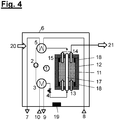
- Fig. 4 shows an embodiment in which an induced draft fan is dispensed with.
- the resulting overpressure ensures that gas can escape to the outside through the outlet opening 21. Since the leaked working fluid in the housing 6 is then completely separated in the activated carbon adsorber 12, the negative pressure that then arises in the housing 6 must be compensated for by opening the inlet opening 20.
Landscapes
- Engineering & Computer Science (AREA)
- Physics & Mathematics (AREA)
- Mechanical Engineering (AREA)
- Thermal Sciences (AREA)
- General Engineering & Computer Science (AREA)
- Solid-Sorbent Or Filter-Aiding Compositions (AREA)
- Separation Of Gases By Adsorption (AREA)
- Compressor (AREA)
Abstract
Description
- Die Erfindung betrifft irreguläre Zustände in Kältekreisen, in denen ein als Kältemittel wirkendes Arbeitsfluid in einem thermodynamischen Kreisprozess, wie zum Beispiel dem Clausius-Rankine-Kreisprozess, geführt wird, sowie deren adsorptive Sicherheitseinrichtung. Vorwiegend sind dies Wärmepumpen, Klimaanlagen und Kühlgeräte, wie sie in Wohngebäuden gebräuchlich sind. Unter Wohngebäuden werden dabei Privathäuser, Miethauskomplexe, Krankenhäuser, Hotelanlagen, Gastronomie und kombinierte Wohn- und Geschäftshäuser verstanden, in denen Menschen dauerhaft leben und arbeiten, im Unterschied zu mobilen Vorrichtungen wie KFZ-Klimaanlagen oder Transportboxen, oder auch Industrieanlagen oder medizintechnischen Geräten. Gemeinsam ist diesen Kreisprozessen, dass sie unter Einsatz von Energie Nutzwärme oder Nutzkälte erzeugen und Wärmeverschiebungssysteme bilden.
- Die zum Einsatz kommenden thermodynamischen Kreisprozesse sind seit langem bekannt, ebenso die Sicherheitsprobleme, die bei der Verwendung geeigneter Arbeitsfluide entstehen können. Abgesehen von Wasser sind die bekanntesten damaligen Arbeitsfluide brennbar und giftig. Sie führten im vergangenen Jahrhundert zur Entwicklung der Sicherheitskältemittel, die aus fluorierten Kohlenwasserstoffen bestanden. Es zeigte sich jedoch, dass diese Sicherheitskältemittel zur Klimaerwärmung führen und dass ihre sicherheitstechnische Unbedenklichkeit zu konstruktiven Unachtsamkeiten führte. Bis zu 70 % des Umsatzes entfiel auf den Nachfüllbedarf undichter Anlagen und deren Leckageverluste, der hingenommen wurde, solange dies im Einzelfall als wirtschaftlich vertretbar empfunden wurde und Bedarf an Ersatzbeschaffung förderte.
- Heutige Kältekreise sind ausgestattet mit diesen Sicherheitskältemitteln der Sicherheitsklasse A1, d.h. sie sind nicht giftig und nicht brennbar. Die gebräuchlichsten Kältemittel im Bereich der Wärmepumpenanwendungen sind die Kältemittel R134a, R407C bzw. R410A, allesamt Fluorkohlenwasserstoffverbindungen. Der Einsatz dieser Kältemittel war bis Januar 2015 keinerlei Restriktionen unterworfen, die Einführung der F-Gase- Verordnung (EU) 517/2014 zum 01. Januar 2015 schränkt zukünftig die Anwendung von Fluorkohlenwasserstoff- Kältemitteln über Mengenbegrenzungen in der Europäischen Union derartig ein, dass die Preise bisheriger Kältemittel deutlich ansteigen werden. Ziel der F-Gase-Verordnung ist die mittelfristige Verbannung der treibhausgasfördernden Kältemittel und den Ersatz durch natürliche Kältemittel bzw. gegen chemische Kältemittel mit erheblich reduziertem Treibhauspotenzial.
- Nachteilig ist jedoch, dass nahezu alle Kältemittelalternativen zur Gruppe der brennbaren Kältemittel gehören, insbesondere die technisch vielversprechendsten Kältemittel wie z.B. R290 (Propan) und R1270 (Propylen).
- Es ist daher einerseits äußerst problematisch, die konstruktiven Prinzipien für Kältemittel-führende thermodynamische Prozesse zu übernehmen, die sich bei Sicherheitskältemitteln scheinbar gut bewährt haben, andererseits auf die Anlagenkonzepte aus der Zeit vor Einführung der Sicherheitskältemittel aufzusetzen. Dies liegt auch daran, dass inzwischen aus Einzelgeräten komplexe Anlagen geworden sind, was die Anzahl der Möglichkeiten für Störungen und deren Folgen vervielfältigt hat.
- Die
DE 10 2011 116 863 A1 beschreibt ein Verfahren zur Sicherung einer Vorrichtung für einen thermodynamischen Kreisprozess, welche mit einem Prozessfluid betrieben wird, das mindesten eine umweltgefährliche, giftige und/oder entzündliche Substanz enthält oder daraus besteht. Im Falle einer Leckage in der Vorrichtung für einen thermodynamischen Kreisprozess ein Adsorptionsmittel mit dem Prozessfluid, insbesondere Ammoniak, Propan oder Propen, in Kontakt gebracht und die Substanz durch das Adsorptionsmittel selektiv gebunden. Das Adsorptionsmittel wird nach Gebrauch regeneriert. Als Adsorptionsmittel werden Zeolith, auch in Kombination mit Imidazol oder Phosphaten, ferner CuBTC vorgeschlagen, das Adsorptionsmittel kann in Form einer Schüttung, eines Formkörpers, eines Anstrichs, eines Sprühfilms oder einer Beschichtung ausgestattet sein. Die Trägerstruktur des Formkörpers kann aus Mikrostruktur, Lamellenstruktur, Rohrbündel, Rohrregister und Blech bestehen und muss mechanisch stabil sowie stark oberflächenvergrößernd sein. Eine Umwälzung der potenziell kontaminierten Luft erfolgt üblicherweise kontinuierlich, kann aber auch durch einen Sensor initiiert werden, der die Lüftung nach Erreichen eines Schwellenwerts oder bei einem erkannten Havariefall einschaltet. Die Adsorption kann innerhalb oder außerhalb eines geschlossenen Raumes durchgeführt werden. - Die
DE 195 25 064 C1 beschreibt eine Kältemaschine mit einem gasdicht ausgebildeten Gehäuse, welches alle kältemittelführenden Komponenten der Maschine aufnimmt, ein das Innere des gasdichten Gehäuses mit einem Auslass verbindender Raum vorgesehen ist, und der Raum mit einem das Kältemittel sorbierenden Stoff gefüllt ist. Die Menge des sorbierenden Stoffes wird dabei so dimensioniert, dass die gesamte Menge an eventuell austretendem Kältemittel aufgenommen und von der Umwelt ferngehalten werden kann. Der mit dem sorbierenden Stoff gefüllte Raum ist zur Umgebung hin offen. Bei Kältemitteln, die schwerer als Luft sind, ist der Raum nach unten hin offen, bei solchen, die leichter sind, ist er nach oben hin offen, so dass ein Fördergebläse nicht erforderlich ist. Das Sorptionsmittel wird in das Gehäuse eingebracht und umschließt die Kältemaschine bzw. die kältemittelführenden Einrichtungen vollständig. Auf seinem Weg nach außen sind Schikanen vorgesehen, die Kurzschlussströmungen verhindern und entweichendes Gas durch das Sorptionsmittel zwingen. Auch eine doppelwandige Ausführungsform, bei der das Sorptionsmittel im Doppelmantel angeordnet ist, ist möglich. Am Ausgang des mit dem sorbierenden Stoffes gefüllten Raumes zur Umgebung hin kann eine Messeinrichtung für Kältemittel vorgesehen werden. - Die
EP 3 106 780 A1 beschreibt eine Wärmepumpenanlage, die in einem mit einem Bindemittel ausgekleideten, luftdichten Gehäuse untergebracht ist. Innerhalb dieses Gehäuses kann eine Adsorptionseinheit mit einer Zwangslüftung angeordnet sein, die im Umluftbetrieb die Luft im Gehäuse reinigt. Dieser Umluftbetrieb kann kontinuierlich oder nur im Störfall oder in regelmäßigen Intervallen erfolgen. Stromab dieser Sorptionsstufe kann auch ein Zündbrenner, eine Pilotflamme, ein katalytischer Brenner oder ein Heizdraht angeordnet sein, der ggf. restliche brennbare Verunreinigungen verbrennt. Ebenfalls denkbar ist eine Frischluftzufuhr in Verbindung mit der Ableitung gereinigter Abluft. - Die
JP 2000 105003 A - Problematisch ist beim Einsatz von Aktivkohle als Adsorbens, dass Aktivkohle mit der Zeit an der Luft altert, weil langsame Oxidationsvorgänge stattfinden. Aufgrund der Anforderungen eines Sicherheitskonzeptes an die Verfügbarkeit über die Lebensdauer von Geräten, in denen linksdrehende Kreisprozesse betrieben werden, wie zum Beispiel Wärmepumpen, muss eine Degradation des Adsorptionsmittels aber unbedingt vermieden werden, vor allem wenn sie unbemerkt geschehen könnte.
- Je nach Bauart, Aufstellungsort und Betriebsweise beispielsweise einer Wärmepumpe ergeben sich unterschiedliche Anforderungen an eine mögliche Belastung des Adsorptionsmittels durch Co-Adsorbenzien, also etwa VOC, Wasserdampf aus Luftfeuchte, Luftsauerstoff, Temperaturwechseln, und anderen. Zu unterscheiden ist dabei zwischen Auskleidungen und durchströmten Sorptionsbetten. Bei den durchströmten Sorptionsbetten ist zu unterscheiden zwischen solchen, die innerhalb eines Gehäuses im Umluftbetrieb sind und solchen, die nach außen hin entlüften. Die Erfindung betrifft hierbei erstere, wobei jedoch auch Kombinationen mit den davor erwähnten umluftbetriebenen Sorptionsbetten und Auskleidungen einsetzbar sind.
- Es wird im Folgenden zwar angenommen, dass sich das Sorptionsbett in einem Kanal mit einer Einströmseite und einer Ausströmseite innerhalb des Gehäuses befindet, in dem auch der linksdrehende Kreisprozess durchgeführt wird. Statt eines langgestreckten, linearen Sorptionskanals können aber auch andere Bauformen von Sorptionskanälen zur Anwendung kommen und die Aggregate des durchgeführten Kreisprozesses können auch in einem separaten Kapselgehäuse angeordnet sein, welches sich innerhalb des gemeinsamen Gehäuses mit dem Sorptionskanal befindet, und sind ebenfalls von der Erfindung umfasst, ebenso solche, bei denen der Sorptionsvorgang außerhalb des Gehäuses stattfindet..
- Die Belastung solcher in Bezug auf das Gehäuse nach innen und nach außen offenen Sorptionsbetten durch Kontamination wird durch Diffusion und Konvektion von Kontaminaten, im Falle der Adsorption vom konterminierenden Adsorptiv verursacht. Die Kontaminaten können dabei reversible oder auch irreversible Degradationen der Sorptionskapazität des Sorptionsbettes gegenüber dem austretenden Arbeitsfluid verursachen. Die Diffusionsströmung wird dabei einzig durch das Konzentrationsgefälle angetrieben, während konvektive Einträge durch wetterinduzierte Luftdruck- oder auch Temperaturgradienten zwischen Gehäuse und Umgebung verursacht werden. Die resultierenden Druckunterschiede führen zu Ausgleichsströmungen in das Gehäuse und damit auch durch das Sorptionsbett und zum Stofftransport von Kontaminaten in das Sorptionsbett.
- Aus dem Gehäuse, in dem der Kreisprozess durchgeführt wird, kommen als Kontaminaten Sauerstoff, ein- und mehrwertige Alkohole, Feuchte, Ziehfette, Schneidöle, Schäummittel und RCM-Öle in Betracht. Im Falle von Aktivkohle als Adsorbensmaterial ist die Alterung bzw. Degradation von der Temperatur und der insgesamt durchströmten Gasmenge bestimmt.
- Die Aufgabe der Erfindung ist daher, eine sichere Vorrichtung zur Verfügung zu stellen, die die beschriebenen Nachteile nicht mehr aufweist und deren Degradation des Aktivkohleadsorbers minimal wird. Die Erfindung löst die Aufgabe durch eine Vorrichtung zur sicheren Durchführung eines linksdrehenden thermodynamischen Kreisprozesses mittels eines entzündlichen Arbeitsfluids, welches in einem geschlossenen, hermetisch dichten Arbeitsfluidumlauf geführt wird, aufweisend
- mindestens einen Verdichter für Arbeitsfluid,
- mindestens eine Entspannungseinrichtung für Arbeitsfluid,
- mindestens zwei Wärmeübertrager für Arbeitsfluid mit jeweils mindestens zwei Anschlüssen für Wärmeüberträgerfluide,
- ein Gehäuse, welches wenigstens den Verdichter und die Entspannungseinrichtung für Arbeitsfluid umfasst und weitere Einrichtungen umfassen kann,
- mindestens einen Sorptionskanal mit einem Aktivkohle enthaltenden Adsorber, der von Gas durchströmt werden kann
- und der Sorptionskanal mit dem Adsorber sowie seinem Gaseinlass verbunden ist, wobei
- der Sorptionskanal gegenüber dem Inneren des Gehäuses durch eine thermische Dämmung begrenzt wird,
- der Sorptionskanal am Gaseinlass verschließbar ist, und
- im Sorptionskanal mindestens eine Kühlleitung verlegt ist, die an ein Kühlmedium angeschlossen ist.
- In einer Ausgestaltung ist vorgesehen, dass der Sorptionskanal mit einem Gasauslass ausgestattet und mit ihm verbunden ist. Ferner kann vorgesehen werden, dass am Gasauslass des Sorptionskanals ein schaltbares Saugzuggebläse angeschlossen ist.
- In einer Ausgestaltung sind der Adsorber, der Sorptionskanal sowie Gaseinlass und Gasauslass innerhalb des Gehäuses angeordnet. Es ist jedoch auch möglich, diese außerhalb des Gehäuses anzuordnen oder ebenso wie die Wärmeübertrager Verdampfer und Kondensator in die Gehäusewand zu integrieren.
- Im Normalfall sind Gaseinlass und Gasauslass des Sorptionskanals mit dem Aktivkohleadsorber verschlossen. Die Aktivkohle wird durch das Kühlmedium auf einer sehr niedrigen Temperatur gehalten, die deutlich unter der Innenraumtemperatur des Gehäuses liegt. Diese Temperaturabsenkung hat zwei Wirkungen: Einerseits verlangsamen sich die Alterung und die Degradation, andererseits erhöht sich die Aufnahmekapazität der Aktivkohle. Dazu muss der Adsorber aber dauerhaft kühlgehalten werden, weshalb eine gute Wärmedämmung erforderlich ist.
- In einer Ausgestaltung der Erfindung verfügt die Vorrichtung über ein Leckageerkennungssystem, welches die Verschlüsse am Gaseinlass und, sofern vorhanden, am Gasauslass automatisch öffnet und das Saugzuggebläse, sofern vorhanden, automatisch einschaltet, wenn eine Leckage erkannt wird. Das Leckageerkennungssystem ist üblicherweise ein Gasdetektor, wobei ein Propangasmelder zum Einsatz kommen kann, andere Erkennungssysteme sind jedoch ebenfalls geeignet. Für den Fall eines Stromausfalls sollte das Saugzuggebläse über einen stets geladenen Akku verfügen.
- Weitere Ansprüche betreffen das Kühlmedium. Es ist zwar problemlos möglich, ein extern vorhandenes Kühlmedium zu verwenden, wenn dies günstig zur Verfügung steht, aber es können auch zwei Möglichkeiten genutzt werden, Kühlmedien zu nutzen, die als Arbeitsfluide im Kreisprozess verwendet werden. So kann alternativ vorgesehen werden dass entweder das Kühlmedium entspanntes Arbeitsfluid ist, welches in Strömungsrichtung nach der Entspannungsvorrichtung und vor dem als Verdampfer wirkenden Wärmeübertrager, strömt, oder dass das Kühlmedium entspanntes Arbeitsfluid ist, welches in Strömungsrichtung nach dem als Verdampfer wirkenden Wärmeübertrager zum Verdichter strömt.
- Im Normalbetrieb muss hierbei nur der Wärmeverlust, der trotz der thermischen Dämmung auftritt, ausgeglichen werden, was nur einen geringen Verlust bedeutet. Sofern der Kreisprozess eine Wärmepumpe ist, welche die Energie aus dem Verdampfer bezieht, bedeutet die Nutzung als Kühlmedium sogar eine Verbesserung der Wärmeausbeute. Ansonsten kann es bei sehr geringen, auszugleichenden Wärmeeinträgen durch die thermische Dämmung auch sinnvoll sein, nur einen kleinen Teilstrom des Arbeitsfluids durch die Kühlleitungen hindurchzuleiten.
- Die Kühlleitungen sind im Kühlkanal so zu verlegen, dass das Adsorbensmaterial zugänglich bleibt, um es gegebenenfalls entnehmen und austauschen zu können. Gleichzeitig sollte aber genügend Wärmeübertragungsfläche installiert werden. Dies kann dadurch geschehen, dass man eine Kühlleitung mittig im Sorptionskanal verlegt und diese mit Kühlrippen in Längsrichtung ausstattet. Die Abstände der Kühlrippen sollten größer sein als die Partikel der Aktivkohle, sofern eine Aktivkohleschüttung als Adsorbens zum Einsatz kommt.
- Oft werden linksdrehende Kreisprozesse nicht das ganze Jahr über kontinuierlich betrieben. Nach längeren Stillständen kann es daher sein, dass längere Zeit kein Kühlmedium durch die Kühlleitungen geflossen ist und der Aktivkohleadsorber warm geworden ist. Da solche Wiederanfahrvorgänge gleichzeitig die Betriebszustände sind, bei denen das höchste Leckagerisiko besteht, ist es sinnvoll, den Adsorber stets gekühlt zu halten. Diese Kühlhaltung kann durch Peltier-Elemente erfolgen, deren Aufgabe es ist, während der Stillstandszeiten den Temperaturausgleich durch die thermische Dämmung zu kompensieren.
- Weiterhin können Latentwärmespeicher zur Verlangsamung eines solchen stillstandsbedingten Temperaturausgleichs eingesetzt werden. Dies kann entweder als zusätzliche Schicht an der thermischen Dämmung oder in Form von Pellets, die in die Aktivkohleschüttung hinzugemischt werden, erfolgen. Als Materialien können Salze, die Phasenänderungen im relevanten Temperaturbereich durchführen, dienen, wobei sie mit Schutzhüllen zu versehen sind. Derartige Materialien sind im Stand der Technik beschrieben.
- Da der Aktivkohleadsorber während des Normalbetriebs verschlossen ist, kann er zuvor mit einem Medium vorbeladen werden, welches eine geringere adsorptive Bindung als das entzündliche Arbeitsfluid, welches im Leckagefall abzuscheiden ist, aufweist. Während der Adsorption des Arbeitsfluids bewirkt die Adsorptionswärme eine Erwärmung des Aktivkohleadsorbers, was unerwünscht ist. Dagegen bewirkt die Desorption des verdrängten Mediums eine Abkühlung. Das zu verdrängende Medium kann dabei schon vorher unter hohem Partialdruck adsorbiert werden, wobei die typischen Hystereseverläufe bewirken, dass bei reduziertem Partialdruck zunächst keine vollständige Desorption erfolgt. Diese Überladung mit einem zu verdrängenden Medium kann also dazu führen, dass die Wärmetönung durch die Adsorption vollständig kompensiert wird, obwohl die geringere adsorptive Bindung des Mediums tendenziell auch weniger Bindungsenergie verbraucht. Die höhere Menge an desorbiertem Medium gleicht dies aus. Als bevorzugte Medien werden Stickstoff und Kohlendioxid verwendet, deren Desorption in das Gehäuse verringert darüber hinaus die Entzündungsgefahr im Fall einer Leckage.
- In bevorzugten Ausführungsformen ist daher vorgesehen, dass
- das Adsorbens mit einem Adsorbat vorbeladen ist, welches vom Adsorptiv verdrängt wird und dabei das Adsorbens kühlt,
- das Adsorbat, mit dem das Adsorbens vorbeladen ist, Stickstoff oder Kohlendioxid ist,
- das Adsorbens, welches mit dem Adsorbat vorbeladen ist, Aktivkohle ist,
- das Adsorptiv, welches das Adsorbat verdrängt, das Kältemittel R290 ist.
- Das Gehäuse kann entweder geschlossen oder mit Öffnungen ausgeführt sein. Wenn das Gas innerhalb des Gehäuses bleiben soll, ist entweder ein Zwangsumlauf vorzusehen, der von einem Fördergebläse betrieben wird, oder die Adsorption des ausgetretenen Arbeitsfluids findet allein durch Diffusion statt. Falls das Austreten des von Arbeitsfluid abgereichertem oder ganz befreitem Gas zugelassen werden kann, kann entweder ein Fördergebläse das Gas aus dem Sorptionskanal absaugen und über eine Auslassöffnung nach außen befördern, wobei gleichzeitig durch eine Öffnung ein gleich großer Luftstrom von außen nachgeführt werden muss, oder der bei der Leckage möglicherweise entstehende Überdruck im Gehäuse treibt das Gas durch den Sorptionskanal aus der Auslassöffnung nach außen.
- Sobald jedoch nach erfolgtem Druckausgleich das restliche Arbeitsfluid in den Sorptionskanal diffundiert, würde ein Unterdruck entstehen, der ausgeglichen werden muss. Würde man hier eine Rückströmung durch die Auslassöffnung und den damit verbundenen Sorptionskanal zulassen, müsste auch mit einer Teildesorption gerechnet werden, was unerwünscht ist. Aus diesem Grund wird eine separate Einlassöffnung ins Gehäuse vorgesehen, die als Unterdrucksicherung ausgeführt wird.
- Die Erfindung wird nachfolgend anhand von vier Prinzipskizzen näher erläutert. Hierbei zeigen:
- Figur 1:
- eine Wärmepumpe mit einem Sorptionskanal und Zwangsumluft,
- Figur 2:
- eine Wärmepumpe mit einem Sorptionskanal und Lufteinleitung,
- Figur 3:
- eine Wärmepumpe mit einem Sorptionskanal und Zwangsspülung,
- Figur 4:
- eine Wärmepumpe mit einem Sorptionskanal und passiver Spülung.
-
Fig. 1 zeigt eine Wärmepumpe mit gekühltem Adsorber und Zwangsumlauf anhand einer Prinzipskizze eines Kältekreises 1 mit einem Verdichter 2, einem Kondensator 3, einer Druckreduzierung 4 und einem Verdampfer 5 in einem Gehäuse 6. Die Wärmepumpe verfügt über einen Wärmequellen-Anschluss 7, einen Wärmequellen-Vorlauf 8, einen Wärmesenken-Vorlauf 9 und einen Wärmesenken-Anschluss 10. - Weiterhin ist im Gehäuse der Sorptionskanal 11 mit dem Aktivkohleadsorber 12 angeordnet. Der Sorptionskanal 11 ist mit der Kühlleitung 17 ausgestattet, ferner optional mit den Peltier-Elementen 19 und Latentwärmespeicherpellets. Die Kühlleitung 17 ist eingebunden in den Kreisprozess, das Kühlmedium ist gleichzeitig das Arbeitsfluid. Es wird hinter der Entspannungsvorrichtung 4, die üblicherweise ein geregeltes Entspannungsventil ist, abgegriffen und durch die Kühlleitung 17 wieder zurück in den Kältekreis 1 geführt, wo es in den Verdampfer 5 gelangt. Weiterhin ist der Sorptionskanal nach allen Seiten thermisch gedämmt, wobei auf die thermische Dämmung 15 großer Wert gelegt wird.
- Der Kältekreis 1 wird in diesem Beispiel mit dem entzündlichen Arbeitsfluid Propan, welches auch unter der Bezeichnung R290 bekannt ist, betrieben. Propan ist schwerer als Luft, daher sinkt es im Falle einer Leckage im Kältekreis 1 tendenziell im Gehäuse 6 nach unten, wenngleich es sich bei kleinen Leckagen gut vermischt. Eine solche Leckage wird durch den Gasdetektor 18 erkannt. Im unteren Bereich des Gehäuses 6 ist daher eine Öffnung mit einem absperrbaren Gaseinlass 13 vorgesehen, durch die ein Luft-Propangemisch aus dem Innenraum in den Sorptionskanal 11 mit dem Aktivkohleadsorber 12 gelangt, wenn Gaseinlass 13 und Gasauslass 14 auf Veranlassung des Gasdetektors 18 geöffnet werden.
- In einem solchen Fall zieht das ebenfalls von Gasdetektor 18 automatisch aktivierte Saugzugsgebläse 16 eine definierte Menge Gas durch den Aktivkohleadsorber, wobei gereinigte Luft, gegebenenfalls angereichert mit den Inertgasen Stickstoff und Kohlendioxid, in das Gehäuse zurückgeführt werden. Wenn möglich wird dabei der Kältekreis 1 noch etwas weiterbetrieben, um die Kühlleistung für den Aktivkohleadsorber 12 sicherzustellen. Sobald der Aktivkohleadsorber beladen ist, werden Gaseinlass 13 und Gasauslass 14 wieder geschlossen und das Saugzuggebläse 16 wird ebenso wie die übrige Wärmepumpe abgeschaltet und der Service wird gerufen.
-
Fig. 2 zeigt ein Ausführungsbeispiel, bei dem auf den Zwangsumlauf verzichtet wird. Im Leckagefall diffundieren die entzündlichen Gasbestandteile durch die Gaseinlässe 13, die sich in diesem Beispiel sowohl an der Oberseite als auch an der Unterseite des Sorptionskanals 11 befinden, in den Aktivkohleadsorber 12. -
Fig. 3 zeigt ein Ausführungsbeispiel, bei dem ein Saugzuggebläse 16 das beladene Gas, wie inFig. 1 dargestellt, das Gas durch den Sorptionskanal 11 zieht, sobald eine Leckage erkannt ist. Abweichend davon wird das Gas jedoch nicht im Umlauf innerhalb des Gehäuses 6 geführt, sondern nach außen über die Auslassöffnung 21 geleitet. Eine dem entsprechende Luftmenge wird durch die Einlassöffnung 20 von außen nachgeführt. -
Fig. 4 zeigt ein Ausführungsbeispiel, bei dem auf ein Saugzuggebläse verzichtet wird. Im Falle einer Leckage bewirkt der dadurch entstehende Überdruck, dass Gas nach außen durch die Auslassöffnung 21 entweichen kann. Da das ausgetretene Arbeitsfluid im Gehäuse 6 nachfolgend vollständig im Aktivkohleadsorber 12 abgeschieden wird, muss der dann entstehende Unterdruck im Gehäuse 6 durch Öffnen der Einlassöffnung 20 ausgeglichen werden. -
- 1
- Kältekreis
- 2
- Verdichter
- 3
- Kondensator
- 4
- Druckreduzierung
- 5
- Verdampfer
- 6
- Gehäuse
- 7
- Wärmequellen-Anschluss
- 8
- Wärmequellen-Vorlauf
- 9
- Wärmesenken-Vorlauf
- 10
- Wärmesenken-Anschluss
- 11
- Sorptionskanal
- 12
- Aktivkohleadsorber
- 13
- Gaseinlass
- 14
- Gasauslass
- 15
- Thermische Dämmung
- 16
- Saugzuggebläse
- 17
- Kühlleitung
- 18
- Gasdetektor
- 19
- Peltier-Element
- 20
- Einlassöffnung
- 21
- Auslassöffnung
Claims (20)
- Vorrichtung zur sicheren Durchführung eines linksdrehenden thermodynamischen Kreisprozesses (1) mittels eines entzündlichen Arbeitsfluids, welches in einem geschlossenen, hermetisch dichten Arbeitsfluidumlauf geführt wird, aufweisend- mindestens einen Verdichter (2) für Arbeitsfluid,- mindestens eine Entspannungseinrichtung (4) für Arbeitsfluid,- mindestens zwei Wärmeübertrager (3, 5) für Arbeitsfluid mit jeweils mindestens zwei Anschlüssen (7, 8, 9, 10) für Wärmeüberträgerfluide,- ein Gehäuse (6), welches wenigstens den Verdichter (2) und die Entspannungseinrichtung (4) umfasst und weitere Einrichtungen umfassen kann,- mindestens einen Sorptionskanal (11) mit einem Aktivkohle enthaltenden Adsorber (12), der von Gas durchströmt werden kann- und der Sorptionskanal (11) mit dem Adsorber (12) sowie seinem Gaseinlass (13) verbunden ist,dadurch gekennzeichnet, dass- der Sorptionskanal (11) gegenüber seinem Äußeren durch eine thermische Dämmung (15) begrenzt wird,- der Sorptionskanal (11) am Gaseinlass (13) verschließbar ist, und- im Sorptionskanal (11) mindestens eine Kühlleitung (17) verlegt ist, die an ein Kühlmedium angeschlossen ist.
- Vorrichtung nach Anspruch 1, dadurch gekennzeichnet, dass der Sorptionskanal (11) mit einem Gasauslass (14) ausgestattet ist und mit ihm verbunden ist.
- Vorrichtung nach Anspruch 2, dadurch gekennzeichnet, dass am Gasauslass (14) des Sorptionskanals (11) ein schaltbares Saugzuggebläse (16) angeschlossen ist.
- Vorrichtung nach einem der Ansprüche 2 oder 3, dadurch gekennzeichnet, dass der Adsorber (12), der Sorptionskanal (11) sowie Gaseinlass (13) und Gasauslass (14) innerhalb des Gehäuses (6) angeordnet sind.
- Vorrichtung nach Anspruch 1, dadurch gekennzeichnet, dass im Gehäuse ein Leckageerkennungssystem (18) vorgesehen ist, welches den Verschluss am Gaseinlass (13) öffnet.
- Vorrichtung nach einem der Ansprüche 3 bis 5, dadurch gekennzeichnet, dass beim Öffnen des Verschlusses am Gaseinlass (13) auch der Verschluss am Gasauslass (14) öffnet und das Saugzuggebläse (16) einschaltet wird, wenn eine Leckage erkannt wird.
- Vorrichtung nach Anspruch 5, dadurch gekennzeichnet, dass das Leckageerkennungssystem (18) ein Gasdetektor für entzündliches Gas, insbesondere Propan, ist.
- Vorrichtung nach einem der Ansprüche 1 bis 7, dadurch gekennzeichnet, dass das Kühlmedium entspanntes Arbeitsfluid ist, welches in Strömungsrichtung nach der Entspannungsvorrichtung (4) und vor dem als Verdampfer wirkenden Wärmeübertrager (5), strömt.
- Vorrichtung nach einem der Ansprüche 1 bis 7, dadurch gekennzeichnet, dass das Kühlmedium entspanntes Arbeitsfluid ist, welches in Strömungsrichtung nach dem als Verdampfer wirkenden Wärmeübertrager (5) zum Verdichter (2) strömt.
- Vorrichtung nach einem der Ansprüche 8 oder 9, dadurch gekennzeichnet, dass ein Teilstrom des Arbeitsfluids als Kühlmedium genutzt wird.
- Vorrichtung nach einem der Ansprüche 8 oder 9, dadurch gekennzeichnet, dass das gesamte Arbeitsfluid als Kühlmedium genutzt wird.
- Vorrichtung nach einem der Ansprüche 1 bis 11, dadurch gekennzeichnet, dass die mindestens eine Kühlleitung (17) in Längsrichtung Kühlrippen aufweist.
- Vorrichtung nach einem der Ansprüche 1 bis 12, dadurch gekennzeichnet, dass zusätzlich Peltier-Elemente (19) zur Kühlung oder Kühlhaltung eingesetzt werden.
- Vorrichtung nach einem der Ansprüche 1 bis 13, dadurch gekennzeichnet, dass zusätzlich Latentwärmespeicher zur Kühlhaltung im Sorptionskanal vorgesehen werden.
- Vorrichtung nach einem der Ansprüche 1 bis 14, dadurch gekennzeichnet, dass das Adsorbens mit einem Adsorbat vorbeladen ist, welches vom Adsorptiv verdrängt wird und dabei das Adsorbens kühlt.
- Vorrichtung nach Anspruch 15, dadurch gekennzeichnet, dass das Adsorbat, mit dem das Adsorbens vorbeladen ist, Stickstoff oder Kohlendioxid ist.
- Vorrichtung nach Anspruch 15, dadurch gekennzeichnet, dass das Adsorbens, welches mit dem Adsorbat vorbeladen ist, Aktivkohle ist.
- Vorrichtung nach Anspruch 15, dadurch gekennzeichnet, dass das Adsorptiv, welches das Adsorbat verdrängt, das Kältemittel R290 ist.
- Vorrichtung nach einem der Ansprüche 1 bis 18, dadurch gekennzeichnet, dass das Gehäuse mit einer Einlassöffnung (20) und einer Auslassöffnung (21) verbunden ist.
- Vorrichtung nach Anspruch 19, dadurch gekennzeichnet, dass die Auslassöffnung (21) mit einem Fördergebläse (16) verbunden ist.
Applications Claiming Priority (2)
| Application Number | Priority Date | Filing Date | Title |
|---|---|---|---|
| DE102019102925 | 2019-02-06 | ||
| DE102019118977.2A DE102019118977A1 (de) | 2019-02-06 | 2019-07-12 | Adsorberkühlung |
Publications (4)
| Publication Number | Publication Date |
|---|---|
| EP3693687A2 true EP3693687A2 (de) | 2020-08-12 |
| EP3693687A3 EP3693687A3 (de) | 2020-10-21 |
| EP3693687B1 EP3693687B1 (de) | 2024-03-06 |
| EP3693687C0 EP3693687C0 (de) | 2024-03-06 |
Family
ID=69172703
Family Applications (1)
| Application Number | Title | Priority Date | Filing Date |
|---|---|---|---|
| EP20151979.0A Active EP3693687B1 (de) | 2019-02-06 | 2020-01-15 | Adsorberkühlung |
Country Status (1)
| Country | Link |
|---|---|
| EP (1) | EP3693687B1 (de) |
Cited By (6)
| Publication number | Priority date | Publication date | Assignee | Title |
|---|---|---|---|---|
| EP4086540A1 (de) * | 2021-05-06 | 2022-11-09 | Vaillant GmbH | Adsorber-regeneration mit voc-abreicherung |
| EP4209728A1 (de) | 2022-01-07 | 2023-07-12 | Vaillant GmbH | Wärmepumpe mit adsorber und katalysator |
| US11971183B2 (en) | 2019-09-05 | 2024-04-30 | Trane International Inc. | Systems and methods for refrigerant leak detection in a climate control system |
| US12117191B2 (en) | 2022-06-24 | 2024-10-15 | Trane International Inc. | Climate control system with improved leak detector |
| EP4474735A1 (de) * | 2023-06-06 | 2024-12-11 | Vaillant GmbH | System bestehend aus mindestens zwei vorrichtungen zur sicherung eines kältekreises und assoziiertes gaspendelverfahren |
| US12487008B2 (en) | 2022-01-14 | 2025-12-02 | Trane International Inc. | Method of commissioning an HVAC system |
Citations (4)
| Publication number | Priority date | Publication date | Assignee | Title |
|---|---|---|---|---|
| DE19525064C1 (de) | 1995-07-10 | 1996-08-01 | Joachim Dr Ing Paul | Kältemaschine |
| JP2000105003A (ja) | 1998-09-28 | 2000-04-11 | Sanyo Electric Co Ltd | 冷凍機ユニット |
| DE102011116863A1 (de) | 2011-10-25 | 2013-04-25 | Fraunhofer-Gesellschaft zur Förderung der angewandten Forschung e.V. | Verfahren zur Sicherung einer Vorrichtung für einen thermodynamischen Kreisprozess und abgesicherte Vorrichtung für einen thermodynamischen Kreisprozess |
| EP3106780A1 (de) | 2015-06-17 | 2016-12-21 | Vaillant GmbH | Wärmepumpenanlage |
Family Cites Families (4)
| Publication number | Priority date | Publication date | Assignee | Title |
|---|---|---|---|---|
| US5165247A (en) * | 1991-02-11 | 1992-11-24 | Rocky Research | Refrigerant recycling system |
| DE4114529A1 (de) * | 1991-05-03 | 1993-02-11 | Aero Tech Klima Kaelte | Sicherheitseinrichtung fuer eine kaeltetechnische anlage |
| CN1153032C (zh) * | 1998-06-11 | 2004-06-09 | 三洋电机株式会社 | 致冷剂再生装置 |
| JP3149871B2 (ja) * | 1999-07-05 | 2001-03-26 | 松下電器産業株式会社 | 置換用気体の回収トラップ容器及び空気調和機の施工方法 |
-
2020
- 2020-01-15 EP EP20151979.0A patent/EP3693687B1/de active Active
Patent Citations (4)
| Publication number | Priority date | Publication date | Assignee | Title |
|---|---|---|---|---|
| DE19525064C1 (de) | 1995-07-10 | 1996-08-01 | Joachim Dr Ing Paul | Kältemaschine |
| JP2000105003A (ja) | 1998-09-28 | 2000-04-11 | Sanyo Electric Co Ltd | 冷凍機ユニット |
| DE102011116863A1 (de) | 2011-10-25 | 2013-04-25 | Fraunhofer-Gesellschaft zur Förderung der angewandten Forschung e.V. | Verfahren zur Sicherung einer Vorrichtung für einen thermodynamischen Kreisprozess und abgesicherte Vorrichtung für einen thermodynamischen Kreisprozess |
| EP3106780A1 (de) | 2015-06-17 | 2016-12-21 | Vaillant GmbH | Wärmepumpenanlage |
Cited By (7)
| Publication number | Priority date | Publication date | Assignee | Title |
|---|---|---|---|---|
| US11971183B2 (en) | 2019-09-05 | 2024-04-30 | Trane International Inc. | Systems and methods for refrigerant leak detection in a climate control system |
| EP4086540A1 (de) * | 2021-05-06 | 2022-11-09 | Vaillant GmbH | Adsorber-regeneration mit voc-abreicherung |
| EP4209728A1 (de) | 2022-01-07 | 2023-07-12 | Vaillant GmbH | Wärmepumpe mit adsorber und katalysator |
| DE102022100269A1 (de) | 2022-01-07 | 2023-07-13 | Vaillant Gmbh | Katalytische Abluftbehandlung für eine Wärmepumpe |
| US12487008B2 (en) | 2022-01-14 | 2025-12-02 | Trane International Inc. | Method of commissioning an HVAC system |
| US12117191B2 (en) | 2022-06-24 | 2024-10-15 | Trane International Inc. | Climate control system with improved leak detector |
| EP4474735A1 (de) * | 2023-06-06 | 2024-12-11 | Vaillant GmbH | System bestehend aus mindestens zwei vorrichtungen zur sicherung eines kältekreises und assoziiertes gaspendelverfahren |
Also Published As
| Publication number | Publication date |
|---|---|
| EP3693687A3 (de) | 2020-10-21 |
| EP3693687B1 (de) | 2024-03-06 |
| EP3693687C0 (de) | 2024-03-06 |
Similar Documents
| Publication | Publication Date | Title |
|---|---|---|
| EP3693687B1 (de) | Adsorberkühlung | |
| EP3693683B1 (de) | Diffusionssperre mittels schutzschichten | |
| EP3581861B1 (de) | Fluidsorption | |
| EP4008979B1 (de) | Vorrichtung zur sicheren durchführung eines linksdrehenden thermodynamischen kreisprozesses | |
| EP3578895B1 (de) | Vorrichtung und verfahren für eine sichere und energiesparende spülung eines gehäuses | |
| EP1162415B1 (de) | Sorptionsvorrichtung zum Heizen und Kühlen von Gasströmen | |
| DE102009029392A1 (de) | Explosionsgeschützte Kälteanlage mit brennbarem Kältemittel | |
| EP3486582A1 (de) | Leckageerkennung mittels adsorber | |
| EP3792572A1 (de) | Sicherheitsspülvorrichtung für eine wärmepumpe | |
| DE102011116863A1 (de) | Verfahren zur Sicherung einer Vorrichtung für einen thermodynamischen Kreisprozess und abgesicherte Vorrichtung für einen thermodynamischen Kreisprozess | |
| DE102019118984A1 (de) | Diffusionssperre mittels Schutzschichten | |
| DE102019114744A1 (de) | Fluidadsorption | |
| EP3705823B1 (de) | Vorrichtung für einen sicheren serviceeingriff für ein gehäuse und verfahren zur öffnung eines gehäuses. | |
| EP3486564B1 (de) | VORRICHTUNG ZUR SICHEREN DURCHFÜHRUNG EINES LINKSDREHENDEN THERMODYNAMISCHEN CLAUSIUS-RANKINE PROZESS
BASIEREND AUF ARBEITSFLUIDADSORPTION MIT INERTGASVERDRÄNGUNG | |
| EP4086540A1 (de) | Adsorber-regeneration mit voc-abreicherung | |
| DE102019114738A1 (de) | Fluidadsorption | |
| DE102019118977A1 (de) | Adsorberkühlung | |
| EP4575332A1 (de) | Gekapselter adapter für eine split-wärmepumpe | |
| EP4462034A1 (de) | Zweistufig adsorptiv wirksames sicherheitskonzept | |
| EP4382193A1 (de) | Adsorptionsvorrichtung | |
| EP2637883A2 (de) | Abgas angetriebene adsorptionskältemaschine | |
| EP3492846B1 (de) | Vorrichtung zur sicheren durchführung eines linksdrehenden thermodynamischen clausius-rankine-kreisprozesses sowie seiner sicheren entleerung und befüllung mittels eines entzündlichen arbeitsfluids und ein verfahren zur sicheren entleeren eines entzündlichen arbeitsfluids | |
| DE102022100735A1 (de) | Katalytische Ausrüstungen von Adsorptionsmitteln | |
| DE102016106091A1 (de) | Klimaanlage mit Vakuumeinschluss | |
| DE102018127205A1 (de) | Sicherheitszone im Kondensator |
Legal Events
| Date | Code | Title | Description |
|---|---|---|---|
| PUAI | Public reference made under article 153(3) epc to a published international application that has entered the european phase |
Free format text: ORIGINAL CODE: 0009012 |
|
| STAA | Information on the status of an ep patent application or granted ep patent |
Free format text: STATUS: THE APPLICATION HAS BEEN PUBLISHED |
|
| AK | Designated contracting states |
Kind code of ref document: A2 Designated state(s): AL AT BE BG CH CY CZ DE DK EE ES FI FR GB GR HR HU IE IS IT LI LT LU LV MC MK MT NL NO PL PT RO RS SE SI SK SM TR |
|
| AX | Request for extension of the european patent |
Extension state: BA ME |
|
| PUAL | Search report despatched |
Free format text: ORIGINAL CODE: 0009013 |
|
| AK | Designated contracting states |
Kind code of ref document: A3 Designated state(s): AL AT BE BG CH CY CZ DE DK EE ES FI FR GB GR HR HU IE IS IT LI LT LU LV MC MK MT NL NO PL PT RO RS SE SI SK SM TR |
|
| AX | Request for extension of the european patent |
Extension state: BA ME |
|
| RIC1 | Information provided on ipc code assigned before grant |
Ipc: F25B 49/00 20060101AFI20200915BHEP Ipc: F25B 25/00 20060101ALI20200915BHEP Ipc: F25B 45/00 20060101ALI20200915BHEP |
|
| STAA | Information on the status of an ep patent application or granted ep patent |
Free format text: STATUS: REQUEST FOR EXAMINATION WAS MADE |
|
| 17P | Request for examination filed |
Effective date: 20210408 |
|
| RBV | Designated contracting states (corrected) |
Designated state(s): AL AT BE BG CH CY CZ DE DK EE ES FI FR GB GR HR HU IE IS IT LI LT LU LV MC MK MT NL NO PL PT RO RS SE SI SK SM TR |
|
| GRAP | Despatch of communication of intention to grant a patent |
Free format text: ORIGINAL CODE: EPIDOSNIGR1 |
|
| STAA | Information on the status of an ep patent application or granted ep patent |
Free format text: STATUS: GRANT OF PATENT IS INTENDED |
|
| INTG | Intention to grant announced |
Effective date: 20230927 |
|
| GRAS | Grant fee paid |
Free format text: ORIGINAL CODE: EPIDOSNIGR3 |
|
| GRAA | (expected) grant |
Free format text: ORIGINAL CODE: 0009210 |
|
| STAA | Information on the status of an ep patent application or granted ep patent |
Free format text: STATUS: THE PATENT HAS BEEN GRANTED |
|
| AK | Designated contracting states |
Kind code of ref document: B1 Designated state(s): AL AT BE BG CH CY CZ DE DK EE ES FI FR GB GR HR HU IE IS IT LI LT LU LV MC MK MT NL NO PL PT RO RS SE SI SK SM TR |
|
| REG | Reference to a national code |
Ref country code: CH Ref legal event code: EP |
|
| REG | Reference to a national code |
Ref country code: DE Ref legal event code: R096 Ref document number: 502020007208 Country of ref document: DE |
|
| REG | Reference to a national code |
Ref country code: IE Ref legal event code: FG4D Free format text: LANGUAGE OF EP DOCUMENT: GERMAN |
|
| U01 | Request for unitary effect filed |
Effective date: 20240319 |
|
| U07 | Unitary effect registered |
Designated state(s): AT BE BG DE DK EE FI FR IT LT LU LV MT NL PT SE SI Effective date: 20240325 |
|
| PG25 | Lapsed in a contracting state [announced via postgrant information from national office to epo] |
Ref country code: GR Free format text: LAPSE BECAUSE OF FAILURE TO SUBMIT A TRANSLATION OF THE DESCRIPTION OR TO PAY THE FEE WITHIN THE PRESCRIBED TIME-LIMIT Effective date: 20240607 |
|
| PG25 | Lapsed in a contracting state [announced via postgrant information from national office to epo] |
Ref country code: HR Free format text: LAPSE BECAUSE OF FAILURE TO SUBMIT A TRANSLATION OF THE DESCRIPTION OR TO PAY THE FEE WITHIN THE PRESCRIBED TIME-LIMIT Effective date: 20240306 Ref country code: RS Free format text: LAPSE BECAUSE OF FAILURE TO SUBMIT A TRANSLATION OF THE DESCRIPTION OR TO PAY THE FEE WITHIN THE PRESCRIBED TIME-LIMIT Effective date: 20240606 |
|
| PG25 | Lapsed in a contracting state [announced via postgrant information from national office to epo] |
Ref country code: ES Free format text: LAPSE BECAUSE OF FAILURE TO SUBMIT A TRANSLATION OF THE DESCRIPTION OR TO PAY THE FEE WITHIN THE PRESCRIBED TIME-LIMIT Effective date: 20240306 |
|
| PG25 | Lapsed in a contracting state [announced via postgrant information from national office to epo] |
Ref country code: RS Free format text: LAPSE BECAUSE OF FAILURE TO SUBMIT A TRANSLATION OF THE DESCRIPTION OR TO PAY THE FEE WITHIN THE PRESCRIBED TIME-LIMIT Effective date: 20240606 Ref country code: NO Free format text: LAPSE BECAUSE OF FAILURE TO SUBMIT A TRANSLATION OF THE DESCRIPTION OR TO PAY THE FEE WITHIN THE PRESCRIBED TIME-LIMIT Effective date: 20240606 Ref country code: HR Free format text: LAPSE BECAUSE OF FAILURE TO SUBMIT A TRANSLATION OF THE DESCRIPTION OR TO PAY THE FEE WITHIN THE PRESCRIBED TIME-LIMIT Effective date: 20240306 Ref country code: GR Free format text: LAPSE BECAUSE OF FAILURE TO SUBMIT A TRANSLATION OF THE DESCRIPTION OR TO PAY THE FEE WITHIN THE PRESCRIBED TIME-LIMIT Effective date: 20240607 Ref country code: ES Free format text: LAPSE BECAUSE OF FAILURE TO SUBMIT A TRANSLATION OF THE DESCRIPTION OR TO PAY THE FEE WITHIN THE PRESCRIBED TIME-LIMIT Effective date: 20240306 |
|
| PG25 | Lapsed in a contracting state [announced via postgrant information from national office to epo] |
Ref country code: IS Free format text: LAPSE BECAUSE OF FAILURE TO SUBMIT A TRANSLATION OF THE DESCRIPTION OR TO PAY THE FEE WITHIN THE PRESCRIBED TIME-LIMIT Effective date: 20240706 |
|
| PG25 | Lapsed in a contracting state [announced via postgrant information from national office to epo] |
Ref country code: SM Free format text: LAPSE BECAUSE OF FAILURE TO SUBMIT A TRANSLATION OF THE DESCRIPTION OR TO PAY THE FEE WITHIN THE PRESCRIBED TIME-LIMIT Effective date: 20240306 |
|
| PG25 | Lapsed in a contracting state [announced via postgrant information from national office to epo] |
Ref country code: CZ Free format text: LAPSE BECAUSE OF FAILURE TO SUBMIT A TRANSLATION OF THE DESCRIPTION OR TO PAY THE FEE WITHIN THE PRESCRIBED TIME-LIMIT Effective date: 20240306 |
|
| PG25 | Lapsed in a contracting state [announced via postgrant information from national office to epo] |
Ref country code: PL Free format text: LAPSE BECAUSE OF FAILURE TO SUBMIT A TRANSLATION OF THE DESCRIPTION OR TO PAY THE FEE WITHIN THE PRESCRIBED TIME-LIMIT Effective date: 20240306 |
|
| PG25 | Lapsed in a contracting state [announced via postgrant information from national office to epo] |
Ref country code: SK Free format text: LAPSE BECAUSE OF FAILURE TO SUBMIT A TRANSLATION OF THE DESCRIPTION OR TO PAY THE FEE WITHIN THE PRESCRIBED TIME-LIMIT Effective date: 20240306 |
|
| PG25 | Lapsed in a contracting state [announced via postgrant information from national office to epo] |
Ref country code: SM Free format text: LAPSE BECAUSE OF FAILURE TO SUBMIT A TRANSLATION OF THE DESCRIPTION OR TO PAY THE FEE WITHIN THE PRESCRIBED TIME-LIMIT Effective date: 20240306 Ref country code: SK Free format text: LAPSE BECAUSE OF FAILURE TO SUBMIT A TRANSLATION OF THE DESCRIPTION OR TO PAY THE FEE WITHIN THE PRESCRIBED TIME-LIMIT Effective date: 20240306 Ref country code: RO Free format text: LAPSE BECAUSE OF FAILURE TO SUBMIT A TRANSLATION OF THE DESCRIPTION OR TO PAY THE FEE WITHIN THE PRESCRIBED TIME-LIMIT Effective date: 20240306 Ref country code: PL Free format text: LAPSE BECAUSE OF FAILURE TO SUBMIT A TRANSLATION OF THE DESCRIPTION OR TO PAY THE FEE WITHIN THE PRESCRIBED TIME-LIMIT Effective date: 20240306 Ref country code: IS Free format text: LAPSE BECAUSE OF FAILURE TO SUBMIT A TRANSLATION OF THE DESCRIPTION OR TO PAY THE FEE WITHIN THE PRESCRIBED TIME-LIMIT Effective date: 20240706 Ref country code: CZ Free format text: LAPSE BECAUSE OF FAILURE TO SUBMIT A TRANSLATION OF THE DESCRIPTION OR TO PAY THE FEE WITHIN THE PRESCRIBED TIME-LIMIT Effective date: 20240306 |
|
| REG | Reference to a national code |
Ref country code: DE Ref legal event code: R097 Ref document number: 502020007208 Country of ref document: DE |
|
| PLBE | No opposition filed within time limit |
Free format text: ORIGINAL CODE: 0009261 |
|
| STAA | Information on the status of an ep patent application or granted ep patent |
Free format text: STATUS: NO OPPOSITION FILED WITHIN TIME LIMIT |
|
| U20 | Renewal fee for the european patent with unitary effect paid |
Year of fee payment: 6 Effective date: 20241218 |
|
| 26N | No opposition filed |
Effective date: 20241209 |
|
| REG | Reference to a national code |
Ref country code: CH Ref legal event code: PL |
|
| PG25 | Lapsed in a contracting state [announced via postgrant information from national office to epo] |
Ref country code: MC Free format text: LAPSE BECAUSE OF FAILURE TO SUBMIT A TRANSLATION OF THE DESCRIPTION OR TO PAY THE FEE WITHIN THE PRESCRIBED TIME-LIMIT Effective date: 20240306 |
|
| GBPC | Gb: european patent ceased through non-payment of renewal fee |
Effective date: 20250115 |
|
| PG25 | Lapsed in a contracting state [announced via postgrant information from national office to epo] |
Ref country code: GB Free format text: LAPSE BECAUSE OF NON-PAYMENT OF DUE FEES Effective date: 20250115 |
|
| PG25 | Lapsed in a contracting state [announced via postgrant information from national office to epo] |
Ref country code: CH Free format text: LAPSE BECAUSE OF NON-PAYMENT OF DUE FEES Effective date: 20250131 |
|
| PG25 | Lapsed in a contracting state [announced via postgrant information from national office to epo] |
Ref country code: IE Free format text: LAPSE BECAUSE OF NON-PAYMENT OF DUE FEES Effective date: 20250115 |
|
| U20 | Renewal fee for the european patent with unitary effect paid |
Year of fee payment: 7 Effective date: 20251218 |
|
| PG25 | Lapsed in a contracting state [announced via postgrant information from national office to epo] |
Ref country code: CY Free format text: LAPSE BECAUSE OF FAILURE TO SUBMIT A TRANSLATION OF THE DESCRIPTION OR TO PAY THE FEE WITHIN THE PRESCRIBED TIME-LIMIT Effective date: 20240306 |
|
| PG25 | Lapsed in a contracting state [announced via postgrant information from national office to epo] |
Ref country code: TR Free format text: LAPSE BECAUSE OF FAILURE TO SUBMIT A TRANSLATION OF THE DESCRIPTION OR TO PAY THE FEE WITHIN THE PRESCRIBED TIME-LIMIT Effective date: 20240306 |