EP3691086A1 - Dispositif électrique tournant - Google Patents
Dispositif électrique tournant Download PDFInfo
- Publication number
- EP3691086A1 EP3691086A1 EP18862258.3A EP18862258A EP3691086A1 EP 3691086 A1 EP3691086 A1 EP 3691086A1 EP 18862258 A EP18862258 A EP 18862258A EP 3691086 A1 EP3691086 A1 EP 3691086A1
- Authority
- EP
- European Patent Office
- Prior art keywords
- rotor
- stator
- housing
- electric device
- windings
- Prior art date
- Legal status (The legal status is an assumption and is not a legal conclusion. Google has not performed a legal analysis and makes no representation as to the accuracy of the status listed.)
- Pending
Links
Images


Classifications
-
- H—ELECTRICITY
- H02—GENERATION; CONVERSION OR DISTRIBUTION OF ELECTRIC POWER
- H02K—DYNAMO-ELECTRIC MACHINES
- H02K1/00—Details of the magnetic circuit
- H02K1/06—Details of the magnetic circuit characterised by the shape, form or construction
- H02K1/12—Stationary parts of the magnetic circuit
- H02K1/16—Stator cores with slots for windings
- H02K1/165—Shape, form or location of the slots
-
- H—ELECTRICITY
- H02—GENERATION; CONVERSION OR DISTRIBUTION OF ELECTRIC POWER
- H02K—DYNAMO-ELECTRIC MACHINES
- H02K1/00—Details of the magnetic circuit
- H02K1/06—Details of the magnetic circuit characterised by the shape, form or construction
- H02K1/12—Stationary parts of the magnetic circuit
- H02K1/14—Stator cores with salient poles
- H02K1/146—Stator cores with salient poles consisting of a generally annular yoke with salient poles
- H02K1/148—Sectional cores
-
- H—ELECTRICITY
- H02—GENERATION; CONVERSION OR DISTRIBUTION OF ELECTRIC POWER
- H02K—DYNAMO-ELECTRIC MACHINES
- H02K1/00—Details of the magnetic circuit
- H02K1/06—Details of the magnetic circuit characterised by the shape, form or construction
- H02K1/22—Rotating parts of the magnetic circuit
- H02K1/27—Rotor cores with permanent magnets
- H02K1/2706—Inner rotors
- H02K1/272—Inner rotors the magnetisation axis of the magnets being perpendicular to the rotor axis
- H02K1/274—Inner rotors the magnetisation axis of the magnets being perpendicular to the rotor axis the rotor consisting of two or more circumferentially positioned magnets
- H02K1/2753—Inner rotors the magnetisation axis of the magnets being perpendicular to the rotor axis the rotor consisting of two or more circumferentially positioned magnets the rotor consisting of magnets or groups of magnets arranged with alternating polarity
- H02K1/276—Magnets embedded in the magnetic core, e.g. interior permanent magnets [IPM]
-
- H—ELECTRICITY
- H02—GENERATION; CONVERSION OR DISTRIBUTION OF ELECTRIC POWER
- H02K—DYNAMO-ELECTRIC MACHINES
- H02K1/00—Details of the magnetic circuit
- H02K1/06—Details of the magnetic circuit characterised by the shape, form or construction
- H02K1/22—Rotating parts of the magnetic circuit
- H02K1/27—Rotor cores with permanent magnets
- H02K1/2793—Rotors axially facing stators
- H02K1/2795—Rotors axially facing stators the rotor consisting of two or more circumferentially positioned magnets
- H02K1/2796—Rotors axially facing stators the rotor consisting of two or more circumferentially positioned magnets where both axial sides of the rotor face a stator
-
- H—ELECTRICITY
- H02—GENERATION; CONVERSION OR DISTRIBUTION OF ELECTRIC POWER
- H02K—DYNAMO-ELECTRIC MACHINES
- H02K11/00—Structural association of dynamo-electric machines with electric components or with devices for shielding, monitoring or protection
- H02K11/20—Structural association of dynamo-electric machines with electric components or with devices for shielding, monitoring or protection for measuring, monitoring, testing, protecting or switching
- H02K11/21—Devices for sensing speed or position, or actuated thereby
-
- H—ELECTRICITY
- H02—GENERATION; CONVERSION OR DISTRIBUTION OF ELECTRIC POWER
- H02K—DYNAMO-ELECTRIC MACHINES
- H02K15/00—Methods or apparatus specially adapted for manufacturing, assembling, maintaining or repairing of dynamo-electric machines
- H02K15/0018—Applying slot closure means in the core; Manufacture of slot closure means
-
- H—ELECTRICITY
- H02—GENERATION; CONVERSION OR DISTRIBUTION OF ELECTRIC POWER
- H02K—DYNAMO-ELECTRIC MACHINES
- H02K16/00—Machines with more than one rotor or stator
- H02K16/04—Machines with one rotor and two stators
-
- H—ELECTRICITY
- H02—GENERATION; CONVERSION OR DISTRIBUTION OF ELECTRIC POWER
- H02K—DYNAMO-ELECTRIC MACHINES
- H02K21/00—Synchronous motors having permanent magnets; Synchronous generators having permanent magnets
- H02K21/12—Synchronous motors having permanent magnets; Synchronous generators having permanent magnets with stationary armatures and rotating magnets
- H02K21/14—Synchronous motors having permanent magnets; Synchronous generators having permanent magnets with stationary armatures and rotating magnets with magnets rotating within the armatures
- H02K21/16—Synchronous motors having permanent magnets; Synchronous generators having permanent magnets with stationary armatures and rotating magnets with magnets rotating within the armatures having annular armature cores with salient poles
-
- H—ELECTRICITY
- H02—GENERATION; CONVERSION OR DISTRIBUTION OF ELECTRIC POWER
- H02K—DYNAMO-ELECTRIC MACHINES
- H02K21/00—Synchronous motors having permanent magnets; Synchronous generators having permanent magnets
- H02K21/12—Synchronous motors having permanent magnets; Synchronous generators having permanent magnets with stationary armatures and rotating magnets
- H02K21/22—Synchronous motors having permanent magnets; Synchronous generators having permanent magnets with stationary armatures and rotating magnets with magnets rotating around the armatures, e.g. flywheel magnetos
-
- H—ELECTRICITY
- H02—GENERATION; CONVERSION OR DISTRIBUTION OF ELECTRIC POWER
- H02K—DYNAMO-ELECTRIC MACHINES
- H02K3/00—Details of windings
- H02K3/04—Windings characterised by the conductor shape, form or construction, e.g. with bar conductors
- H02K3/12—Windings characterised by the conductor shape, form or construction, e.g. with bar conductors arranged in slots
-
- H—ELECTRICITY
- H02—GENERATION; CONVERSION OR DISTRIBUTION OF ELECTRIC POWER
- H02K—DYNAMO-ELECTRIC MACHINES
- H02K3/00—Details of windings
- H02K3/04—Windings characterised by the conductor shape, form or construction, e.g. with bar conductors
- H02K3/28—Layout of windings or of connections between windings
-
- H—ELECTRICITY
- H02—GENERATION; CONVERSION OR DISTRIBUTION OF ELECTRIC POWER
- H02K—DYNAMO-ELECTRIC MACHINES
- H02K3/00—Details of windings
- H02K3/46—Fastening of windings on the stator or rotor structure
- H02K3/48—Fastening of windings on the stator or rotor structure in slots
-
- H—ELECTRICITY
- H02—GENERATION; CONVERSION OR DISTRIBUTION OF ELECTRIC POWER
- H02K—DYNAMO-ELECTRIC MACHINES
- H02K7/00—Arrangements for handling mechanical energy structurally associated with dynamo-electric machines, e.g. structural association with mechanical driving motors or auxiliary dynamo-electric machines
- H02K7/003—Couplings; Details of shafts
-
- H—ELECTRICITY
- H02—GENERATION; CONVERSION OR DISTRIBUTION OF ELECTRIC POWER
- H02K—DYNAMO-ELECTRIC MACHINES
- H02K7/00—Arrangements for handling mechanical energy structurally associated with dynamo-electric machines, e.g. structural association with mechanical driving motors or auxiliary dynamo-electric machines
- H02K7/08—Structural association with bearings
- H02K7/083—Structural association with bearings radially supporting the rotary shaft at both ends of the rotor
-
- H—ELECTRICITY
- H02—GENERATION; CONVERSION OR DISTRIBUTION OF ELECTRIC POWER
- H02K—DYNAMO-ELECTRIC MACHINES
- H02K7/00—Arrangements for handling mechanical energy structurally associated with dynamo-electric machines, e.g. structural association with mechanical driving motors or auxiliary dynamo-electric machines
- H02K7/08—Structural association with bearings
- H02K7/086—Structural association with bearings radially supporting the rotor around a fixed spindle; radially supporting the rotor directly
- H02K7/088—Structural association with bearings radially supporting the rotor around a fixed spindle; radially supporting the rotor directly radially supporting the rotor directly
-
- H—ELECTRICITY
- H02—GENERATION; CONVERSION OR DISTRIBUTION OF ELECTRIC POWER
- H02K—DYNAMO-ELECTRIC MACHINES
- H02K1/00—Details of the magnetic circuit
- H02K1/06—Details of the magnetic circuit characterised by the shape, form or construction
- H02K1/12—Stationary parts of the magnetic circuit
- H02K1/16—Stator cores with slots for windings
-
- H—ELECTRICITY
- H02—GENERATION; CONVERSION OR DISTRIBUTION OF ELECTRIC POWER
- H02K—DYNAMO-ELECTRIC MACHINES
- H02K1/00—Details of the magnetic circuit
- H02K1/06—Details of the magnetic circuit characterised by the shape, form or construction
- H02K1/22—Rotating parts of the magnetic circuit
- H02K1/27—Rotor cores with permanent magnets
- H02K1/2706—Inner rotors
- H02K1/272—Inner rotors the magnetisation axis of the magnets being perpendicular to the rotor axis
- H02K1/274—Inner rotors the magnetisation axis of the magnets being perpendicular to the rotor axis the rotor consisting of two or more circumferentially positioned magnets
- H02K1/2753—Inner rotors the magnetisation axis of the magnets being perpendicular to the rotor axis the rotor consisting of two or more circumferentially positioned magnets the rotor consisting of magnets or groups of magnets arranged with alternating polarity
- H02K1/276—Magnets embedded in the magnetic core, e.g. interior permanent magnets [IPM]
- H02K1/2766—Magnets embedded in the magnetic core, e.g. interior permanent magnets [IPM] having a flux concentration effect
- H02K1/2773—Magnets embedded in the magnetic core, e.g. interior permanent magnets [IPM] having a flux concentration effect consisting of tangentially magnetized radial magnets
-
- H—ELECTRICITY
- H02—GENERATION; CONVERSION OR DISTRIBUTION OF ELECTRIC POWER
- H02K—DYNAMO-ELECTRIC MACHINES
- H02K2201/00—Specific aspects not provided for in the other groups of this subclass relating to the magnetic circuits
- H02K2201/03—Machines characterised by aspects of the air-gap between rotor and stator
-
- Y—GENERAL TAGGING OF NEW TECHNOLOGICAL DEVELOPMENTS; GENERAL TAGGING OF CROSS-SECTIONAL TECHNOLOGIES SPANNING OVER SEVERAL SECTIONS OF THE IPC; TECHNICAL SUBJECTS COVERED BY FORMER USPC CROSS-REFERENCE ART COLLECTIONS [XRACs] AND DIGESTS
- Y02—TECHNOLOGIES OR APPLICATIONS FOR MITIGATION OR ADAPTATION AGAINST CLIMATE CHANGE
- Y02T—CLIMATE CHANGE MITIGATION TECHNOLOGIES RELATED TO TRANSPORTATION
- Y02T10/00—Road transport of goods or passengers
- Y02T10/60—Other road transportation technologies with climate change mitigation effect
- Y02T10/64—Electric machine technologies in electromobility
Definitions
- each of iron cores of the electric motors and the generators according to the related art is constituted by teeth that are protrusions and a slot having a groove.
- the slot is provided in the form of a groove so that a winding is wound.
- the outer winding (510) may be installed inside the outer stator winding slots (213), and the outer stator winding slots (213) may be provided in three times in the outer stator (210) to apply or generate three-phase power.
- At least a portion of an outer stator winding slot extension part (214) that expands a winding area may further extend from a surface thereof facing the rotor (300) in the circumferential direction.
- the inner winding (520) may be installed inside the inner stator winding slots (223), and the inner stator winding slots (223) may be provided in three times in the inner stator (220) to apply or generate the three-phase power.
- the inner stator iron core (221) may be divided into a plurality of parts in the circumferential direction, and the divided inner stator iron cores (221) may be coupled to each other in the circumferential direction to provide a cylindrical shape, and the inner stator iron core (221) may be provided by winding the inner winding (520) around each of the inner stator winding slots (223).
- the housing (100) may be provided with an inner support (400) supporting the inner stator (220) so that the rotor (300) rotates while maintaining the first air gap (610) and the second air gap (620), and the inner support (400) may rotatably support the rotor central shaft hub (380) by an inner support outer bearing (921).
- the housing (100) may be provided with an inner support (400) supporting the inner stator (220) so that the rotor (300) rotates while maintaining the first air gap (610) and the second air gap (620), and a portion of an end of the inner support (400) may be inserted into the rotor central shaft hub (380), and the inner support (400) may rotatably support the rotor central shaft hub (380) by an inner support outer bearing (921) installed in the inserted portion.
- an inner support outer bearing (921) installed in the inserted portion.
- the housing (100) may be provided with an inner support (400) supporting the inner stator (220) so that the rotor (300) rotates while maintaining the first air gap (610) and the second air gap (620), and a portion of an end of the inner support (400) may be inserted into the rotor horizontal hub (381), and the inner support (400) may rotatably support the rotor horizontal hub (381) by a rotor horizontal hub bearing (923) installed in the inserted portion.
- an inner support (400) supporting the inner stator (220) so that the rotor (300) rotates while maintaining the first air gap (610) and the second air gap (620), and a portion of an end of the inner support (400) may be inserted into the rotor horizontal hub (381), and the inner support (400) may rotatably support the rotor horizontal hub (381) by a rotor horizontal hub bearing (923) installed in the inserted portion.
- the rotating electric device may further include a housing (100) to which the outer stator (210) is fixed, wherein the rotor (300) may include an extension part (320) having one end coupled to a hub part (380) connected to the rotating shaft (310) of the rotor (300) and the other end rotatably supported by bearings (924, 925) installed in the housing (100).
- the inner stator (220) may further include an inner winding (520) wound around each inner stator iron core tooth (219) that is relatively provided by a pair of inner stator winding slots (223) adjacent to each other, the inner stator winding slots (223) may be provided in 3n slots (n is a natural number greater than or equal to 2) in the inner stator (220) to apply or generate the three-phase power, and the inner windings (520) wound around the inner stator winding slots (223) may be provided as a 1 to a n windings, b 1 to b n windings, and C 1 to C n windings, in which the three-phase power is applied in order of a, b and c with respect to the respective inner stator winding slots (223) in the circumferential direction.
- the present invention discloses a rotating electric device including: a rotor (300) having a cylindrical shape and connected to a rotating shaft (310) of which at least one end of both ends transmits rotational force to the outside; and one or more stators (210, 220) installed with two air gaps (610, 620) respectively defined in outer and inner circumferential surfaces of the rotor (300), wherein the stators (210, 220) includes: an outer stator (210) installed with an outer circumferential surface of the rotor (300) in a first air gap (610); and an inner stator (220) installed with an inner circumferential surface of the rotor (300) in a second air gap (620).
- the rotating electric device i.e., the electric motor or the generator may include the plurality of winding slots formed at the predetermined interval in the circumferential direction and the inner and outer stators, each of which has one or more iron slots that are concave at the relatively protruding portion by the pair of winding slots adjacent to each other to significantly improve the output power per weight of the rotating electric device.
- the outer and inner stators may be respectively disposed inside and outside the rotor to increase in power generation area, thereby significantly improving the output power per weight of the rotating electric device.
- the magnetic flux of the outer stator may well pass through the rotor to the inner stator, and the permanent magnet and the rotor iron core of the rotor may be disposed to concentrate the magnetic flux. Therefore, the air gap magnetic flux density may increase to increase in output power per unit volume.
- At least one of the outer stator or the inner stator may be formed by the coupling of the plurality of stator members around which the coil is wound. Therefore, the winding fill factor of the coil wound around the stator and the manufacturing efficiency of the rotating electric device may be maximized.
- the position sensor for sensing the rotating position of the rotor may be integrated with the electric motor to simplify the structure thereof and facilitate the use thereof.
- the outer stator 210 may include an outer stator iron core 211 in which a plurality of outer stator winding slots 213 are defined in an inner circumferential surface thereof at a predetermined interval in a circumferential direction and an outer winding 510 wound with respect to outer stator iron core teeth 218 that are relatively disposed by the outer stator winding slots 213 adjacent to each other and also may be variously configured.
- the outer stator winding slots 213 may be grooves that are defined in the inner circumferential surface of the outer stator 210 to make a pair with the outer stator winding slots 213 adjacent to each other so that the outer winding 510 is wound therearound and may have various structures according to a wound structure of the outer winding 510.
- a protective member 216 that protects the outer winding 510 wound toward the rotor 300, which will be described, so as to protect the outer winding 510 after the outer winding 510 is wound around the outer stator winding slot 213.
- a sheet made of an electrical insulating material may be disposed on an inner surface of the outer stator winding slot 213 so as to be electrically insulated from the outer stator 210 made of a conductive material.
- the outer stator 210 may be made of any material as long as the material is capable of generating electric fields by power applied to the outer winding 510 wound around the outer stator winding slot 213.
- the outer stator 210 may have a structure in which a plurality of iron plates are stacked, i.e., a stacked iron core structure and thus may be made of various materials and have various structures.
- outer stator iron core slots 212 may have various numbers and widths according to the design thereof.
- the inner stator 220 may include an inner stator iron core 221 in which a plurality of inner stator winding slots 223 are defined in an outer circumferential surface thereof at a predetermined interval in a circumferential direction and an inner winding 520 wound with respect to inner stator iron core teeth 219 that are relatively disposed by the inner stator winding slots 223 adjacent to each other and also may be variously configured.
- the inner stator iron core 221 may be configured so that the plurality of inner stator winding slots 223 are defined in the outer circumferential surface thereof at a predetermined interval in the circumferential direction and also may be variously configured.
- the inner stator winding slots 223 may be provided in three times, for example, six in the outer circumferential surface of the inner stator 220 so that the three-phase power is applied (in the case of the generator, power is generated).
- a sheet made of an electrical insulating material may be disposed on an inner surface of the inner stator winding slot 223 so as to be electrically insulated from the inner stator 220 made of a conductive material.
- the one or more inner stator iron core slots 222 may be defined to be concave in the outer circumferential surface of the inner stator iron core 221 between the pair of inner stator winding slots 223 adjacent to each other.
- the one or more inner stator iron core slots 212 may be arranged at a predetermined intervals between the plurality of inner stator winding slots 223, and each of the inner stator iron core slots 223 may be defined in the longitudinal direction of the inner stator 220.
- the inner stator iron core slots 222 significantly increases in magnitude of force (magnitude of generated power in the case of the generator) relative to an area of the inner circumferential surface of the rotor 300 according to the simulation.
- the inner stator iron core slots 222 are arranged at a predetermined interval between the plurality of inner stator winding slots 223, and each of the inner stator iron core slots 222 is defined in the longitudinal direction of the inner stator 220.
- the inner stator iron core slots 222 may have various numbers and widths according to the design thereof.
- the inner winding 520 may be configured to be wound around the protrusion that is relatively provided by the pair of inner stator winding slots 223 adjacent to each other, i.e., the inner stator iron core teeth 219 and also may be variously configured according to a winding method of the coil.
- a coil to which power corresponding to one of three-phase power is applied may be wound around the protrusion provided by the pair of inner stator winding slots 223 adjacent to each other with respect to six inner stator winding slots 223 so that the three-phase power is applied (generated in the case of the generator).
- the rotor 300 has the first air gap 610 with respect to the outside, i.e., between the outer stator 210 and the rotor 300 and the second air gap 620 with respect to the inside, i.e., between the inner stator 220 and the rotor 300.
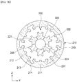
- the plurality of rotor iron core 340 and the plurality of permanent magnets 330 are coupled to each other in the circumferential direction between the rotor iron cores 340 so as to be rotatably installed, and also, the rotor 300 may be variously configured.
- the rotor 300 may include a plurality of rotor iron cores 340 and a plurality of permanent magnets 330, which are coupled to each other in the circumferential direction.
- the rotor 300 may have various shapes such as including a cylindrical portion which has a cylindrical shape and in which a plurality of rotor iron cores 340 and a plurality of permanent magnets 330 are coupled to each other in the circumferential direction between the rotor iron cores 340 and a rotating shaft 310 for transmitting rotational force to the outside - the generator has a rotating shaft 310 that allows the rotor 300 to rotate by external mechanical power -.
- cylindrical portion may be determined in arrangement and number of the permanent magnets 340 according to the design of the outer circumferential surface thereof.
- the cylindrical portion may define a cylindrical shape as a whole, and the rotor iron cores 340 and the permanent magnets 330 may be sequentially disposed on the cylindrical portion.
- the direction of the magnetic pole is defined with ⁇ ⁇ polarities in the circumferential direction to improve an output power by concentrating the magnetic flux.
- the electric motor may include a housing 100 to which the outer stator 210 is fixed.
- the inner support 400 may be configured to support the inner stator 220 so that the rotor 300 is rotatable in the first air gap 610 and the second air gap 620 and also may be variously configured such as being installed as a member that is integrated with or separated from the inner stator.
- the inner support 400 may be fixedly installed in the housing 100 so that the inner support 400 is inserted into the rotor 300 to rotatably support the rotor 300.
- the inner support 400 may be variously configured such as being installed to pass through a through-hole defined in the longitudinal direction of the inner stator 220 so that the inner support 400 is inserted into the inner stator 220, which will be described later, to support the inner stator 220.
- the inner support 400 may have one end (a left end in the drawing) fixedly installed in the housing 100 and the other end (a right end in the drawing) on which an inner support outer bearing 921 or a rotator horizontal hub bearing 923 is installed to support the rotor to be rotatable directly or indirectly.
- the inner support 400 may be installed in the housing 100 in various methods such as being integrally or detachably assembled so as not to rotate with respect to the housing 100.
- the inner support 400 may have one end (a left end in the drawing) coupled to the housing 100 and inserted and installed into the rotor 300, and the rotor 300 may be directly or indirectly supported on the other end (a right end in the drawing) of the inner support 400.
- the inner support 400 may have an outer diameter less than an inner diameter of the rotor 300 (or the rotor 300 or a rotor horizontal hub 381, which will be described later) so as not to adequately support the rotor 300 (or the rotor 300 or the rotor horizontal hub 381, which will be described later).
- an auxiliary support 410 that expands the outer diameter may be coupled to an end of the inner support 400 so that the inner support 400 rotatably supports the rotor 300 (or the rotor 300 or the rotor horizontal hub 381, which will be described later) by the rotator horizontal hub bearing 923.
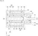
- the electric motor according to the first embodiment of the present invention includes the housing 100.
- the housing may include a housing body 110 to which the outer stator is coupled therein; and housing members 120 and 130 respectively coupled to both ends of the housing body 110.
- the housing members 120 and 130 may be configured to be coupled to both the ends of the housing body 110 and may include a first housing body in which an opening, through which at least a portion of the rotating shaft 310 or the rotor 300 is exposed is defined, and a second housing member coupled to the housing body 110 at a position facing the first housing member 120.
- any one of the housing members 120 and 130 may be configured so that at least a portion of the rotor 300 is exposed to the outside.
- the inner stator 220 may be constituted by only the iron cores without the inner winding 520 in the configuration according to the first embodiment of the present invention.
- the electric motor according to the second embodiment of the present invention have the same as that according to the first embodiment except that the inner winding 520 is not wound, and thus, detailed description thereof will be omitted.
- the rotor 300 may be variously configured according to the coupling structure with the rotating shaft 310 and the rotatable support structure with respect to the housing 100.
- a rotor central shaft hub 380 connected to the rotating shaft 310 of the rotor 300 and installed in the housing 100 may be coupled to at least one end of both ends of the rotor 300.
- the rotor central shaft hub 380 may be configured to be coupled to at least one end of both the ends of the rotor 300 to define a cylindrical shape as a whole.
- the housing 100 may be provided with an inner support 400 for supporting the inner stator 220 so that the rotor 300 rotates while maintaining the first air gap 610 and the second air gap 620.
- the inner support 400 may be configured to support the inner stator 220 so that the rotor 300 rotates while maintaining the first air gap 610 and the second air gap 620 and also may be variously configured.
- the inner support 400 may rotatably support the rotor central shaft hub 380 by an inner support outer bearing 921.
- the rotor central shaft hub 380 may have various support structures by the inner support 400. As illustrated in FIGS. 2 and 4 ( FIGS. 12a and 12b ), a portion of the end thereof may be inserted into the rotor central shaft hub 380, and thus, the rotor central shaft hub 380 may be rotatably supported by the inner support outer bearing 921 installed in the inserted portion.
- an inner circumferential surface of the rotor central shaft hub 380 may be supported so that the rotor central shaft hub 380 is rotatably supported by the inner support outer bearing 921.
- the housing 100 may have an opening 121 through which the rotating shaft 310 is exposed to the outside in consideration that the rotor central shaft hub 380 is installed in the housing 100.
- the rotating shaft 310 may be rotatably supported by one or more shaft support bearings 911 and 912 installed in the housing 100, for example, a first shaft support bearing 911 and a second shaft support bearing 912.
- a portion disposed inside the housing 100 i.e., a coupling part 313 coupled to the rotor central shaft hub 380 has an outer diameter greater than that of a portion that protrudes to the outside of the housing 100 so as to be smoothly supported by the first shaft support bearing 911.
- the first housing member 120 of the housing 100 may have a shape corresponding to an outer appearance of the coupling part 313.
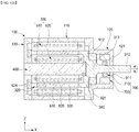
- At least one end of both ends of the rotor 300 may be connected to the rotating shaft 310 of the rotor 300 and coupled to a rotor horizontal hub 381 that protrudes to the outside of the housing 100.
- the rotor horizontal hub 381 may be variously configured such as being connected to the rotating shaft 310 of the rotor 300 at at least one end of both the ends of the rotor 300 and protruding to the outside of the housing 100.
- the rotor horizontal hub 381 may be configured to be coupled to at least one end of both the ends of the rotor 300 to define a cylindrical shape as a whole.
- an outer circumferential surface of the rotor horizontal hub 381 may be rotatably supported by a rotor horizontal hub bearing 923 installed in the housing 100.
- the housing 100 may be provided with an inner support 400 for supporting the inner stator 220 so that the rotor 300 rotates while maintaining the first air gap 610 and the second air gap 620.
- the rotor horizontal hub 381 may have various support structures by the inner support 400. For example, a portion of the end thereof may be inserted into the rotor horizontal hub 381, and thus, the rotor horizontal hub 381 may be rotatably supported by the rotor horizontal hub bearing 923 installed in the inserted portion.
- an inner circumferential surface of the rotor horizontal hub 381 may be supported so that the rotor horizontal hub 381 is rotatably supported by the rotor horizontal hub bearing 923.
- the rotor 300 may include an extension part 320 having one end (a right portion in the drawing) coupled to the rotor central shaft hub 380 or the rotor horizontal hub 381, which is connected to the rotating shaft 310 of the rotor 300 described above and the other end (a left portion in the drawing) that is rotatably supported by the bearing installed in the housing 100.
- the extension part 320 may be a portion that is coupled to the rotor 300 at an end opposite to the end, to which the rotor central shaft hub 380 or the rotor horizontal hub 381 is coupled, so as to be rotatably supported by the bearing installed in the housing 100 and may have a cylindrical shape together with the above-described rotor 300 and a hub part 380 as a whole.
- the bearing rotatably supporting the extension part 320 may be installed to the housing 100 to rotatably support the extension part 320.
- the bearing may be provided as an inner support bearing 925 installed on an inner circumferential surface of the extension part 320 as illustrated in FIGS. 12a and 12c or be provided as a rotor surface bearing 924 installed on an end of the extension part 320 or an inner surface of the housing 100, i.e., rotatably supporting the rotating shaft 310 of the extension part 320 as illustrated in FIGS. 12b and 12d and also may be variously configured.
- FIGS. 2 and 4 that illustrate the embodiments for the coupling of the rotating shaft 310 may illustrate a case in which a configuration in which the rotating shaft 310 is withdrawn from a center of the electric motor, i.e., the rotor central shaft hub 380 coupled to the rotor 300 inside the housing 100.
- FIGS. 5 and 6 may illustrate a case in which the rotor horizontal hub 381 extending parallely from the rotor 300 is exposed to the outside, and then, the rotating shaft 310 is coupled to the rotor horizontal hub 381 that is exposed to the outside.
- the iron cores of the outer stator 210 and the inner stator 220 may be various embodiments.
- the outer stator iron core 211 of the outer stator 210 may be divided into a plurality of parts in the circumferential direction, and the inner stator iron core 221 of the inner stator 220 may have an integrally cylindrical shape.
- the plurality of divided outer stator iron cores 211 may have fixing structures 215 on both side surfaces that are in close contact with the outer stator iron cores 211 adjacent to each other.
- the fixing structures 215 may be provided on the contact surface on which the plurality of divided outer stator iron cores 211 are in close contact with each other and have various structures as a structure for fixing the plurality of outer stator iron cores 211.
- the outer stator 210 may have a cylindrical shape by the plurality of divided outer stator iron cores 211. Furthermore, when divided into the outer stator winding slots 213 and coupled to the outer stator iron core 211 that is disposed adjacent in the state in which the outer winding 510 is wound, the outer winding 510 may be easily wound, and also, an overall assembly of the outer stator 210 may be easy.
- the outer stator iron core 211 of the outer stator 210 may have an integrally cylindrical shape, and the inner stator iron core 221 of the inner stator 220 may be divided into a plurality of parts in the circumferential direction.
- the inner stator iron core 221 may be divided into the plurality of parts in the circumferential direction, and the divided inner stator iron cores 221 may be coupled to each other in the circumferential direction to define a cylindrical shape as a whole.
- the plurality of divided inner stator iron cores 221 may have fixing structures 225 on both side surfaces that are in close contact with the inner stator iron cores 221 adjacent to each other.
- the fixing structure 225 may include: one or more protrusions protruding from one surface that is in close contact with the divided inner stator iron core 221 disposed at an adjacent position; recess portions in the other surface, which are defined to correspond to the protrusions.
- the inner stator 220 may have a cylindrical shape by the plurality of divided inner stator iron cores 221. Furthermore, when divided into the inner stator winding slots 223 and coupled to the inner stator iron core 221 that is disposed adjacent in the state in which the inner winding 520 is wound, the inner winding 520 may be easily wound, and also, an overall assembly of the inner stator 220 may be easy.
- each of the outer stator iron core 211 of the outer stator 210 and the inner stator iron core 221 of the inner stator 220 may have an integrally cylindrical shape.
- the outer stator 210 may have the cylindrical shape without being divided, and the inner stator 220 may be divided in the circumferential direction to provide the cylindrical shape as a whole.
- all of the outer stator iron core 211 of the outer stator 210 and the inner stator iron core 221 of the inner stator 220 may be divided in the circumferential direction to provide the cylindrical shape as a whole.
- windings corresponding to the respective phases may be connected to each other in series or in parallel so that power is applied thereto.
- various connections may be realized such as the serial or parallel connection of A1 + -A 1 - and A 2 + -A 2 - , the serial or parallel connection of B1 + -B 1 - and B 2 + -B 2 - , and the serial or parallel connection of C 1 + -C 1 - and C 2 + -C 2 - .
- outer windings 510 and the inner winding 520 are connected to each other, as illustrated in FIG. 9a , it is preferable that the outer windings 510 and the inner winding 520 are connected in series in whole, or connected in parallel to each other so that internal circulation current does not occur as illustrated in FIG. 9b .
- the inner stator winding slots 223 may be provided in 3n slots (n is a natural number greater than or equal to 2) in the inner stator 220 to apply or generate three-phase power, and the inner windings 520 wound on the inner stator winding slots 223 may be provided as a 1 to a n windings, b 1 to b n windings, and C 1 to C n windings, in which the three-phase power is applied in order of a, b and c with respect to the respective inner stator winding slots 223 in the circumferential direction.
- the inner windings 520 may be arranged in order of a1 + -a 1 - , b1 + -b 1 - , c1 + -C1 - , a 2 + -a 2 - , b 2 + -b 2 - , and C 2 + -C 2 - in the circumferential direction to correspond to the three-phase power.
- windings corresponding to the respective phases may be connected to each other in series or in parallel so that power is applied thereto.
- various connections may be realized such as the serial or parallel connection of a1 + -a 1 - and a 2 + -a 2 - , the serial or parallel connection of b 1 + -b 1 - and b 2 + -b 2 - , and the serial or parallel connection of C 1 + -C 1 - and C 2 + -C 2 - .
- the winding may be connected in various manners.
- a 1 to a n may be connected in series or in parallel.
- b 1 to b n may be connected in series or in parallel
- the C 1 to C n may be connected in series or in parallel.
- a 1 to a n may be connected in series or in parallel.
- b 1 to b n may be connected in series or in parallel
- the c 1 to c n may be connected in series or in parallel.
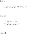
- FIGS. 9a to 9c For another example of the combination of the outer windings 510 and the inner windings 520, various embodiments may be realized as illustrated in FIGS. 9a to 9c .
- the windings corresponding to one phase may be connected in series in order of A 1 + -A 1 - -a 1 + -a 1 - - and A 2 + -A 2 - -a 2 + -a 2 .
- the outer windings 510 and the inner windings 520 may be connected in series as a whole.
- the windings A 1 + -A 1 - -a 1 + -a 1 - and A 2 + -A 2 - -a 2 + -a 2 may be connected in series and then connected in parallel to each other.
- the outer windings 510 and the inner windings 520 are connected to each other, the outer winding 510 and the inner winding 520 in each phase in which a plurality of phases of respective power are disposed are connected in series, and the phases provided in plurality may be connected in parallel to each other.
- phase of the three phases is illustrated, it is of course possible to be Y or ⁇ connected to the remaining two phases.
- the electric motor includes the rotating shaft 310 of the rotor 30 to control the rotation thereof and the rotor position sensor 700 installed in the housing 100 to sense a rotation position of the rotor 300.
- the rotor position sensor 700 may be installed to sense the rotation position of the rotor 300 with respect to the housing 100 in a relatively fixed state.
- the rotor position sensor 700 may have various configurations as long as the rotor position sensor 700 senses the rotation position of the rotor 300.
- the rotor position sensor 700 may be installed at various positions according to the shapes and structures of the housing 100, the outer stator 210, and the rotor 300.
- the rotor position sensor 700 may include one or more first sensing parts 710 installed on the rotating shaft 310 of the rotor 300 to rotate and second sensing parts 720 installed in the housing 100 to sense a position of the first sensing parts 710.
- the first sensing parts 710 may be constituted by a plurality of magnetic body protrusions protruding in the radial direction
- the second sensing parts 710 may be constituted by two sensing parts corresponding to the magnetic body protrusions that are the first sensing parts 710.
- the plurality of magnetic body protrusions of the first sensing parts 710 may be configured to protrude in the radial direction on the rotating shaft 310 of the rotor 300 and may be integrated with the rotating shaft 310 or provided as separate members and then coupled to the rotating shaft 310.
- the configuration of the magnetic body protrusions may have a structure similar to the structure disclosed in Patent Document 1.
- the linear structure is disclosed in Patent Document 1
- the magnetic body protrusions may be modified so that the protrusion configuration and the sensor module are arranged in a circular shape.
- each of the magnetic body protrusions may be provided so that an angle is 2 ⁇ in the circumferential direction.
- two sensor modules of the second sensing parts 720 may be installed to correspond to the arrangement of the magnetic body protrusions of the first sensing parts 710. Among them, it is preferable that one sensing module and the other sensing module of the second sensing parts 720 are disposed to be angled at an angle difference of ⁇ /2 with respect to the magnetic body protrusions.
- the sensing sensors may sense the rotating shaft 310, i.e., the rotation position of the rotor 300 by using the formula expressed in FIG. 6 of Patent Document 1.
- the rotor 300 and the rotating shaft 310 may be coupled to each other in various manners. That is, the coupling of the rotor 300 and the rotating shaft 310 may be applied to the general electric motor according to the related art, i.e., the induction motor, the permanent magnet motor, and the like to increase in output without being limited to the embodiments of the double air gap electric motor according to the present invention.
- the general electric motor i.e., the induction motor, the permanent magnet motor, and the like to increase in output without being limited to the embodiments of the double air gap electric motor according to the present invention.
- the second air gap i.e., two air gaps between the outside of the first air gap 610 and the inner stator 520 and the rotor 300 may be defined between the inside of the outer stator 210 and the rotor 300.
- the rotor 300 of the double air gap electric motor may function as the rotating parts of the inner rotor type electric motor and the outer rotor type electric motor at the same time to increase in a mechanical output power in a given volume (an amount of power to be generated in the case of the generator).
- the double air gap electric motor may have two windings 500.
- the outer winding 510 may be provided in the outer stator 210
- the inner winding 520 may be provided in the inner stator 220.
- the structure of the double air gap motor may be variously configured according to the shapes of the rotor and the rotating shaft and the position of the bearing.
- examples of the structure of the double air gap electric motor are divided according to the position at which the rotor 300 and the rotating shaft 310 are coupled and according to the shapes of the rotor and the rotating shaft.
- An end of the rotor 300 i.e., the bearings 924 and 925 supporting the extension part 320 may be disposed at various positions.
- the bearings 924 and 925 supporting the extension part 320 may be provided as an inner support bearing 925 on the inner circumferential surface of the extension part 320, or as illustrated in FIGS. 12b and 12d , the bearings 924 and 925 supporting the extension part 320 may be provided as a rotor side surface bearing 924 between the ends of the extension part 320 and the inner surface of the housing 100.
- FIGS. 12a to 12d and the above-described configuration are related to the installation structure of the rotor 300 and the rotating shaft 310 regardless of the type of the electric motor such as the winding of the coil winding and also variously modified.
- an electric motor may include: a rotor 300 of which one end of both ends is connected to a rotating shaft 310 that transmits rotational force to the outside; and one or more stators 210 and 220 having two air gaps 610 and 620 respectively defined in outer and inner circumferential surfaces of the rotor 300.
- the stators 210 and 220 include: an outer stator 210 installed with an outer circumferential surface of the rotor 300 and a first air gap 610; and an inner stator 220 installed with an inner circumferential surface of the rotor 300 and a second air gap 620.
- the rotor 300 may be configured in various manners, such as those according to the embodiments illustrated in FIGS. 2 , 4 to 6 , and 12a to 12d .
- force per unit area on the outer circumferential surface of the rotor is defined as a value obtained by dividing force generated in the rotating shaft 310 by the surface area of the rotor.
Landscapes
- Engineering & Computer Science (AREA)
- Power Engineering (AREA)
- Microelectronics & Electronic Packaging (AREA)
- Manufacturing & Machinery (AREA)
- Iron Core Of Rotating Electric Machines (AREA)
Applications Claiming Priority (2)
| Application Number | Priority Date | Filing Date | Title |
|---|---|---|---|
| KR1020170126345A KR102534232B1 (ko) | 2017-09-28 | 2017-09-28 | 회전 전기기기 |
| PCT/KR2018/011419 WO2019066487A1 (fr) | 2017-09-28 | 2018-09-27 | Dispositif électrique tournant |
Publications (2)
| Publication Number | Publication Date |
|---|---|
| EP3691086A1 true EP3691086A1 (fr) | 2020-08-05 |
| EP3691086A4 EP3691086A4 (fr) | 2021-06-16 |
Family
ID=65902600
Family Applications (1)
| Application Number | Title | Priority Date | Filing Date |
|---|---|---|---|
| EP18862258.3A Pending EP3691086A4 (fr) | 2017-09-28 | 2018-09-27 | Dispositif électrique tournant |
Country Status (5)
| Country | Link |
|---|---|
| US (1) | US11289956B2 (fr) |
| EP (1) | EP3691086A4 (fr) |
| KR (1) | KR102534232B1 (fr) |
| CN (1) | CN111149280B (fr) |
| WO (1) | WO2019066487A1 (fr) |
Families Citing this family (14)
| Publication number | Priority date | Publication date | Assignee | Title |
|---|---|---|---|---|
| GB201720363D0 (en) * | 2017-12-06 | 2018-01-17 | Trw Ltd | Handwheel actuator assembly |
| GB201900536D0 (en) * | 2019-01-15 | 2019-03-06 | Rolls Royce Plc | Electromechanical system |
| US20230018260A1 (en) * | 2019-12-20 | 2023-01-19 | Vam Co., Ltd. | Dual and multiple air gap rotary device |
| TWI729648B (zh) * | 2019-12-23 | 2021-06-01 | 綠達光電股份有限公司 | 模組化馬達轉子及模組化馬達轉子結構 |
| KR102504873B1 (ko) * | 2020-11-27 | 2023-02-28 | 경성대학교 산학협력단 | 복식 제어장치를 구비한 이중 공극형 표면 영구자석 동기모터 |
| KR102449014B1 (ko) * | 2020-11-27 | 2022-09-28 | 경성대학교 산학협력단 | 비자성 차단부재를 구비한 이중 공극형 표면 영구자석 동기모터 |
| US11641150B2 (en) * | 2021-02-25 | 2023-05-02 | O Chan KWON | Smart generator |
| KR102542504B1 (ko) * | 2021-03-04 | 2023-06-12 | 한양대학교 에리카산학협력단 | 에너지 변환 장치 |
| KR102568399B1 (ko) * | 2021-07-01 | 2023-08-21 | 인천대학교 산학협력단 | 요크리스 회전자를 이용한 이중 공극 방사형 자속 영구 자석 버니어 전동기 |
| KR102564286B1 (ko) * | 2021-07-20 | 2023-08-04 | 한양대학교 에리카산학협력단 | 에너지 변환 장치 |
| KR20230057809A (ko) | 2021-10-22 | 2023-05-02 | 주식회사 브이에이엠 | 상반회전 프로펠러를 가지는 고효율 회전기기 |
| CN114673664A (zh) * | 2022-03-25 | 2022-06-28 | 合肥恒大江海泵业股份有限公司 | 一种自体供电电泵 |
| KR102685213B1 (ko) * | 2022-06-09 | 2024-07-12 | 김대연 | 자석의 Metal Magnet Interaction (MMI) 현상을 이용한 이중척력 장치 |
| US20240072623A1 (en) * | 2022-08-26 | 2024-02-29 | NextPower360 Co. | Improved intrinsically adapting variable generators and motors |
Family Cites Families (20)
| Publication number | Priority date | Publication date | Assignee | Title |
|---|---|---|---|---|
| JPH0742226Y2 (ja) * | 1985-02-22 | 1995-09-27 | 三菱電機株式会社 | 永久磁石界磁形同期機 |
| DE3915526A1 (de) * | 1989-02-13 | 1990-08-16 | Rolf Hopf | Duplexelektromotor |
| JP3152405B2 (ja) * | 1992-06-10 | 2001-04-03 | オークマ株式会社 | 電動機 |
| JP3691345B2 (ja) * | 2000-05-25 | 2005-09-07 | 三菱電機株式会社 | 永久磁石型電動機 |
| KR100440389B1 (ko) | 2001-12-26 | 2004-07-14 | 한국전기연구원 | 2상 횡자속형 영구자석 여자 선형 전동기 |
| US6924574B2 (en) * | 2003-05-30 | 2005-08-02 | Wisconsin Alumni Research Foundation | Dual-rotor, radial-flux, toroidally-wound, permanent-magnet machine |
| KR100785276B1 (ko) | 2005-12-29 | 2007-12-13 | 한국전기연구원 | 외전형 영구자석 여자 횡자속 전동기 |
| KR101273594B1 (ko) * | 2007-04-05 | 2013-06-14 | 삼성전자주식회사 | 모터 및 이를 갖춘 드럼세탁기 |
| KR101027935B1 (ko) | 2008-10-21 | 2011-04-12 | 한국전기연구원 | 선형 위치 검출용 자기 센서 및 이를 이용한 선형 전동기 위치 검출 방법 |
| CN101741155B (zh) * | 2008-11-14 | 2012-09-05 | 山东科汇电力自动化有限公司 | 一种开关磁阻发电机 |
| JP5359398B2 (ja) * | 2009-03-10 | 2013-12-04 | マツダ株式会社 | ハイブリッド車両の制御装置 |
| KR101265994B1 (ko) * | 2011-04-04 | 2013-05-22 | 오장수 | 전기 자동차용 구동장치 및 이의 제어방법 |
| CN202282690U (zh) * | 2011-10-28 | 2012-06-20 | 雅科贝思精密机电(上海)有限公司 | 一种高转矩低惯性的直接驱动电机 |
| CN102427290A (zh) * | 2011-10-28 | 2012-04-25 | 雅科贝思精密机电(上海)有限公司 | 一种高转矩低惯性的直接驱动电机 |
| JP6095267B2 (ja) * | 2012-02-24 | 2017-03-15 | 株式会社クリーンクラフト | 三相永久磁石式同期モータ |
| US9595858B2 (en) | 2013-09-09 | 2017-03-14 | Wisconsin Alumni Research Foundation | Double air gap, spoke type vernier machine |
| CN103618424B (zh) * | 2013-12-02 | 2016-08-17 | 南京工程学院 | 一种双定子磁悬浮开关磁阻启动/发电机 |
| JP6393916B2 (ja) * | 2014-02-20 | 2018-09-26 | 北田回転機関合同会社 | 電気回転機 |
| JP5901678B2 (ja) * | 2014-03-27 | 2016-04-13 | 株式会社豊田中央研究所 | 情報処理装置、情報記憶装置、及び回転電機の制御装置 |
| CN106602823A (zh) | 2017-02-23 | 2017-04-26 | 武汉理工大学 | 一种双爪极定子聚磁式游标电机 |
-
2017
- 2017-09-28 KR KR1020170126345A patent/KR102534232B1/ko active IP Right Grant
-
2018
- 2018-09-27 CN CN201880063789.1A patent/CN111149280B/zh active Active
- 2018-09-27 WO PCT/KR2018/011419 patent/WO2019066487A1/fr unknown
- 2018-09-27 US US16/651,941 patent/US11289956B2/en active Active
- 2018-09-27 EP EP18862258.3A patent/EP3691086A4/fr active Pending
Also Published As
| Publication number | Publication date |
|---|---|
| WO2019066487A1 (fr) | 2019-04-04 |
| US20200303973A1 (en) | 2020-09-24 |
| CN111149280B (zh) | 2023-06-30 |
| EP3691086A4 (fr) | 2021-06-16 |
| KR20190036890A (ko) | 2019-04-05 |
| US11289956B2 (en) | 2022-03-29 |
| CN111149280A (zh) | 2020-05-12 |
| KR102534232B1 (ko) | 2023-05-18 |
Similar Documents
| Publication | Publication Date | Title |
|---|---|---|
| US11289956B2 (en) | Rotating electric device | |
| JP7095731B2 (ja) | 回転電機 | |
| US7592728B2 (en) | Electric machine having segmented stator | |
| US8552609B2 (en) | Synchronous motor and system for driving synchronous motor | |
| JP5751794B2 (ja) | 電気式乗物のための牽引モータ | |
| JP5060839B2 (ja) | 電動機 | |
| US9236784B2 (en) | Flux-switching electric machine | |
| EP3208918B1 (fr) | Machine rotative de type à double stator | |
| KR20210120082A (ko) | 축 방향 자속 전기 기계 | |
| CN102055294B (zh) | 永磁倍极开关磁阻电动机 | |
| US20150022043A1 (en) | Electric motor | |
| JP6958504B2 (ja) | 回転電機の固定子 | |
| KR20210120081A (ko) | 축 방향 자속 전기 기계 | |
| US20150061451A1 (en) | Electric motor | |
| Sarshar et al. | Analysis of a Synthesized Slot Permanent Magnet Flux Reversal Motor | |
| CN102570656A (zh) | 一种电励磁无刷起动、发电机 | |
| CN202395551U (zh) | 一种电励磁无刷起动、发电机 | |
| CN202798174U (zh) | 分立电磁铁定子结构的新型永磁电机 | |
| CN102545423B (zh) | 横向磁场永磁电机 | |
| KR20210074696A (ko) | 다단의 회전자를 구비한 고속 전동기 | |
| CN214480207U (zh) | 碟式电机 | |
| JP2005253280A (ja) | リング状の固定子コイルを有するアウターロータ形のブラシレスdcモータ及びacサーボモータ | |
| KR20130102315A (ko) | 대용량 발전기 | |
| CN106921273B (zh) | 免换向结构的永磁直流电机 | |
| CN116247845A (zh) | 一种转子聚磁式分段定子横向磁通永磁轮毂电机 |
Legal Events
| Date | Code | Title | Description |
|---|---|---|---|
| STAA | Information on the status of an ep patent application or granted ep patent |
Free format text: STATUS: THE INTERNATIONAL PUBLICATION HAS BEEN MADE |
|
| PUAI | Public reference made under article 153(3) epc to a published international application that has entered the european phase |
Free format text: ORIGINAL CODE: 0009012 |
|
| STAA | Information on the status of an ep patent application or granted ep patent |
Free format text: STATUS: REQUEST FOR EXAMINATION WAS MADE |
|
| 17P | Request for examination filed |
Effective date: 20200428 |
|
| AK | Designated contracting states |
Kind code of ref document: A1 Designated state(s): AL AT BE BG CH CY CZ DE DK EE ES FI FR GB GR HR HU IE IS IT LI LT LU LV MC MK MT NL NO PL PT RO RS SE SI SK SM TR |
|
| AX | Request for extension of the european patent |
Extension state: BA ME |
|
| DAV | Request for validation of the european patent (deleted) | ||
| DAX | Request for extension of the european patent (deleted) | ||
| REG | Reference to a national code |
Ref country code: DE Ref legal event code: R079 Free format text: PREVIOUS MAIN CLASS: H02K0001160000 Ipc: H02K0021220000 |
|
| A4 | Supplementary search report drawn up and despatched |
Effective date: 20210514 |
|
| RIC1 | Information provided on ipc code assigned before grant |
Ipc: H02K 21/22 20060101AFI20210508BHEP Ipc: H02K 21/16 20060101ALI20210508BHEP Ipc: H02K 21/14 20060101ALI20210508BHEP Ipc: H02K 16/04 20060101ALI20210508BHEP Ipc: H02K 1/14 20060101ALI20210508BHEP Ipc: H02K 1/16 20060101ALN20210508BHEP Ipc: H02K 1/27 20060101ALN20210508BHEP Ipc: H02K 7/08 20060101ALN20210508BHEP |
|
| STAA | Information on the status of an ep patent application or granted ep patent |
Free format text: STATUS: EXAMINATION IS IN PROGRESS |
|
| 17Q | First examination report despatched |
Effective date: 20230323 |