EP3690987B1 - Unit module including busbar frame structure which can facilitate welding, and battery module including same - Google Patents
Unit module including busbar frame structure which can facilitate welding, and battery module including same Download PDFInfo
- Publication number
- EP3690987B1 EP3690987B1 EP19788743.3A EP19788743A EP3690987B1 EP 3690987 B1 EP3690987 B1 EP 3690987B1 EP 19788743 A EP19788743 A EP 19788743A EP 3690987 B1 EP3690987 B1 EP 3690987B1
- Authority
- EP
- European Patent Office
- Prior art keywords
- bus bar
- frame
- electrode lead
- unit
- bar frame
- Prior art date
- Legal status (The legal status is an assumption and is not a legal conclusion. Google has not performed a legal analysis and makes no representation as to the accuracy of the status listed.)
- Active
Links
Images

Classifications
-
- H—ELECTRICITY
- H01—ELECTRIC ELEMENTS
- H01M—PROCESSES OR MEANS, e.g. BATTERIES, FOR THE DIRECT CONVERSION OF CHEMICAL ENERGY INTO ELECTRICAL ENERGY
- H01M50/00—Constructional details or processes of manufacture of the non-active parts of electrochemical cells other than fuel cells, e.g. hybrid cells
- H01M50/50—Current conducting connections for cells or batteries
- H01M50/502—Interconnectors for connecting terminals of adjacent batteries; Interconnectors for connecting cells outside a battery casing
-
- H—ELECTRICITY
- H01—ELECTRIC ELEMENTS
- H01M—PROCESSES OR MEANS, e.g. BATTERIES, FOR THE DIRECT CONVERSION OF CHEMICAL ENERGY INTO ELECTRICAL ENERGY
- H01M10/00—Secondary cells; Manufacture thereof
- H01M10/04—Construction or manufacture in general
- H01M10/0413—Large-sized flat cells or batteries for motive or stationary systems with plate-like electrodes
-
- H—ELECTRICITY
- H01—ELECTRIC ELEMENTS
- H01M—PROCESSES OR MEANS, e.g. BATTERIES, FOR THE DIRECT CONVERSION OF CHEMICAL ENERGY INTO ELECTRICAL ENERGY
- H01M50/00—Constructional details or processes of manufacture of the non-active parts of electrochemical cells other than fuel cells, e.g. hybrid cells
- H01M50/20—Mountings; Secondary casings or frames; Racks, modules or packs; Suspension devices; Shock absorbers; Transport or carrying devices; Holders
- H01M50/204—Racks, modules or packs for multiple batteries or multiple cells
- H01M50/207—Racks, modules or packs for multiple batteries or multiple cells characterised by their shape
- H01M50/211—Racks, modules or packs for multiple batteries or multiple cells characterised by their shape adapted for pouch cells
-
- H—ELECTRICITY
- H01—ELECTRIC ELEMENTS
- H01M—PROCESSES OR MEANS, e.g. BATTERIES, FOR THE DIRECT CONVERSION OF CHEMICAL ENERGY INTO ELECTRICAL ENERGY
- H01M50/00—Constructional details or processes of manufacture of the non-active parts of electrochemical cells other than fuel cells, e.g. hybrid cells
- H01M50/50—Current conducting connections for cells or batteries
- H01M50/531—Electrode connections inside a battery casing
-
- B—PERFORMING OPERATIONS; TRANSPORTING
- B23—MACHINE TOOLS; METAL-WORKING NOT OTHERWISE PROVIDED FOR
- B23K—SOLDERING OR UNSOLDERING; WELDING; CLADDING OR PLATING BY SOLDERING OR WELDING; CUTTING BY APPLYING HEAT LOCALLY, e.g. FLAME CUTTING; WORKING BY LASER BEAM
- B23K2101/00—Articles made by soldering, welding or cutting
- B23K2101/36—Electric or electronic devices
- B23K2101/38—Conductors
-
- H—ELECTRICITY
- H01—ELECTRIC ELEMENTS
- H01M—PROCESSES OR MEANS, e.g. BATTERIES, FOR THE DIRECT CONVERSION OF CHEMICAL ENERGY INTO ELECTRICAL ENERGY
- H01M2220/00—Batteries for particular applications
- H01M2220/20—Batteries in motive systems, e.g. vehicle, ship, plane
-
- Y—GENERAL TAGGING OF NEW TECHNOLOGICAL DEVELOPMENTS; GENERAL TAGGING OF CROSS-SECTIONAL TECHNOLOGIES SPANNING OVER SEVERAL SECTIONS OF THE IPC; TECHNICAL SUBJECTS COVERED BY FORMER USPC CROSS-REFERENCE ART COLLECTIONS [XRACs] AND DIGESTS
- Y02—TECHNOLOGIES OR APPLICATIONS FOR MITIGATION OR ADAPTATION AGAINST CLIMATE CHANGE
- Y02E—REDUCTION OF GREENHOUSE GAS [GHG] EMISSIONS, RELATED TO ENERGY GENERATION, TRANSMISSION OR DISTRIBUTION
- Y02E60/00—Enabling technologies; Technologies with a potential or indirect contribution to GHG emissions mitigation
- Y02E60/10—Energy storage using batteries
-
- Y—GENERAL TAGGING OF NEW TECHNOLOGICAL DEVELOPMENTS; GENERAL TAGGING OF CROSS-SECTIONAL TECHNOLOGIES SPANNING OVER SEVERAL SECTIONS OF THE IPC; TECHNICAL SUBJECTS COVERED BY FORMER USPC CROSS-REFERENCE ART COLLECTIONS [XRACs] AND DIGESTS
- Y02—TECHNOLOGIES OR APPLICATIONS FOR MITIGATION OR ADAPTATION AGAINST CLIMATE CHANGE
- Y02P—CLIMATE CHANGE MITIGATION TECHNOLOGIES IN THE PRODUCTION OR PROCESSING OF GOODS
- Y02P70/00—Climate change mitigation technologies in the production process for final industrial or consumer products
- Y02P70/50—Manufacturing or production processes characterised by the final manufactured product
Definitions
- the present disclosure relates to a unit module having a bus bar frame for facilitating welding and a battery module including the unit module, and more particularly to a unit module having a structure in which a bus bar frame has a welding slit to facilitate welding between an electrode lead and a bus bar and a battery module including the unit module.
- electrical connection between the battery cells is generally performed by welding electrode leads of the battery cells, which are to be electrically connected with each other, to one bus bar.
- the laser welding which is one of the methods of connecting the electrode lead and the bus bar, is performed in a state where the electrode lead is pressed toward the bus bar by using a welding jig capable of closely adhering the electrode lead and the bus bar of the battery cell, in order to improve the welding quality.
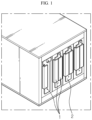
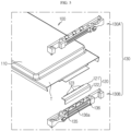
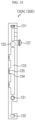
- FIG. 1 shows a conventional battery module.
- a pressing jig having a size and shape suitable for the corresponding model is required.
- the pressing jig for closely adhering the electrode lead and the bus bar should be prepared to have a different design suitable for battery modules having different sizes and shapes.
- the model in which the electrode lead and the bus bar should be welded using the pressing jig has limitations in terms of space and structure since a minimum space for placing the jig should be secured around a welding portion in order to apply the pressing jig for welding.
- US 2007/207377 A1 relates to a secondary battery and battery module having the same.
- the secondary battery is formed in the shape of a plate and has an electrode assembly mounted in a battery case made of a laminated sheet including a metal layer and a resin layer, wherein the secondary battery is constructed in a structure in which independent coupling type frame members are mounted to the outside part of a sheathing member serving as the battery case, and a medium- or large-sized battery module including the same as a unit cell.
- the present disclosure is designed to solve the problems of the related art, and therefore the present disclosure is directed to securing easy welding without preparing a dedicated welding jig for different battery modules since the bus bar frame may serve as the welding jig.
- a unit module as defined in claim 1 comprising: a pouch-type battery cell having an electrode assembly, a cell case for accommodating the electrode assembly, and an electrode lead connected to the electrode assembly and drawn out of the cell case; a bus bar attached to the electrode lead; and a bus bar frame attached to a terrace portion of the battery cell to accommodate at least a portion of the electrode lead and the bus bar therein, the bus bar frame pressing the electrode lead and the bus bar so that the electrode lead and the bus bar are closely adhered to each other, the bus bar frame having a welding slit formed at a location corresponding to the bus bar and the electrode lead so that a contact portion of the bus bar and the electrode lead is exposed out.
- the bus bar includes: a bonding portion extending in a direction parallel to the electrode lead to contact the electrode lead and located at an inner side of the bus bar frame; an exposed portion bent from the bonding portion to extend in a direction perpendicular to the bonding portion and drawn out of the bus bar frame; and a hook portion extending from an end of the bonding portion in a direction parallel to the exposed portion.
- the bus bar frame may include: a hook accommodation groove extending from the welding slit; and a hook fixing portion formed on an inner wall of the hook accommodation groove.
- the bus bar frame may include a bus bar placing portion having a size and shape corresponding to the exposed portion of the bus bar and formed concavely on an outer surface of the bus bar frame so that the exposed portion is placed thereon.
- the bus bar frame may have a damage-preventing groove formed on the placing portion to a predetermined depth so that the bus bar and the bus bar frame are partially not in contact to prevent the bus bar frame from being damaged due to heat caused by welding.
- a unit module as defined in claim 5 comprising: a pouch-type battery cell having an electrode assembly, a cell case for accommodating the electrode assembly, and an electrode lead connected to the electrode assembly and drawn out of the cell case; a bus bar attached to the electrode lead; and a bus bar frame attached to a terrace portion of the battery cell to accommodate at least a portion of the electrode lead and the bus bar therein, the bus bar frame pressing the electrode lead and the bus bar so that the electrode lead and the bus bar are closely adhered to each other, the bus bar frame having a welding slit formed at a location corresponding to the bus bar and the electrode lead so that a contact portion of the bus bar and the electrode lead is exposed out.
- the bus bar frame includes: a first unit frame configured to cover at least a portion of an upper surface of the terrace portion; and a second unit frame configured to cover at least a portion of a lower surface of the terrace portion and coupled to the first unit frame.
- the first unit frame and the second unit frame are shaped to be point-symmetric to each other.
- a battery module as defined in claim 6, comprising: a unit module stack formed by connecting a plurality of unit modules according to an embodiment of the present disclosure as described above; and a connector configured to connect bus bars of neighboring unit modules.
- a battery pack as defined in claim 7 which is implemented by connecting a plurality of battery modules according to an embodiment of the present invention as described above, and in another aspect of the present invention, there is also provided a vehicle as defined in claim 8, comprising the battery pack according to an embodiment of the present invention.
- the bus bar frame may serve as a welding jig, welding may be easily performed without preparing a dedicated welding jig for different battery modules.
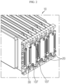
- FIG. 2 is a perspective view showing a portion of a battery module according to an embodiment of the present disclosure
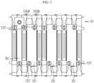
- FIG. 3 is a front showing a portion of the battery module according to an embodiment of the present disclosure
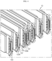
- FIG. 4 is a diagram showing a unit module stack applied to the battery module according to an embodiment of the present disclosure
- FIG. 5 is an exploded perspective view showing a unit module applied to the battery module according to an embodiment of the present disclosure.
- a battery module according to an embodiment of the present disclosure includes a unit module stack 10, a connector 20, and an external terminal 30.
- the unit module stack 10 is a stack implemented by stacking a plurality of unit modules 100.
- Each unit module 100 includes a battery cell 110, a bus bar 120 connected to an electrode lead 114 of the battery cell 110, and a bus bar frame 130 attached to a terrace portion T of the battery cell 110.
- the unit module stacks 10 are stacked such that broad surfaces of neighboring battery cells 110 face each other, thereby forming one unit module stack 10.
- the connector 20 is a component adapted to electrically connect neighboring unit module stacks 10, and the connector 20 connects bus bars 120 provided in the neighboring unit module stacks 10 to each other.
- the external terminal 30 contacts the bus bar 120 provided to the unit module 100 disposed at the outermost side among the plurality of unit modules 100 of the unit module stack 10 and functions as a terminal for electrical connection with an external electronic device.
- FIG. 5 is an exploded perspective view showing a unit module applied to the battery module according to an embodiment of the present disclosure
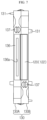
- FIG. 6 is a perspective view showing a battery cell applied to the battery module according to an embodiment of the present disclosure.
- the battery cell 110 may include an electrode assembly (not shown), a cell case 111, and an electrode lead 114.
- the electrode assembly is configured so that separators are interposed between positive electrode plates and negative electrode plates alternately stacked repeatedly, and separators are preferably disposed at both outermost sides thereof for insulation.
- the positive electrode plate includes a positive electrode current collector and a positive electrode active material layer coated on one or both surfaces of the positive electrode current collector.
- a positive electrode uncoated region where the positive electrode active material is not coated is formed at one end of the positive electrode plate.
- the positive electrode uncoated region functions as a positive electrode tab connected to the electrode lead 114.
- the negative electrode plate includes a negative electrode current collector and a negative electrode active material layer coated on one or both surfaces of the negative electrode current collector.
- a negative electrode uncoated region where the negative electrode active material is not coated is formed at one side of the negative electrode plate.
- the negative electrode uncoated region functions as a negative electrode tab connected to the electrode lead 114.
- the separator is interposed between the positive electrode plate and the negative electrode plate to prevent the electrode plates having different polarities from contacting each other directly.
- the separator may be made of a porous material to allow ions to move between the positive electrode plate and the negative electrode plate by using an electrolyte as a medium.
- the cell case 111 includes an accommodation portion 112 for accommodating the electrode assembly (not shown) and a sealing portion 113 extending in a circumferential direction of the accommodation portion so that the electrode lead 114 is thermally fused thereto in an outwardly drawn state to seal the cell case 111.
- the electrode lead 114 is classified into a positive electrode lead connected to the positive electrode tab and a negative electrode lead connected to the negative electrode tab, and the positive electrode lead and the negative electrode lead are drawn out of the cell case 111 in opposite directions.
- a region positioned in the direction to which the electrode lead 114 is drawn out is particularly defined as a terrace portion T.
- bus bar 120 of the unit module 100 will be described in detail with reference to FIG. 5 again.
- the bus bar 120 is bonded to the electrode lead 114 by welding in a state of being fixed to the bus bar frame 130, so that a portion of the bus bar 120 is located inside the bus bar frame 130 and the remaining portion is exposed out of the bus bar frame 130.
- the portion of the bus bar 120 exposed out of the bus bar frame 130 is connected to the connector 20 (see FIGS. 2 and 3 ) explained above, thereby electrically connecting neighboring battery unit modules 100.
- the bus bar 120 includes a bonding portion 121, an exposed portion 122, and a hook portion 123.
- the bonding portion 121 extends in a direction parallel to the electrode lead 114, namely in the horizontal direction, to contact the electrode lead 114 and is located inside the bus bar frame 130.
- the exposed portion 122 is bent from the bonding portion 121 and extends in a direction perpendicular to the bonding portion 121, and also the exposed portion 122 is drawn out of the bus bar frame 130 and placed on a bus bar placing portion 136, explained later.
- the hook portion 123 extends from an end of the bonding portion 121 in a direction parallel to the exposed portion 122, and one or more hook portions 123 are provided.
- the hook portion 123 allows the bus bar 120 to be fixed to the inside of the bus bar frame 130 and is coupled or fixed to a hook fixing portion 135 provided at an inner surface of the bus bar frame 130.
- the bus bar 120 is fixed and mounted inside the bus bar frame 130 so that a portion of the bus bar 120 is exposed out of the bus bar frame 130. Also, the bonding portion 121 located inside the bus bar frame 130 is bonded to the lower surface of the electrode lead 114, and the exposed portion 122 located at the outer side of the bus bar frame 130 is connected to the connector 20 to electrically connect neighboring unit modules 100 to each other.
- bus bar frame 130 of the unit module 100 will be described in detail with reference to FIGS. 7 to 10 along with FIG. 5 .
- FIG. 7 is a front showing that the unit module applied to the battery module according to an embodiment of the present disclosure is coupled to a bus bar
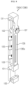
- FIGS. 8 and 9 are perspective views showing a unit frame of a bus bar frame applied to the battery module according to an embodiment of the present disclosure at different angles
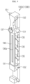
- FIG. 10 is a side view showing the unit frame of the bus bar frame applied to the battery module according to an embodiment of the present disclosure.
- the bus bar frame 130 is attached to the terrace portion T of the battery cell 110 and functions as a support for the bus bar 120 as described above.
- the bus bar frame 130 is implemented by combining a first unit frame 130A and a second unit frame 130B having the same shape. That is, the first unit frame 130A and the second unit frame 130B are components having the same shape, where the first unit frame 130A covers at least a portion of the upper surface of the terrace portion T and the second unit frame 130B covers at least a portion of the lower portion of the terrace portion T.
- the first unit frame 130A and the second unit frame 130B are coupled to each other.
- first unit frame 130A and the second unit frame 130B are coupled to each other to form one bus bar frame 130, the first unit frame 130A and the second unit frame 130B are point-symmetric to each other.
- the first unit frame 130A has the same shape as the second unit frame 130B.
- the bus bar 120 is drawn through a gap of the coupling surfaces thereof. That is, the exposed portion 122 of the bus bar 120 is drawn through the gap between the coupling surfaces of the first unit frame 130A and the second unit frame 130B.
- the drawn bus bar 120 is bent toward the first unit frame 130A or the second unit frame 130B and is placed on the bus bar placing portion 136 formed at the first unit frame 130A or the second unit frame 130B.
- the bending direction of the bus bar 120 is determined according to whether the bus bar 120 is electrically connected to the unit module 100 in contact with the first unit frame 130A or the unit module in contact with the second unit frame 130B.
- bus bar frame 130 As described above, since the pair of unit frames 130A, 130B are components having the same shape, the detailed structure of the bus bar frame 130 will be described based on one unit frame (130A or 130B) with reference to FIGS. 8 to 10 .
- the unit frames 130A, 130B may include a fixing protrusion 131, a protrusion accommodation groove 132, a welding slit 133, a hook accommodation groove 134, a hook fixing portion 135, a bus bar placing portion 136, and a connector holder 137.
- At least one fixing protrusion 131 and at least one protrusion accommodation groove 132 are formed at the coupling surfaces of the unit frames 130A, 130B, and the fixing protrusion 131 and the protrusion accommodation groove 132 are formed in pairs at corresponding locations at the facing surfaces of the unit frames 130A, 130B.
- the fixing protrusion 131 formed at the coupling surface of the first unit frame 130A has a size and shape corresponding to the protrusion accommodation groove 132 formed at the coupling surface of the second unit frame 130B at a position corresponding thereto
- the protrusion accommodation groove 132 formed at the coupling portion of the first unit frame 130A has a size and shape corresponding to the fixing protrusion 131 formed at the coupling surface of the second unit frame 130B at a location corresponding thereto.
- the first unit frame 130A and the second unit frame 130B may be coupled and fixed to each other.
- the welding slit 133 is formed at a surface perpendicular to the bonding surface of the unit frames 130A, 130B and allows welding to be performed on the bonding portion of the electrode lead 114 (see FIG. 5 ) and the bus bar 120 located inside the bus bar frame 130.
- the welding slit 133 may be formed to have a length corresponding to the width of the bonding portion of the electrode lead 114 and the bus bar 120 so that welding is performed over the entire width on the bonding portion of the electrode lead 114 and the bus bar 120.
- the bus bar frame 130 is a component attached to the battery cell 110 to configure the unit module 100.
- the bus bar frame 130 may also function as a pressing jig for pressing the bus bar 120 fixed and coupled therein to be closely adhered to the electrode lead 114. Also, since the welding slit 133 is provided, welding may be performed easily without any additional work for securing a space for welding.
- the hook accommodation groove 134 extends from the welding slit 133 and gives a space in which the hook portion 123 of the bus bar 120 may be accommodated. In view of this function, the hook accommodation groove 134 may be formed in the same number as the hook portion 123.
- the hook fixing portion 135 is formed on an inner wall of the hook accommodation groove 134 and has a shape corresponding to the hook portion 123 so as to be fastened with the hook portion 123. That is, the hook fixing portion 135 may be formed in various shapes such as a groove or a protrusion formed on the hook accommodation groove 134.
- the bus bar placing portion 136 is formed concavely on the side surface of the bus bar frame 130 to have a size and shape corresponding to the exposed portion 122 so that the exposed portion 122 of the bus bar 120 exposed out of the bus bar frame 130 may be placed thereon without shaking.
- the bus bar placing portion 136 may have a damage-preventing groove 136a formed at the surface thereof as a concave groove along in the length direction thereof.
- the damage-preventing groove 136a prevents the bus bar placing portion 136 from being damaged during the welding process for coupling the bus bar 120 and the connector 20 (see FIGS. 2 and 3 ).
- the bus bar frame 130 may be made of an injection-molded resin.
- the placing portion 136 is highly likely to be damaged by heat.
- the groove is formed at a position corresponding to the welding line where the welding is performed, so that the bus bar 120 and the bus bar placing portion 136 do not contact each other partially, thereby preventing the injection-molded resin from melting due to heat conduction caused by welding.
- the connector holder 137 is formed to protrude on the same plane as the bus bar placing portion 136 of the unit frames 130A, 130B, and at least one connector holder 137 is formed at one longitudinal side and/or the other longitudinal side of the unit frames 130A, 130B.
- the connector holder 137 is a component applied to fix the connector 20 when welding is performed to bond the connector 20 and the bus bar 120.
- the connector holders 137 respectively provided to a pair of neighboring unit modules 100A, 100B are simultaneously fastened together with one connector 20.
- the bus bar 120 of the first unit module 100A and the bus bar 120 of the second unit module 100B which are bent toward each other, are in common contact with one connector 20 to electrically connect the pair of unit modules 100A, 100B.
Landscapes
- Chemical & Material Sciences (AREA)
- Chemical Kinetics & Catalysis (AREA)
- Electrochemistry (AREA)
- General Chemical & Material Sciences (AREA)
- Engineering & Computer Science (AREA)
- Manufacturing & Machinery (AREA)
- Connection Of Batteries Or Terminals (AREA)
- Battery Mounting, Suspending (AREA)
- Sealing Battery Cases Or Jackets (AREA)
- Secondary Cells (AREA)
Applications Claiming Priority (2)
| Application Number | Priority Date | Filing Date | Title |
|---|---|---|---|
| KR1020180045710A KR102514123B1 (ko) | 2018-04-19 | 2018-04-19 | 용접을 용이하게 할 수 있는 버스바 프레임 구조를 구비하는 단위 모듈 및 이를 포함하는 배터리 모듈 |
| PCT/KR2019/002153 WO2019203434A1 (ko) | 2018-04-19 | 2019-02-21 | 용접을 용이하게 할 수 있는 버스바 프레임 구조를 구비하는 단위 모듈 및 이를 포함하는 배터리 모듈 |
Publications (3)
| Publication Number | Publication Date |
|---|---|
| EP3690987A1 EP3690987A1 (en) | 2020-08-05 |
| EP3690987A4 EP3690987A4 (en) | 2021-03-17 |
| EP3690987B1 true EP3690987B1 (en) | 2025-04-02 |
Family
ID=68239626
Family Applications (1)
| Application Number | Title | Priority Date | Filing Date |
|---|---|---|---|
| EP19788743.3A Active EP3690987B1 (en) | 2018-04-19 | 2019-02-21 | Unit module including busbar frame structure which can facilitate welding, and battery module including same |
Country Status (9)
| Country | Link |
|---|---|
| US (1) | US11302999B2 (pl) |
| EP (1) | EP3690987B1 (pl) |
| JP (1) | JP7097954B2 (pl) |
| KR (1) | KR102514123B1 (pl) |
| CN (1) | CN111247665B (pl) |
| ES (1) | ES3023575T3 (pl) |
| HU (1) | HUE070926T2 (pl) |
| PL (1) | PL3690987T3 (pl) |
| WO (1) | WO2019203434A1 (pl) |
Families Citing this family (18)
| Publication number | Priority date | Publication date | Assignee | Title |
|---|---|---|---|---|
| KR102328730B1 (ko) | 2018-04-20 | 2021-11-17 | 주식회사 엘지에너지솔루션 | 직/병렬 연결을 용이하게 하는 구조를 갖는 배터리 모듈 및 이를 포함하는 배터리 팩 |
| KR102698844B1 (ko) * | 2018-12-04 | 2024-08-23 | 주식회사 엘지에너지솔루션 | 전지팩 |
| KR102506245B1 (ko) * | 2019-11-14 | 2023-03-03 | 주식회사 엘지에너지솔루션 | 전지 모듈, 전지 모듈 제조 방법 및 전지 모듈을 포함하는 전지 팩 |
| KR102794182B1 (ko) * | 2019-11-15 | 2025-04-09 | 주식회사 엘지에너지솔루션 | 전지 모듈 및 이를 포함하는 전지 팩 |
| KR20210066528A (ko) | 2019-11-28 | 2021-06-07 | 주식회사 엘지에너지솔루션 | 전지 모듈 및 이를 포함하는 전지 팩 |
| CN111106298B (zh) * | 2019-12-09 | 2023-05-02 | 孚能科技(赣州)股份有限公司 | 电芯模组、电芯总成及电芯模组的连接方法 |
| KR102770779B1 (ko) | 2020-01-08 | 2025-02-19 | 주식회사 엘지에너지솔루션 | 접속 플레이트를 구비한 배터리 팩 |
| KR102885826B1 (ko) * | 2020-04-09 | 2025-11-12 | 주식회사 엘지에너지솔루션 | 전지 모듈 및 그 제조 방법 |
| KR102861724B1 (ko) * | 2020-07-21 | 2025-09-17 | 주식회사 엘지에너지솔루션 | 개선된 전극 리드 연결 구조를 갖는 배터리 모듈, 그리고 이를 포함하는 배터리 팩 및 자동차 |
| WO2022035294A1 (ko) * | 2020-08-13 | 2022-02-17 | 주식회사 엘지에너지솔루션 | 개선된 전극 리드 연결 구조를 갖는 배터리 모듈, 그리고 이를 포함하는 배터리 팩 및 자동차 |
| KR102807505B1 (ko) * | 2020-08-21 | 2025-05-13 | 주식회사 엘지에너지솔루션 | 전지 모듈, 이를 포함하는 전지 팩 및 전지 팩 제조 방법 |
| JP7594919B2 (ja) * | 2021-01-15 | 2024-12-05 | 株式会社Aescジャパン | バッテリーモジュールおよびその製造方法 |
| KR20220109220A (ko) * | 2021-01-28 | 2022-08-04 | 주식회사 엘지에너지솔루션 | 화재 방지 성능이 향상된 배터리 모듈 |
| US20240405360A1 (en) * | 2022-04-27 | 2024-12-05 | Lg Energy Solution, Ltd. | Battery module, and battery pack and vehicle comprising the same |
| JP7686803B2 (ja) * | 2022-06-14 | 2025-06-02 | エルジー エナジー ソリューション リミテッド | バッテリーセル、バッテリーモジュール、バッテリーパック及びそれを含む自動車 |
| JP2025077790A (ja) * | 2023-11-07 | 2025-05-19 | 矢崎総業株式会社 | 接続モジュールセット、電極接続部材セット、および電池パック |
| KR20250079443A (ko) * | 2023-11-27 | 2025-06-04 | 주식회사 파워로직스 | 배터리 모듈 |
| KR20250172187A (ko) * | 2024-05-31 | 2025-12-09 | 주식회사 엘지에너지솔루션 | 배터리 모듈 그리고 이를 포함하는 배터리 팩 및 자동차 |
Citations (1)
| Publication number | Priority date | Publication date | Assignee | Title |
|---|---|---|---|---|
| EP3561902A1 (en) * | 2017-06-16 | 2019-10-30 | LG Chem, Ltd. | Battery module, battery pack comprising battery module, and vehicle comprising battery pack |
Family Cites Families (25)
| Publication number | Priority date | Publication date | Assignee | Title |
|---|---|---|---|---|
| JP4848702B2 (ja) | 2004-10-26 | 2011-12-28 | 日産自動車株式会社 | 組電池 |
| KR100932227B1 (ko) * | 2005-09-02 | 2009-12-16 | 주식회사 엘지화학 | 이차전지 및 이를 포함하는 전지모듈 |
| JP4829587B2 (ja) | 2005-10-14 | 2011-12-07 | 日本電気株式会社 | 電気デバイス集合体及びその製造方法 |
| JP5309555B2 (ja) | 2007-06-06 | 2013-10-09 | パナソニック株式会社 | 電池構造体 |
| US9337456B2 (en) * | 2009-04-20 | 2016-05-10 | Lg Chem, Ltd. | Frame member, frame assembly and battery cell assembly made therefrom and methods of making the same |
| KR101023184B1 (ko) | 2010-11-01 | 2011-03-18 | 쓰리피시스템(주) | 배터리 모듈의 용접 시스템 및 방법 |
| KR20120064800A (ko) | 2010-12-10 | 2012-06-20 | 아이피지 포토닉스 코리아(주) | 배터리 전극 용접용 지그 |
| US8980465B2 (en) | 2011-01-05 | 2015-03-17 | Samsung Sdi Co., Ltd. | Battery pack |
| KR20130019697A (ko) * | 2011-08-17 | 2013-02-27 | 삼성에스디아이 주식회사 | 전지 팩 및 이를 포함한 전지 모듈 |
| KR20130068971A (ko) * | 2011-12-16 | 2013-06-26 | (주)브이이엔에스 | 배터리 모듈 제조장치 |
| KR101298849B1 (ko) | 2011-12-28 | 2013-08-23 | 에이치엘그린파워 주식회사 | 배터리모듈의 하우징 구조 |
| KR101392799B1 (ko) | 2012-06-07 | 2014-05-14 | 주식회사 엘지화학 | 안정성이 향상된 구조 및 높은 냉각 효율성을 갖는 전지모듈 |
| JP6107091B2 (ja) | 2012-12-04 | 2017-04-05 | 日産自動車株式会社 | 組電池および組電池の製造方法 |
| JP2014203763A (ja) | 2013-04-09 | 2014-10-27 | 日産自動車株式会社 | 電池パックの温度調節構造 |
| KR101724001B1 (ko) * | 2013-04-17 | 2017-04-06 | 삼성에스디아이 주식회사 | 이차 전지 |
| KR102046122B1 (ko) * | 2013-05-21 | 2019-11-19 | 에스케이이노베이션 주식회사 | Pcb접속유닛 및 이를 이용한 전지모듈제작방법과 상기 방법에 의해 제작된 전지모듈 |
| KR101654101B1 (ko) * | 2014-03-10 | 2016-09-06 | 세방전지(주) | 초음파 융착장치의 전지탭 고정치구 |
| KR101810660B1 (ko) * | 2014-05-16 | 2017-12-19 | 주식회사 엘지화학 | 전극단자 지지부가 형성되어 있는 전지모듈 |
| KR102210461B1 (ko) * | 2014-07-23 | 2021-02-01 | 에스케이이노베이션 주식회사 | 단위전지모듈과 이를 포함하는 전지모듈 및 전지모듈의 제조방법과 이를 포함하는 전지팩 |
| JP2016031914A (ja) | 2014-07-30 | 2016-03-07 | 株式会社オートネットワーク技術研究所 | 蓄電モジュール |
| KR102381777B1 (ko) | 2015-02-25 | 2022-04-01 | 삼성에스디아이 주식회사 | 배터리 팩 |
| KR101991925B1 (ko) | 2015-12-04 | 2019-06-21 | 주식회사 엘지화학 | 그립핑부가 구비되어 있는 카트리지를 포함하고 있는 전지모듈 |
| JP6659483B2 (ja) | 2016-07-05 | 2020-03-04 | 株式会社エンビジョンAescジャパン | 電極タブとバスバとの接合状態の検査方法 |
| KR20180045710A (ko) | 2016-10-26 | 2018-05-04 | 현대중공업 주식회사 | 선박의 스러스터 제어 시스템 |
| KR102483682B1 (ko) * | 2017-10-30 | 2023-01-02 | 삼성에스디아이 주식회사 | 배터리 팩 |
-
2018
- 2018-04-19 KR KR1020180045710A patent/KR102514123B1/ko active Active
-
2019
- 2019-02-21 ES ES19788743T patent/ES3023575T3/es active Active
- 2019-02-21 CN CN201980005217.2A patent/CN111247665B/zh active Active
- 2019-02-21 HU HUE19788743A patent/HUE070926T2/hu unknown
- 2019-02-21 JP JP2020518726A patent/JP7097954B2/ja active Active
- 2019-02-21 EP EP19788743.3A patent/EP3690987B1/en active Active
- 2019-02-21 PL PL19788743.3T patent/PL3690987T3/pl unknown
- 2019-02-21 US US16/753,397 patent/US11302999B2/en active Active
- 2019-02-21 WO PCT/KR2019/002153 patent/WO2019203434A1/ko not_active Ceased
Patent Citations (1)
| Publication number | Priority date | Publication date | Assignee | Title |
|---|---|---|---|---|
| EP3561902A1 (en) * | 2017-06-16 | 2019-10-30 | LG Chem, Ltd. | Battery module, battery pack comprising battery module, and vehicle comprising battery pack |
Also Published As
| Publication number | Publication date |
|---|---|
| KR102514123B1 (ko) | 2023-03-23 |
| ES3023575T3 (en) | 2025-06-02 |
| US20210083254A1 (en) | 2021-03-18 |
| PL3690987T3 (pl) | 2025-05-26 |
| CN111247665B (zh) | 2022-12-13 |
| CN111247665A (zh) | 2020-06-05 |
| JP2020536353A (ja) | 2020-12-10 |
| WO2019203434A1 (ko) | 2019-10-24 |
| EP3690987A1 (en) | 2020-08-05 |
| JP7097954B2 (ja) | 2022-07-08 |
| US11302999B2 (en) | 2022-04-12 |
| EP3690987A4 (en) | 2021-03-17 |
| KR20190122055A (ko) | 2019-10-29 |
| HUE070926T2 (hu) | 2025-07-28 |
Similar Documents
| Publication | Publication Date | Title |
|---|---|---|
| EP3690987B1 (en) | Unit module including busbar frame structure which can facilitate welding, and battery module including same | |
| US11431063B2 (en) | Battery module having structure facilitating series-parallel connections and battery pack comprising same | |
| US12211975B2 (en) | Battery module having connector mounted on FPCB, and battery pack and vehicle comprising same | |
| CN111801810B (zh) | 包括内盖的电池模块 | |
| EP3783687B1 (en) | Battery module having structure in which energy density is improved, and battery pack and vehicle comprising same | |
| EP3671902B1 (en) | Battery module having bus bar assembly | |
| KR102172519B1 (ko) | 전극 리드 접합용 버스바 조립체 및 이를 포함하는 배터리 모듈 | |
| CN106711367B (zh) | 可再充电电池模块 | |
| US11973244B2 (en) | Battery module having guide for restricting movement of busbar frame, and battery pack and vehicle comprising same | |
| KR20120007508A (ko) | 갈바니 전지용 전극 스택 | |
| US20160056495A1 (en) | Accumulator device | |
| KR20200000181A (ko) | 이차 전지 및 이를 포함한 배터리 모듈 | |
| JP2020514983A (ja) | バッテリーモジュール、それを含むバッテリーパック及び自動車 | |
| TW202203496A (zh) | 具有匯流排的電池模組、電池組以及運輸工具 | |
| CN114730930B (zh) | 电极引线与电压感测构件之间的连接简化的电池模块及包括其的电池组 | |
| KR20170024725A (ko) | 전지 모듈 | |
| JP2010092598A (ja) | 組電池 | |
| EP2429012A1 (en) | Secondary battery | |
| KR20180132338A (ko) | 배터리 팩과 이를 포함하는 자동차 | |
| CN110998896B (zh) | 制造能量储存装置的方法 | |
| KR102632249B1 (ko) | 배터리 모듈 | |
| US20040131935A1 (en) | [Cell] | |
| JP2020047502A (ja) | 蓄電装置の製造装置及び蓄電装置の製造方法 | |
| JP5261991B2 (ja) | 電池 |
Legal Events
| Date | Code | Title | Description |
|---|---|---|---|
| STAA | Information on the status of an ep patent application or granted ep patent |
Free format text: STATUS: THE INTERNATIONAL PUBLICATION HAS BEEN MADE |
|
| PUAI | Public reference made under article 153(3) epc to a published international application that has entered the european phase |
Free format text: ORIGINAL CODE: 0009012 |
|
| STAA | Information on the status of an ep patent application or granted ep patent |
Free format text: STATUS: REQUEST FOR EXAMINATION WAS MADE |
|
| 17P | Request for examination filed |
Effective date: 20200429 |
|
| AK | Designated contracting states |
Kind code of ref document: A1 Designated state(s): AL AT BE BG CH CY CZ DE DK EE ES FI FR GB GR HR HU IE IS IT LI LT LU LV MC MK MT NL NO PL PT RO RS SE SI SK SM TR |
|
| AX | Request for extension of the european patent |
Extension state: BA ME |
|
| REG | Reference to a national code |
Ref country code: DE Free format text: PREVIOUS MAIN CLASS: H01M0002200000 Ref country code: DE Ref legal event code: R079 Ref document number: 602019068148 Country of ref document: DE Free format text: PREVIOUS MAIN CLASS: H01M0002200000 Ipc: B23K0101380000 |
|
| A4 | Supplementary search report drawn up and despatched |
Effective date: 20210217 |
|
| RIC1 | Information provided on ipc code assigned before grant |
Ipc: B23K 101/38 20060101AFI20210211BHEP Ipc: H01M 10/04 20060101ALI20210211BHEP Ipc: H01M 50/50 20210101ALI20210211BHEP Ipc: H01M 50/20 20210101ALI20210211BHEP |
|
| DAV | Request for validation of the european patent (deleted) | ||
| DAX | Request for extension of the european patent (deleted) | ||
| RAP1 | Party data changed (applicant data changed or rights of an application transferred) |
Owner name: LG ENERGY SOLUTION LTD. |
|
| RAP3 | Party data changed (applicant data changed or rights of an application transferred) |
Owner name: LG ENERGY SOLUTION, LTD. |
|
| GRAP | Despatch of communication of intention to grant a patent |
Free format text: ORIGINAL CODE: EPIDOSNIGR1 |
|
| STAA | Information on the status of an ep patent application or granted ep patent |
Free format text: STATUS: GRANT OF PATENT IS INTENDED |
|
| INTG | Intention to grant announced |
Effective date: 20241021 |
|
| GRAS | Grant fee paid |
Free format text: ORIGINAL CODE: EPIDOSNIGR3 |
|
| GRAA | (expected) grant |
Free format text: ORIGINAL CODE: 0009210 |
|
| STAA | Information on the status of an ep patent application or granted ep patent |
Free format text: STATUS: THE PATENT HAS BEEN GRANTED |
|
| P01 | Opt-out of the competence of the unified patent court (upc) registered |
Free format text: CASE NUMBER: APP_5778/2025 Effective date: 20250204 |
|
| AK | Designated contracting states |
Kind code of ref document: B1 Designated state(s): AL AT BE BG CH CY CZ DE DK EE ES FI FR GB GR HR HU IE IS IT LI LT LU LV MC MK MT NL NO PL PT RO RS SE SI SK SM TR |
|
| REG | Reference to a national code |
Ref country code: GB Ref legal event code: FG4D |
|
| REG | Reference to a national code |
Ref country code: CH Ref legal event code: EP |
|
| REG | Reference to a national code |
Ref country code: IE Ref legal event code: FG4D |
|
| REG | Reference to a national code |
Ref country code: DE Ref legal event code: R096 Ref document number: 602019068148 Country of ref document: DE |
|
| REG | Reference to a national code |
Ref country code: SE Ref legal event code: TRGR |
|
| REG | Reference to a national code |
Ref country code: ES Ref legal event code: FG2A Ref document number: 3023575 Country of ref document: ES Kind code of ref document: T3 Effective date: 20250602 |
|
| REG | Reference to a national code |
Ref country code: HU Ref legal event code: AG4A Ref document number: E070926 Country of ref document: HU |
|
| REG | Reference to a national code |
Ref country code: NL Ref legal event code: MP Effective date: 20250402 |
|
| PG25 | Lapsed in a contracting state [announced via postgrant information from national office to epo] |
Ref country code: NL Free format text: LAPSE BECAUSE OF FAILURE TO SUBMIT A TRANSLATION OF THE DESCRIPTION OR TO PAY THE FEE WITHIN THE PRESCRIBED TIME-LIMIT Effective date: 20250402 |
|
| REG | Reference to a national code |
Ref country code: AT Ref legal event code: MK05 Ref document number: 1780830 Country of ref document: AT Kind code of ref document: T Effective date: 20250402 |
|
| PG25 | Lapsed in a contracting state [announced via postgrant information from national office to epo] |
Ref country code: PT Free format text: LAPSE BECAUSE OF FAILURE TO SUBMIT A TRANSLATION OF THE DESCRIPTION OR TO PAY THE FEE WITHIN THE PRESCRIBED TIME-LIMIT Effective date: 20250804 Ref country code: FI Free format text: LAPSE BECAUSE OF FAILURE TO SUBMIT A TRANSLATION OF THE DESCRIPTION OR TO PAY THE FEE WITHIN THE PRESCRIBED TIME-LIMIT Effective date: 20250402 |
|
| REG | Reference to a national code |
Ref country code: LT Ref legal event code: MG9D |
|
| PG25 | Lapsed in a contracting state [announced via postgrant information from national office to epo] |
Ref country code: GR Free format text: LAPSE BECAUSE OF FAILURE TO SUBMIT A TRANSLATION OF THE DESCRIPTION OR TO PAY THE FEE WITHIN THE PRESCRIBED TIME-LIMIT Effective date: 20250703 Ref country code: NO Free format text: LAPSE BECAUSE OF FAILURE TO SUBMIT A TRANSLATION OF THE DESCRIPTION OR TO PAY THE FEE WITHIN THE PRESCRIBED TIME-LIMIT Effective date: 20250702 |
|
| PG25 | Lapsed in a contracting state [announced via postgrant information from national office to epo] |
Ref country code: BG Free format text: LAPSE BECAUSE OF FAILURE TO SUBMIT A TRANSLATION OF THE DESCRIPTION OR TO PAY THE FEE WITHIN THE PRESCRIBED TIME-LIMIT Effective date: 20250402 |
|
| PG25 | Lapsed in a contracting state [announced via postgrant information from national office to epo] |
Ref country code: HR Free format text: LAPSE BECAUSE OF FAILURE TO SUBMIT A TRANSLATION OF THE DESCRIPTION OR TO PAY THE FEE WITHIN THE PRESCRIBED TIME-LIMIT Effective date: 20250402 |
|
| PG25 | Lapsed in a contracting state [announced via postgrant information from national office to epo] |
Ref country code: AT Free format text: LAPSE BECAUSE OF FAILURE TO SUBMIT A TRANSLATION OF THE DESCRIPTION OR TO PAY THE FEE WITHIN THE PRESCRIBED TIME-LIMIT Effective date: 20250402 |
|
| PG25 | Lapsed in a contracting state [announced via postgrant information from national office to epo] |
Ref country code: RS Free format text: LAPSE BECAUSE OF FAILURE TO SUBMIT A TRANSLATION OF THE DESCRIPTION OR TO PAY THE FEE WITHIN THE PRESCRIBED TIME-LIMIT Effective date: 20250702 |
|
| PG25 | Lapsed in a contracting state [announced via postgrant information from national office to epo] |
Ref country code: IS Free format text: LAPSE BECAUSE OF FAILURE TO SUBMIT A TRANSLATION OF THE DESCRIPTION OR TO PAY THE FEE WITHIN THE PRESCRIBED TIME-LIMIT Effective date: 20250802 |
|
| PG25 | Lapsed in a contracting state [announced via postgrant information from national office to epo] |
Ref country code: LV Free format text: LAPSE BECAUSE OF FAILURE TO SUBMIT A TRANSLATION OF THE DESCRIPTION OR TO PAY THE FEE WITHIN THE PRESCRIBED TIME-LIMIT Effective date: 20250402 |