EP3561902A1 - Battery module, battery pack comprising battery module, and vehicle comprising battery pack - Google Patents
Battery module, battery pack comprising battery module, and vehicle comprising battery pack Download PDFInfo
- Publication number
- EP3561902A1 EP3561902A1 EP18818014.5A EP18818014A EP3561902A1 EP 3561902 A1 EP3561902 A1 EP 3561902A1 EP 18818014 A EP18818014 A EP 18818014A EP 3561902 A1 EP3561902 A1 EP 3561902A1
- Authority
- EP
- European Patent Office
- Prior art keywords
- case
- battery
- battery module
- cell
- bus bar
- Prior art date
- Legal status (The legal status is an assumption and is not a legal conclusion. Google has not performed a legal analysis and makes no representation as to the accuracy of the status listed.)
- Granted
Links
- 238000010586 diagram Methods 0.000 description 12
- 238000003466 welding Methods 0.000 description 10
- 238000000034 method Methods 0.000 description 5
- PXHVJJICTQNCMI-UHFFFAOYSA-N Nickel Chemical compound [Ni] PXHVJJICTQNCMI-UHFFFAOYSA-N 0.000 description 2
- 230000008878 coupling Effects 0.000 description 2
- 238000010168 coupling process Methods 0.000 description 2
- 238000005859 coupling reaction Methods 0.000 description 2
- 239000000446 fuel Substances 0.000 description 2
- 239000007769 metal material Substances 0.000 description 2
- 238000012986 modification Methods 0.000 description 2
- 230000004048 modification Effects 0.000 description 2
- UFHFLCQGNIYNRP-UHFFFAOYSA-N Hydrogen Chemical compound [H][H] UFHFLCQGNIYNRP-UHFFFAOYSA-N 0.000 description 1
- WHXSMMKQMYFTQS-UHFFFAOYSA-N Lithium Chemical compound [Li] WHXSMMKQMYFTQS-UHFFFAOYSA-N 0.000 description 1
- HBBGRARXTFLTSG-UHFFFAOYSA-N Lithium ion Chemical compound [Li+] HBBGRARXTFLTSG-UHFFFAOYSA-N 0.000 description 1
- 230000004308 accommodation Effects 0.000 description 1
- 238000005452 bending Methods 0.000 description 1
- 239000006227 byproduct Substances 0.000 description 1
- OJIJEKBXJYRIBZ-UHFFFAOYSA-N cadmium nickel Chemical compound [Ni].[Cd] OJIJEKBXJYRIBZ-UHFFFAOYSA-N 0.000 description 1
- 230000000694 effects Effects 0.000 description 1
- 238000005265 energy consumption Methods 0.000 description 1
- 238000004146 energy storage Methods 0.000 description 1
- 230000002708 enhancing effect Effects 0.000 description 1
- 239000002803 fossil fuel Substances 0.000 description 1
- PCHJSUWPFVWCPO-UHFFFAOYSA-N gold Chemical compound [Au] PCHJSUWPFVWCPO-UHFFFAOYSA-N 0.000 description 1
- 239000010931 gold Substances 0.000 description 1
- 229910052737 gold Inorganic materials 0.000 description 1
- 229910052739 hydrogen Inorganic materials 0.000 description 1
- 239000001257 hydrogen Substances 0.000 description 1
- 229910052744 lithium Inorganic materials 0.000 description 1
- 229910001416 lithium ion Inorganic materials 0.000 description 1
- 229910052751 metal Inorganic materials 0.000 description 1
- 239000002184 metal Substances 0.000 description 1
- 229910052759 nickel Inorganic materials 0.000 description 1
- QELJHCBNGDEXLD-UHFFFAOYSA-N nickel zinc Chemical compound [Ni].[Zn] QELJHCBNGDEXLD-UHFFFAOYSA-N 0.000 description 1
- 238000004806 packaging method and process Methods 0.000 description 1
- 229920000642 polymer Polymers 0.000 description 1
- 239000000047 product Substances 0.000 description 1
- 239000011347 resin Substances 0.000 description 1
- 229920005989 resin Polymers 0.000 description 1
Images


Classifications
-
- H—ELECTRICITY
- H01—ELECTRIC ELEMENTS
- H01M—PROCESSES OR MEANS, e.g. BATTERIES, FOR THE DIRECT CONVERSION OF CHEMICAL ENERGY INTO ELECTRICAL ENERGY
- H01M50/00—Constructional details or processes of manufacture of the non-active parts of electrochemical cells other than fuel cells, e.g. hybrid cells
- H01M50/20—Mountings; Secondary casings or frames; Racks, modules or packs; Suspension devices; Shock absorbers; Transport or carrying devices; Holders
-
- H—ELECTRICITY
- H01—ELECTRIC ELEMENTS
- H01M—PROCESSES OR MEANS, e.g. BATTERIES, FOR THE DIRECT CONVERSION OF CHEMICAL ENERGY INTO ELECTRICAL ENERGY
- H01M10/00—Secondary cells; Manufacture thereof
- H01M10/60—Heating or cooling; Temperature control
- H01M10/65—Means for temperature control structurally associated with the cells
- H01M10/655—Solid structures for heat exchange or heat conduction
- H01M10/6554—Rods or plates
-
- H—ELECTRICITY
- H01—ELECTRIC ELEMENTS
- H01M—PROCESSES OR MEANS, e.g. BATTERIES, FOR THE DIRECT CONVERSION OF CHEMICAL ENERGY INTO ELECTRICAL ENERGY
- H01M50/00—Constructional details or processes of manufacture of the non-active parts of electrochemical cells other than fuel cells, e.g. hybrid cells
- H01M50/10—Primary casings; Jackets or wrappings
- H01M50/102—Primary casings; Jackets or wrappings characterised by their shape or physical structure
- H01M50/105—Pouches or flexible bags
-
- H—ELECTRICITY
- H01—ELECTRIC ELEMENTS
- H01M—PROCESSES OR MEANS, e.g. BATTERIES, FOR THE DIRECT CONVERSION OF CHEMICAL ENERGY INTO ELECTRICAL ENERGY
- H01M50/00—Constructional details or processes of manufacture of the non-active parts of electrochemical cells other than fuel cells, e.g. hybrid cells
- H01M50/10—Primary casings; Jackets or wrappings
- H01M50/172—Arrangements of electric connectors penetrating the casing
- H01M50/174—Arrangements of electric connectors penetrating the casing adapted for the shape of the cells
- H01M50/178—Arrangements of electric connectors penetrating the casing adapted for the shape of the cells for pouch or flexible bag cells
-
- H—ELECTRICITY
- H01—ELECTRIC ELEMENTS
- H01M—PROCESSES OR MEANS, e.g. BATTERIES, FOR THE DIRECT CONVERSION OF CHEMICAL ENERGY INTO ELECTRICAL ENERGY
- H01M50/00—Constructional details or processes of manufacture of the non-active parts of electrochemical cells other than fuel cells, e.g. hybrid cells
- H01M50/20—Mountings; Secondary casings or frames; Racks, modules or packs; Suspension devices; Shock absorbers; Transport or carrying devices; Holders
- H01M50/204—Racks, modules or packs for multiple batteries or multiple cells
- H01M50/207—Racks, modules or packs for multiple batteries or multiple cells characterised by their shape
- H01M50/211—Racks, modules or packs for multiple batteries or multiple cells characterised by their shape adapted for pouch cells
-
- H—ELECTRICITY
- H01—ELECTRIC ELEMENTS
- H01M—PROCESSES OR MEANS, e.g. BATTERIES, FOR THE DIRECT CONVERSION OF CHEMICAL ENERGY INTO ELECTRICAL ENERGY
- H01M50/00—Constructional details or processes of manufacture of the non-active parts of electrochemical cells other than fuel cells, e.g. hybrid cells
- H01M50/50—Current conducting connections for cells or batteries
- H01M50/502—Interconnectors for connecting terminals of adjacent batteries; Interconnectors for connecting cells outside a battery casing
- H01M50/507—Interconnectors for connecting terminals of adjacent batteries; Interconnectors for connecting cells outside a battery casing comprising an arrangement of two or more busbars within a container structure, e.g. busbar modules
-
- H—ELECTRICITY
- H01—ELECTRIC ELEMENTS
- H01M—PROCESSES OR MEANS, e.g. BATTERIES, FOR THE DIRECT CONVERSION OF CHEMICAL ENERGY INTO ELECTRICAL ENERGY
- H01M50/00—Constructional details or processes of manufacture of the non-active parts of electrochemical cells other than fuel cells, e.g. hybrid cells
- H01M50/50—Current conducting connections for cells or batteries
- H01M50/502—Interconnectors for connecting terminals of adjacent batteries; Interconnectors for connecting cells outside a battery casing
- H01M50/514—Methods for interconnecting adjacent batteries or cells
- H01M50/516—Methods for interconnecting adjacent batteries or cells by welding, soldering or brazing
-
- H—ELECTRICITY
- H01—ELECTRIC ELEMENTS
- H01M—PROCESSES OR MEANS, e.g. BATTERIES, FOR THE DIRECT CONVERSION OF CHEMICAL ENERGY INTO ELECTRICAL ENERGY
- H01M50/00—Constructional details or processes of manufacture of the non-active parts of electrochemical cells other than fuel cells, e.g. hybrid cells
- H01M50/50—Current conducting connections for cells or batteries
- H01M50/543—Terminals
- H01M50/547—Terminals characterised by the disposition of the terminals on the cells
- H01M50/548—Terminals characterised by the disposition of the terminals on the cells on opposite sides of the cell
-
- H—ELECTRICITY
- H01—ELECTRIC ELEMENTS
- H01M—PROCESSES OR MEANS, e.g. BATTERIES, FOR THE DIRECT CONVERSION OF CHEMICAL ENERGY INTO ELECTRICAL ENERGY
- H01M2220/00—Batteries for particular applications
- H01M2220/20—Batteries in motive systems, e.g. vehicle, ship, plane
-
- Y—GENERAL TAGGING OF NEW TECHNOLOGICAL DEVELOPMENTS; GENERAL TAGGING OF CROSS-SECTIONAL TECHNOLOGIES SPANNING OVER SEVERAL SECTIONS OF THE IPC; TECHNICAL SUBJECTS COVERED BY FORMER USPC CROSS-REFERENCE ART COLLECTIONS [XRACs] AND DIGESTS
- Y02—TECHNOLOGIES OR APPLICATIONS FOR MITIGATION OR ADAPTATION AGAINST CLIMATE CHANGE
- Y02E—REDUCTION OF GREENHOUSE GAS [GHG] EMISSIONS, RELATED TO ENERGY GENERATION, TRANSMISSION OR DISTRIBUTION
- Y02E60/00—Enabling technologies; Technologies with a potential or indirect contribution to GHG emissions mitigation
- Y02E60/10—Energy storage using batteries
Definitions
- the present disclosure relates to a battery module, a battery pack including the battery module, and a vehicle including the battery pack.
- Secondary batteries which are highly applicable to various products and exhibit superior electrical properties such as high energy density, etc. are commonly used not only in portable devices but also in electric vehicles (EVs), hybrid electric vehicles (HEVs), gold carts or the like, driven by electrical power sources.
- the secondary battery is drawing attentions as a new energy source for enhancing environment friendliness and energy efficiency in that the use of fossil fuels can be reduced greatly and no byproduct is generated during energy consumption.
- Secondary batteries widely used at the preset include lithium ion batteries, lithium polymer batteries, nickel cadmium batteries, nickel hydrogen batteries, nickel zinc batteries and the like.
- An operating voltage of the unit secondary battery cell namely a unit battery cell, is about 2.5V to 4.6V. Therefore, if a higher output voltage is required, a plurality of battery cells may be connected in series to configure a battery pack. In addition, depending on the charge/discharge capacity required for the battery pack, a plurality of battery cells may be connected in parallel to configure a battery pack.
- the number of battery cells included in the battery pack may be variously set according to the required output voltage or the demanded charge/discharge capacity.
- a conventional battery module generally includes a plurality of battery cells electrically connected to each other and a module case accommodating the plurality of battery cells.
- the electrical connection of the plurality of battery cells is achieved by welding, which is performed after electrode leads of the battery cells are stacked in layers. More specifically, the electrode leads stacked together for welding are partially disposed inside the module case, and the remaining parts are exposed out of the module case for welding. Accordingly, in the conventional battery module, a space is required so that the electrode leads stacked together are partially disposed in the module case for welding.
- the space where the electrode leads are partially disposed is a dead space that is independent of the energy density of the battery cells, and thus may deteriorate the capacity of the entire battery module.
- the present disclosure is directed to providing a battery module capable of minimizing a dead space that may be created for electrically connecting electrode leads of battery cells, a battery pack including the battery module, and a vehicle including the battery pack.
- the present disclosure is directed to providing a battery module capable of improving the energy density by increasing the capacity, a battery pack including the battery module, and a vehicle including the battery pack.
- a battery module comprising: at least one battery cell having electrode leads protruding at both sides thereof; and at least one cell case configured to cover both sides and an upper side of the at least one battery cell and including a pair of bus bars having one end connected to the electrode lead and the other end exposed upwards.
- the at least one battery cell may include: an electrode assembly; a battery case having a case body accommodating the electrode assembly and a case terrace extending from the case body; and the electrode leads protruding at both sides of the case terrace, wherein the cell case covers both sides of the case terrace and an upper side of the battery case.
- the cell case may include: a first case frame and a second case frame configured to cover both sides of the case terrace; and a third case frame configured to cover the upper side of the battery case and connect the first case frame and the second case frame.
- the pair of bus bars may include: a first bus bar placed on the first case frame and the third case frame and connected to the electrode lead; and a second bus bar placed on the second case frame and the third case frame and connected to the electrode lead.
- the first case frame and the second case frame may have a bus bar placing groove at which each bus bar is placed.
- Each of the pair of bus bars may include: a body plate placed at the bus bar placing groove; a lead connection portion extending from one end of the body plate and welded to the electrode lead; and an upper exposed portion extending from the other end of the body plate and placed on the third case frame.
- the lead connection portion may be formed to have a step from the body plate and be disposed to contact the electrode lead when the body plate is placed at the bus bar placing groove.
- the battery cell may be provided in plural and stacked on one another, and the cell case may be provided in plural and stacked on one another while fixing the battery cells, respectively.
- the battery module may further comprise at least one fixing beam mounted through the plurality of cell cases to fix the plurality of cell cases.
- the battery module may further comprise a top cover configured to cover upper sides of the plurality of cell cases and having a bus bar exposing opening that exposes the other end of the plurality of bus bars.
- the battery module may further comprise at least one bus bar connecting member connected to the bus bars exposed from the top cover in series or in parallel.
- the battery module may further comprise a bottom cover configured to cover lower sides of the plurality of cell cases and support the plurality of cell cases.
- the battery module may further comprise a heat transfer member provided between the plurality of cell cases and the bottom cover.
- a battery pack comprising: at least one battery module according to the above embodiments; and a pack case configured to package the at least one battery module.
- a vehicle comprising at least one battery pack according to the above embodiments.
- a battery module capable of minimizing a dead space that may be created for electrically connecting electrode leads of battery cells, a battery pack including the battery module, and a vehicle including the battery pack.
- a battery module capable of improving the energy density by increasing the capacity
- a battery pack including the battery module and a vehicle including the battery pack.
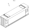
- FIG. 1 is a diagram for illustrating a battery module according to an embodiment of the present disclosure
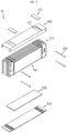
- FIG. 2 is an exploded perspective view showing the battery module of FIG. 1
- FIG. 3 is a diagram for illustrating a battery cell of the battery module of FIG. 2
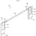
- FIG. 4 is a diagram for illustrating a cell case of the battery module of FIG. 2 .
- a battery module 10 may include a battery cell 100, a cell case 200, a fixing beam 300, a top cover 400, a bottom cover 500, a heat transfer member 600 and a bus bar connecting member 700.
- the battery cell 100 is a secondary battery, which may be a pouch-type secondary battery.
- the battery cell 100 may be provided in plural, and the plurality of battery cells may be stacked on one another and electrically connected to each other.
- Each of the plurality of battery cells 100 may include an electrode assembly 110, a battery case 130, and an electrode lead 150.
- the electrode assembly 110 may include a positive electrode plate, a negative electrode plate and a separator.
- the electrode assembly 110 is well known in the art and thus will not be described in detail.
- the battery case 130 may be made of a laminate sheet including a resin layer and a metal layer and may package the electrode assembly 110.
- the battery case 130 may include a case body 132 and a case terrace 136.
- the case body 132 may accommodate the electrode assembly 110.
- the case body 132 may have an accommodation space formed therein for accommodating the electrode assembly 110.
- the case terrace 136 extends from the case body 132 and may be sealed to package the electrode assembly 110.
- the electrode lead 150 is provided in a pair, and the pair of electrode leads 150 may be composed of a positive electrode lead and a negative electrode lead.
- the pair of electrode leads 150 are electrically connected to the electrode assembly 110 and may protrude out on at least one side of the case terrace 136 of the battery case 130, specifically on both sides of the case terrace 136.
- the cell case 200 may cover both sides and an upper side of the at least one battery cell 100. Specifically, the cell case 200 may be provided in plural, and each cell case 200 may cover both sides and the upper side of each battery cell 100. Specifically, each cell case 200 may cover both sides of the case terrace 136 and an upper side of the battery case 130. The plurality of cell cases 200 may be stacked on one another while fixing the battery cells 100, respectively.
- Each of the plurality of cell cases 200 may include a first case frame 210, a second case frame 230, a third case frame 250 and a pair of bus bars 270, 280.
- the first case frame 210 may cover any one of both sides of the case terrace 136 of the battery cell 100.
- the first case frame 210 may have a bus bar placing groove 212 formed for placing the first bus bar 270, explained later.
- the second case frame 230 may cover the other one of both sides of the case terrace 136 of the battery cell 100.
- the second case frame 230 may have a bus bar placing groove 232 formed for placing the second bus bar 280, explained later.
- the third case frame 250 may be formed with a predetermined length, cover the upper side of the battery case 130, and connect the first case frame 210 and the second case frame 230.
- the pair of bus bars 270, 280 are for electrical connection with the electrode lead 150 of the battery cell 100, and one end 274 thereof is connected to the electrode lead 150 and the other end 276 is exposed at the upper side of the cell case 200.
- the pair of bus bars 270, 280 may be composed of a first bus bar 270 and a second bus bar 280.
- the first bus bar 270 is placed on the first case frame 210 and the third case frame 250 and may be connected to the electrode lead 150 that protrudes at any one of both sides of the case terrace 136 of the battery cell 100.
- the first bus bar 270 may include a body plate 272, a lead connection portion 274 (see FIG. 7 ) and an upper exposed portion 276.
- the body plate 272 may be made of metal material and be placed on the bus bar placing groove 212 of the first case frame 210.
- the lead connection portion 274 extends from one end of the body plate 272 and may be electrically connected to the electrode lead 150 by welding or the like. Specifically, the lead connection portion 274 may be formed to have a step from the body plate 272 and be disposed to contact the electrode lead 150 located at the rear when the body plate 272 is placed at the bus bar placing groove 212. After that, the lead connection portion 274 may be connected to the contacted electrode lead 150 by welding or the like.
- the upper exposed portion 276 extends from the other end of the body plate 272 and may be placed on the third case frame 250.
- the upper exposed portion 276 may be electrically connected to the bus bar connecting member 700, explained later.
- the second bus bar 280 is placed on the second case frame 230 and the third case frame 250 and may be connected to the electrode lead 150 that protrudes at the other one of both sides of the case terrace 136 of the battery cell 100.
- the second bus bar 280 may include a body plate 282, a lead connection portion 284 and an upper exposed portion 286, similar to the first bus bar 270.
- the body plate 282 may also be made of metal material, similar to the body plate 272 of the first bus bar 270, and may be placed on the bus bar placing groove 232 of the second case frame 230.
- the lead connection portion 284 extends from one end of the body plate 282 and may be electrically connected to the electrode lead 150 by welding or the like. Specifically, the lead connection portion 284 may be formed to have a step from the body plate 282 and be disposed to contact the electrode lead 150 located at the rear when the body plate 282 is placed at the bus bar placing groove 232. After that, the lead connection portion 284 may be connected to the contacted electrode lead 150 by welding or the like.
- the upper exposed portion 286 extends from the other end of the body plate 282 and may be placed on the third case frame 250.
- the upper exposed portion 286 may be electrically connected to the bus bar connecting member 700, explained later.
- the fixing beam 300 may be mounted through the plurality of cell cases 200 to fix the plurality of cell cases 200.
- the fixing beam 300 may be provided in plural to improve the fixing force between the plurality of cell cases 200.
- the top cover 400 may cover the upper side of the plurality of cell cases 200.
- the top cover 400 may have a bus bar exposing opening 420 for exposing the other end 276, 286 of the plurality of bus bars 270, 280, namely the upper exposed portions 276, 286.
- the bottom cover 500 covers the lower side of the plurality of cell cases 200 and the lower side of the plurality of battery cells 100 and may support the plurality of cell cases 200 and the plurality of battery cells 100.
- the heat transfer member 600 is provided between the plurality of cell cases 200 and the bottom cover 500 and may transfer the heat of the plurality of battery cells 100 toward the bottom cover 500 more quickly.
- the bus bar connecting member 700 may be electrically connected to the bus bars 270, 280 exposed from the top cover 400. In this embodiment, the bus bar connecting member 700 may be provided for parallel connection.
- bus bar connecting member 700 is provided in a pair such that any one bus bar connecting member 700 may connect the first bus bars 270 to each other and the other bus bar connecting member 700 may connect the second bus bars 280 to each other.
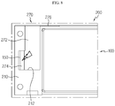
- FIGS. 5 to 8 are diagrams for illustrating a process of assembling the battery cell and the cell case of the battery module of FIG. 2 .
- a worker or the like may dispose the cell case 200 in front of the battery cell 100 and then connect the battery cell 100 and the cell case 200 to each other.
- the first case frame 210 and the second case frame 230 of the cell case 200 may cover the front of both sides of the case terrace 136 of the battery cell 100.
- the battery cell 100 may realize a rectangular form by coupling with the cell case 200. That is, even if the battery cell 100 is the pouch-type secondary battery, since the battery cell 100 may realize a rectangular form by coupling with the cell case 200, a higher capacity may be obtained than in the case where a plurality of battery cells are stacked, and also it may be advantageous in terms of automation and component sharing of the assembling process.
- a worker or the like may weld the lead connection portion 274 of the first bus bar 270 placed on the first case frame 210 and the electrode lead 150 disposed to contact the lead connection portion 274 at the rear of the lead connection portion 274 by laser welding or the like.
- the electrode lead 150 naturally comes into contact with the lead connection portion 274 at the rear of the lead connection portion 274 of the first bus bar 270, and thus the welding process may be performed more conveniently.
- the worker or the like may also weld the electrode lead 150 with the second bus bar 280 placed on the second case frame 230 in a similar manner.
- the worker or the like may stack the plurality of cell cases 200 coupled to the battery cells 100 and then electrically connect the bus bar connecting member 700 and the bus bars 270, 280 at the upper side of the cell cases 200.
- the electrical connection to the bus bar connecting member 700 may be performed more conveniently at the upper side of the battery module 10 via the upper exposed portions 276, 286 of the bus bars 270, 280 exposed at the upper side of the cell case 200.
- one end of the bus bars 270, 280 mounted to the cell case 200 is connected to the electrode lead 150 at the front of the case terrace 136 of the battery cell 100 and the other end is connected to the bus bar connecting member 700 at the upper side of the battery module 10 toward the upper side of the battery module 10.
- the battery module 10 may minimize a dead space that may be generated when electrically connecting the electrode leads 150 of the battery cells 100 through the cell case 200 and the bus bars 270, 280 assembled to the cell case 200.
- the battery module 10 according to this embodiment may further increase the capacity of the battery module 10, and thus it is possible to further improve the energy density of the battery module 10.
- FIG. 9 is a diagram for illustrating a battery module according to another embodiment of the present disclosure.
- the battery module 20 according to this embodiment is similar to the battery module 10 of the former embodiment, and thus different features from the former embodiment will be described in detail.
- the battery module 20 may be connected in series, unlike the former embodiment.
- the battery module 20 may include a bus bar connecting member 800 for serial connection.
- the bus bar connecting member 800 may be formed to have a predetermined length and may be provided in plural.
- the plurality of bus bar connecting members 800 may connect the first bus bar 270 and the second bus bar 280, corresponding to each other, for serial connection.
- the battery module 20 may be connected in series, unlike the former embodiment, and the serial connection may also be performed more conveniently at the upper side of the plurality of cell cases 200 through the plurality of cell cases 200.
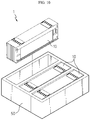
- FIG. 10 is a diagram for illustrating a battery pack according to an embodiment of the present disclosure.
- a battery pack 1 may include at least one battery module 10 according to the former embodiment and a pack case 50 for packaging the at least one battery module 10. Moreover, the battery pack 1 may also include at least one battery module 20 of the former embodiment.
- the battery pack 1 may be provided to a vehicle as a fuel source of the vehicle.
- the battery pack 1 may be provided to an electric vehicle, a hybrid vehicle, and various other-type vehicles capable of using the battery pack 1 as a fuel source.
- the battery pack 1 may be provided in other devices, instruments or facilities such as an energy storage system using a secondary battery, in addition to the vehicle.
- the battery pack 1 of this embodiment and devices, instruments or facilities such as a vehicle, which have the battery pack 1 include the battery module 10 as described above, and thus it is possible to implement a battery pack 1 having all the advantages of the battery module 10 described above, or devices, instruments, facilities or the like such as a vehicle, which have the battery pack 1.
Landscapes
- Chemical & Material Sciences (AREA)
- Chemical Kinetics & Catalysis (AREA)
- Electrochemistry (AREA)
- General Chemical & Material Sciences (AREA)
- Engineering & Computer Science (AREA)
- Manufacturing & Machinery (AREA)
- Battery Mounting, Suspending (AREA)
- Connection Of Batteries Or Terminals (AREA)
- Secondary Cells (AREA)
Abstract
Description
- The present disclosure relates to a battery module, a battery pack including the battery module, and a vehicle including the battery pack.
- The present application claims priority to Korean Patent Application No.
10-2017-0076764 filed on June 16, 2017 - Secondary batteries which are highly applicable to various products and exhibit superior electrical properties such as high energy density, etc. are commonly used not only in portable devices but also in electric vehicles (EVs), hybrid electric vehicles (HEVs), gold carts or the like, driven by electrical power sources. The secondary battery is drawing attentions as a new energy source for enhancing environment friendliness and energy efficiency in that the use of fossil fuels can be reduced greatly and no byproduct is generated during energy consumption.
- Secondary batteries widely used at the preset include lithium ion batteries, lithium polymer batteries, nickel cadmium batteries, nickel hydrogen batteries, nickel zinc batteries and the like. An operating voltage of the unit secondary battery cell, namely a unit battery cell, is about 2.5V to 4.6V. Therefore, if a higher output voltage is required, a plurality of battery cells may be connected in series to configure a battery pack. In addition, depending on the charge/discharge capacity required for the battery pack, a plurality of battery cells may be connected in parallel to configure a battery pack. Thus, the number of battery cells included in the battery pack may be variously set according to the required output voltage or the demanded charge/discharge capacity.
- Meanwhile, when a plurality of battery cells are connected in series or in parallel to configure a battery pack, it is common to configure a battery module composed of at least one battery cell first, and then configure a battery pack by using at least one battery module and adding other components.
- A conventional battery module generally includes a plurality of battery cells electrically connected to each other and a module case accommodating the plurality of battery cells. Here, the electrical connection of the plurality of battery cells is achieved by welding, which is performed after electrode leads of the battery cells are stacked in layers. More specifically, the electrode leads stacked together for welding are partially disposed inside the module case, and the remaining parts are exposed out of the module case for welding. Accordingly, in the conventional battery module, a space is required so that the electrode leads stacked together are partially disposed in the module case for welding.
- However, the space where the electrode leads are partially disposed is a dead space that is independent of the energy density of the battery cells, and thus may deteriorate the capacity of the entire battery module.
- The present disclosure is directed to providing a battery module capable of minimizing a dead space that may be created for electrically connecting electrode leads of battery cells, a battery pack including the battery module, and a vehicle including the battery pack.
- In addition, the present disclosure is directed to providing a battery module capable of improving the energy density by increasing the capacity, a battery pack including the battery module, and a vehicle including the battery pack.
- In one aspect of the present disclosure, there is provided a battery module, comprising: at least one battery cell having electrode leads protruding at both sides thereof; and at least one cell case configured to cover both sides and an upper side of the at least one battery cell and including a pair of bus bars having one end connected to the electrode lead and the other end exposed upwards.
- The at least one battery cell may include: an electrode assembly; a battery case having a case body accommodating the electrode assembly and a case terrace extending from the case body; and the electrode leads protruding at both sides of the case terrace, wherein the cell case covers both sides of the case terrace and an upper side of the battery case.
- The cell case may include: a first case frame and a second case frame configured to cover both sides of the case terrace; and a third case frame configured to cover the upper side of the battery case and connect the first case frame and the second case frame.
- The pair of bus bars may include: a first bus bar placed on the first case frame and the third case frame and connected to the electrode lead; and a second bus bar placed on the second case frame and the third case frame and connected to the electrode lead.
- The first case frame and the second case frame may have a bus bar placing groove at which each bus bar is placed.
- Each of the pair of bus bars may include: a body plate placed at the bus bar placing groove; a lead connection portion extending from one end of the body plate and welded to the electrode lead; and an upper exposed portion extending from the other end of the body plate and placed on the third case frame.
- The lead connection portion may be formed to have a step from the body plate and be disposed to contact the electrode lead when the body plate is placed at the bus bar placing groove.
- The battery cell may be provided in plural and stacked on one another, and the cell case may be provided in plural and stacked on one another while fixing the battery cells, respectively.
- The battery module may further comprise at least one fixing beam mounted through the plurality of cell cases to fix the plurality of cell cases.
- The battery module may further comprise a top cover configured to cover upper sides of the plurality of cell cases and having a bus bar exposing opening that exposes the other end of the plurality of bus bars.
- The battery module may further comprise at least one bus bar connecting member connected to the bus bars exposed from the top cover in series or in parallel.
- The battery module may further comprise a bottom cover configured to cover lower sides of the plurality of cell cases and support the plurality of cell cases.
- The battery module may further comprise a heat transfer member provided between the plurality of cell cases and the bottom cover.
- In another aspect of the present disclosure, there is also provided a battery pack, comprising: at least one battery module according to the above embodiments; and a pack case configured to package the at least one battery module.
- In another aspect of the present disclosure, there is also provided a vehicle, comprising at least one battery pack according to the above embodiments.
- According to various embodiments as above, it is possible to provide a battery module capable of minimizing a dead space that may be created for electrically connecting electrode leads of battery cells, a battery pack including the battery module, and a vehicle including the battery pack.
- In addition, according to various embodiments as above, it is possible to provide a battery module capable of improving the energy density by increasing the capacity, a battery pack including the battery module, and a vehicle including the battery pack.
- The accompanying drawings illustrate a preferred embodiment of the present disclosure and together with the foregoing disclosure, serve to provide further understanding of the technical features of the present disclosure, and thus, the present disclosure is not construed as being limited to the drawing.
-
FIG. 1 is a diagram for illustrating a battery module according to an embodiment of the present disclosure. -
FIG. 2 is an exploded perspective view showing the battery module ofFIG. 1 . -
FIG. 3 is a diagram for illustrating a battery cell of the battery module ofFIG. 2 . -
FIG. 4 is a diagram for illustrating a cell case of the battery module ofFIG. 2 . -
FIGS. 5 to 8 are diagrams for illustrating a process of assembling the battery cell and the cell case of the battery module ofFIG. 2 . -
FIG. 9 is a diagram for illustrating a battery module according to another embodiment of the present disclosure. -
FIG. 10 is a diagram for illustrating a battery pack according to an embodiment of the present disclosure. - The present disclosure will become more apparent by describing in detail the embodiments of the present disclosure with reference to the accompanying drawings. It should be understood that the embodiments disclosed herein are illustrative only for better understanding of the present disclosure, and that the present disclosure may be modified in various ways. In addition, for ease understanding of the present disclosure, the accompanying drawings are not drawn to real scale, but the dimensions of some components may be exaggerated.
-
FIG. 1 is a diagram for illustrating a battery module according to an embodiment of the present disclosure,FIG. 2 is an exploded perspective view showing the battery module ofFIG. 1 ,FIG. 3 is a diagram for illustrating a battery cell of the battery module ofFIG. 2 , andFIG. 4 is a diagram for illustrating a cell case of the battery module ofFIG. 2 . - Referring to
FIGS. 1 to 4 , abattery module 10 may include abattery cell 100, acell case 200, afixing beam 300, atop cover 400, abottom cover 500, aheat transfer member 600 and a busbar connecting member 700. - The
battery cell 100 is a secondary battery, which may be a pouch-type secondary battery. Thebattery cell 100 may be provided in plural, and the plurality of battery cells may be stacked on one another and electrically connected to each other. - Each of the plurality of
battery cells 100 may include anelectrode assembly 110, abattery case 130, and anelectrode lead 150. - The
electrode assembly 110 may include a positive electrode plate, a negative electrode plate and a separator. Theelectrode assembly 110 is well known in the art and thus will not be described in detail. - The
battery case 130 may be made of a laminate sheet including a resin layer and a metal layer and may package theelectrode assembly 110. Thebattery case 130 may include acase body 132 and acase terrace 136. - The
case body 132 may accommodate theelectrode assembly 110. For this, thecase body 132 may have an accommodation space formed therein for accommodating theelectrode assembly 110. Thecase terrace 136 extends from thecase body 132 and may be sealed to package theelectrode assembly 110. - The
electrode lead 150 is provided in a pair, and the pair of electrode leads 150 may be composed of a positive electrode lead and a negative electrode lead. The pair of electrode leads 150 are electrically connected to theelectrode assembly 110 and may protrude out on at least one side of thecase terrace 136 of thebattery case 130, specifically on both sides of thecase terrace 136. - The
cell case 200 may cover both sides and an upper side of the at least onebattery cell 100. Specifically, thecell case 200 may be provided in plural, and eachcell case 200 may cover both sides and the upper side of eachbattery cell 100. Specifically, eachcell case 200 may cover both sides of thecase terrace 136 and an upper side of thebattery case 130. The plurality ofcell cases 200 may be stacked on one another while fixing thebattery cells 100, respectively. - Each of the plurality of
cell cases 200 may include afirst case frame 210, asecond case frame 230, athird case frame 250 and a pair ofbus bars - The
first case frame 210 may cover any one of both sides of thecase terrace 136 of thebattery cell 100. Thefirst case frame 210 may have a busbar placing groove 212 formed for placing thefirst bus bar 270, explained later. - The
second case frame 230 may cover the other one of both sides of thecase terrace 136 of thebattery cell 100. Thesecond case frame 230 may have a busbar placing groove 232 formed for placing thesecond bus bar 280, explained later. - The
third case frame 250 may be formed with a predetermined length, cover the upper side of thebattery case 130, and connect thefirst case frame 210 and thesecond case frame 230. - The pair of
bus bars electrode lead 150 of thebattery cell 100, and oneend 274 thereof is connected to theelectrode lead 150 and theother end 276 is exposed at the upper side of thecell case 200. - Specifically, the pair of
bus bars first bus bar 270 and asecond bus bar 280. - The
first bus bar 270 is placed on thefirst case frame 210 and thethird case frame 250 and may be connected to theelectrode lead 150 that protrudes at any one of both sides of thecase terrace 136 of thebattery cell 100. - The
first bus bar 270 may include abody plate 272, a lead connection portion 274 (seeFIG. 7 ) and an upper exposedportion 276. - The
body plate 272 may be made of metal material and be placed on the busbar placing groove 212 of thefirst case frame 210. - The
lead connection portion 274 extends from one end of thebody plate 272 and may be electrically connected to theelectrode lead 150 by welding or the like. Specifically, thelead connection portion 274 may be formed to have a step from thebody plate 272 and be disposed to contact theelectrode lead 150 located at the rear when thebody plate 272 is placed at the busbar placing groove 212. After that, thelead connection portion 274 may be connected to the contactedelectrode lead 150 by welding or the like. - The upper exposed
portion 276 extends from the other end of thebody plate 272 and may be placed on thethird case frame 250. The upper exposedportion 276 may be electrically connected to the busbar connecting member 700, explained later. - The
second bus bar 280 is placed on thesecond case frame 230 and thethird case frame 250 and may be connected to theelectrode lead 150 that protrudes at the other one of both sides of thecase terrace 136 of thebattery cell 100. - The
second bus bar 280 may include abody plate 282, alead connection portion 284 and an upper exposedportion 286, similar to thefirst bus bar 270. - The
body plate 282 may also be made of metal material, similar to thebody plate 272 of thefirst bus bar 270, and may be placed on the busbar placing groove 232 of thesecond case frame 230. - The
lead connection portion 284 extends from one end of thebody plate 282 and may be electrically connected to theelectrode lead 150 by welding or the like. Specifically, thelead connection portion 284 may be formed to have a step from thebody plate 282 and be disposed to contact theelectrode lead 150 located at the rear when thebody plate 282 is placed at the busbar placing groove 232. After that, thelead connection portion 284 may be connected to the contactedelectrode lead 150 by welding or the like. - The upper exposed
portion 286 extends from the other end of thebody plate 282 and may be placed on thethird case frame 250. The upper exposedportion 286 may be electrically connected to the busbar connecting member 700, explained later. - The
fixing beam 300 may be mounted through the plurality ofcell cases 200 to fix the plurality ofcell cases 200. Thefixing beam 300 may be provided in plural to improve the fixing force between the plurality ofcell cases 200. - The
top cover 400 may cover the upper side of the plurality ofcell cases 200. Thetop cover 400 may have a busbar exposing opening 420 for exposing theother end bus bars portions - The
bottom cover 500 covers the lower side of the plurality ofcell cases 200 and the lower side of the plurality ofbattery cells 100 and may support the plurality ofcell cases 200 and the plurality ofbattery cells 100. - The
heat transfer member 600 is provided between the plurality ofcell cases 200 and thebottom cover 500 and may transfer the heat of the plurality ofbattery cells 100 toward thebottom cover 500 more quickly. - The bus
bar connecting member 700 may be electrically connected to the bus bars 270, 280 exposed from thetop cover 400. In this embodiment, the busbar connecting member 700 may be provided for parallel connection. - Accordingly, the bus
bar connecting member 700 is provided in a pair such that any one busbar connecting member 700 may connect the first bus bars 270 to each other and the other busbar connecting member 700 may connect the second bus bars 280 to each other. - Hereinafter, the assembling process of the
battery module 10 according to this embodiment will be described in more detail. -
FIGS. 5 to 8 are diagrams for illustrating a process of assembling the battery cell and the cell case of the battery module ofFIG. 2 . - Referring to
FIGS. 5 and6 , a worker or the like may dispose thecell case 200 in front of thebattery cell 100 and then connect thebattery cell 100 and thecell case 200 to each other. At this time, thefirst case frame 210 and thesecond case frame 230 of thecell case 200 may cover the front of both sides of thecase terrace 136 of thebattery cell 100. - Accordingly, the
battery cell 100 may realize a rectangular form by coupling with thecell case 200. That is, even if thebattery cell 100 is the pouch-type secondary battery, since thebattery cell 100 may realize a rectangular form by coupling with thecell case 200, a higher capacity may be obtained than in the case where a plurality of battery cells are stacked, and also it may be advantageous in terms of automation and component sharing of the assembling process. - Referring to
FIGS. 7 and8 , after that, a worker or the like may weld thelead connection portion 274 of thefirst bus bar 270 placed on thefirst case frame 210 and theelectrode lead 150 disposed to contact thelead connection portion 274 at the rear of thelead connection portion 274 by laser welding or the like. - As the
battery cell 100 and thecell case 200 are connected, theelectrode lead 150 naturally comes into contact with thelead connection portion 274 at the rear of thelead connection portion 274 of thefirst bus bar 270, and thus the welding process may be performed more conveniently. - The worker or the like may also weld the
electrode lead 150 with thesecond bus bar 280 placed on thesecond case frame 230 in a similar manner. - After that, the worker or the like may stack the plurality of
cell cases 200 coupled to thebattery cells 100 and then electrically connect the busbar connecting member 700 and the bus bars 270, 280 at the upper side of thecell cases 200. - As described above, in this embodiment, the electrical connection to the bus
bar connecting member 700 may be performed more conveniently at the upper side of thebattery module 10 via the upper exposedportions cell case 200. - Also, in this embodiment, one end of the bus bars 270, 280 mounted to the
cell case 200 is connected to theelectrode lead 150 at the front of thecase terrace 136 of thebattery cell 100 and the other end is connected to the busbar connecting member 700 at the upper side of thebattery module 10 toward the upper side of thebattery module 10. Thus, the bending space demanded for connecting the electrode leads 150 of thebattery cells 100 to each other is not needed, thereby minimizing the generation of a dead space in thebattery module 10. - As described above, the
battery module 10 according to this embodiment may minimize a dead space that may be generated when electrically connecting the electrode leads 150 of thebattery cells 100 through thecell case 200 and the bus bars 270, 280 assembled to thecell case 200. - Accordingly, the
battery module 10 according to this embodiment may further increase the capacity of thebattery module 10, and thus it is possible to further improve the energy density of thebattery module 10. -
FIG. 9 is a diagram for illustrating a battery module according to another embodiment of the present disclosure. - The
battery module 20 according to this embodiment is similar to thebattery module 10 of the former embodiment, and thus different features from the former embodiment will be described in detail. - Referring to
FIG. 9 , thebattery module 20 may be connected in series, unlike the former embodiment. For this, thebattery module 20 may include a busbar connecting member 800 for serial connection. - The bus
bar connecting member 800 may be formed to have a predetermined length and may be provided in plural. The plurality of busbar connecting members 800 may connect thefirst bus bar 270 and thesecond bus bar 280, corresponding to each other, for serial connection. - As described above, the
battery module 20 may be connected in series, unlike the former embodiment, and the serial connection may also be performed more conveniently at the upper side of the plurality ofcell cases 200 through the plurality ofcell cases 200. -
FIG. 10 is a diagram for illustrating a battery pack according to an embodiment of the present disclosure. - Referring to
FIG. 10 , a battery pack 1 may include at least onebattery module 10 according to the former embodiment and apack case 50 for packaging the at least onebattery module 10. Moreover, the battery pack 1 may also include at least onebattery module 20 of the former embodiment. - The battery pack 1 may be provided to a vehicle as a fuel source of the vehicle. As an example, the battery pack 1 may be provided to an electric vehicle, a hybrid vehicle, and various other-type vehicles capable of using the battery pack 1 as a fuel source. In addition, the battery pack 1 may be provided in other devices, instruments or facilities such as an energy storage system using a secondary battery, in addition to the vehicle.
- As described above, the battery pack 1 of this embodiment and devices, instruments or facilities such as a vehicle, which have the battery pack 1, include the
battery module 10 as described above, and thus it is possible to implement a battery pack 1 having all the advantages of thebattery module 10 described above, or devices, instruments, facilities or the like such as a vehicle, which have the battery pack 1. - While the embodiments of the present disclosure have been shown and described, it should be understood that the present disclosure is not limited to the specific embodiments described, and that various changes and modifications can be made within the scope of the present disclosure by those skilled in the art, and these modifications should not be understood individually from the technical ideas and views of the present disclosure.
Claims (15)
- A battery module, comprising:at least one battery cell having electrode leads protruding at both sides thereof; andat least one cell case configured to cover both sides and an upper side of the at least one battery cell and including a pair of bus bars having one end connected to the electrode lead and the other end exposed upwards.
- The battery module according to claim 1, wherein the at least one battery cell includes:an electrode assembly;a battery case having a case body accommodating the electrode assembly and a case terrace extending from the case body; andthe electrode leads protruding at both sides of the case terrace,wherein the cell case covers both sides of the case terrace and an upper side of the battery case.
- The battery module according to claim 2, wherein the cell case includes:a first case frame and a second case frame configured to cover both sides of the case terrace; anda third case frame configured to cover the upper side of the battery case and connect the first case frame and the second case frame.
- The battery module according to claim 3, wherein the pair of bus bars include:a first bus bar placed on the first case frame and the third case frame and connected to the electrode lead; anda second bus bar placed on the second case frame and the third case frame and connected to the electrode lead.
- The battery module according to claim 3,
wherein the first case frame and the second case frame have a bus bar placing groove at which each bus bar is placed. - The battery module according to claim 5, wherein each of the pair of bus bars includes:a body plate placed at the bus bar placing groove;a lead connection portion extending from one end of the body plate and welded to the electrode lead; andan upper exposed portion extending from the other end of the body plate and placed on the third case frame.
- The battery module according to claim 6,
wherein the lead connection portion is formed to have a step from the body plate and is disposed to contact the electrode lead when the body plate is placed at the bus bar placing groove. - The battery module according to claim 1,
wherein the battery cell is provided in plural and stacked on one another, and wherein the cell case is provided in plural and stacked on one another while fixing the battery cells, respectively. - The battery module according to claim 8, further comprising:
at least one fixing beam mounted through the plurality of cell cases to fix the plurality of cell cases. - The battery module according to claim 8, further comprising:
a top cover configured to cover upper sides of the plurality of cell cases and having a bus bar exposing opening that exposes the other end of the plurality of bus bars. - The battery module according to claim 10, further comprising:
at least one bus bar connecting member connected to the bus bars exposed from the top cover in series or in parallel. - The battery module according to claim 8, further comprising:
a bottom cover configured to cover lower sides of the plurality of cell cases and support the plurality of cell cases. - The battery module according to claim 12, further comprising:
a heat transfer member provided between the plurality of cell cases and the bottom cover. - A battery pack, comprising:at least one battery module as defined in claim 1; anda pack case configured to package the at least one battery module.
- A vehicle, comprising:
at least one battery pack as defined in claim 14.
Applications Claiming Priority (2)
| Application Number | Priority Date | Filing Date | Title |
|---|---|---|---|
| KR1020170076764A KR102160276B1 (en) | 2017-06-16 | 2017-06-16 | Battery module, battery pack comprising the battery module and vehicle comprising the battery pack |
| PCT/KR2018/003940 WO2018230819A1 (en) | 2017-06-16 | 2018-04-03 | Battery module, battery pack comprising battery module, and vehicle comprising battery pack |
Publications (3)
| Publication Number | Publication Date |
|---|---|
| EP3561902A1 true EP3561902A1 (en) | 2019-10-30 |
| EP3561902A4 EP3561902A4 (en) | 2020-06-17 |
| EP3561902B1 EP3561902B1 (en) | 2024-06-05 |
Family
ID=64659797
Family Applications (1)
| Application Number | Title | Priority Date | Filing Date |
|---|---|---|---|
| EP18818014.5A Active EP3561902B1 (en) | 2017-06-16 | 2018-04-03 | Battery module, battery pack comprising battery module, and vehicle comprising battery pack |
Country Status (8)
| Country | Link |
|---|---|
| US (1) | US11158895B2 (en) |
| EP (1) | EP3561902B1 (en) |
| JP (1) | JP7083831B2 (en) |
| KR (1) | KR102160276B1 (en) |
| CN (1) | CN110178245B (en) |
| HU (1) | HUE066970T2 (en) |
| PL (1) | PL3561902T3 (en) |
| WO (1) | WO2018230819A1 (en) |
Cited By (1)
| Publication number | Priority date | Publication date | Assignee | Title |
|---|---|---|---|---|
| EP4044352A4 (en) * | 2020-08-21 | 2023-08-16 | Lg Energy Solution, Ltd. | Battery module, battery pack including same and method for manufacturing battery pack |
Families Citing this family (8)
| Publication number | Priority date | Publication date | Assignee | Title |
|---|---|---|---|---|
| KR102514123B1 (en) * | 2018-04-19 | 2023-03-23 | 주식회사 엘지에너지솔루션 | A battery module having a bus bar assembly structure that can facilitate welding |
| WO2020180827A1 (en) * | 2019-03-01 | 2020-09-10 | Ted Thomas | Stackable battery bussing system |
| KR102469872B1 (en) | 2019-04-15 | 2022-11-23 | 에스케이온 주식회사 | Battery Module |
| KR20210044099A (en) * | 2019-10-14 | 2021-04-22 | 주식회사 엘지화학 | Battery cell, battery module comprising the battery cell, battery pack comprising the battery module |
| KR20210077971A (en) * | 2019-12-18 | 2021-06-28 | 주식회사 엘지에너지솔루션 | Battery module |
| CN111477828A (en) * | 2020-04-30 | 2020-07-31 | 昆山宝创新能源科技有限公司 | Battery module and have its battery module and car |
| CN111477829A (en) * | 2020-04-30 | 2020-07-31 | 昆山宝创新能源科技有限公司 | Battery module and car |
| CN111477800A (en) * | 2020-04-30 | 2020-07-31 | 昆山宝创新能源科技有限公司 | Battery module, battery pack and vehicle |
Family Cites Families (25)
| Publication number | Priority date | Publication date | Assignee | Title |
|---|---|---|---|---|
| US7989105B2 (en) | 2005-01-21 | 2011-08-02 | Sony Corporation | Battery pack |
| JP4797385B2 (en) | 2005-01-21 | 2011-10-19 | ソニー株式会社 | Battery pack |
| KR100948002B1 (en) * | 2006-03-06 | 2010-03-18 | 주식회사 엘지화학 | Middle or Large-sized Battery Module |
| EP2738838B1 (en) | 2011-07-25 | 2017-11-29 | LG Chem, Ltd. | Battery module having improved reliability and mid-to-large battery pack comprising same |
| KR20130065291A (en) | 2011-12-09 | 2013-06-19 | 삼성에스디아이 주식회사 | Battery pack |
| KR101392799B1 (en) | 2012-06-07 | 2014-05-14 | 주식회사 엘지화학 | Battery Module Having Structure of Improved Stability and High Cooling Efficiency |
| JP2014203763A (en) | 2013-04-09 | 2014-10-27 | 日産自動車株式会社 | Temperature adjustment structure for battery pack |
| US20160043366A1 (en) * | 2013-04-19 | 2016-02-11 | Nec Energy Devices, Ltd. | Battery production method and battery module |
| JP2015022849A (en) * | 2013-07-17 | 2015-02-02 | 三井造船株式会社 | Laminate cell unit, battery module, method for manufacturing laminate cell unit, and method for manufacturing battery module |
| US9748548B2 (en) * | 2013-07-30 | 2017-08-29 | Johnson Controls Technology Company | Pouch frame with integral circuitry for battery module |
| KR101717199B1 (en) * | 2013-08-29 | 2017-03-16 | 주식회사 엘지화학 | Battery Cell Having Connecting Protrusion for Voltage Sensing and Battery Module Comprising the Same |
| KR102030111B1 (en) | 2013-09-04 | 2019-10-08 | 삼성에스디아이 주식회사 | Battery pack |
| KR101688488B1 (en) | 2013-09-17 | 2016-12-21 | 삼성에스디아이 주식회사 | Battery module |
| KR101785538B1 (en) | 2014-07-31 | 2017-10-17 | 주식회사 엘지화학 | Battery module |
| KR101840417B1 (en) * | 2014-09-15 | 2018-03-20 | 주식회사 엘지화학 | Battery Module Comprising Cooling Structure having Minimized Bending of Coolant Channel |
| US9786894B2 (en) * | 2014-11-03 | 2017-10-10 | Lg Chem, Ltd. | Battery pack |
| DE102014225958A1 (en) | 2014-12-16 | 2016-06-16 | Continental Teves Ag & Co. Ohg | Brake system for a motor vehicle |
| KR102317500B1 (en) | 2015-04-29 | 2021-10-26 | 삼성에스디아이 주식회사 | Battery pack |
| KR102058689B1 (en) * | 2015-09-22 | 2019-12-23 | 주식회사 엘지화학 | Battery module, battery pack comprising the battery module and vehicle comprising the battery pack |
| KR101935013B1 (en) | 2015-09-25 | 2019-01-03 | 주식회사 엘지화학 | Battery module, battery pack comprising the battery module and vehicle comprising the battery pack |
| JP6667255B2 (en) * | 2015-10-22 | 2020-03-18 | 株式会社エンビジョンAescジャパン | Battery pack and method of manufacturing battery pack |
| KR102047481B1 (en) * | 2015-10-30 | 2019-11-21 | 주식회사 엘지화학 | Battery module and battery pack including the same |
| KR102032504B1 (en) | 2015-11-06 | 2019-11-08 | 주식회사 엘지화학 | Battery Module improved impact resistance |
| KR102056875B1 (en) | 2015-11-10 | 2019-12-17 | 주식회사 엘지화학 | Battery module and battery pack including the same |
| KR101991925B1 (en) | 2015-12-04 | 2019-06-21 | 주식회사 엘지화학 | Battery Module Comprising Cartridge Having Gripping Part |
-
2017
- 2017-06-16 KR KR1020170076764A patent/KR102160276B1/en active IP Right Grant
-
2018
- 2018-04-03 EP EP18818014.5A patent/EP3561902B1/en active Active
- 2018-04-03 PL PL18818014.5T patent/PL3561902T3/en unknown
- 2018-04-03 CN CN201880006491.7A patent/CN110178245B/en active Active
- 2018-04-03 US US16/464,810 patent/US11158895B2/en active Active
- 2018-04-03 HU HUE18818014A patent/HUE066970T2/en unknown
- 2018-04-03 JP JP2019536970A patent/JP7083831B2/en active Active
- 2018-04-03 WO PCT/KR2018/003940 patent/WO2018230819A1/en unknown
Cited By (1)
| Publication number | Priority date | Publication date | Assignee | Title |
|---|---|---|---|---|
| EP4044352A4 (en) * | 2020-08-21 | 2023-08-16 | Lg Energy Solution, Ltd. | Battery module, battery pack including same and method for manufacturing battery pack |
Also Published As
| Publication number | Publication date |
|---|---|
| EP3561902A4 (en) | 2020-06-17 |
| CN110178245A (en) | 2019-08-27 |
| KR102160276B1 (en) | 2020-09-25 |
| PL3561902T3 (en) | 2024-07-29 |
| JP7083831B2 (en) | 2022-06-13 |
| EP3561902B1 (en) | 2024-06-05 |
| WO2018230819A1 (en) | 2018-12-20 |
| JP2020514980A (en) | 2020-05-21 |
| US11158895B2 (en) | 2021-10-26 |
| CN110178245B (en) | 2022-05-27 |
| US20190348727A1 (en) | 2019-11-14 |
| KR20180137293A (en) | 2018-12-27 |
| HUE066970T2 (en) | 2024-09-28 |
Similar Documents
| Publication | Publication Date | Title |
|---|---|---|
| EP3561902B1 (en) | Battery module, battery pack comprising battery module, and vehicle comprising battery pack | |
| US10603747B2 (en) | Lead welding apparatus, battery module manufactured by the lead welding apparatus, and battery pack comprising the battery module | |
| KR102258817B1 (en) | Battery module, battery pack comprising the battery module and vehicle comprising the battery pack | |
| KR101841801B1 (en) | Battery pack having bushing for coupling end plate | |
| US10625619B2 (en) | Battery module, battery pack comprising battery module, and vehicle comprising battery pack | |
| EP3836244A1 (en) | Battery module and battery pack comprising battery module | |
| US11456502B2 (en) | Battery module, battery pack comprising same battery module, and vehicle comprising same battery pack | |
| EP3799155B1 (en) | Battery module, battery pack comprising battery module, and vehicle comprising battery pack | |
| EP3675223A1 (en) | Battery module, battery pack including same battery module, and automobile including same battery pack | |
| EP3522254B1 (en) | Battery module, battery pack including battery module, and vehicle including battery pack | |
| CN107408651B (en) | Battery module, battery pack including the same, and method of manufacturing case for battery module | |
| KR20150142790A (en) | End plate for battery module assembly thereby preventing a change in the external shape of the battery module due to swelling, and battery pack having the same | |
| KR20150137840A (en) | Unit battery module and Battery module having the same | |
| EP3972039A1 (en) | Cell module assembly and method for manufacturing same | |
| EP4027448A1 (en) | Battery module, battery pack comprising battery module, and vehicle | |
| KR20200063792A (en) | Battery module and method for manufacturing the same |
Legal Events
| Date | Code | Title | Description |
|---|---|---|---|
| STAA | Information on the status of an ep patent application or granted ep patent |
Free format text: STATUS: THE INTERNATIONAL PUBLICATION HAS BEEN MADE |
|
| PUAI | Public reference made under article 153(3) epc to a published international application that has entered the european phase |
Free format text: ORIGINAL CODE: 0009012 |
|
| STAA | Information on the status of an ep patent application or granted ep patent |
Free format text: STATUS: REQUEST FOR EXAMINATION WAS MADE |
|
| 17P | Request for examination filed |
Effective date: 20190724 |
|
| AK | Designated contracting states |
Kind code of ref document: A1 Designated state(s): AL AT BE BG CH CY CZ DE DK EE ES FI FR GB GR HR HU IE IS IT LI LT LU LV MC MK MT NL NO PL PT RO RS SE SI SK SM TR |
|
| AX | Request for extension of the european patent |
Extension state: BA ME |
|
| RIC1 | Information provided on ipc code assigned before grant |
Ipc: H01M 10/6554 20140101ALI20200114BHEP Ipc: H01M 2/10 20060101AFI20200114BHEP Ipc: H01M 2/20 20060101ALI20200114BHEP |
|
| A4 | Supplementary search report drawn up and despatched |
Effective date: 20200520 |
|
| RIC1 | Information provided on ipc code assigned before grant |
Ipc: H01M 2/10 20060101AFI20200514BHEP Ipc: H01M 2/20 20060101ALI20200514BHEP Ipc: H01M 10/6554 20140101ALI20200514BHEP |
|
| DAV | Request for validation of the european patent (deleted) | ||
| DAX | Request for extension of the european patent (deleted) | ||
| RAP1 | Party data changed (applicant data changed or rights of an application transferred) |
Owner name: LG ENERGY SOLUTION LTD. |
|
| RAP3 | Party data changed (applicant data changed or rights of an application transferred) |
Owner name: LG ENERGY SOLUTION, LTD. |
|
| STAA | Information on the status of an ep patent application or granted ep patent |
Free format text: STATUS: EXAMINATION IS IN PROGRESS |
|
| 17Q | First examination report despatched |
Effective date: 20220401 |
|
| REG | Reference to a national code |
Ref country code: DE Ref legal event code: R079 Ref document number: 602018070354 Country of ref document: DE Free format text: PREVIOUS MAIN CLASS: H01M0002100000 Ipc: H01M0050105000 Ref legal event code: R079 Free format text: PREVIOUS MAIN CLASS: H01M0002100000 |
|
| GRAP | Despatch of communication of intention to grant a patent |
Free format text: ORIGINAL CODE: EPIDOSNIGR1 |
|
| STAA | Information on the status of an ep patent application or granted ep patent |
Free format text: STATUS: GRANT OF PATENT IS INTENDED |
|
| RIC1 | Information provided on ipc code assigned before grant |
Ipc: H01M 50/548 20210101ALI20231229BHEP Ipc: H01M 50/516 20210101ALI20231229BHEP Ipc: H01M 50/507 20210101ALI20231229BHEP Ipc: H01M 50/50 20210101ALI20231229BHEP Ipc: H01M 50/211 20210101ALI20231229BHEP Ipc: H01M 10/6554 20140101ALI20231229BHEP Ipc: H01M 50/178 20210101ALI20231229BHEP Ipc: H01M 50/105 20210101AFI20231229BHEP |
|
| RIC1 | Information provided on ipc code assigned before grant |
Ipc: H01M 50/548 20210101ALI20240119BHEP Ipc: H01M 50/516 20210101ALI20240119BHEP Ipc: H01M 50/507 20210101ALI20240119BHEP Ipc: H01M 50/211 20210101ALI20240119BHEP Ipc: H01M 10/6554 20140101ALI20240119BHEP Ipc: H01M 50/178 20210101ALI20240119BHEP Ipc: H01M 50/105 20210101AFI20240119BHEP |
|
| INTG | Intention to grant announced |
Effective date: 20240205 |
|
| GRAS | Grant fee paid |
Free format text: ORIGINAL CODE: EPIDOSNIGR3 |
|
| GRAA | (expected) grant |
Free format text: ORIGINAL CODE: 0009210 |
|
| STAA | Information on the status of an ep patent application or granted ep patent |
Free format text: STATUS: THE PATENT HAS BEEN GRANTED |
|
| AK | Designated contracting states |
Kind code of ref document: B1 Designated state(s): AL AT BE BG CH CY CZ DE DK EE ES FI FR GB GR HR HU IE IS IT LI LT LU LV MC MK MT NL NO PL PT RO RS SE SI SK SM TR |
|
| REG | Reference to a national code |
Ref country code: CH Ref legal event code: EP |
|
| P01 | Opt-out of the competence of the unified patent court (upc) registered |
Effective date: 20240510 |
|
| REG | Reference to a national code |
Ref country code: DE Ref legal event code: R096 Ref document number: 602018070354 Country of ref document: DE |
|
| REG | Reference to a national code |
Ref country code: IE Ref legal event code: FG4D |
|
| REG | Reference to a national code |
Ref country code: SE Ref legal event code: TRGR |
|
| REG | Reference to a national code |
Ref country code: LT Ref legal event code: MG9D |
|
| REG | Reference to a national code |
Ref country code: HU Ref legal event code: AG4A Ref document number: E066970 Country of ref document: HU |