EP3972039A1 - Cell module assembly and method for manufacturing same - Google Patents
Cell module assembly and method for manufacturing same Download PDFInfo
- Publication number
- EP3972039A1 EP3972039A1 EP21744058.5A EP21744058A EP3972039A1 EP 3972039 A1 EP3972039 A1 EP 3972039A1 EP 21744058 A EP21744058 A EP 21744058A EP 3972039 A1 EP3972039 A1 EP 3972039A1
- Authority
- EP
- European Patent Office
- Prior art keywords
- case
- busbar
- battery cells
- cell module
- module assembly
- Prior art date
- Legal status (The legal status is an assumption and is not a legal conclusion. Google has not performed a legal analysis and makes no representation as to the accuracy of the status listed.)
- Pending
Links
Images


Classifications
-
- H—ELECTRICITY
- H01—ELECTRIC ELEMENTS
- H01M—PROCESSES OR MEANS, e.g. BATTERIES, FOR THE DIRECT CONVERSION OF CHEMICAL ENERGY INTO ELECTRICAL ENERGY
- H01M50/00—Constructional details or processes of manufacture of the non-active parts of electrochemical cells other than fuel cells, e.g. hybrid cells
- H01M50/20—Mountings; Secondary casings or frames; Racks, modules or packs; Suspension devices; Shock absorbers; Transport or carrying devices; Holders
-
- H—ELECTRICITY
- H01—ELECTRIC ELEMENTS
- H01M—PROCESSES OR MEANS, e.g. BATTERIES, FOR THE DIRECT CONVERSION OF CHEMICAL ENERGY INTO ELECTRICAL ENERGY
- H01M10/00—Secondary cells; Manufacture thereof
- H01M10/60—Heating or cooling; Temperature control
- H01M10/61—Types of temperature control
- H01M10/613—Cooling or keeping cold
-
- H—ELECTRICITY
- H01—ELECTRIC ELEMENTS
- H01M—PROCESSES OR MEANS, e.g. BATTERIES, FOR THE DIRECT CONVERSION OF CHEMICAL ENERGY INTO ELECTRICAL ENERGY
- H01M10/00—Secondary cells; Manufacture thereof
- H01M10/60—Heating or cooling; Temperature control
- H01M10/65—Means for temperature control structurally associated with the cells
- H01M10/655—Solid structures for heat exchange or heat conduction
- H01M10/6551—Surfaces specially adapted for heat dissipation or radiation, e.g. fins or coatings
-
- H—ELECTRICITY
- H01—ELECTRIC ELEMENTS
- H01M—PROCESSES OR MEANS, e.g. BATTERIES, FOR THE DIRECT CONVERSION OF CHEMICAL ENERGY INTO ELECTRICAL ENERGY
- H01M50/00—Constructional details or processes of manufacture of the non-active parts of electrochemical cells other than fuel cells, e.g. hybrid cells
- H01M50/20—Mountings; Secondary casings or frames; Racks, modules or packs; Suspension devices; Shock absorbers; Transport or carrying devices; Holders
- H01M50/204—Racks, modules or packs for multiple batteries or multiple cells
- H01M50/207—Racks, modules or packs for multiple batteries or multiple cells characterised by their shape
- H01M50/209—Racks, modules or packs for multiple batteries or multiple cells characterised by their shape adapted for prismatic or rectangular cells
-
- H—ELECTRICITY
- H01—ELECTRIC ELEMENTS
- H01M—PROCESSES OR MEANS, e.g. BATTERIES, FOR THE DIRECT CONVERSION OF CHEMICAL ENERGY INTO ELECTRICAL ENERGY
- H01M50/00—Constructional details or processes of manufacture of the non-active parts of electrochemical cells other than fuel cells, e.g. hybrid cells
- H01M50/20—Mountings; Secondary casings or frames; Racks, modules or packs; Suspension devices; Shock absorbers; Transport or carrying devices; Holders
- H01M50/244—Secondary casings; Racks; Suspension devices; Carrying devices; Holders characterised by their mounting method
-
- H—ELECTRICITY
- H01—ELECTRIC ELEMENTS
- H01M—PROCESSES OR MEANS, e.g. BATTERIES, FOR THE DIRECT CONVERSION OF CHEMICAL ENERGY INTO ELECTRICAL ENERGY
- H01M50/00—Constructional details or processes of manufacture of the non-active parts of electrochemical cells other than fuel cells, e.g. hybrid cells
- H01M50/20—Mountings; Secondary casings or frames; Racks, modules or packs; Suspension devices; Shock absorbers; Transport or carrying devices; Holders
- H01M50/258—Modular batteries; Casings provided with means for assembling
-
- H—ELECTRICITY
- H01—ELECTRIC ELEMENTS
- H01M—PROCESSES OR MEANS, e.g. BATTERIES, FOR THE DIRECT CONVERSION OF CHEMICAL ENERGY INTO ELECTRICAL ENERGY
- H01M50/00—Constructional details or processes of manufacture of the non-active parts of electrochemical cells other than fuel cells, e.g. hybrid cells
- H01M50/20—Mountings; Secondary casings or frames; Racks, modules or packs; Suspension devices; Shock absorbers; Transport or carrying devices; Holders
- H01M50/262—Mountings; Secondary casings or frames; Racks, modules or packs; Suspension devices; Shock absorbers; Transport or carrying devices; Holders with fastening means, e.g. locks
-
- H—ELECTRICITY
- H01—ELECTRIC ELEMENTS
- H01M—PROCESSES OR MEANS, e.g. BATTERIES, FOR THE DIRECT CONVERSION OF CHEMICAL ENERGY INTO ELECTRICAL ENERGY
- H01M50/00—Constructional details or processes of manufacture of the non-active parts of electrochemical cells other than fuel cells, e.g. hybrid cells
- H01M50/20—Mountings; Secondary casings or frames; Racks, modules or packs; Suspension devices; Shock absorbers; Transport or carrying devices; Holders
- H01M50/271—Lids or covers for the racks or secondary casings
-
- H—ELECTRICITY
- H01—ELECTRIC ELEMENTS
- H01M—PROCESSES OR MEANS, e.g. BATTERIES, FOR THE DIRECT CONVERSION OF CHEMICAL ENERGY INTO ELECTRICAL ENERGY
- H01M50/00—Constructional details or processes of manufacture of the non-active parts of electrochemical cells other than fuel cells, e.g. hybrid cells
- H01M50/50—Current conducting connections for cells or batteries
- H01M50/502—Interconnectors for connecting terminals of adjacent batteries; Interconnectors for connecting cells outside a battery casing
- H01M50/503—Interconnectors for connecting terminals of adjacent batteries; Interconnectors for connecting cells outside a battery casing characterised by the shape of the interconnectors
-
- H—ELECTRICITY
- H01—ELECTRIC ELEMENTS
- H01M—PROCESSES OR MEANS, e.g. BATTERIES, FOR THE DIRECT CONVERSION OF CHEMICAL ENERGY INTO ELECTRICAL ENERGY
- H01M50/00—Constructional details or processes of manufacture of the non-active parts of electrochemical cells other than fuel cells, e.g. hybrid cells
- H01M50/50—Current conducting connections for cells or batteries
- H01M50/502—Interconnectors for connecting terminals of adjacent batteries; Interconnectors for connecting cells outside a battery casing
- H01M50/507—Interconnectors for connecting terminals of adjacent batteries; Interconnectors for connecting cells outside a battery casing comprising an arrangement of two or more busbars within a container structure, e.g. busbar modules
-
- H—ELECTRICITY
- H01—ELECTRIC ELEMENTS
- H01M—PROCESSES OR MEANS, e.g. BATTERIES, FOR THE DIRECT CONVERSION OF CHEMICAL ENERGY INTO ELECTRICAL ENERGY
- H01M50/00—Constructional details or processes of manufacture of the non-active parts of electrochemical cells other than fuel cells, e.g. hybrid cells
- H01M50/50—Current conducting connections for cells or batteries
- H01M50/531—Electrode connections inside a battery casing
- H01M50/533—Electrode connections inside a battery casing characterised by the shape of the leads or tabs
-
- H—ELECTRICITY
- H01—ELECTRIC ELEMENTS
- H01M—PROCESSES OR MEANS, e.g. BATTERIES, FOR THE DIRECT CONVERSION OF CHEMICAL ENERGY INTO ELECTRICAL ENERGY
- H01M2220/00—Batteries for particular applications
- H01M2220/10—Batteries in stationary systems, e.g. emergency power source in plant
-
- H—ELECTRICITY
- H01—ELECTRIC ELEMENTS
- H01M—PROCESSES OR MEANS, e.g. BATTERIES, FOR THE DIRECT CONVERSION OF CHEMICAL ENERGY INTO ELECTRICAL ENERGY
- H01M2220/00—Batteries for particular applications
- H01M2220/20—Batteries in motive systems, e.g. vehicle, ship, plane
-
- Y—GENERAL TAGGING OF NEW TECHNOLOGICAL DEVELOPMENTS; GENERAL TAGGING OF CROSS-SECTIONAL TECHNOLOGIES SPANNING OVER SEVERAL SECTIONS OF THE IPC; TECHNICAL SUBJECTS COVERED BY FORMER USPC CROSS-REFERENCE ART COLLECTIONS [XRACs] AND DIGESTS
- Y02—TECHNOLOGIES OR APPLICATIONS FOR MITIGATION OR ADAPTATION AGAINST CLIMATE CHANGE
- Y02E—REDUCTION OF GREENHOUSE GAS [GHG] EMISSIONS, RELATED TO ENERGY GENERATION, TRANSMISSION OR DISTRIBUTION
- Y02E60/00—Enabling technologies; Technologies with a potential or indirect contribution to GHG emissions mitigation
- Y02E60/10—Energy storage using batteries
Definitions
- the present invention relates to a cell module assembly formed by receiving a battery cell in a case having a busbar unit integrally coupled thereto.
- secondary batteries which are energy sources substituting for fossil fuels causing air pollution, have been applied to an electric vehicle (EV), a hybrid electric vehicle (HEV), a plug-in hybrid electric vehicle (P-HEV), and an energy storage system (ESS).
- EV electric vehicle
- HEV hybrid electric vehicle
- P-HEV plug-in hybrid electric vehicle
- ESS energy storage system
- the energy storage system is a system that stores a large amount of excess power in a battery in order to use the stored power when needed.
- the energy storage system serves to uniformly maintain quality of power in connection with new and renewable energy generation and to increase efficiency in use of power by storing power at the time when the amount of use of power is small and using the stored power when the demand for power is high.
- the ESS may mainly be classified as a grid system ESS, an uninterruptible power supply (UPS), or an ESS for domestic use.
- UPS uninterruptible power supply
- a lithium ion battery a lithium polymer battery, a nickel-cadmium battery, a nickel-hydride battery, and a nickel-zinc battery as secondary batteries that are widely used at present.
- the operating voltage of a unit secondary battery cell i.e. a unit battery cell, is about 2.0V to 5.0V.
- a plurality of battery cells may be connected to each other in series to constitute a cell module assembly.
- cell module assemblies may be connected to each other in series or in parallel to constitute a battery module depending on required output voltage or charge and discharge capacities.
- a battery pack is manufactured using at least one battery module by adding an additional component.
- Battery cells 10, each of which has electrode leads 11, and cartridges 20 are alternately disposed between end covers 40 located at the outer sides of the cell module assembly, and a busbar unit 30, configured to be electrically connected to the electrode leads 11, is coupled to the front and the rear of the battery cells 10, from which the electrode leads 11 protrude, whereby the cell module assembly 1 is formed.
- the present invention has been made in view of the above problems, and it is an object of the present invention to provide a cell module assembly having a battery cell received in a case to which a busbar unit including a busbar frame, one side of which is bent so as to receive the battery cell, is coupled.
- a cell module assembly includes a plurality of battery cells, each of the battery cells having electrode leads, a case configured to receive the battery cells, a cover plate located at an open upper surface of the case so as to be coupled to the case, and a busbar unit located at the front and the rear of the case, from which the electrode leads of the received battery cells protrude, wherein the case is configured to have a U shape in which a base plate defining the bottom surface of the case and side plates defining opposite side surfaces of the case are coupled to each other.
- the case and the busbar unit may be integrally coupled to each other before the battery cells are received in the case.
- the busbar unit may include a busbar body having formed therein slits, through which the electrode leads are inserted, and a busbar frame coupled to the busbar body, the busbar frame being joined to the electrode leads inserted into the busbar unit.
- the busbar frame may be provided with slits, through which the electrode leads are inserted, formed at positions corresponding to the slits formed in the busbar body, one end of the busbar frame being bent to the outside of the case.
- side walls extending perpendicularly from the base plate may be formed in the case, the side walls being configured to guide positions of the battery cells received in the case.
- the side walls may be cooling fins configured to dissipate heat generated from the battery cells.
- the case and the cover plate may be coupled to each other by mechanical fastening.
- a method of manufacturing a cell module assembly includes coupling a base plate defining a bottom surface and side plates defining opposite side surfaces to each other to form a U-shaped case configured to receive a plurality of battery cells, each of the battery cells having electrode leads, coupling a busbar unit to the front and the rear of the case, from which the electrode leads protrude, receiving the battery cells in the case having the busbar unit coupled thereto, and locating a cover plate at the upper part of the case having the battery cells received therein and coupling the cover plate to the side plates of the case.
- the busbar unit may include a busbar body having formed therein slits, through which the electrode leads are inserted, and a busbar frame coupled to the busbar body, the busbar frame being joined to the electrode leads inserted into the busbar unit.
- the busbar frame may be provided with slits, through which the electrode leads are inserted, formed at positions corresponding to the slits formed in the busbar body, one end of the busbar frame being bent to the outside of the case.
- the case and the cover plate may be coupled to each other by mechanical fastening.
- the method of manufacturing the cell module assembly according to the present invention may further include forming side walls extending perpendicularly from the base plate before the step of receiving the battery cells, the side walls being configured to guide positions of the battery cells received in the case.
- a battery module according to the present invention includes at least one cell module assembly according to the present invention.
- a device includes at least one battery module according to the present invention.
- a cell module assembly according to the present invention has an advantage in that battery cells are received in a case having a busbar unit integrally coupled thereto, whereby it is possible to reduce time required for an assembly process, compared to a conventional structure in which battery cells and cartridges are sequentially stacked.
- the cell module assembly according to the present invention has an advantage in that one side of the busbar unit coupled to the case is bent to the outside of the case, whereby it is possible to easily receive and remove the battery cells.
- the cell module assembly according to the present invention has an advantage in that only a cover plate at the upper part of the case is separated from the cell module assembly, whereby it is possible to easily perform the inspection of external appearance of the battery cells and the measurement of insulation voltage of the battery cells.
- FIG. 2 is a schematic view of a cell module assembly according to a first preferred embodiment of the present invention.
- the cell module assembly 1000 will be described with reference to FIG. 2 .
- the cell module assembly 1000 includes a plurality of battery cells 10, each of which has electrode leads 11, a case 100 configured to receive the battery cells, a cover plate 200 located at the upper part of the case 100 so as to be coupled to the case, and a busbar unit 300 located at the front and the rear of the case, from which the electrode leads 11 protrude, so as to be electrically connected to the electrode leads.
- side walls 130 extending perpendicularly from the lower part of the case 100 in order to guide the positions of the battery cells 10 received in the case may be formed in the case 100.
- Each of the side walls 130 may have a size that covers only a portion of each of opposite ends of a corresponding one of the battery cells 10 received in the case. Depending on circumstances, each of the side walls may have a size that covers the entirety of a corresponding one of the battery cells 10 received in the case.
- cooling fins may be used to discharge heat generated from the battery cells 10 to the side walls 130.
- Each of the battery cells used in the cell module assembly 1000 according to the present invention may be constituted by a secondary battery.
- the secondary battery may be generally classified as a pouch-shaped secondary battery, a cylindrical secondary battery, or a prismatic secondary battery.
- a pouch-shaped secondary battery is used as the battery cell according to the present invention.
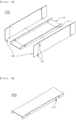
- the case 100 includes a base plate 110 located at the lower part thereof and side plates 120 located at opposite side surfaces thereof.
- the base plate 110 and the side plates 120 are provided with fastening portions 111 and 121 for coupling between adjacent plates.
- the cover plate 200 is also provided with fastening portions 211 for coupling with the case 100. Coupling between the base plate 110 and the side plates 120 and coupling between the side plates 120 and the cover plate 200 are performed through the fastening portions 111, 121, and 211.
- Any of various known methods, such as mechanical fastening using bolts or welding, may be used as such a fastening method.
- fastening between the side plates 120 and the cover plate 200 be performed by mechanical fastening such that disassembly and fastening therebetween are easily performed even after the battery cells 10 are received in the case 100.
- the busbar unit 300 includes a busbar body 310 including slits 330, in which the electrode leads 11 are located, and a busbar frame 320 coupled to the busbar body 310, the busbar frame being provided with slits 330, in which the electrode leads 11 may be received, formed at positions corresponding to the slits 330 of the busbar body.
- the busbar frame 320 is provided with fastening portions 321 for assembly with the busbar body, and fastening portions (not shown) corresponding thereto may also be formed at the busbar body 310.
- the busbar frame 320 includes a bent portion 322 bent from one side thereof to the outside of the case so as not to interfere with the electrode lead 11 of the battery cell 10 received in the case.
- a busbar frame 320 from which the bent portion is bent so as to have a bending angle perpendicular thereto, is shown; however, this is merely one of possible examples. The bending angle may be changed within a range within which there is no interference between the electrode lead 11 and the busbar frame 320 when the battery cell 10 is inserted into the case 100.
- the bent portion 322 is formed at the portion of the busbar frame 320, at which the electrode lead 11 starts to be received.
- the battery cells 10 can be easily received in the case 100 even after the busbar unit 300 is first coupled to the case, unlike the conventional cell module assembly, in which the busbar unit is coupled after the battery cells 10 and the cartridges are stacked. Since the busbar unit 300 is assembled to the case 100 in advance, as described above, it is possible to simplify a process of manufacturing the cell module assembly and in addition to shorten a process time. Any of various known methods, such as mechanical fastening using bolts or welding, may be used as a method of assembling the busbar unit 300 to the case 100.
- battery cells 10 are received in a case 100 having a busbar unit 300 coupled thereto, and electrode leads 11 of the battery cells 10 received in the case are joined to a busbar frame 320 such that the electrode leads 11 are electrically connected to the busbar unit 300.
- a known electrode lead joining method such as welding, may be used as a joining method.
- a cover plate 200 is located at the upper part of the battery cells 10 received in the case, and the cover plate 200 is fastened to side plates 120 to manufacture a cell module assembly 1000, as shown in the right figure.
- a process of forming side walls 130 extending perpendicularly from a base plate 110, the side walls being configured to guide the positions of the battery cells 10 received in the case 100, before the battery cells 10 are received in the case may be included.
- Each of the side walls 130 may be formed so as to have any of various sizes within a range of size of an inner space of the case 100 in which the battery cells 10 are received.
- the cover plate 200 at the upper part of the case may be separated from the cell module assembly 1000 according to the present invention manufactured as described above, whereby the inspection of external appearance of the battery cells 10 and the measurement of insulation voltage of the battery cells may be easily performed.
- the battery module may include an external connection terminal configured to connect at least one cell module assembly 1000 to an external electric device and a heat sink configured to dissipate heat generated from the battery cells.
- one or more battery modules may be connected to each other using an electrical connection method in order to constitute a battery pack.
- the battery pack may be applied to an electric vehicle (EV), a hybrid electric vehicle (HEV), a plug-in hybrid electric vehicle (P-HEV), or an energy storage system (ESS).
- EV electric vehicle
- HEV hybrid electric vehicle
- P-HEV plug-in hybrid electric vehicle
- ESS energy storage system
Abstract
Description
- This application claims the benefit of priority to
Korean Patent Application No. 2020-0008052 filed on January 21, 2020 - The present invention relates to a cell module assembly formed by receiving a battery cell in a case having a busbar unit integrally coupled thereto.
- With technological development of mobile devices, such as mobile phones, laptop computers, camcorders, and digital cameras, and an increase in demand therefor, technologies related to secondary batteries, which are capable of being charged and discharged, have been active. In addition, secondary batteries, which are energy sources substituting for fossil fuels causing air pollution, have been applied to an electric vehicle (EV), a hybrid electric vehicle (HEV), a plug-in hybrid electric vehicle (P-HEV), and an energy storage system (ESS).
- The energy storage system (ESS) is a system that stores a large amount of excess power in a battery in order to use the stored power when needed. The energy storage system serves to uniformly maintain quality of power in connection with new and renewable energy generation and to increase efficiency in use of power by storing power at the time when the amount of use of power is small and using the stored power when the demand for power is high. The ESS may mainly be classified as a grid system ESS, an uninterruptible power supply (UPS), or an ESS for domestic use.
- There are a lithium ion battery, a lithium polymer battery, a nickel-cadmium battery, a nickel-hydride battery, and a nickel-zinc battery as secondary batteries that are widely used at present. The operating voltage of a unit secondary battery cell, i.e. a unit battery cell, is about 2.0V to 5.0V. In the case in which output voltage higher than the above operating voltage is required, therefore, a plurality of battery cells may be connected to each other in series to constitute a cell module assembly. In addition, cell module assemblies may be connected to each other in series or in parallel to constitute a battery module depending on required output voltage or charge and discharge capacities. In general, a battery pack is manufactured using at least one battery module by adding an additional component.
- Meanwhile, a conventional
cell module assembly 1 will be described with reference toFIG. 1 .Battery cells 10, each of which has electrode leads 11, andcartridges 20 are alternately disposed between end covers 40 located at the outer sides of the cell module assembly, and abusbar unit 30, configured to be electrically connected to the electrode leads 11, is coupled to the front and the rear of thebattery cells 10, from which the electrode leads 11 protrude, whereby thecell module assembly 1 is formed. - In such a cell module assembly, however, it is necessary to perform a complicated process of alternately stacking the end covers 40, the
battery cells 10, and thecartridges 20 so as to be assembled and coupling thebusbar unit 30 to the stack. Furthermore, when the cell module assembly is wrongly assembled, it takes considerable time to reassemble the cell module assembly. - The present invention has been made in view of the above problems, and it is an object of the present invention to provide a cell module assembly having a battery cell received in a case to which a busbar unit including a busbar frame, one side of which is bent so as to receive the battery cell, is coupled.
- In order to accomplish the above object, a cell module assembly according to the present invention includes a plurality of battery cells, each of the battery cells having electrode leads, a case configured to receive the battery cells, a cover plate located at an open upper surface of the case so as to be coupled to the case, and a busbar unit located at the front and the rear of the case, from which the electrode leads of the received battery cells protrude, wherein the case is configured to have a U shape in which a base plate defining the bottom surface of the case and side plates defining opposite side surfaces of the case are coupled to each other.
- Also, in the cell module assembly according to the present invention, the case and the busbar unit may be integrally coupled to each other before the battery cells are received in the case.
- Also, in the cell module assembly according to the present invention, the busbar unit may include a busbar body having formed therein slits, through which the electrode leads are inserted, and a busbar frame coupled to the busbar body, the busbar frame being joined to the electrode leads inserted into the busbar unit.
- Also, in the cell module assembly according to the present invention, the busbar frame may be provided with slits, through which the electrode leads are inserted, formed at positions corresponding to the slits formed in the busbar body, one end of the busbar frame being bent to the outside of the case.
- Also, in the cell module assembly according to the present invention, side walls extending perpendicularly from the base plate may be formed in the case, the side walls being configured to guide positions of the battery cells received in the case.
- Also, in the cell module assembly according to the present invention, the side walls may be cooling fins configured to dissipate heat generated from the battery cells.
- Also, in the cell module assembly according to the present invention, the case and the cover plate may be coupled to each other by mechanical fastening.
- In addition, a method of manufacturing a cell module assembly according to the present invention includes coupling a base plate defining a bottom surface and side plates defining opposite side surfaces to each other to form a U-shaped case configured to receive a plurality of battery cells, each of the battery cells having electrode leads,
coupling a busbar unit to the front and the rear of the case, from which the electrode leads protrude, receiving the battery cells in the case having the busbar unit coupled thereto, and locating a cover plate at the upper part of the case having the battery cells received therein and coupling the cover plate to the side plates of the case. - Also, in the method of manufacturing the cell module assembly according to the present invention, the busbar unit may include a busbar body having formed therein slits, through which the electrode leads are inserted, and a busbar frame coupled to the busbar body, the busbar frame being joined to the electrode leads inserted into the busbar unit.
- Also, in the method of manufacturing the cell module assembly according to the present invention, the busbar frame may be provided with slits, through which the electrode leads are inserted, formed at positions corresponding to the slits formed in the busbar body, one end of the busbar frame being bent to the outside of the case.
- Also, in the method of manufacturing the cell module assembly according to the present invention, the case and the cover plate may be coupled to each other by mechanical fastening.
- Also, the method of manufacturing the cell module assembly according to the present invention may further include forming side walls extending perpendicularly from the base plate before the step of receiving the battery cells, the side walls being configured to guide positions of the battery cells received in the case.
- In addition, a battery module according to the present invention includes at least one cell module assembly according to the present invention.
- In addition, a device according to the present invention includes at least one battery module according to the present invention.
- A cell module assembly according to the present invention has an advantage in that battery cells are received in a case having a busbar unit integrally coupled thereto, whereby it is possible to reduce time required for an assembly process, compared to a conventional structure in which battery cells and cartridges are sequentially stacked.
- In addition, the cell module assembly according to the present invention has an advantage in that one side of the busbar unit coupled to the case is bent to the outside of the case, whereby it is possible to easily receive and remove the battery cells.
- In addition, the cell module assembly according to the present invention has an advantage in that only a cover plate at the upper part of the case is separated from the cell module assembly, whereby it is possible to easily perform the inspection of external appearance of the battery cells and the measurement of insulation voltage of the battery cells.
-
-
FIG. 1 is an exploded perspective view of a conventional cell module assembly. -
FIG. 2 is a schematic view of a cell module assembly according to the present invention. -
FIG. 3 is an exploded perspective view of a case according to the present invention. -
FIG. 4 is a schematic view of a cover plate according to the present invention. -
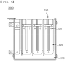
FIG. 5 is a schematic view showing the front shape of a busbar unit according to the present invention. -
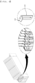
FIG. 6 is a detailed view of the busbar unit according to the present invention. -
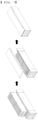
FIG. 7 is a schematic view showing a method of manufacturing a cell module assembly according to the present invention. - In the present application, it should be understood that the terms "comprises," "has," "includes," etc. specify the presence of stated features, numbers, steps, operations, elements, components, or combinations thereof, but do not preclude the presence or addition of one or more other features, numbers, steps, operations, elements, components, or combinations thereof.
- In addition, the same reference numbers will be used throughout the drawings to refer to parts that perform similar functions or operations. In the case in which one part is said to be connected to another part in the specification, not only may the one part be directly connected to the other part, but also, the one part may be indirectly connected to the other part via a further part. In addition, that a certain element is included does not mean that other elements are excluded, but means that such elements may be further included unless mentioned otherwise.
- Hereinafter, a cell module assembly according to the present invention will be described with reference to the accompanying drawings.
-
FIG. 2 is a schematic view of a cell module assembly according to a first preferred embodiment of the present invention. - The
cell module assembly 1000 will be described with reference toFIG. 2 . Thecell module assembly 1000 according to the present invention includes a plurality ofbattery cells 10, each of which has electrode leads 11, acase 100 configured to receive the battery cells, acover plate 200 located at the upper part of thecase 100 so as to be coupled to the case, and abusbar unit 300 located at the front and the rear of the case, from which the electrode leads 11 protrude, so as to be electrically connected to the electrode leads. In addition,side walls 130 extending perpendicularly from the lower part of thecase 100 in order to guide the positions of thebattery cells 10 received in the case may be formed in thecase 100. Each of theside walls 130 may have a size that covers only a portion of each of opposite ends of a corresponding one of thebattery cells 10 received in the case. Depending on circumstances, each of the side walls may have a size that covers the entirety of a corresponding one of thebattery cells 10 received in the case. In addition, cooling fins may be used to discharge heat generated from thebattery cells 10 to theside walls 130. - Each of the battery cells used in the
cell module assembly 1000 according to the present invention may be constituted by a secondary battery. Based on the kind and shape of a sheathing member, the secondary battery may be generally classified as a pouch-shaped secondary battery, a cylindrical secondary battery, or a prismatic secondary battery. Preferably, a pouch-shaped secondary battery is used as the battery cell according to the present invention. - Meanwhile, the
case 100 and thecover plate 200 will be described in detail with reference toFIGS. 3 and 4 . Thecase 100 includes abase plate 110 located at the lower part thereof andside plates 120 located at opposite side surfaces thereof. Thebase plate 110 and theside plates 120 are provided withfastening portions cover plate 200 is also provided withfastening portions 211 for coupling with thecase 100. Coupling between thebase plate 110 and theside plates 120 and coupling between theside plates 120 and thecover plate 200 are performed through thefastening portions side plates 120 and thecover plate 200 be performed by mechanical fastening such that disassembly and fastening therebetween are easily performed even after thebattery cells 10 are received in thecase 100. - In addition, the
busbar unit 300 will be described with reference toFIGS. 5 and6 . Thebusbar unit 300 includes abusbar body 310 includingslits 330, in which the electrode leads 11 are located, and abusbar frame 320 coupled to thebusbar body 310, the busbar frame being provided withslits 330, in which the electrode leads 11 may be received, formed at positions corresponding to theslits 330 of the busbar body. Thebusbar frame 320 is provided withfastening portions 321 for assembly with the busbar body, and fastening portions (not shown) corresponding thereto may also be formed at thebusbar body 310. - In addition, the
busbar frame 320 includes abent portion 322 bent from one side thereof to the outside of the case so as not to interfere with theelectrode lead 11 of thebattery cell 10 received in the case. In the figures, abusbar frame 320, from which the bent portion is bent so as to have a bending angle perpendicular thereto, is shown; however, this is merely one of possible examples. The bending angle may be changed within a range within which there is no interference between theelectrode lead 11 and thebusbar frame 320 when thebattery cell 10 is inserted into thecase 100. - As described above, the
bent portion 322 is formed at the portion of thebusbar frame 320, at which theelectrode lead 11 starts to be received. In the present invention, therefore, thebattery cells 10 can be easily received in thecase 100 even after thebusbar unit 300 is first coupled to the case, unlike the conventional cell module assembly, in which the busbar unit is coupled after thebattery cells 10 and the cartridges are stacked. Since thebusbar unit 300 is assembled to thecase 100 in advance, as described above, it is possible to simplify a process of manufacturing the cell module assembly and in addition to shorten a process time. Any of various known methods, such as mechanical fastening using bolts or welding, may be used as a method of assembling thebusbar unit 300 to thecase 100. - Meanwhile, a method of manufacturing a cell module assembly according to the present invention will be described with reference to
FIG. 7 . First, as shown in the left figure,battery cells 10 are received in acase 100 having abusbar unit 300 coupled thereto, and electrode leads 11 of thebattery cells 10 received in the case are joined to abusbar frame 320 such that the electrode leads 11 are electrically connected to thebusbar unit 300. A known electrode lead joining method, such as welding, may be used as a joining method. Subsequently, as shown in the middle figure, acover plate 200 is located at the upper part of thebattery cells 10 received in the case, and thecover plate 200 is fastened toside plates 120 to manufacture acell module assembly 1000, as shown in the right figure. - Depending on circumstances, a process of forming
side walls 130 extending perpendicularly from abase plate 110, the side walls being configured to guide the positions of thebattery cells 10 received in thecase 100, before thebattery cells 10 are received in the case may be included. Each of theside walls 130 may be formed so as to have any of various sizes within a range of size of an inner space of thecase 100 in which thebattery cells 10 are received. - The
cover plate 200 at the upper part of the case may be separated from thecell module assembly 1000 according to the present invention manufactured as described above, whereby the inspection of external appearance of thebattery cells 10 and the measurement of insulation voltage of the battery cells may be easily performed. - In addition, it is possible to manufacture a battery module using the
cell module assembly 1000 according to the present invention. The battery module may include an external connection terminal configured to connect at least onecell module assembly 1000 to an external electric device and a heat sink configured to dissipate heat generated from the battery cells. - In addition, one or more battery modules may be connected to each other using an electrical connection method in order to constitute a battery pack. The battery pack may be applied to an electric vehicle (EV), a hybrid electric vehicle (HEV), a plug-in hybrid electric vehicle (P-HEV), or an energy storage system (ESS).
- Although the specific details of the present invention have been described in detail, those skilled in the art will appreciate that the detailed description thereof discloses only preferred embodiments of the present invention and thus does not limit the scope of the present invention. Accordingly, those skilled in the art will appreciate that various changes and modifications are possible, without departing from the category and the technical idea of the present invention, and it will be obvious that such changes and modifications fall within the scope of the appended claims.
-
- 1, 1000:
- Cell module assemblies
- 10:
- Battery cell
- 20:
- Cartridge
- 30, 300:
- Busbar units
- 40:
- End cover
- 100:
- Case
- 110:
- Base plate
- 111, 121, 211, 321:
- fastening portions
- 120:
- Side plate
- 130:
- Side wall
- 200:
- Cover plate
- 310:
- Busbar body
- 320:
- Busbar frame
- 322:
- Bent portion
- 330:
- Slit
Claims (14)
- A cell module assembly comprising:a plurality of battery cells, each of the battery cells having electrode leads;a case (100) configured to receive the battery cells;a cover plate (200) located at an open upper surface of the case (100) so as to be coupled to the case (100); anda busbar unit (300) located at a front and a rear of the case, from which the electrode leads of the received battery cells (10) protrude, whereinthe case (100) is configured to have a U shape in which a base plate (110) defining a bottom surface of the case and side plates (120) defining opposite side surfaces of the case are coupled to each other.
- The cell module assembly according to claim 1, wherein the case (100) and the busbar unit (300) are integrally coupled to each other before the battery cells are received in the case.
- The cell module assembly according to claim 2, wherein the busbar unit (300) comprises a busbar body (310) having formed therein slits (330), through which the electrode leads are inserted, and a busbar frame (320) coupled to the busbar body (310), the busbar frame being joined to the electrode leads inserted into the busbar unit (300) .
- The cell module assembly according to claim 3, wherein the busbar frame (320) is provided with slits, through which the electrode leads are inserted, formed at positions corresponding to the slits (330) formed in the busbar body (310), one end of the busbar frame being bent to an outside of the case (100).
- The cell module assembly according to claim 1, wherein side walls (130) extending perpendicularly from the base plate (110) are formed in the case (100), the side walls being configured to guide positions of the battery cells received in the case.
- The cell module assembly according to claim 5, wherein the side walls (130) are cooling fins configured to dissipate heat generated from the battery cells.
- The cell module assembly according to claim 1, wherein the case (100) and the cover plate (200) are coupled to each other by mechanical fastening.
- A method of manufacturing a cell module assembly, the method comprising:coupling a base plate defining a bottom surface and side plates defining opposite side surfaces to each other to form a U-shaped case configured to receive a plurality of battery cells, each of the battery cells having electrode leads;coupling a busbar unit to a front and a rear of the case, from which the electrode leads protrude;receiving the battery cells in the case having the busbar unit coupled thereto; andlocating a cover plate at an upper part of the case having the battery cells received therein and coupling the cover plate to the side plates of the case.
- The method according to claim 8, wherein the busbar unit comprises a busbar body having formed therein slits, through which the electrode leads are inserted, and a busbar frame coupled to the busbar body, the busbar frame being joined to the electrode leads inserted into the busbar unit.
- The method according to claim 9, wherein the busbar frame is provided with slits, through which the electrode leads are inserted, formed at positions corresponding to the slits formed in the busbar body, one end of the busbar frame being bent to an outside of the case.
- The method according to claim 8, wherein the case and the cover plate are coupled to each other by mechanical fastening.
- The method according to claim 8, further comprising forming side walls extending perpendicularly from the base plate before the step of receiving the battery cells, the side walls being configured to guide positions of the battery cells received in the case.
- A battery module comprising the cell module assembly according to any one of claims 1 to 7.
- A device comprising the battery module according to claim 13.
Applications Claiming Priority (2)
| Application Number | Priority Date | Filing Date | Title |
|---|---|---|---|
| KR1020200008052A KR20210094369A (en) | 2020-01-21 | 2020-01-21 | Cell module assembly and method for manufacturing the same |
| PCT/KR2021/000324 WO2021149955A1 (en) | 2020-01-21 | 2021-01-11 | Cell module assembly and method for manufacturing same |
Publications (2)
| Publication Number | Publication Date |
|---|---|
| EP3972039A1 true EP3972039A1 (en) | 2022-03-23 |
| EP3972039A4 EP3972039A4 (en) | 2023-07-05 |
Family
ID=76992875
Family Applications (1)
| Application Number | Title | Priority Date | Filing Date |
|---|---|---|---|
| EP21744058.5A Pending EP3972039A4 (en) | 2020-01-21 | 2021-01-11 | Cell module assembly and method for manufacturing same |
Country Status (6)
| Country | Link |
|---|---|
| US (1) | US20220311100A1 (en) |
| EP (1) | EP3972039A4 (en) |
| JP (1) | JP7309122B2 (en) |
| KR (1) | KR20210094369A (en) |
| CN (1) | CN114080726A (en) |
| WO (1) | WO2021149955A1 (en) |
Families Citing this family (1)
| Publication number | Priority date | Publication date | Assignee | Title |
|---|---|---|---|---|
| KR102633457B1 (en) * | 2021-12-02 | 2024-02-06 | 주식회사 성우하이텍 | Battery module assembly |
Family Cites Families (14)
| Publication number | Priority date | Publication date | Assignee | Title |
|---|---|---|---|---|
| JP3681051B2 (en) * | 1999-12-28 | 2005-08-10 | 本田技研工業株式会社 | Power storage device |
| JP5448116B2 (en) * | 2009-04-01 | 2014-03-19 | エルジー・ケム・リミテッド | Battery module with improved safety |
| JP2013242979A (en) * | 2012-05-18 | 2013-12-05 | Hitachi Ltd | Power storage module and manufacturing method therefor |
| US9832629B2 (en) | 2014-01-28 | 2017-11-28 | Qualcomm Incorporated | Discovery signals and network synchronization signals design in LTE |
| KR101565115B1 (en) * | 2014-03-31 | 2015-11-02 | (주)탑전지 | Battery Pack and method for manufacturing the same |
| KR101841801B1 (en) * | 2014-06-11 | 2018-05-04 | 주식회사 엘지화학 | Battery pack having bushing for coupling end plate |
| KR102056875B1 (en) * | 2015-11-10 | 2019-12-17 | 주식회사 엘지화학 | Battery module and battery pack including the same |
| KR102036085B1 (en) * | 2016-12-23 | 2019-10-24 | 에스케이이노베이션 주식회사 | Secondary battery module |
| KR102032999B1 (en) * | 2017-02-28 | 2019-10-17 | 주식회사 유라코퍼레이션 | Battery frame assembly and method for manufacturing same |
| KR102178959B1 (en) * | 2017-04-06 | 2020-11-13 | 주식회사 엘지화학 | End plate, battery module, battery pack comprising the battery module and vehicle comprising the battery pack |
| KR102163656B1 (en) * | 2017-06-27 | 2020-10-08 | 주식회사 엘지화학 | Battery module, battery pack including the same, and vehicle including the same |
| US10601003B2 (en) * | 2017-10-30 | 2020-03-24 | Lg Chem, Ltd. | Battery module and method of assembling the battery module |
| KR102250204B1 (en) * | 2018-03-07 | 2021-05-10 | 주식회사 엘지화학 | Battery module, battery pack comprising the battery module and vehicle comprising the battery pack |
| KR20200113849A (en) * | 2019-03-26 | 2020-10-07 | 주식회사 엘지화학 | Battery module and method of manufacturing the same |
-
2020
- 2020-01-21 KR KR1020200008052A patent/KR20210094369A/en active Search and Examination
-
2021
- 2021-01-11 WO PCT/KR2021/000324 patent/WO2021149955A1/en unknown
- 2021-01-11 CN CN202180004413.5A patent/CN114080726A/en active Pending
- 2021-01-11 US US17/616,783 patent/US20220311100A1/en active Pending
- 2021-01-11 JP JP2021574317A patent/JP7309122B2/en active Active
- 2021-01-11 EP EP21744058.5A patent/EP3972039A4/en active Pending
Also Published As
| Publication number | Publication date |
|---|---|
| WO2021149955A1 (en) | 2021-07-29 |
| KR20210094369A (en) | 2021-07-29 |
| JP2022536531A (en) | 2022-08-17 |
| CN114080726A (en) | 2022-02-22 |
| US20220311100A1 (en) | 2022-09-29 |
| EP3972039A4 (en) | 2023-07-05 |
| JP7309122B2 (en) | 2023-07-18 |
Similar Documents
| Publication | Publication Date | Title |
|---|---|---|
| EP3282515B1 (en) | Battery module, battery pack comprising battery module, and vehicle comprising battery pack | |
| KR101841801B1 (en) | Battery pack having bushing for coupling end plate | |
| US7609028B2 (en) | Sensing board assembly for secondary battery module | |
| US20180159096A1 (en) | Battery module and battery pack including same | |
| US7947389B2 (en) | Cartridge frame with connectors for battery pack | |
| CN108701793B (en) | Battery pack | |
| CN210489710U (en) | Battery module, battery pack including the same, and vehicle including the battery pack | |
| EP3800694A1 (en) | Battery cell assembly, battery module including same battery cell assembly, battery pack including same battery module, and automobile including same battery pack | |
| EP3460871A1 (en) | Battery module, battery pack including the battery module, and automobile including the battery pack | |
| CN109891626B (en) | Battery pack | |
| CN110178245B (en) | Battery module, battery pack including the same, and vehicle including the battery pack | |
| KR102211192B1 (en) | Unit battery modue, Battery module and Battery pack And Method for manufacturing the same | |
| KR20150142790A (en) | End plate for battery module assembly thereby preventing a change in the external shape of the battery module due to swelling, and battery pack having the same | |
| US11456502B2 (en) | Battery module, battery pack comprising same battery module, and vehicle comprising same battery pack | |
| CN110612617B (en) | Electrical component and battery pack comprising same | |
| KR20160012021A (en) | Battery module comprising a unit battery module and battery pack comprisng the same and Method of manufacturing the battery module | |
| KR102117076B1 (en) | Battery Module Assembly | |
| EP3522254B1 (en) | Battery module, battery pack including battery module, and vehicle including battery pack | |
| EP3972039A1 (en) | Cell module assembly and method for manufacturing same | |
| CN111971817B (en) | Battery module including connector having bidirectional coupling structure | |
| CN109923730B (en) | Battery module and battery pack including the same | |
| KR20230082816A (en) | Battery module assembly | |
| CN114128022A (en) | Battery module |
Legal Events
| Date | Code | Title | Description |
|---|---|---|---|
| STAA | Information on the status of an ep patent application or granted ep patent |
Free format text: STATUS: THE INTERNATIONAL PUBLICATION HAS BEEN MADE |
|
| PUAI | Public reference made under article 153(3) epc to a published international application that has entered the european phase |
Free format text: ORIGINAL CODE: 0009012 |
|
| STAA | Information on the status of an ep patent application or granted ep patent |
Free format text: STATUS: REQUEST FOR EXAMINATION WAS MADE |
|
| 17P | Request for examination filed |
Effective date: 20211216 |
|
| AK | Designated contracting states |
Kind code of ref document: A1 Designated state(s): AL AT BE BG CH CY CZ DE DK EE ES FI FR GB GR HR HU IE IS IT LI LT LU LV MC MK MT NL NO PL PT RO RS SE SI SK SM TR |
|
| RAP3 | Party data changed (applicant data changed or rights of an application transferred) |
Owner name: LG ENERGY SOLUTION, LTD. |
|
| DAV | Request for validation of the european patent (deleted) | ||
| DAX | Request for extension of the european patent (deleted) | ||
| REG | Reference to a national code |
Ref country code: DE Ref legal event code: R079 Free format text: PREVIOUS MAIN CLASS: H01M0050200000 Ipc: H01M0050209000 |
|
| A4 | Supplementary search report drawn up and despatched |
Effective date: 20230602 |
|
| RIC1 | Information provided on ipc code assigned before grant |
Ipc: H01M 50/507 20210101ALI20230526BHEP Ipc: H01M 50/503 20210101ALI20230526BHEP Ipc: H01M 50/204 20210101ALI20230526BHEP Ipc: H01M 50/209 20210101AFI20230526BHEP |