EP3460871A1 - Battery module, battery pack including the battery module, and automobile including the battery pack - Google Patents
Battery module, battery pack including the battery module, and automobile including the battery pack Download PDFInfo
- Publication number
- EP3460871A1 EP3460871A1 EP18770713.8A EP18770713A EP3460871A1 EP 3460871 A1 EP3460871 A1 EP 3460871A1 EP 18770713 A EP18770713 A EP 18770713A EP 3460871 A1 EP3460871 A1 EP 3460871A1
- Authority
- EP
- European Patent Office
- Prior art keywords
- battery
- battery cells
- battery module
- cell
- cell housing
- Prior art date
- Legal status (The legal status is an assumption and is not a legal conclusion. Google has not performed a legal analysis and makes no representation as to the accuracy of the status listed.)
- Granted
Links
- 239000012782 phase change material Substances 0.000 claims description 19
- 238000001816 cooling Methods 0.000 claims description 14
- 238000004826 seaming Methods 0.000 claims description 6
- 238000003466 welding Methods 0.000 claims description 6
- 238000010586 diagram Methods 0.000 description 10
- 239000007769 metal material Substances 0.000 description 6
- 238000009413 insulation Methods 0.000 description 4
- 239000000463 material Substances 0.000 description 4
- 238000007789 sealing Methods 0.000 description 4
- PXHVJJICTQNCMI-UHFFFAOYSA-N Nickel Chemical compound [Ni] PXHVJJICTQNCMI-UHFFFAOYSA-N 0.000 description 2
- 238000009835 boiling Methods 0.000 description 2
- 230000008878 coupling Effects 0.000 description 2
- 238000010168 coupling process Methods 0.000 description 2
- 238000005859 coupling reaction Methods 0.000 description 2
- 239000000446 fuel Substances 0.000 description 2
- 238000003780 insertion Methods 0.000 description 2
- 230000037431 insertion Effects 0.000 description 2
- 238000004519 manufacturing process Methods 0.000 description 2
- 238000012986 modification Methods 0.000 description 2
- 230000004048 modification Effects 0.000 description 2
- YCKRFDGAMUMZLT-UHFFFAOYSA-N Fluorine atom Chemical compound [F] YCKRFDGAMUMZLT-UHFFFAOYSA-N 0.000 description 1
- UFHFLCQGNIYNRP-UHFFFAOYSA-N Hydrogen Chemical compound [H][H] UFHFLCQGNIYNRP-UHFFFAOYSA-N 0.000 description 1
- WHXSMMKQMYFTQS-UHFFFAOYSA-N Lithium Chemical compound [Li] WHXSMMKQMYFTQS-UHFFFAOYSA-N 0.000 description 1
- HBBGRARXTFLTSG-UHFFFAOYSA-N Lithium ion Chemical compound [Li+] HBBGRARXTFLTSG-UHFFFAOYSA-N 0.000 description 1
- 230000004308 accommodation Effects 0.000 description 1
- 238000009825 accumulation Methods 0.000 description 1
- 239000006227 byproduct Substances 0.000 description 1
- OJIJEKBXJYRIBZ-UHFFFAOYSA-N cadmium nickel Chemical compound [Ni].[Cd] OJIJEKBXJYRIBZ-UHFFFAOYSA-N 0.000 description 1
- 230000006866 deterioration Effects 0.000 description 1
- 238000007599 discharging Methods 0.000 description 1
- 230000000694 effects Effects 0.000 description 1
- 238000003487 electrochemical reaction Methods 0.000 description 1
- 238000005265 energy consumption Methods 0.000 description 1
- 238000004146 energy storage Methods 0.000 description 1
- 230000002708 enhancing effect Effects 0.000 description 1
- 238000004880 explosion Methods 0.000 description 1
- 229910052731 fluorine Inorganic materials 0.000 description 1
- 239000011737 fluorine Substances 0.000 description 1
- 239000002803 fossil fuel Substances 0.000 description 1
- 229910052739 hydrogen Inorganic materials 0.000 description 1
- 239000001257 hydrogen Substances 0.000 description 1
- 229910052744 lithium Inorganic materials 0.000 description 1
- 229910001416 lithium ion Inorganic materials 0.000 description 1
- 238000000034 method Methods 0.000 description 1
- 229910052759 nickel Inorganic materials 0.000 description 1
- QELJHCBNGDEXLD-UHFFFAOYSA-N nickel zinc Chemical compound [Ni].[Zn] QELJHCBNGDEXLD-UHFFFAOYSA-N 0.000 description 1
- 238000004806 packaging method and process Methods 0.000 description 1
- 229920000642 polymer Polymers 0.000 description 1
- 230000008569 process Effects 0.000 description 1
- 239000000047 product Substances 0.000 description 1
- 238000009834 vaporization Methods 0.000 description 1
- 230000008016 vaporization Effects 0.000 description 1
Images


Classifications
-
- H—ELECTRICITY
- H01—ELECTRIC ELEMENTS
- H01M—PROCESSES OR MEANS, e.g. BATTERIES, FOR THE DIRECT CONVERSION OF CHEMICAL ENERGY INTO ELECTRICAL ENERGY
- H01M50/00—Constructional details or processes of manufacture of the non-active parts of electrochemical cells other than fuel cells, e.g. hybrid cells
- H01M50/20—Mountings; Secondary casings or frames; Racks, modules or packs; Suspension devices; Shock absorbers; Transport or carrying devices; Holders
-
- B—PERFORMING OPERATIONS; TRANSPORTING
- B60—VEHICLES IN GENERAL
- B60L—PROPULSION OF ELECTRICALLY-PROPELLED VEHICLES; SUPPLYING ELECTRIC POWER FOR AUXILIARY EQUIPMENT OF ELECTRICALLY-PROPELLED VEHICLES; ELECTRODYNAMIC BRAKE SYSTEMS FOR VEHICLES IN GENERAL; MAGNETIC SUSPENSION OR LEVITATION FOR VEHICLES; MONITORING OPERATING VARIABLES OF ELECTRICALLY-PROPELLED VEHICLES; ELECTRIC SAFETY DEVICES FOR ELECTRICALLY-PROPELLED VEHICLES
- B60L50/00—Electric propulsion with power supplied within the vehicle
- B60L50/50—Electric propulsion with power supplied within the vehicle using propulsion power supplied by batteries or fuel cells
- B60L50/60—Electric propulsion with power supplied within the vehicle using propulsion power supplied by batteries or fuel cells using power supplied by batteries
- B60L50/64—Constructional details of batteries specially adapted for electric vehicles
-
- H—ELECTRICITY
- H01—ELECTRIC ELEMENTS
- H01M—PROCESSES OR MEANS, e.g. BATTERIES, FOR THE DIRECT CONVERSION OF CHEMICAL ENERGY INTO ELECTRICAL ENERGY
- H01M10/00—Secondary cells; Manufacture thereof
- H01M10/60—Heating or cooling; Temperature control
- H01M10/61—Types of temperature control
- H01M10/613—Cooling or keeping cold
-
- H—ELECTRICITY
- H01—ELECTRIC ELEMENTS
- H01M—PROCESSES OR MEANS, e.g. BATTERIES, FOR THE DIRECT CONVERSION OF CHEMICAL ENERGY INTO ELECTRICAL ENERGY
- H01M10/00—Secondary cells; Manufacture thereof
- H01M10/60—Heating or cooling; Temperature control
- H01M10/62—Heating or cooling; Temperature control specially adapted for specific applications
- H01M10/625—Vehicles
-
- H—ELECTRICITY
- H01—ELECTRIC ELEMENTS
- H01M—PROCESSES OR MEANS, e.g. BATTERIES, FOR THE DIRECT CONVERSION OF CHEMICAL ENERGY INTO ELECTRICAL ENERGY
- H01M10/00—Secondary cells; Manufacture thereof
- H01M10/60—Heating or cooling; Temperature control
- H01M10/65—Means for temperature control structurally associated with the cells
- H01M10/655—Solid structures for heat exchange or heat conduction
- H01M10/6551—Surfaces specially adapted for heat dissipation or radiation, e.g. fins or coatings
-
- H—ELECTRICITY
- H01—ELECTRIC ELEMENTS
- H01M—PROCESSES OR MEANS, e.g. BATTERIES, FOR THE DIRECT CONVERSION OF CHEMICAL ENERGY INTO ELECTRICAL ENERGY
- H01M10/00—Secondary cells; Manufacture thereof
- H01M10/60—Heating or cooling; Temperature control
- H01M10/65—Means for temperature control structurally associated with the cells
- H01M10/655—Solid structures for heat exchange or heat conduction
- H01M10/6554—Rods or plates
-
- H—ELECTRICITY
- H01—ELECTRIC ELEMENTS
- H01M—PROCESSES OR MEANS, e.g. BATTERIES, FOR THE DIRECT CONVERSION OF CHEMICAL ENERGY INTO ELECTRICAL ENERGY
- H01M10/00—Secondary cells; Manufacture thereof
- H01M10/60—Heating or cooling; Temperature control
- H01M10/65—Means for temperature control structurally associated with the cells
- H01M10/656—Means for temperature control structurally associated with the cells characterised by the type of heat-exchange fluid
- H01M10/6569—Fluids undergoing a liquid-gas phase change or transition, e.g. evaporation or condensation
-
- H—ELECTRICITY
- H01—ELECTRIC ELEMENTS
- H01M—PROCESSES OR MEANS, e.g. BATTERIES, FOR THE DIRECT CONVERSION OF CHEMICAL ENERGY INTO ELECTRICAL ENERGY
- H01M50/00—Constructional details or processes of manufacture of the non-active parts of electrochemical cells other than fuel cells, e.g. hybrid cells
- H01M50/20—Mountings; Secondary casings or frames; Racks, modules or packs; Suspension devices; Shock absorbers; Transport or carrying devices; Holders
- H01M50/204—Racks, modules or packs for multiple batteries or multiple cells
- H01M50/207—Racks, modules or packs for multiple batteries or multiple cells characterised by their shape
- H01M50/213—Racks, modules or packs for multiple batteries or multiple cells characterised by their shape adapted for cells having curved cross-section, e.g. round or elliptic
-
- H—ELECTRICITY
- H01—ELECTRIC ELEMENTS
- H01M—PROCESSES OR MEANS, e.g. BATTERIES, FOR THE DIRECT CONVERSION OF CHEMICAL ENERGY INTO ELECTRICAL ENERGY
- H01M50/00—Constructional details or processes of manufacture of the non-active parts of electrochemical cells other than fuel cells, e.g. hybrid cells
- H01M50/20—Mountings; Secondary casings or frames; Racks, modules or packs; Suspension devices; Shock absorbers; Transport or carrying devices; Holders
- H01M50/249—Mountings; Secondary casings or frames; Racks, modules or packs; Suspension devices; Shock absorbers; Transport or carrying devices; Holders specially adapted for aircraft or vehicles, e.g. cars or trains
-
- H—ELECTRICITY
- H01—ELECTRIC ELEMENTS
- H01M—PROCESSES OR MEANS, e.g. BATTERIES, FOR THE DIRECT CONVERSION OF CHEMICAL ENERGY INTO ELECTRICAL ENERGY
- H01M10/00—Secondary cells; Manufacture thereof
- H01M10/04—Construction or manufacture in general
- H01M10/0422—Cells or battery with cylindrical casing
-
- H—ELECTRICITY
- H01—ELECTRIC ELEMENTS
- H01M—PROCESSES OR MEANS, e.g. BATTERIES, FOR THE DIRECT CONVERSION OF CHEMICAL ENERGY INTO ELECTRICAL ENERGY
- H01M10/00—Secondary cells; Manufacture thereof
- H01M10/60—Heating or cooling; Temperature control
- H01M10/64—Heating or cooling; Temperature control characterised by the shape of the cells
- H01M10/643—Cylindrical cells
-
- H—ELECTRICITY
- H01—ELECTRIC ELEMENTS
- H01M—PROCESSES OR MEANS, e.g. BATTERIES, FOR THE DIRECT CONVERSION OF CHEMICAL ENERGY INTO ELECTRICAL ENERGY
- H01M2220/00—Batteries for particular applications
- H01M2220/20—Batteries in motive systems, e.g. vehicle, ship, plane
-
- H—ELECTRICITY
- H01—ELECTRIC ELEMENTS
- H01M—PROCESSES OR MEANS, e.g. BATTERIES, FOR THE DIRECT CONVERSION OF CHEMICAL ENERGY INTO ELECTRICAL ENERGY
- H01M50/00—Constructional details or processes of manufacture of the non-active parts of electrochemical cells other than fuel cells, e.g. hybrid cells
- H01M50/50—Current conducting connections for cells or batteries
- H01M50/502—Interconnectors for connecting terminals of adjacent batteries; Interconnectors for connecting cells outside a battery casing
- H01M50/505—Interconnectors for connecting terminals of adjacent batteries; Interconnectors for connecting cells outside a battery casing comprising a single busbar
-
- Y—GENERAL TAGGING OF NEW TECHNOLOGICAL DEVELOPMENTS; GENERAL TAGGING OF CROSS-SECTIONAL TECHNOLOGIES SPANNING OVER SEVERAL SECTIONS OF THE IPC; TECHNICAL SUBJECTS COVERED BY FORMER USPC CROSS-REFERENCE ART COLLECTIONS [XRACs] AND DIGESTS
- Y02—TECHNOLOGIES OR APPLICATIONS FOR MITIGATION OR ADAPTATION AGAINST CLIMATE CHANGE
- Y02E—REDUCTION OF GREENHOUSE GAS [GHG] EMISSIONS, RELATED TO ENERGY GENERATION, TRANSMISSION OR DISTRIBUTION
- Y02E60/00—Enabling technologies; Technologies with a potential or indirect contribution to GHG emissions mitigation
- Y02E60/10—Energy storage using batteries
-
- Y—GENERAL TAGGING OF NEW TECHNOLOGICAL DEVELOPMENTS; GENERAL TAGGING OF CROSS-SECTIONAL TECHNOLOGIES SPANNING OVER SEVERAL SECTIONS OF THE IPC; TECHNICAL SUBJECTS COVERED BY FORMER USPC CROSS-REFERENCE ART COLLECTIONS [XRACs] AND DIGESTS
- Y02—TECHNOLOGIES OR APPLICATIONS FOR MITIGATION OR ADAPTATION AGAINST CLIMATE CHANGE
- Y02P—CLIMATE CHANGE MITIGATION TECHNOLOGIES IN THE PRODUCTION OR PROCESSING OF GOODS
- Y02P70/00—Climate change mitigation technologies in the production process for final industrial or consumer products
- Y02P70/50—Manufacturing or production processes characterised by the final manufactured product
-
- Y—GENERAL TAGGING OF NEW TECHNOLOGICAL DEVELOPMENTS; GENERAL TAGGING OF CROSS-SECTIONAL TECHNOLOGIES SPANNING OVER SEVERAL SECTIONS OF THE IPC; TECHNICAL SUBJECTS COVERED BY FORMER USPC CROSS-REFERENCE ART COLLECTIONS [XRACs] AND DIGESTS
- Y02—TECHNOLOGIES OR APPLICATIONS FOR MITIGATION OR ADAPTATION AGAINST CLIMATE CHANGE
- Y02T—CLIMATE CHANGE MITIGATION TECHNOLOGIES RELATED TO TRANSPORTATION
- Y02T10/00—Road transport of goods or passengers
- Y02T10/60—Other road transportation technologies with climate change mitigation effect
- Y02T10/70—Energy storage systems for electromobility, e.g. batteries
Definitions
- the present disclosure relates to a battery module, a battery pack including the battery module, and a vehicle including the battery pack.
- Secondary batteries which are highly applicable to various products and exhibit superior electrical properties such as high energy density, etc. are commonly used not only in portable devices but also in electric vehicles (EVs) or hybrid electric vehicles (HEVs) driven by electrical power sources.
- EVs electric vehicles
- HEVs hybrid electric vehicles
- the secondary battery is drawing attentions as a new energy source for enhancing environment friendliness and energy efficiency in that the use of fossil fuels can be reduced greatly and no byproduct is generated during energy consumption.
- Secondary batteries widely used at the preset include lithium ion batteries, lithium polymer batteries, nickel cadmium batteries, nickel hydrogen batteries, nickel zinc batteries and the like.
- An operating voltage of the unit secondary battery cell namely a unit battery cell, is about 2.5V to 4.6V. Therefore, if a higher output voltage is required, a plurality of battery cells may be connected in series to configure a battery pack. In addition, depending on the charge/discharge capacity required for the battery pack, a plurality of battery cells may be connected in parallel to configure a battery pack.
- the number of battery cells included in the battery pack may be variously set according to the required output voltage or the demanded charge/discharge capacity.
- the battery pack of a multi-module structure is manufactured such that aplurality of secondary batteries are densely packed in a narrow space, it is important to easily release the heat generated from each secondary battery. Since secondary batteries are charged and discharged by electrochemical reaction, if the heat of the battery module generated during charging and discharging is not effectively removed, heat accumulation occurs, which may promote deterioration of the battery module and, on occasions, cause ignition or explosion.
- a high-output large-capacity battery module and a battery pack equipped with it must have a cooling device for cooling the battery cells included therein.
- a conventional battery module typically employs a cooling structure that contacts a thermal interface material (TIM) between the battery cells and a heatsink to release the heat.
- TIM thermal interface material
- the present disclosure is directed to providing a battery module capable of maximizing the cooling performance, a battery pack including the battery module, and a vehicle including the battery pack.
- a battery module comprising: a plurality of battery cells stacked on one another; a cell housing configured to accommodate the plurality of battery cells; a top plate configured to cover an entire upper side of the cell housing and electrically connected to one of positive electrodes and negative electrodes of the plurality of battery cells; and a bottom plate disposed to face the top plate and configured to cover an entire lower side of the cell housing and electrically connected to the other of the positive electrodes and the negative electrodes of the plurality of battery cells.
- the battery module may further comprise a phase change material filled in the cell housing so that the plurality of battery cells are partially submerged therein and configured to guide cooling of the plurality of battery cells.
- the battery module may further comprise a heatsink mounted to an upper side of the top plate to cool the plurality of cells.
- the phase change material may be vaporized and move toward the top plate when a temperature of the plurality of battery cells is raised, and be liquefied by the heatsink and move toward the bottom plate.
- a guide rib may be provided at an upper side of an inner wall of the cell housing to guide movement of the liquefied phase change material toward the bottom plate.
- the battery module may further comprise at least one cell fixing member configured to fix the plurality of battery cells so as to prevent the plurality of battery cells from moving inside the cell housing.
- the cell fixing member may be provided in a pair, and the pair of cell fixing members may include: an upper cell fixing member into which an upper portion of the plurality of battery cells is inserted, the upper cell fixing member being fixed to an upper side of the inside of the cell housing; and a lower cell fixing member into which a lower portion of the plurality of battery cells is inserted, the lower cell fixing member being fixed to a lower side of the inside of the cell housing.
- a plurality of cell insert holes may be formed in the upper cell fixing member and the lower cell fixing member so that the plurality of battery cells are inserted therein.
- a rim of the top plate may be coupled to a rim of the cell housing by seaming.
- the top plate may be coupled to one electrodes of the plurality of battery cells by welding.
- the bottom plate may be coupled to the other electrodes of the plurality of battery cells by welding.
- the plurality of battery cells may be cylindrical secondary batteries.
- a battery pack comprising: at least one battery module according to the above embodiments; and a pack case configured to package the at least one battery module.
- a vehicle comprising at least one battery pack according to the above embodiments.
- a battery module capable of maximizing the cooling performance
- a battery pack including the battery module and a vehicle including the battery pack.
- FIG. 1 is a diagram for illustrating a battery module according to an embodiment of the present disclosure
- FIG. 2 is an exploded perspective view showing the battery module of FIG. 1
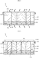
- FIG. 3 is a cross-sectioned view showing the battery module of FIG. 1
- FIG. 4 is a diagram for illustrating the coupling between a top plate and a cell housing of the battery module of FIG. 1
- FIG. 5 is a diagram for illustrating the connection of the electrode of the battery cells of the battery module of FIG. 1
- FIG. 6 is a diagram for illustrating a cooling principle of the battery module of FIG. 1 .
- a battery module 10 may include a battery cell 100, a cell housing 200, at least one cell fixing member 300, 400, a heatsink 500, a phase change material 600, a top plate 700 and a bottom plate 800.
- the battery cell 100 may be provided in plural, and the plurality of battery cells 100 may be cylindrical secondary batteries.
- the plurality of battery cells 100 may be stacked on one another and electrically connected to each other.
- a positive electrode 110 may be provided at a center of an upper portion of the plurality of battery cells 100, and a negative electrode 130 may be provided at an outer surface, including a rim, and a bottom surface of the plurality of battery cells 100.
- the cell housing 200 may be configured to accommodate the plurality of battery cells 100. To this end, the cell housing 200 may have an accommodation space for accommodating the plurality of battery cells 100 therein.
- a guide rib 220 may be provided inside the cell housing 200.
- the guide rib 200 is provided at an upper side of an inner wall of the cell housing 200 and may guide the movement of the phase change material 600 to a lower side during liquefaction (L) of the phase change material 600, explained later. Specifically, the guide rib 200 may guide faster movement of the liquefied (L) phase change material 600, explained later toward the bottom plate 800, explained later.
- the at least one cell fixing member 300, 400 may fix the plurality of battery cells 100 so as to prevent the plurality of battery cells 100 from moving within the cell housing 200.
- the cell fixing member 300, 400 may be provided in a pair.
- the pair of cell fixing members 300, 400 may include an upper cell fixing member 300 and a lower cell fixing member 400.
- An upper portion of the plurality of battery cells 100 is inserted into the upper cell fixing member 300, and the upper cell fixing member 300 may be fixed to an upper side of the inside of the cell housing 200.
- a plurality of cell insertion holes 350 may be formed in the upper cell fixing member 300 so that the upper portion of the plurality of battery cells 100 is inserted therein.
- a lower portion of the cell housing 200 is inserted into the lower cell fixing member 400, and the lower cell fixing member 400 may be fixed to a lower side of the inside of the cell housing 200.
- a plurality of cell insertion holes 450 may be formed in the lower cell fixing member 400 so that the lower portion of the plurality of battery cells 100 is inserted therein.
- the heatsink 500 is for cooling the plurality of battery cells 100 and may be mounted to an upper side of the top plate 700, explained later.
- the heatsink 500 may also be mounted to the cell housing 200, instead of the upper side of the top plate 700, explained later.
- the phase change material 600 is configured to guide the cooling of the plurality of battery cells 100 and may be partially filled in the cell housing 200. Accordingly, the plurality of battery cells 100 may be partially submerged in the phase change material 600 inside the cell housing 200.
- the phase change material 600 may be vaporized (V) and move toward the top plate 700, explained later, when a temperature of the plurality of battery cells 100 is raised, and be liquefied (L) by the heatsink 500 and move toward the bottom plate 800, explained later.
- the vaporization (V) and the liquefaction (L) may be repeated cyclically, through which the battery cells 100 may be cooled more effectively.
- the phase change material 600 may be a fluorine-based material with a low boiling point for more effective circulation.
- the phase change material 600 may be a material having a boiling point between 35°C and 50°C.
- the phase change material 600 may include a material having a fire extinguishing function. Accordingly, when a fire occurs in the battery module 10, the fire may be rapidly suppressed using the phase change material 600.
- the top plate 700 may be coupled to the cell housing 200 to cover the entire upper side of the cell housing 200.
- the top plate 700 may be coupled to the cell housing 200 through a seaming structure. This is to maximize the airtight structure of the cell housing 200 and to prevent the phase change material 600 in the cell housing 200 from being vaporized.
- the seaming structure may be made in a rim of the top plate 700 and in an upper rim of the cell housing 200. That is, the rim of the top plate 700 may be bonded to the upper rim of the cell housing 200 by seaming.
- the top plate 700 may be electrically connected to one of the positive electrodes 110 and the negative electrodes 130 of the plurality of battery cells 100.
- this embodiment will be described based on the case where the top plate 700 is electrically connected to the positive electrodes 110 of the plurality of battery cells 100.
- the top plate 700 may be made of a metal material and coupled to the positive electrodes 110 of the plurality of battery cells 100 by welding. That is, in this embodiment, the top plate 700 serves not only as a cover for sealing the cell housing 200 but also as a bus bar for the electrical connection of the battery cells 100.
- the top plate 700 may implement both functions as above, a separate bus bar structure for connecting the positive electrodes 110 of the battery cells 100 is not required.
- the top plate 700 may be insulated at a portion coupled to the cell housing 200.
- the top plate 700 may be insulated from the cell housing 200 at the rim portion that is bonded by seaming. If the cell housing 200 is not made of a metal material but made of a non-metallic material, the insulation treatment may be omitted.
- the bottom plate 800 may be disposed to face the top plate 700 and cover an entire lower side of the cell housing 200.
- the bottom plate 800 may be integrally formed with the cell housing 200 or may be separately provided and mounted to the bottom of the cell housing 200.
- the bottom plate 800 may be electrically connected to the other of the positive electrodes 110 and the negative electrodes 130 of the plurality of battery cells 100.
- the bottom plate 800 since the top plate 700 is electrically connected to the positive electrodes 110 of the plurality of battery cells 100, the bottom plate 800 will be described as being electrically connected to the negative electrodes 130 of the plurality of battery cells 100.
- the bottom plate 800 may serve not only as a cover for sealing the bottom of the cell housing 200 but also as a bus bar for the electrical connection of the battery cells 100 along with the top plate 700.
- the bottom plate 800 may be made of a metal material and coupled to the negative electrodes 130 of the plurality of battery cells 100 by welding. Meanwhile, if the bottom plate 800 is integrally formed with the cell housing 200, the cell housing 200 may also be made of a metal material. In this case, the cell housing 200 may be insulated at a portion coupled to the top plate 700 as described above for insulation with the top plate 700. If the bottom plate 800 is separately mounted to the cell housing 200, the cell housing 200 may be made of a non-metallic material, and in this case, the insulation process may be omitted.
- the bottom plate 800 enables the sealing of the cell housing 200 and the electrical connection of the negative electrodes 130 of the battery cells 100, a separate bus bar structure for connecting the negative electrodes 130 of the battery cells 100 is not required.
- top plate 700 and the bottom plate 800 for sealing the cell housing 200 also serve as bus bars for electrically connecting the electrodes 110, 130 of the battery cells 100, a separate additional bus bar structure may be omitted, thereby reducing the manufacturing cost of the battery module 10 and improving manufacturing efficiency.
- the battery module 10 may ensure a further capacity of the battery cells 100 as much as the volume of the separate additional bus bar structure that is omitted.
- the battery module 10 may maximize the cooling performance by means of the phase change material 600.
- FIG. 7 is a diagram for illustrating a battery pack according to an embodiment of the present disclosure.
- a battery pack 1 may include at least one battery module 10 according to the former embodiment and a pack case 50 for packaging the at least one battery module 10.
- the battery pack 1 may be provided to a vehicle as a fuel source of the vehicle.
- the battery pack 1 may be provided to an electric vehicle, a hybrid vehicle, and various other-type vehicles capable of using the battery pack 1 as a fuel source.
- the battery pack 1 may be provided in other devices, instruments or facilities such as an energy storage system using a secondary battery, in addition to the vehicle.
- the battery pack 1 of this embodiment and devices, instruments or facilities such as a vehicle, which have the battery pack 1 include the battery module 10 as described above, and thus it is possible to implement a battery pack 1 having all the advantages of the battery module 10 described above, or devices, instruments, facilities or the like such as a vehicle, which have the battery pack 1.
Landscapes
- Engineering & Computer Science (AREA)
- Chemical & Material Sciences (AREA)
- General Chemical & Material Sciences (AREA)
- Electrochemistry (AREA)
- Chemical Kinetics & Catalysis (AREA)
- Manufacturing & Machinery (AREA)
- Mechanical Engineering (AREA)
- Aviation & Aerospace Engineering (AREA)
- Transportation (AREA)
- Power Engineering (AREA)
- Sustainable Energy (AREA)
- Sustainable Development (AREA)
- Life Sciences & Earth Sciences (AREA)
- Secondary Cells (AREA)
- Battery Mounting, Suspending (AREA)
- Connection Of Batteries Or Terminals (AREA)
Abstract
Description
- The present disclosure relates to a battery module, a battery pack including the battery module, and a vehicle including the battery pack.
- The present application claims priority to Korean Patent Application No.
10-2017-0035398 filed on March 21, 2017 - Secondary batteries which are highly applicable to various products and exhibit superior electrical properties such as high energy density, etc. are commonly used not only in portable devices but also in electric vehicles (EVs) or hybrid electric vehicles (HEVs) driven by electrical power sources. The secondary battery is drawing attentions as a new energy source for enhancing environment friendliness and energy efficiency in that the use of fossil fuels can be reduced greatly and no byproduct is generated during energy consumption.
- Secondary batteries widely used at the preset include lithium ion batteries, lithium polymer batteries, nickel cadmium batteries, nickel hydrogen batteries, nickel zinc batteries and the like. An operating voltage of the unit secondary battery cell, namely a unit battery cell, is about 2.5V to 4.6V. Therefore, if a higher output voltage is required, a plurality of battery cells may be connected in series to configure a battery pack. In addition, depending on the charge/discharge capacity required for the battery pack, a plurality of battery cells may be connected in parallel to configure a battery pack. Thus, the number of battery cells included in the battery pack may be variously set according to the required output voltage or the demanded charge/discharge capacity.
- Meanwhile, when a plurality of battery cells are connected in series or in parallel to configure a battery pack, it is common to configure a battery module composed of at least one battery cell first, and then configure a battery pack by using at least one battery module and adding other components.
- Since the battery pack of a multi-module structure is manufactured such that aplurality of secondary batteries are densely packed in a narrow space, it is important to easily release the heat generated from each secondary battery. Since secondary batteries are charged and discharged by electrochemical reaction, if the heat of the battery module generated during charging and discharging is not effectively removed, heat accumulation occurs, which may promote deterioration of the battery module and, on occasions, cause ignition or explosion.
- Thus, a high-output large-capacity battery module and a battery pack equipped with it must have a cooling device for cooling the battery cells included therein.
- A conventional battery module typically employs a cooling structure that contacts a thermal interface material (TIM) between the battery cells and a heatsink to release the heat.
- However, in the conventional cooling structure, it is difficult to improve the performance of a battery module and a battery pack, and further the performance of an electric vehicle having the battery module or the battery pack due to low cooling performance.
- The present disclosure is directed to providing a battery module capable of maximizing the cooling performance, a battery pack including the battery module, and a vehicle including the battery pack.
- In one aspect of the present disclosure, there is provided a battery module, comprising: a plurality of battery cells stacked on one another; a cell housing configured to accommodate the plurality of battery cells; a top plate configured to cover an entire upper side of the cell housing and electrically connected to one of positive electrodes and negative electrodes of the plurality of battery cells; and a bottom plate disposed to face the top plate and configured to cover an entire lower side of the cell housing and electrically connected to the other of the positive electrodes and the negative electrodes of the plurality of battery cells.
- The battery module may further comprise a phase change material filled in the cell housing so that the plurality of battery cells are partially submerged therein and configured to guide cooling of the plurality of battery cells.
- The battery module may further comprise a heatsink mounted to an upper side of the top plate to cool the plurality of cells.
- The phase change material may be vaporized and move toward the top plate when a temperature of the plurality of battery cells is raised, and be liquefied by the heatsink and move toward the bottom plate.
- A guide rib may be provided at an upper side of an inner wall of the cell housing to guide movement of the liquefied phase change material toward the bottom plate.
- The battery module may further comprise at least one cell fixing member configured to fix the plurality of battery cells so as to prevent the plurality of battery cells from moving inside the cell housing.
- The cell fixing member may be provided in a pair, and the pair of cell fixing members may include: an upper cell fixing member into which an upper portion of the plurality of battery cells is inserted, the upper cell fixing member being fixed to an upper side of the inside of the cell housing; and a lower cell fixing member into which a lower portion of the plurality of battery cells is inserted, the lower cell fixing member being fixed to a lower side of the inside of the cell housing.
- A plurality of cell insert holes may be formed in the upper cell fixing member and the lower cell fixing member so that the plurality of battery cells are inserted therein.
- A rim of the top plate may be coupled to a rim of the cell housing by seaming.
- The top plate may be coupled to one electrodes of the plurality of battery cells by welding.
- The bottom plate may be coupled to the other electrodes of the plurality of battery cells by welding.
- The plurality of battery cells may be cylindrical secondary batteries.
- In another aspect of the present disclosure, there is also provided a battery pack, comprising: at least one battery module according to the above embodiments; and a pack case configured to package the at least one battery module.
- In another aspect of the present disclosure, there is also provided a vehicle, comprising at least one battery pack according to the above embodiments.
- According to various embodiments as above, it is possible to provide a battery module capable of maximizing the cooling performance, a battery pack including the battery module, and a vehicle including the battery pack.
- The accompanying drawings illustrate a preferred embodiment of the present disclosure and together with the foregoing disclosure, serve to provide further understanding of the technical features of the present disclosure, and thus, the present disclosure is not construed as being limited to the drawing.
-
FIG. 1 is a diagram for illustrating a battery module according to an embodiment of the present disclosure. -
FIG. 2 is an exploded perspective view showing the battery module ofFIG. 1 . -
FIG. 3 is a cross-sectioned view showing the battery module ofFIG. 1 . -
FIG. 4 is a diagram for illustrating the coupling between a top plate and a cell housing of the battery module ofFIG. 1 . -
FIG. 5 is a diagram for illustrating the connection of the electrode of the battery cells of the battery module ofFIG. 1 . -
FIG. 6 is a diagram for illustrating a cooling principle of the battery module ofFIG. 1 . -
FIG. 7 is a diagram for illustrating a battery pack according to an embodiment of the present disclosure. - The present disclosure will become more apparent by describing in detail the embodiments of the present disclosure with reference to the accompanying drawings. It should be understood that the embodiments disclosed herein are illustrative only for better understanding of the present disclosure, and that the present disclosure may be modified in various ways. In addition, for ease understanding of the present disclosure, the accompanying drawings are not drawn to real scale, but the dimensions of some components may be exaggerated.
-
FIG. 1 is a diagram for illustrating a battery module according to an embodiment of the present disclosure,FIG. 2 is an exploded perspective view showing the battery module ofFIG. 1 ,FIG. 3 is a cross-sectioned view showing the battery module ofFIG. 1 ,FIG. 4 is a diagram for illustrating the coupling between a top plate and a cell housing of the battery module ofFIG. 1 ,FIG. 5 is a diagram for illustrating the connection of the electrode of the battery cells of the battery module ofFIG. 1 , andFIG. 6 is a diagram for illustrating a cooling principle of the battery module ofFIG. 1 . - Referring to
FIGS. 1 to 6 , abattery module 10 may include abattery cell 100, acell housing 200, at least onecell fixing member heatsink 500, aphase change material 600, atop plate 700 and abottom plate 800. - The
battery cell 100 may be provided in plural, and the plurality ofbattery cells 100 may be cylindrical secondary batteries. The plurality ofbattery cells 100 may be stacked on one another and electrically connected to each other. - A
positive electrode 110 may be provided at a center of an upper portion of the plurality ofbattery cells 100, and anegative electrode 130 may be provided at an outer surface, including a rim, and a bottom surface of the plurality ofbattery cells 100. - The
cell housing 200 may be configured to accommodate the plurality ofbattery cells 100. To this end, thecell housing 200 may have an accommodation space for accommodating the plurality ofbattery cells 100 therein. - A
guide rib 220 may be provided inside thecell housing 200. - The
guide rib 200 is provided at an upper side of an inner wall of thecell housing 200 and may guide the movement of thephase change material 600 to a lower side during liquefaction (L) of thephase change material 600, explained later. Specifically, theguide rib 200 may guide faster movement of the liquefied (L)phase change material 600, explained later toward thebottom plate 800, explained later. - The at least one
cell fixing member battery cells 100 so as to prevent the plurality ofbattery cells 100 from moving within thecell housing 200. - The
cell fixing member cell fixing members cell fixing member 300 and a lowercell fixing member 400. - An upper portion of the plurality of
battery cells 100 is inserted into the uppercell fixing member 300, and the uppercell fixing member 300 may be fixed to an upper side of the inside of thecell housing 200. For this purpose, a plurality ofcell insertion holes 350 may be formed in the uppercell fixing member 300 so that the upper portion of the plurality ofbattery cells 100 is inserted therein. - A lower portion of the
cell housing 200 is inserted into the lowercell fixing member 400, and the lowercell fixing member 400 may be fixed to a lower side of the inside of thecell housing 200. For this purpose, a plurality ofcell insertion holes 450 may be formed in the lowercell fixing member 400 so that the lower portion of the plurality ofbattery cells 100 is inserted therein. - The
heatsink 500 is for cooling the plurality ofbattery cells 100 and may be mounted to an upper side of thetop plate 700, explained later. Theheatsink 500 may also be mounted to thecell housing 200, instead of the upper side of thetop plate 700, explained later. - The
phase change material 600 is configured to guide the cooling of the plurality ofbattery cells 100 and may be partially filled in thecell housing 200. Accordingly, the plurality ofbattery cells 100 may be partially submerged in thephase change material 600 inside thecell housing 200. - The
phase change material 600 may be vaporized (V) and move toward thetop plate 700, explained later, when a temperature of the plurality ofbattery cells 100 is raised, and be liquefied (L) by theheatsink 500 and move toward thebottom plate 800, explained later. The vaporization (V) and the liquefaction (L) may be repeated cyclically, through which thebattery cells 100 may be cooled more effectively. - The
phase change material 600 may be a fluorine-based material with a low boiling point for more effective circulation. For example, thephase change material 600 may be a material having a boiling point between 35°C and 50°C. Moreover, thephase change material 600 may include a material having a fire extinguishing function. Accordingly, when a fire occurs in thebattery module 10, the fire may be rapidly suppressed using thephase change material 600. - The
top plate 700 may be coupled to thecell housing 200 to cover the entire upper side of thecell housing 200. Here, thetop plate 700 may be coupled to thecell housing 200 through a seaming structure. This is to maximize the airtight structure of thecell housing 200 and to prevent thephase change material 600 in thecell housing 200 from being vaporized. The seaming structure may be made in a rim of thetop plate 700 and in an upper rim of thecell housing 200. That is, the rim of thetop plate 700 may be bonded to the upper rim of thecell housing 200 by seaming. - The
top plate 700 may be electrically connected to one of thepositive electrodes 110 and thenegative electrodes 130 of the plurality ofbattery cells 100. Hereinafter, this embodiment will be described based on the case where thetop plate 700 is electrically connected to thepositive electrodes 110 of the plurality ofbattery cells 100. - For this purpose, the
top plate 700 may be made of a metal material and coupled to thepositive electrodes 110 of the plurality ofbattery cells 100 by welding. That is, in this embodiment, thetop plate 700 serves not only as a cover for sealing thecell housing 200 but also as a bus bar for the electrical connection of thebattery cells 100. - Accordingly, in this embodiment, since the
top plate 700 may implement both functions as above, a separate bus bar structure for connecting thepositive electrodes 110 of thebattery cells 100 is not required. - Meanwhile, for insulation between the
top plate 700 and thecell housing 200, thetop plate 700 may be insulated at a portion coupled to thecell housing 200. In this embodiment, thetop plate 700 may be insulated from thecell housing 200 at the rim portion that is bonded by seaming. If thecell housing 200 is not made of a metal material but made of a non-metallic material, the insulation treatment may be omitted. - The
bottom plate 800 may be disposed to face thetop plate 700 and cover an entire lower side of thecell housing 200. Thebottom plate 800 may be integrally formed with thecell housing 200 or may be separately provided and mounted to the bottom of thecell housing 200. - The
bottom plate 800 may be electrically connected to the other of thepositive electrodes 110 and thenegative electrodes 130 of the plurality ofbattery cells 100. In this embodiment, since thetop plate 700 is electrically connected to thepositive electrodes 110 of the plurality ofbattery cells 100, thebottom plate 800 will be described as being electrically connected to thenegative electrodes 130 of the plurality ofbattery cells 100. - As described above, the
bottom plate 800 may serve not only as a cover for sealing the bottom of thecell housing 200 but also as a bus bar for the electrical connection of thebattery cells 100 along with thetop plate 700. - To this end, the
bottom plate 800 may be made of a metal material and coupled to thenegative electrodes 130 of the plurality ofbattery cells 100 by welding. Meanwhile, if thebottom plate 800 is integrally formed with thecell housing 200, thecell housing 200 may also be made of a metal material. In this case, thecell housing 200 may be insulated at a portion coupled to thetop plate 700 as described above for insulation with thetop plate 700. If thebottom plate 800 is separately mounted to thecell housing 200, thecell housing 200 may be made of a non-metallic material, and in this case, the insulation process may be omitted. - Accordingly, in this embodiment, since the
bottom plate 800 enables the sealing of thecell housing 200 and the electrical connection of thenegative electrodes 130 of thebattery cells 100, a separate bus bar structure for connecting thenegative electrodes 130 of thebattery cells 100 is not required. - As described above, in this embodiment, since the
top plate 700 and thebottom plate 800 for sealing thecell housing 200 also serve as bus bars for electrically connecting theelectrodes battery cells 100, a separate additional bus bar structure may be omitted, thereby reducing the manufacturing cost of thebattery module 10 and improving manufacturing efficiency. - In addition, in terms of energy density, the
battery module 10 according to this embodiment may ensure a further capacity of thebattery cells 100 as much as the volume of the separate additional bus bar structure that is omitted. - Moreover, the
battery module 10 according to this embodiment may maximize the cooling performance by means of thephase change material 600. -
FIG. 7 is a diagram for illustrating a battery pack according to an embodiment of the present disclosure. - Referring to
FIG. 7 , a battery pack 1 may include at least onebattery module 10 according to the former embodiment and apack case 50 for packaging the at least onebattery module 10. - The battery pack 1 may be provided to a vehicle as a fuel source of the vehicle. As an example, the battery pack 1 may be provided to an electric vehicle, a hybrid vehicle, and various other-type vehicles capable of using the battery pack 1 as a fuel source. In addition, the battery pack 1 may be provided in other devices, instruments or facilities such as an energy storage system using a secondary battery, in addition to the vehicle.
- As described above, the battery pack 1 of this embodiment and devices, instruments or facilities such as a vehicle, which have the battery pack 1, include the
battery module 10 as described above, and thus it is possible to implement a battery pack 1 having all the advantages of thebattery module 10 described above, or devices, instruments, facilities or the like such as a vehicle, which have the battery pack 1. - While the embodiments of the present disclosure have been shown and described, it should be understood that the present disclosure is not limited to the specific embodiments described, and that various changes and modifications can be made within the scope of the present disclosure by those skilled in the art, and these modifications should not be understood individually from the technical ideas and views of the present disclosure.
Claims (14)
- A battery module, comprising:a plurality of battery cells stacked on one another;a cell housing configured to accommodate the plurality of battery cells;a top plate configured to cover an entire upper side of the cell housing and electrically connected to one of positive electrodes and negative electrodes of the plurality of battery cells; anda bottom plate disposed to face the top plate and configured to cover an entire lower side of the cell housing and electrically connected to the other of the positive electrodes and the negative electrodes of the plurality of battery cells.
- The battery module according to claim 1, further comprising:
a phase change material filled in the cell housing so that the plurality of battery cells are partially submerged therein and configured to guide cooling of the plurality of battery cells. - The battery module according to claim 2, further comprising:
a heatsink mounted to an upper side of the top plate to cool the plurality of cells. - The battery module according to claim 3,
wherein the phase change material is vaporized and moves toward the top plate when a temperature of the plurality of battery cells is raised, and is liquefied by the heatsink and moves toward the bottom plate. - The battery module according to claim 4, further comprising:
a guide rib provided at an upper side of an inner wall of the cell housing to guide movement of the liquefied phase change material toward the bottom plate. - The battery module according to claim 1, further comprising:
at least one cell fixing member configured to fix the plurality of battery cells so as to prevent the plurality of battery cells from moving inside the cell housing. - The battery module according to claim 6,
wherein the cell fixing member is provided in a pair, and
wherein the pair of cell fixing members include:an upper cell fixing member into which an upper portion of the plurality of battery cells is inserted, the upper cell fixing member being fixed to an upper side of the inside of the cell housing; anda lower cell fixing member into which a lower portion of the plurality of battery cells is inserted, the lower cell fixing member being fixed to a lower side of the inside of the cell housing. - The battery module according to claim 7,
wherein a plurality of cell insert holes are formed in the upper cell fixing member and the lower cell fixing member so that the plurality of battery cells are inserted therein. - The battery module according to claim 1,
wherein a rim of the top plate is coupled to a rim of the cell housing by seaming. - The battery module according to claim 1,
wherein the top plate is coupled to one electrodes of the plurality of battery cells by welding. - The battery module according to claim 1,
wherein the bottom plate is coupled to the other electrodes of the plurality of battery cells by welding. - The battery module according to claim 1,
wherein the plurality of battery cells are cylindrical secondary batteries. - A battery pack, comprising:at least one battery module as defined in claim 1; anda pack case configured to package the at least one battery module.
- A vehicle, comprising:
at least one battery pack as defined in claim 13.
Priority Applications (1)
| Application Number | Priority Date | Filing Date | Title |
|---|---|---|---|
| PL18770713T PL3460871T3 (en) | 2017-03-21 | 2018-02-19 | Battery module, battery pack including the battery module, and automobile including the battery pack |
Applications Claiming Priority (2)
| Application Number | Priority Date | Filing Date | Title |
|---|---|---|---|
| KR1020170035398A KR102249504B1 (en) | 2017-03-21 | 2017-03-21 | Battery module, battery pack comprising the battery module and vehicle comprising the battery pack |
| PCT/KR2018/002007 WO2018174414A1 (en) | 2017-03-21 | 2018-02-19 | Battery module, battery pack including the battery module, and automobile including the battery pack |
Publications (3)
| Publication Number | Publication Date |
|---|---|
| EP3460871A1 true EP3460871A1 (en) | 2019-03-27 |
| EP3460871A4 EP3460871A4 (en) | 2019-10-23 |
| EP3460871B1 EP3460871B1 (en) | 2020-10-07 |
Family
ID=63586162
Family Applications (1)
| Application Number | Title | Priority Date | Filing Date |
|---|---|---|---|
| EP18770713.8A Active EP3460871B1 (en) | 2017-03-21 | 2018-02-19 | Battery module, battery pack including the battery module, and automobile including the battery pack |
Country Status (7)
| Country | Link |
|---|---|
| US (1) | US10854936B2 (en) |
| EP (1) | EP3460871B1 (en) |
| JP (1) | JP6762381B2 (en) |
| KR (1) | KR102249504B1 (en) |
| CN (1) | CN109417141B (en) |
| PL (1) | PL3460871T3 (en) |
| WO (1) | WO2018174414A1 (en) |
Cited By (1)
| Publication number | Priority date | Publication date | Assignee | Title |
|---|---|---|---|---|
| CN114041230A (en) * | 2019-08-07 | 2022-02-11 | 株式会社Lg新能源 | Top cooling type battery pack |
Families Citing this family (11)
| Publication number | Priority date | Publication date | Assignee | Title |
|---|---|---|---|---|
| KR102169631B1 (en) * | 2017-03-21 | 2020-10-23 | 주식회사 엘지화학 | Battery module, battery pack comprising the battery module and vehicle comprising the battery pack |
| US11094977B2 (en) * | 2019-08-30 | 2021-08-17 | Baidu Usa Llc | Battery thermal management system with passive battery pack cooling |
| US20220399605A1 (en) * | 2019-11-12 | 2022-12-15 | Saic Motor Corporation Limited | Battery energy storage module and battery energy storage device |
| KR102216862B1 (en) * | 2020-09-02 | 2021-02-17 | 구승조 | A Battery Module and Manufacturing Method of the same |
| US11967724B2 (en) * | 2020-10-06 | 2024-04-23 | Rivian Ip Holdings, Llc | Battery module support beam |
| KR20220048783A (en) * | 2020-10-13 | 2022-04-20 | 주식회사 엘지에너지솔루션 | Battery module, battery pack comprising the battery module and vehicle comprising the battery pack |
| KR20220066461A (en) * | 2020-11-16 | 2022-05-24 | 주식회사 엘지에너지솔루션 | Cell Module Having Guide Frame and Its Manufacturing Method |
| CN112687982B (en) * | 2020-12-28 | 2022-04-12 | 合肥国轩高科动力能源有限公司 | Battery cooling module |
| CN112537385B (en) * | 2020-12-30 | 2023-03-21 | 山东济燃氢动力有限公司 | Hydrogen fuel cell motorcycle |
| KR20240047580A (en) * | 2022-10-05 | 2024-04-12 | 주식회사 엘지에너지솔루션 | Welding-free battery module |
| WO2024194309A1 (en) * | 2023-03-21 | 2024-09-26 | Sabic Global Technologies B.V. | Battery pack with battery module partially submerged in coolant |
Family Cites Families (23)
| Publication number | Priority date | Publication date | Assignee | Title |
|---|---|---|---|---|
| JP3780396B2 (en) | 1996-12-30 | 2006-05-31 | 株式会社ジーエス・ユアサコーポレーション | Oil-immersed equal-pressure storage battery |
| US6468689B1 (en) | 2000-02-29 | 2002-10-22 | Illinois Institute Of Technology | Thermal management of battery systems |
| US6942944B2 (en) | 2000-02-29 | 2005-09-13 | Illinois Institute Of Technology | Battery system thermal management |
| CN100470916C (en) | 2005-11-08 | 2009-03-18 | 比亚迪股份有限公司 | Lithium ion secondary battery |
| JP2007165032A (en) | 2005-12-12 | 2007-06-28 | Toyota Motor Corp | Battery |
| JP5070697B2 (en) * | 2005-12-19 | 2012-11-14 | 日産自動車株式会社 | Battery module |
| JP2010211963A (en) | 2009-03-06 | 2010-09-24 | Toyota Motor Corp | Power storage apparatus |
| WO2011064956A1 (en) | 2009-11-25 | 2011-06-03 | パナソニック株式会社 | Battery module |
| CN201853773U (en) * | 2010-10-25 | 2011-06-01 | 天瑞企业股份有限公司 | Rechargeable battery assembling mechanism |
| US20130011710A1 (en) | 2011-01-07 | 2013-01-10 | Keisuke Naito | Battery pack |
| EP2590241B1 (en) | 2011-05-30 | 2015-08-26 | Panasonic Intellectual Property Management Co., Ltd. | Cell block and method for manufacturing same |
| KR101560556B1 (en) | 2012-08-10 | 2015-10-16 | 주식회사 엘지화학 | Battery Pack Containing Coolant of High Specific Heat, High Viscosity and Electric Insulation |
| CN106058100B (en) * | 2012-09-06 | 2018-11-13 | 阿提瓦公司 | Frame has the battery component of dispensing block |
| KR20140081949A (en) * | 2012-12-20 | 2014-07-02 | 포스코에너지 주식회사 | Battery module for sodium rechargable battery |
| US9912019B2 (en) * | 2013-05-20 | 2018-03-06 | Hamilton Sundstrand Corporation | Thermal management of electrical storage devices by coolant pool |
| EP2950379A1 (en) * | 2014-05-30 | 2015-12-02 | Siemens Aktiengesellschaft | Electrical energy storage device |
| KR101715698B1 (en) * | 2014-09-22 | 2017-03-13 | 주식회사 엘지화학 | Battery module comprising heat transfer device using wick for cooling part |
| JP6365186B2 (en) | 2014-09-29 | 2018-08-01 | 豊田合成株式会社 | Busbar module |
| CA2975062A1 (en) * | 2015-01-30 | 2016-08-04 | Consortium De Recherche Brp - Universite De Sherbrooke S.E.N.C. | Battery pack |
| KR101679963B1 (en) | 2015-04-14 | 2016-12-06 | 현대자동차주식회사 | Battery moudle |
| CN204760451U (en) * | 2015-06-17 | 2015-11-11 | 深圳市拓思创新科技有限公司 | Lithium cell packaging structure and lithium cell |
| KR101679982B1 (en) * | 2015-09-14 | 2016-11-25 | 현대자동차주식회사 | Battery device |
| CN106329027A (en) * | 2016-11-07 | 2017-01-11 | 天津力神特种电源科技股份公司 | High-safety lithium ion battery pack |
-
2017
- 2017-03-21 KR KR1020170035398A patent/KR102249504B1/en active IP Right Grant
-
2018
- 2018-02-19 CN CN201880002490.5A patent/CN109417141B/en active Active
- 2018-02-19 EP EP18770713.8A patent/EP3460871B1/en active Active
- 2018-02-19 US US16/307,789 patent/US10854936B2/en active Active
- 2018-02-19 WO PCT/KR2018/002007 patent/WO2018174414A1/en unknown
- 2018-02-19 JP JP2018565697A patent/JP6762381B2/en active Active
- 2018-02-19 PL PL18770713T patent/PL3460871T3/en unknown
Cited By (2)
| Publication number | Priority date | Publication date | Assignee | Title |
|---|---|---|---|---|
| CN114041230A (en) * | 2019-08-07 | 2022-02-11 | 株式会社Lg新能源 | Top cooling type battery pack |
| CN114041230B (en) * | 2019-08-07 | 2024-08-09 | 株式会社Lg新能源 | Top-cooled battery pack |
Also Published As
| Publication number | Publication date |
|---|---|
| KR102249504B1 (en) | 2021-05-06 |
| PL3460871T3 (en) | 2021-04-06 |
| EP3460871B1 (en) | 2020-10-07 |
| JP6762381B2 (en) | 2020-09-30 |
| WO2018174414A1 (en) | 2018-09-27 |
| CN109417141A (en) | 2019-03-01 |
| EP3460871A4 (en) | 2019-10-23 |
| US20190267684A1 (en) | 2019-08-29 |
| JP2019518313A (en) | 2019-06-27 |
| CN109417141B (en) | 2021-10-29 |
| US10854936B2 (en) | 2020-12-01 |
| KR20180106687A (en) | 2018-10-01 |
Similar Documents
| Publication | Publication Date | Title |
|---|---|---|
| EP3460871B1 (en) | Battery module, battery pack including the battery module, and automobile including the battery pack | |
| EP3474345B1 (en) | Battery module, battery pack including the battery module, and automobile including the battery pack | |
| US11699819B2 (en) | Battery cell assembly, battery module including same battery cell assembly, battery pack including same battery module, and automobile including same battery pack | |
| EP3780250B1 (en) | Battery module, battery pack comprising same battery module, and vehicle comprising same battery pack | |
| EP3282515B1 (en) | Battery module, battery pack comprising battery module, and vehicle comprising battery pack | |
| US11024896B2 (en) | Battery module with cooling unit to cover exposed parts of adjacent battery cell assemblies. Battery pack including battery module, and vehicle including battery pack | |
| EP3291360B1 (en) | Battery pack and vehicle including such battery pack | |
| EP3567669B1 (en) | Battery module, battery pack comprising battery module, and automobile comprising battery pack | |
| EP3361554A1 (en) | Battery module, battery pack comprising battery module, and vehicle comprising battery pack | |
| EP3675275A1 (en) | Battery module, battery pack including same battery module, and vehicle including same battery pack | |
| EP3522254B1 (en) | Battery module, battery pack including battery module, and vehicle including battery pack | |
| EP4012823A1 (en) | Battery module, and battery rack and power storage device, each comprising same battery module | |
| US20230327236A1 (en) | Battery module, battery pack comprising battery module, and vehicle comprising battery pack |
Legal Events
| Date | Code | Title | Description |
|---|---|---|---|
| STAA | Information on the status of an ep patent application or granted ep patent |
Free format text: STATUS: THE INTERNATIONAL PUBLICATION HAS BEEN MADE |
|
| PUAI | Public reference made under article 153(3) epc to a published international application that has entered the european phase |
Free format text: ORIGINAL CODE: 0009012 |
|
| STAA | Information on the status of an ep patent application or granted ep patent |
Free format text: STATUS: REQUEST FOR EXAMINATION WAS MADE |
|
| 17P | Request for examination filed |
Effective date: 20181218 |
|
| AK | Designated contracting states |
Kind code of ref document: A1 Designated state(s): AL AT BE BG CH CY CZ DE DK EE ES FI FR GB GR HR HU IE IS IT LI LT LU LV MC MK MT NL NO PL PT RO RS SE SI SK SM TR |
|
| AX | Request for extension of the european patent |
Extension state: BA ME |
|
| A4 | Supplementary search report drawn up and despatched |
Effective date: 20190925 |
|
| RIC1 | Information provided on ipc code assigned before grant |
Ipc: H01M 10/613 20140101ALI20190919BHEP Ipc: H01M 10/04 20060101ALI20190919BHEP Ipc: H01M 10/6554 20140101ALI20190919BHEP Ipc: H01M 2/20 20060101ALI20190919BHEP Ipc: H01M 10/6551 20140101ALI20190919BHEP Ipc: H01M 10/625 20140101ALI20190919BHEP Ipc: H01M 2/10 20060101AFI20190919BHEP Ipc: H01M 10/6569 20140101ALI20190919BHEP |
|
| GRAP | Despatch of communication of intention to grant a patent |
Free format text: ORIGINAL CODE: EPIDOSNIGR1 |
|
| STAA | Information on the status of an ep patent application or granted ep patent |
Free format text: STATUS: GRANT OF PATENT IS INTENDED |
|
| DAV | Request for validation of the european patent (deleted) | ||
| DAX | Request for extension of the european patent (deleted) | ||
| INTG | Intention to grant announced |
Effective date: 20200626 |
|
| GRAS | Grant fee paid |
Free format text: ORIGINAL CODE: EPIDOSNIGR3 |
|
| GRAA | (expected) grant |
Free format text: ORIGINAL CODE: 0009210 |
|
| STAA | Information on the status of an ep patent application or granted ep patent |
Free format text: STATUS: THE PATENT HAS BEEN GRANTED |
|
| AK | Designated contracting states |
Kind code of ref document: B1 Designated state(s): AL AT BE BG CH CY CZ DE DK EE ES FI FR GB GR HR HU IE IS IT LI LT LU LV MC MK MT NL NO PL PT RO RS SE SI SK SM TR |
|
| REG | Reference to a national code |
Ref country code: GB Ref legal event code: FG4D |
|
| REG | Reference to a national code |
Ref country code: AT Ref legal event code: REF Ref document number: 1322110 Country of ref document: AT Kind code of ref document: T Effective date: 20201015 Ref country code: CH Ref legal event code: EP |
|
| REG | Reference to a national code |
Ref country code: IE Ref legal event code: FG4D |
|
| REG | Reference to a national code |
Ref country code: DE Ref legal event code: R096 Ref document number: 602018008564 Country of ref document: DE |
|
| REG | Reference to a national code |
Ref country code: DE Ref legal event code: R079 Ref document number: 602018008564 Country of ref document: DE Free format text: PREVIOUS MAIN CLASS: H01M0002100000 Ipc: H01M0050200000 |
|
| REG | Reference to a national code |
Ref country code: SE Ref legal event code: TRGR |
|
| REG | Reference to a national code |
Ref country code: NL Ref legal event code: MP Effective date: 20201007 |
|
| REG | Reference to a national code |
Ref country code: AT Ref legal event code: MK05 Ref document number: 1322110 Country of ref document: AT Kind code of ref document: T Effective date: 20201007 |
|
| PG25 | Lapsed in a contracting state [announced via postgrant information from national office to epo] |
Ref country code: GR Free format text: LAPSE BECAUSE OF FAILURE TO SUBMIT A TRANSLATION OF THE DESCRIPTION OR TO PAY THE FEE WITHIN THE PRESCRIBED TIME-LIMIT Effective date: 20210108 Ref country code: NO Free format text: LAPSE BECAUSE OF FAILURE TO SUBMIT A TRANSLATION OF THE DESCRIPTION OR TO PAY THE FEE WITHIN THE PRESCRIBED TIME-LIMIT Effective date: 20210107 Ref country code: PT Free format text: LAPSE BECAUSE OF FAILURE TO SUBMIT A TRANSLATION OF THE DESCRIPTION OR TO PAY THE FEE WITHIN THE PRESCRIBED TIME-LIMIT Effective date: 20210208 Ref country code: RS Free format text: LAPSE BECAUSE OF FAILURE TO SUBMIT A TRANSLATION OF THE DESCRIPTION OR TO PAY THE FEE WITHIN THE PRESCRIBED TIME-LIMIT Effective date: 20201007 Ref country code: FI Free format text: LAPSE BECAUSE OF FAILURE TO SUBMIT A TRANSLATION OF THE DESCRIPTION OR TO PAY THE FEE WITHIN THE PRESCRIBED TIME-LIMIT Effective date: 20201007 |
|
| REG | Reference to a national code |
Ref country code: LT Ref legal event code: MG4D |
|
| PG25 | Lapsed in a contracting state [announced via postgrant information from national office to epo] |
Ref country code: ES Free format text: LAPSE BECAUSE OF FAILURE TO SUBMIT A TRANSLATION OF THE DESCRIPTION OR TO PAY THE FEE WITHIN THE PRESCRIBED TIME-LIMIT Effective date: 20201007 Ref country code: AT Free format text: LAPSE BECAUSE OF FAILURE TO SUBMIT A TRANSLATION OF THE DESCRIPTION OR TO PAY THE FEE WITHIN THE PRESCRIBED TIME-LIMIT Effective date: 20201007 Ref country code: IS Free format text: LAPSE BECAUSE OF FAILURE TO SUBMIT A TRANSLATION OF THE DESCRIPTION OR TO PAY THE FEE WITHIN THE PRESCRIBED TIME-LIMIT Effective date: 20210207 Ref country code: LV Free format text: LAPSE BECAUSE OF FAILURE TO SUBMIT A TRANSLATION OF THE DESCRIPTION OR TO PAY THE FEE WITHIN THE PRESCRIBED TIME-LIMIT Effective date: 20201007 Ref country code: BG Free format text: LAPSE BECAUSE OF FAILURE TO SUBMIT A TRANSLATION OF THE DESCRIPTION OR TO PAY THE FEE WITHIN THE PRESCRIBED TIME-LIMIT Effective date: 20210107 |
|
| PG25 | Lapsed in a contracting state [announced via postgrant information from national office to epo] |
Ref country code: NL Free format text: LAPSE BECAUSE OF FAILURE TO SUBMIT A TRANSLATION OF THE DESCRIPTION OR TO PAY THE FEE WITHIN THE PRESCRIBED TIME-LIMIT Effective date: 20201007 Ref country code: HR Free format text: LAPSE BECAUSE OF FAILURE TO SUBMIT A TRANSLATION OF THE DESCRIPTION OR TO PAY THE FEE WITHIN THE PRESCRIBED TIME-LIMIT Effective date: 20201007 |
|
| REG | Reference to a national code |
Ref country code: DE Ref legal event code: R097 Ref document number: 602018008564 Country of ref document: DE |
|
| PG25 | Lapsed in a contracting state [announced via postgrant information from national office to epo] |
Ref country code: LT Free format text: LAPSE BECAUSE OF FAILURE TO SUBMIT A TRANSLATION OF THE DESCRIPTION OR TO PAY THE FEE WITHIN THE PRESCRIBED TIME-LIMIT Effective date: 20201007 Ref country code: RO Free format text: LAPSE BECAUSE OF FAILURE TO SUBMIT A TRANSLATION OF THE DESCRIPTION OR TO PAY THE FEE WITHIN THE PRESCRIBED TIME-LIMIT Effective date: 20201007 Ref country code: SK Free format text: LAPSE BECAUSE OF FAILURE TO SUBMIT A TRANSLATION OF THE DESCRIPTION OR TO PAY THE FEE WITHIN THE PRESCRIBED TIME-LIMIT Effective date: 20201007 Ref country code: SM Free format text: LAPSE BECAUSE OF FAILURE TO SUBMIT A TRANSLATION OF THE DESCRIPTION OR TO PAY THE FEE WITHIN THE PRESCRIBED TIME-LIMIT Effective date: 20201007 Ref country code: CZ Free format text: LAPSE BECAUSE OF FAILURE TO SUBMIT A TRANSLATION OF THE DESCRIPTION OR TO PAY THE FEE WITHIN THE PRESCRIBED TIME-LIMIT Effective date: 20201007 Ref country code: EE Free format text: LAPSE BECAUSE OF FAILURE TO SUBMIT A TRANSLATION OF THE DESCRIPTION OR TO PAY THE FEE WITHIN THE PRESCRIBED TIME-LIMIT Effective date: 20201007 |
|
| PLBE | No opposition filed within time limit |
Free format text: ORIGINAL CODE: 0009261 |
|
| STAA | Information on the status of an ep patent application or granted ep patent |
Free format text: STATUS: NO OPPOSITION FILED WITHIN TIME LIMIT |
|
| PG25 | Lapsed in a contracting state [announced via postgrant information from national office to epo] |
Ref country code: DK Free format text: LAPSE BECAUSE OF FAILURE TO SUBMIT A TRANSLATION OF THE DESCRIPTION OR TO PAY THE FEE WITHIN THE PRESCRIBED TIME-LIMIT Effective date: 20201007 |
|
| 26N | No opposition filed |
Effective date: 20210708 |
|
| PG25 | Lapsed in a contracting state [announced via postgrant information from national office to epo] |
Ref country code: MC Free format text: LAPSE BECAUSE OF FAILURE TO SUBMIT A TRANSLATION OF THE DESCRIPTION OR TO PAY THE FEE WITHIN THE PRESCRIBED TIME-LIMIT Effective date: 20201007 |
|
| REG | Reference to a national code |
Ref country code: BE Ref legal event code: MM Effective date: 20210228 |
|
| PG25 | Lapsed in a contracting state [announced via postgrant information from national office to epo] |
Ref country code: AL Free format text: LAPSE BECAUSE OF FAILURE TO SUBMIT A TRANSLATION OF THE DESCRIPTION OR TO PAY THE FEE WITHIN THE PRESCRIBED TIME-LIMIT Effective date: 20201007 Ref country code: CH Free format text: LAPSE BECAUSE OF NON-PAYMENT OF DUE FEES Effective date: 20210228 Ref country code: IT Free format text: LAPSE BECAUSE OF FAILURE TO SUBMIT A TRANSLATION OF THE DESCRIPTION OR TO PAY THE FEE WITHIN THE PRESCRIBED TIME-LIMIT Effective date: 20201007 Ref country code: LI Free format text: LAPSE BECAUSE OF NON-PAYMENT OF DUE FEES Effective date: 20210228 Ref country code: LU Free format text: LAPSE BECAUSE OF NON-PAYMENT OF DUE FEES Effective date: 20210219 |
|
| PG25 | Lapsed in a contracting state [announced via postgrant information from national office to epo] |
Ref country code: SI Free format text: LAPSE BECAUSE OF FAILURE TO SUBMIT A TRANSLATION OF THE DESCRIPTION OR TO PAY THE FEE WITHIN THE PRESCRIBED TIME-LIMIT Effective date: 20201007 |
|
| PG25 | Lapsed in a contracting state [announced via postgrant information from national office to epo] |
Ref country code: IE Free format text: LAPSE BECAUSE OF NON-PAYMENT OF DUE FEES Effective date: 20210219 |
|
| PG25 | Lapsed in a contracting state [announced via postgrant information from national office to epo] |
Ref country code: IS Free format text: LAPSE BECAUSE OF FAILURE TO SUBMIT A TRANSLATION OF THE DESCRIPTION OR TO PAY THE FEE WITHIN THE PRESCRIBED TIME-LIMIT Effective date: 20210207 |
|
| PG25 | Lapsed in a contracting state [announced via postgrant information from national office to epo] |
Ref country code: BE Free format text: LAPSE BECAUSE OF NON-PAYMENT OF DUE FEES Effective date: 20210228 |
|
| P01 | Opt-out of the competence of the unified patent court (upc) registered |
Effective date: 20230512 |
|
| PG25 | Lapsed in a contracting state [announced via postgrant information from national office to epo] |
Ref country code: CY Free format text: LAPSE BECAUSE OF FAILURE TO SUBMIT A TRANSLATION OF THE DESCRIPTION OR TO PAY THE FEE WITHIN THE PRESCRIBED TIME-LIMIT Effective date: 20201007 |
|
| PG25 | Lapsed in a contracting state [announced via postgrant information from national office to epo] |
Ref country code: HU Free format text: LAPSE BECAUSE OF FAILURE TO SUBMIT A TRANSLATION OF THE DESCRIPTION OR TO PAY THE FEE WITHIN THE PRESCRIBED TIME-LIMIT; INVALID AB INITIO Effective date: 20180219 |
|
| REG | Reference to a national code |
Ref country code: GB Ref legal event code: 732E Free format text: REGISTERED BETWEEN 20231026 AND 20231101 |
|
| REG | Reference to a national code |
Ref country code: DE Ref legal event code: R081 Ref document number: 602018008564 Country of ref document: DE Owner name: LG ENERGY SOLUTION, LTD., KR Free format text: FORMER OWNER: LG CHEM, LTD., SEOUL, KR |
|
| PG25 | Lapsed in a contracting state [announced via postgrant information from national office to epo] |
Ref country code: MK Free format text: LAPSE BECAUSE OF FAILURE TO SUBMIT A TRANSLATION OF THE DESCRIPTION OR TO PAY THE FEE WITHIN THE PRESCRIBED TIME-LIMIT Effective date: 20201007 |
|
| PGFP | Annual fee paid to national office [announced via postgrant information from national office to epo] |
Ref country code: DE Payment date: 20240122 Year of fee payment: 7 Ref country code: GB Payment date: 20240122 Year of fee payment: 7 |
|
| PGFP | Annual fee paid to national office [announced via postgrant information from national office to epo] |
Ref country code: SE Payment date: 20240123 Year of fee payment: 7 Ref country code: PL Payment date: 20240123 Year of fee payment: 7 Ref country code: FR Payment date: 20240123 Year of fee payment: 7 |
|
| PG25 | Lapsed in a contracting state [announced via postgrant information from national office to epo] |
Ref country code: TR Free format text: LAPSE BECAUSE OF FAILURE TO SUBMIT A TRANSLATION OF THE DESCRIPTION OR TO PAY THE FEE WITHIN THE PRESCRIBED TIME-LIMIT Effective date: 20201007 |
|
| PG25 | Lapsed in a contracting state [announced via postgrant information from national office to epo] |
Ref country code: MT Free format text: LAPSE BECAUSE OF FAILURE TO SUBMIT A TRANSLATION OF THE DESCRIPTION OR TO PAY THE FEE WITHIN THE PRESCRIBED TIME-LIMIT Effective date: 20201007 |