EP3689690A1 - Mit pneumatischem druck arbeitende bremsanlage für einen anhänger, landwirtschaftlicher lastenanhänger sowie zugverbund, umfassend eine landwirtschaftliche zugmaschine und einen damit gekoppelten landwirtschaftlichen lastenanhänger - Google Patents
Mit pneumatischem druck arbeitende bremsanlage für einen anhänger, landwirtschaftlicher lastenanhänger sowie zugverbund, umfassend eine landwirtschaftliche zugmaschine und einen damit gekoppelten landwirtschaftlichen lastenanhänger Download PDFInfo
- Publication number
- EP3689690A1 EP3689690A1 EP20150703.5A EP20150703A EP3689690A1 EP 3689690 A1 EP3689690 A1 EP 3689690A1 EP 20150703 A EP20150703 A EP 20150703A EP 3689690 A1 EP3689690 A1 EP 3689690A1
- Authority
- EP
- European Patent Office
- Prior art keywords
- trailer
- brake
- pressure
- agricultural
- brake system
- Prior art date
- Legal status (The legal status is an assumption and is not a legal conclusion. Google has not performed a legal analysis and makes no representation as to the accuracy of the status listed.)
- Granted
Links
Images
Classifications
-
- B—PERFORMING OPERATIONS; TRANSPORTING
- B60—VEHICLES IN GENERAL
- B60T—VEHICLE BRAKE CONTROL SYSTEMS OR PARTS THEREOF; BRAKE CONTROL SYSTEMS OR PARTS THEREOF, IN GENERAL; ARRANGEMENT OF BRAKING ELEMENTS ON VEHICLES IN GENERAL; PORTABLE DEVICES FOR PREVENTING UNWANTED MOVEMENT OF VEHICLES; VEHICLE MODIFICATIONS TO FACILITATE COOLING OF BRAKES
- B60T13/00—Transmitting braking action from initiating means to ultimate brake actuator with power assistance or drive; Brake systems incorporating such transmitting means, e.g. air-pressure brake systems
- B60T13/10—Transmitting braking action from initiating means to ultimate brake actuator with power assistance or drive; Brake systems incorporating such transmitting means, e.g. air-pressure brake systems with fluid assistance, drive, or release
- B60T13/24—Transmitting braking action from initiating means to ultimate brake actuator with power assistance or drive; Brake systems incorporating such transmitting means, e.g. air-pressure brake systems with fluid assistance, drive, or release the fluid being gaseous
- B60T13/26—Compressed-air systems
- B60T13/261—Compressed-air systems systems with both indirect application and application by springs or weights and released by compressed air
- B60T13/265—Compressed-air systems systems with both indirect application and application by springs or weights and released by compressed air dependent systems, e.g. trailer systems
-
- B—PERFORMING OPERATIONS; TRANSPORTING
- B60—VEHICLES IN GENERAL
- B60T—VEHICLE BRAKE CONTROL SYSTEMS OR PARTS THEREOF; BRAKE CONTROL SYSTEMS OR PARTS THEREOF, IN GENERAL; ARRANGEMENT OF BRAKING ELEMENTS ON VEHICLES IN GENERAL; PORTABLE DEVICES FOR PREVENTING UNWANTED MOVEMENT OF VEHICLES; VEHICLE MODIFICATIONS TO FACILITATE COOLING OF BRAKES
- B60T13/00—Transmitting braking action from initiating means to ultimate brake actuator with power assistance or drive; Brake systems incorporating such transmitting means, e.g. air-pressure brake systems
- B60T13/10—Transmitting braking action from initiating means to ultimate brake actuator with power assistance or drive; Brake systems incorporating such transmitting means, e.g. air-pressure brake systems with fluid assistance, drive, or release
- B60T13/66—Electrical control in fluid-pressure brake systems
- B60T13/68—Electrical control in fluid-pressure brake systems by electrically-controlled valves
- B60T13/683—Electrical control in fluid-pressure brake systems by electrically-controlled valves in pneumatic systems or parts thereof
-
- B—PERFORMING OPERATIONS; TRANSPORTING
- B60—VEHICLES IN GENERAL
- B60T—VEHICLE BRAKE CONTROL SYSTEMS OR PARTS THEREOF; BRAKE CONTROL SYSTEMS OR PARTS THEREOF, IN GENERAL; ARRANGEMENT OF BRAKING ELEMENTS ON VEHICLES IN GENERAL; PORTABLE DEVICES FOR PREVENTING UNWANTED MOVEMENT OF VEHICLES; VEHICLE MODIFICATIONS TO FACILITATE COOLING OF BRAKES
- B60T7/00—Brake-action initiating means
- B60T7/12—Brake-action initiating means for automatic initiation; for initiation not subject to will of driver or passenger
- B60T7/20—Brake-action initiating means for automatic initiation; for initiation not subject to will of driver or passenger specially for trailers, e.g. in case of uncoupling of or overrunning by trailer
-
- B—PERFORMING OPERATIONS; TRANSPORTING
- B60—VEHICLES IN GENERAL
- B60T—VEHICLE BRAKE CONTROL SYSTEMS OR PARTS THEREOF; BRAKE CONTROL SYSTEMS OR PARTS THEREOF, IN GENERAL; ARRANGEMENT OF BRAKING ELEMENTS ON VEHICLES IN GENERAL; PORTABLE DEVICES FOR PREVENTING UNWANTED MOVEMENT OF VEHICLES; VEHICLE MODIFICATIONS TO FACILITATE COOLING OF BRAKES
- B60T8/00—Arrangements for adjusting wheel-braking force to meet varying vehicular or ground-surface conditions, e.g. limiting or varying distribution of braking force
- B60T8/18—Arrangements for adjusting wheel-braking force to meet varying vehicular or ground-surface conditions, e.g. limiting or varying distribution of braking force responsive to vehicle weight or load, e.g. load distribution
- B60T8/1887—Arrangements for adjusting wheel-braking force to meet varying vehicular or ground-surface conditions, e.g. limiting or varying distribution of braking force responsive to vehicle weight or load, e.g. load distribution especially adapted for tractor-trailer combinations
Definitions
- the present invention relates to a pneumatic, hydraulic or similar brake system, a trailer equipped therewith and an agricultural train combination comprising a tractor and at least one trailer coupled thereto with a pneumatic, hydraulic or similar brake system.
- transport journeys In connection with agricultural logistics tasks, the most varied transport journeys have to be mastered, which naturally have to take place on public roads in many cases. Such transport journeys can be both transfer journeys for self-propelled machines or work machines attached to an agricultural tractor. However, many of these transport journeys are load transports, in which, for example, crops are transported from the field to the intended storage areas or for further processing after harvesting, or in which seeds or seedlings to be spread, fertilizer to be distributed or crop protection agents to be spread are carried in tanks or storage containers and brought to their destination shall be.
- Typical agricultural trailers can be transport trailers such as loading wagons, slurry transport and distribution trailers, trailed commercial fertilizer spreaders or the like, or also work trailers such as large trailed plows, dismantled cutting units of combine harvesters or forage harvesters, trailed seeders or numerous other agricultural working machines.
- Pneumatic brake systems with brake force adjusters for varying the brake pressure depending on the load are common in commercial vehicle construction. Brake force actuators of this type are also used in agricultural transport. However, the technical condition for this is that there is a possibility on the vehicle that allows a technical determination of the loading level. This is usually done by tapping the compression of the vehicle suspension or the like. The use of a suspension is, however, for certain types of work machines such technically not possible or sensible for seed drills. In addition, no other option can be used to tap the load status, as this would e.g. the tightness of containers can be negatively influenced by sprayers.
- such a brake force actuator works like a pressure relief valve, ie it cuts off the input pressure at a certain value so that the wheels of the lightly loaded or empty trailer do not tend to overbraking.
- the brake force actuator can fulfill its purpose, since the trailer brake valve controls the braking intensity and the maximum value of the brake force actuator, which can be changed manually If necessary, the maximum brake pressure is limited in order to prevent the undesired over-braking of the trailer wheels which is detrimental to driving stability.
- braking value ranges which are to be achieved at different braking intensities, are also referred to as brake bands to be observed. More precisely, a brake band denotes a specification of the bandwidth for the pressure increase in the brake system as a function of the deceleration.
- EBS braking system an electronic system for preventing wheels from locking when braking harder, a so-called EBS braking system, could unwanted blocking of the trailer wheels can be prevented, which would achieve the desired level of driving safety under largely all operating conditions that occur in practice.
- the present invention has set itself the task of being comparatively simple and therefore also inexpensive to provide a feasible system for pneumatic trailer brakes or a pneumatically operating trailer brake system that only requires fewer additional components than known pneumatic brake systems, so that it can be easily retrofitted to existing pneumatically operating brake systems with little assembly effort.
- the present invention proposes a brake system for a trailer working with pneumatic pressure with the features of the independent claim, wherein this brake system can be provided in particular for a trailer which can be used in agriculture.
- an automatically load-dependent brake force regulator for the brake force-dependent specification of an actuation force of at least two wheels associated with brake cylinders associated with a trailer axle.
- an input manipulated variable for load-dependent variation and / or throttling a control pressure of the brake cylinders can be specified manually, in particular depending on a load state of the trailer. Since the trailer in which the brake system is used usually does not have any suspension, there is no conventional input variable for the automatically load-dependent brake force controller, such as could be derived from the pressure values of bellows or the compression of the axle suspension of spring-loaded trailers.
- the automatically load-dependent brake force regulator is a manually adjustable brake force regulator or generally upstream of a pressure control valve, which enables a manually adjustable variation, in particular variable throttling of the input manipulated variable.
- This input manipulated variable simulates a spring pressure of a spring element, such as a bellows, which is not available here, and provides the automatically load-dependent brake force regulator, the so-called ALB, with a simulated spring pressure, which is naturally lower with a reduced load than with a full load.
- the trailer can also remain in the prescribed brake band even with braking operations of different strengths, without the wheels locking up unintentionally and adversely affecting driving safety cannot match brake pressures that are matched to the load.
- the input control variable for controlling the automatically load-dependent brake force regulator can be varied by means of the upstream manually adjustable brake force regulator or generally by means of the pressure control valve.
- the manually adjustable brake force regulator is arranged in a branch line which is fed via a supply pressure of the brake system.
- Another variant of the manual setting of the brake pressure is to use an ALB with linkage and to set or limit the necessary brake lever travel manually by means of an adjustable or fixable travel limitation.
- a sensible design of the brake system can provide, for example, that the supply pressure above four bar can be reduced to a control or switching pressure between about two to about four bar by means of the manually adjustable brake force regulator.
- the present invention further relates to an agricultural cargo trailer or a similar or comparable trailer which has at least one axle and at least one braked wheel and which is equipped with a brake system operating with pneumatic pressure or with hydraulic pressure in accordance with one of the previously described embodiment variants is.
- this agricultural cargo trailer can also have at least two axles and at least four braked wheels.
- the use of Brake system according to the invention particularly the advantages mentioned, when the agricultural cargo trailer is one in which the at least one axle is unsprung in relation to a body, since here the usually available input variable for the load-dependent and load-dependent variation of the brake pressure is missing.
- the invention also encompasses an agricultural train combination, comprising an agricultural tractor and an agricultural cargo trailer, which is attached to it and is therefore mechanically and pneumatically coupled, as previously defined, and which operates with a brake system operating with pneumatic pressure or with hydraulic pressure according to one of the previously described embodiment variants Is provided.
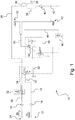
- Fig. 1 shows a schematic pneumatic circuit diagram of an air brake system according to the invention for a trailer.
- FIG. 1 shows a schematic pneumatic circuit diagram of a pneumatic brake system according to the invention for a trailer, which can be provided in particular for agricultural use. Since such a trailer or an agricultural trailer typically does not have any suspension on its two or three axles, there is no essential manipulated variable for controlling a normally used automatically load-dependent brake force regulator, as is also to be used in the present brake system. However, here it is combined with an additional manually adjustable brake force regulator, with the help of which the non-existent manipulated variable can be simulated manually.
- the entire brake system is identified by reference number 10.
- the trailer itself is not recognizable in the illustration, nor is the towing vehicle with which the trailer can be coupled mechanically, hydraulically and pneumatically, and typically also electrically.
- the remaining components that are on the circuit diagram are recognizable, are explained below in their function and in their interaction with one another.
- the reference number 12 in the Fig. 1 a control pressure connection, which in practice is often referred to as "yellow coupling head" and is accordingly colored.
- the pneumatic brake system 10 is supplied with control pressure 14, which is used to actuate the wheel brake valves explained in more detail below.
- the control pressure line 16 leads via an air filter 18 to a control pressure connection 20 on a trailer brake valve designated here with the reference number 22.
- a second pressure connection 24 which functions as a supply pressure connection 24 and is also referred to as such in the wider context.
- this supply pressure connection 24 is also referred to as "coupling head red" and can be marked accordingly in color.
- supply pressure 28 is supplied via a supply pressure line 26, in which an air filter 18 can also be located.
- a pressure vessel 30 is fed and filled.
- Both the control pressure 14 and the supply pressure 28 are normally supplied by a towing vehicle, in particular via connecting lines with which a pneumatic connection to the braking system of the towing vehicle is established.
- the supply pressure line 26 is guided via a release valve 32 for releasing the service brake when the control pressure connection 12 is disconnected and the supply pressure connection 24 is disconnected Fig. 1 is switched to passage so that the supply pressure 28 is led directly to the pressure vessel 30 via a supply pressure connection 34 on the trailer brake valve 22. In this way, when the supply pressure 28 is present, the pressure brake 30 is filled by the trailer brake valve 22 via its supply pressure connection 34.
- a release valve 32 for releasing the service brake when the control pressure connection 12 is disconnected and the supply pressure connection 24 is disconnected Fig. 1 is switched to passage so that the supply pressure 28 is led directly to the pressure vessel 30 via a supply pressure connection 34 on the trailer brake valve 22.
- the pressure brake 30 is filled by the trailer brake valve 22 via its supply pressure connection 34.
- an optional test connection 36 and to a drainage valve 38 on the pressure vessel 30 for the sake of completeness, reference is made to an optional test connection 36 and to a drainage valve 38 on the pressure vessel 30.
- a branch line 44 branches off from the supply pressure line 26 in the vicinity of the pressure container 30, in which there is a manually adjustable brake force regulator 46 (or generally pressure limiting valve), with the aid of which the effective control pressure for the load-dependent brake force regulator 48 can be manually adjusted.
- the braking force regulator 46 can be adjusted, for example, between several switching positions, so that the correct braking pressure can be set for the loading condition of the machine.
- the branch line 44 in which the manually adjustable brake force regulator 46 is located, opens into a known, automatically load-dependent brake force regulator 48, a so-called pneumatic ALB 48, the output line 50 of which leads to the brake cylinders 52 of an axle of the trailer.
- the Fig. 1 only two brake cylinders 52 of one axle of the trailer, which can optionally have two or three axles, each with the same type of brake cylinder 52 assigned to the wheels of all axles, which can be acted upon in a corresponding manner by the ALB 48 with variably adjustable brake pressure.
- the brake cylinders 52 ensure that the wheel brakes of the trailer (not shown here) are actuated evenly and as a function of the respective control pressure.
- the manually adjustable brake force regulator 46 acts as a pressure limiting valve for the control pressure of the pneumatically controlled automatic load control valve (throttle or servo valve), since it is connected upstream of the automatically load-dependent brake force regulator 48 and thus the brake pressure which can be predetermined by the latter, depending on the manual setting lowered if necessary.
- the manually adjustable brake force controller 46 combined in this way with the automatically load-dependent brake force controller 48 and connected on the input side to the supply pressure line 26 of the pressure container 30, a spring pressure of a trailer with non-spring-loaded axles (not shown here) can be simulated due to the trailer used.
- the trailer intended in particular for agricultural use which typically has no suspension on its one axle or on its two or three axles, can be used in the braking system according to the invention due to this structural deviation from goods transport trailers, such as are used for road-bound goods transport 10 used automatically load-dependent brake force controller 48 deliver a meaningful manipulated variable, as normally derived and tapped from the spring pressure of a bellows can be provided, for example, if the trailer were equipped with air suspension with bellows.
- the automatically load-dependent brake force regulator 48 is combined in the manner shown with the additionally upstream manually adjustable brake force regulator 46, with the aid of which the manipulated variable 54 that cannot be derived from the pneumatic pressure of the bellows of the loaded or unloaded trailer can be simulated manually.
- This input manipulated variable 54 can be recognized as the output pressure of the manually adjustable brake force regulator 46, which is made available to the ALB 48 in order to control the brake cylinders 52 in the desired manner.
Landscapes
- Engineering & Computer Science (AREA)
- Transportation (AREA)
- Mechanical Engineering (AREA)
- Regulating Braking Force (AREA)
- Braking Systems And Boosters (AREA)
Abstract
Description
- Die vorliegende Erfindung betrifft ein pneumatisches, hydraulisches oder ähnliches Bremssystem, einen damit ausgestatteten Anhänger sowie einen landwirtschaftlichen Zugverbund, umfassend eine Zugmaschine und wenigstens einen damit gekoppelten Anhänger mit pneumatischem, hydraulischem oder ähnlichem Bremssystem.
- Im Zusammenhang mit landwirtschaftlichen Logistikaufgaben sind die unterschiedlichsten Transportfahrten zu bewältigen, die naturgemäß in vielen Fällen auf öffentlichen Straßen stattzufinden haben. Solche Transportfahrten können sowohl Überführungsfahrten für selbstfahrende oder an eine landwirtschaftliche Zugmaschine angehängte Arbeitsmaschinen. Vieler dieser Transportfahrten sind jedoch Lastentransporte, bei denen bspw. Feldfrüchte nach ihrer Ernte vom Acker zu vorgesehenen Lagerstätten oder zur Weiterverarbeitung transportiert werden, oder bei denen auszubringendes Saat- oder Pflanzgut, zu verteilender Dünger oder auszubringendes Pflanzenschutzmittel in Tanks oder Vorratsbehältern mitgeführt und zum Bestimmungsort gebracht werden soll.
- Typische landwirtschaftliche Anhänger können Transportanhänger wie etwa Ladewagen, Gülletransport- und Verteilanhänger, gezogene Handelsdüngerstreuer o dgl. oder auch Arbeitsanhänger wie große gezogene Pflüge, abmontierte Schneidwerke von Mähdreschern oder Feldhäckslern, gezogene Sämaschinen oder zahlreiche andere landwirtschaftliche Arbeitsmaschinen sein.
- Während in der entfernteren Vergangenheit nicht nur die Maschinen- und Fahrzeuggewichte vergleichsweise gering und zudem die Fahrgeschwindigkeiten bei diesen Transportfahrten auf der Straße noch kaum mehr als etwa 20 bis maximal 25 km/h betrugen, haben nicht nur die Fahrzeuge und Anhänger zunehmend an Größe und Gewicht zugelegt. Auch die mit modernen landwirtschaftlichen Fahrzeugen erzielbaren Fahrgeschwindigkeiten liegen inzwischen weitaus höher als in der Vergangenheit. Alle diese Faktoren tragen gemeinsam dazu bei, dass an die Leistungsfähigkeit und Zuverlässigkeit der heute verwendeten Bremssysteme deutlich höhere Anforderungen gestellt werden müssen, als dies in der Vergangenheit der Fall war.
- Während Anhänger, die mit kleinen Achslasten und die mit relativ niedriger Fahrgeschwindigkeit bewegt werden, auch ohne eigene Bremssysteme betrieben werden können, da die notwendige Verzögerungen durch das Bremsen des Zugfahrzeuges erreicht wird, ist dies bei höheren Fahrgeschwindigkeiten und/oder größeren Achs- bzw. Anhängelasten des Anhängers keine sinnvolle Option, da hierbei die Gefahr besteht, die Betriebsbremsen des Zugfahrzeuges zu überlasten. Zudem besteht die Gefahr, dass es bei höheren Achs- und Anhängelasten zu einem Überschieben der Zugmaschine kommt, woraus eine erhebliche Unfallgefahr resultiert.
- Im Nutzfahrzeugbau sind pneumatische Bremssysteme gebräuchlich, die über Bremskraftsteller zur beladungsabhängigen Variation des Bremsdrucks verfügen. Solche Bremskraftsteller werden auch im landwirtschaftlichen Transportwesen eingesetzt. Technische Bedingung hierfür ist allerdings, dass am Fahrzeug eine Möglichkeit vorhanden ist, die eine technische Ermittlung des Beladungsstandes erlaubt. Dies erfolgt in der Regel durch das Abgreifen der Komprimierung der Fahrzeugfederung oder ähnliches. Die Verwendung einer Federung ist allerdings bei bestimmten Typen von Arbeitsmaschinen wie z.B. von Sämaschinen technisch nicht möglich bzw. sinnvoll. Zudem kann auf keine andere Möglichkeit zurückgegriffen werden, den Beladungszustand abzugreifen, da hierdurch z.B. die Dichtigkeit von Behältern von Feldspritzen negativ beeinflusst werden kann. Da bei Anhängern ohne Fahrwerksfedern eine Eingangsstellgröße für einen herkömmlichen automatisch lastabhängigen Bremskraftregler fehlt, bleibt als sinnvolle Option der Einsatz eines bekannten herkömmlichen Bremskraftstellers, der allerdings einer manuellen Vorgabe des Beladungszustandes bedarf, insbesondere um eine praktikable Begrenzung der Bremskraft bei geringerer Beladung als der maximal zulässigen Beladung oder bei leerem Anhänger zu erreichen.
- Ein solcher Bremskraftsteller funktioniert prinzipiell wie ein Druckbegrenzungsventil, d.h. er schneidet den eingesteuerten Druck bei einem bestimmten Wert ab, damit die Räder des gering beladenen oder leeren Anhängers nicht zum Überbremsen neigen. Bei voll beladenem Anhänger kann der Bremskraftsteller seinen Zweck erfüllen, da das Anhängerbremsventil die Bremsintensität steuert und der durch manuelle Vorgabe in seinem maximalen Wert veränderliche Bremskraftsteller bedarfsweise den maximalen Bremsdruck begrenzt, um das unerwünschte und der Fahrstabilität abträgliche Überbremsen der Anhängerräder zu verhindern.
- Probleme können insbesondere dann entstehen, wenn der Anhänger gering beladen oder leer, wobei die entsprechende manuelle Einstellung des Bremskraftstellers gewählt ist, und wenn bei einer solchen Einstellung das Zugfahrzeug mit deutlich geringerer als maximal möglicher Verzögerung abgebremst wird, d.h. wenn der Fahrer die Bremse nur mit mittlerem oder geringerem Pedaldruck betätigt. Da bei einer solchen Bremsvorgabe des Fahrers der ausgesteuerte Bremsdruck des Anhängerbremsventils sich immer im Verhältnis zum Vorratsdruck regelt und der Bremskraftsteller den Druck abschneidet, kann es leicht zum Überbremsen oder zum Blockieren der Räder kommen. Somit besteht jederzeit das Risiko, dass bei Bremsungen mit geringerer Intensität keine Abbremsung des Anhängers innerhalb anzustrebender Grenzen möglich ist. Andererseits können insbesondere ungebremste Anhänger oder solche mit ungenauer Einstellung der Bremskraftsteller bei stärkeren Bremsungen auf das Zugfahrzeug "aufschieben".
- Diese Bremswertbereiche, die bei unterschiedlichen Bremsintensitäten erreicht werden sollen, werden auch als einzuhaltende Bremsbänder bezeichnet. Genauer gesagt, bezeichnet ein Bremsband eine Vorgabe der Bandbreite für den Druckanstieg im Bremssystem in Abhängigkeit von der Verzögerung.
- Nicht nur die höheren Anhängermassen und Fahrgeschwindigkeiten führen zu erhöhten Anforderungen. Auch Kompatibilitäten müssen beachtet werden, denn nicht alle älteren Zugmaschinen lassen sich mit neueren Anhängern problemlos betreiben, was auch umgekehrt - neue Zugmaschine und älterer Anhänger - gilt. Entsprechend der geltenden EU-Verordnung 167/2013 sowie der darauf Bezug nehmenden Verordnung (EU) 2015/68 über die Bremsanlagen (RVBR) müssen die Bremsanlagen von Traktoren und Anhängefahrzeugen bestimmte Kriterien erfüllen, womit nicht zuletzt eine erhöhte Verkehrssicherheit angestrebt wird. Entsprechend dieser aktuell geltenden europäischen Bestimmungen wurde das Bremsband, die Vorgabe der Bandbreite für den Druckanstieg in Abhängigkeit von der Verzögerung, neu festgelegt. Ein wichtiger Aspekt, der hierbei beachtet werden muss, liegt darin, dass dieses Bremsband entsprechend der geltenden Verordnung grundsätzlich auf Anhänger mit einer Eignung für Geschwindigkeiten von mindestens 40 km/h oder darüber ausgelegt ist.
- Grundsätzlich könnte mit einem elektronischen System zur Verhinderung des Blockierens von Rädern beim stärkeren Bremsen, einem sog. EBS-Bremssystem, das unerwünschte Blockieren der Räder des Anhängers verhindert werden, womit die gewünschte Sicherstellung der Fahrsicherheit unter weitgehend allen in der Praxis auftretenden Betriebsbedingungen erreicht wäre.
- Da allerdings solche elektronischen EBS-Bremssysteme in aller Regel relativ kostenintensiv, aufgrund der unverzichtbaren Systemintegration schwer nachzurüsten und zudem im landwirtschaftlichen Einsatz aufgrund der notwendigen Sensorkomponenten relativ störungsanfällig sind, hat es sich die vorliegende Erfindung zur Aufgabe gemacht, ein vergleichsweise einfach aufgebautes und damit auch kostengünstig realisierbares System für pneumatische Anhängerbremsen bzw. ein pneumatisch arbeitendes Anhängerbremssystem zur Verfügung zu stellen, das gegenüber bekannten pneumatischen Bremssystemen nur weniger zusätzlicher Komponenten bedarf, so dass es bedarfsweise leicht und mit geringem Montageaufwand bei bestehenden pneumatisch arbeitenden Bremssystemen nachgerüstet werden kann.
- Diese Aufgabe wird mit den Gegenständen der unabhängigen Ansprüche gelöst. Merkmale vorteilhafter Weiterbildungen der Erfindung lassen sich den jeweiligen abhängigen Ansprüchen entnehmen.
- Zur Lösung der genannten Aufgabe schlägt die vorliegende Erfindung eine mit pneumatischem Druck arbeitende Bremsanlage für einen Anhänger mit den Merkmalen des unabhängigen Anspruchs vor, wobei diese Bremsanlage insbesondere für einen landwirtschaftlich einsetzbaren oder eingesetzten Anhänger vorgesehen sein kann.
- Bei dem erfindungsgemäßen Bremssystem ist ein automatisch lastabhängiger Bremskraftregler zur bremskraftabhängigen Vorgabe einer Betätigungskraft von wenigstens zwei Rädern einer Anhängerachse zugeordneten Bremszylindern vorgesehen. Hierbei kann eine Eingangsstellgröße zur lastabhängigen Variation und/oder Drosselung eines Steuerdrucks der Bremszylinder manuell vorgegeben werden, insbesondere in Abhängigkeit von einem Beladungszustand des Anhängers. Da der Anhänger, bei dem das Bremssystem eingesetzt wird, normalerweise über keine Federung verfügt, fehlt eine herkömmlicherweise vorhandene Eingangsstellgröße für den automatisch lastabhängigen Bremskraftregler, wie sie bspw. aus den Druckwerten von Federbälgen oder der Komprimierung der Achsfederung gefederter Anhänger abgeleitet werden könnte.
- Stattdessen ist bei der erfindungsgemäßen Bremsanlage dem automatisch lastabhängigen Bremskraftregler ein manuell verstellbarer Bremskraftregler oder allgemein ein Druckregelventil vorgeschaltet, der eine manuell einstellbare Variation, insbesondere variable Drosselung der Eingangsstellgröße ermöglicht. Diese Eingangsstellgröße simuliert einen Federdruck eines - hier nicht vorhandenen - Federelements wie bspw. eines Faltenbalges und gibt dem automatisch lastabhängigen Bremskraftregler, dem sog. ALB einen simulierten Federungsdruck durch, der naturgemäß bei reduzierter Beladung geringer ist als bei voller Beladung. Mit Hilfe des gegenüber bekannten Bremsanlagen unverändert vorhandenen automatisch lastabhängigen Bremskraftreglers, dem jedoch nun erfindungsgemäß ein manuell verstellbarer Bremskraftregler vorgeschaltet ist, kann der Anhänger auch bei unterschiedlich starken Bremsungen jeweils im vorgeschriebenen Bremsband bleiben, ohne dass es zu ungewollten und der Fahrsicherheit abträglichen Blockierungen der Räder aufgrund nicht auf die Beladung abgestimmter Bremsdrücke kommen kann.
- Die Eingangsstellgröße zur Ansteuerung des automatisch lastabhängigen Bremskraftreglers ist mittels des vorgeschalteten manuell verstellbaren Bremskraftreglers oder allgemein mittels des Druckregelventils variierbar. Im Interesse eines einfachen Aufbaus des pneumatischen Bremssystems kann insbesondere vorgesehen sein, dass der manuell verstellbare Bremskraftregler in einer Zweigleitung angeordnet ist, die über einen Vorratsdruck der Bremsanlage gespeist ist.
- Eine weitere Variante zur manuellen Einstellung des Bremsdrucks besteht darin, ein ALB mit Gestänge zu verwenden und den notwendigen Bremshebelweg manuell durch eine verstellbare oder fest fixierbare Wegbegrenzung einzustellen bzw. zu begrenzen.
- Eine sinnvolle Auslegung der Bremsanlage kann bspw. vorsehen, dass der oberhalb von vier bar liegende Vorratsdruck mittels des manuell verstellbaren Bremskraftreglers auf einen Steuer- oder Schaltdruck zwischen etwa zwei bis etwa vier bar reduziert werden kann.
- Die vorliegende Erfindung bezieht sich weiterhin auf einen landwirtschaftlichen Lastenanhänger oder auf einen ähnlichen oder vergleichbaren Anhänger, der über mindestens eine Achse und mindestens ein gebremstes Rad verfügt, und der mit einer mit pneumatischem Druck oder mit hydraulischem Druck arbeitenden Bremsanlage gemäß einer der zuvor beschriebenen Ausführungsvarianten ausgestattet ist. Wahlweise kann dieser landwirtschaftliche Lastenanhänger auch über mindestens zwei Achsen und mindestens vier gebremste Räder verfügen. Zudem bietet der Einsatz des erfindungsgemäßen Bremssystems besonders dann die erwähnten Vorzüge, wenn es sich bei dem landwirtschaftlichen Lastenanhänger um einen solchen handelt, bei dem die wenigstens eine Achse gegenüber einem Aufbau ungefedert ist, da hier die üblicherweise vorhandene Eingangsgröße für die beladungsabhängige und lastabhängige Variation des Bremsdrucks fehlt.
- Schließlich umfasst die Erfindung auch einen landwirtschaftlichen Zugverbund, umfassend eine landwirtschaftliche Zugmaschine und einen daran angehängten und damit mechanisch sowie pneumatisch gekoppelten landwirtschaftlichen Lastenanhänger, wie er zuvor definiert wurde, der mit einer mit pneumatischem Druck oder mit hydraulischem Druck arbeitenden Bremsanlage gemäß einer der zuvor beschriebenen Ausführungsvarianten ausgestattet ist.
- Im Folgenden sollen Ausführungsbeispiele die Erfindung und ihre Vorteile anhand der beigefügten Zeichnung näher erläutern.
-
Fig. 1 zeigt ein schematisches Pneumatikschaltbild einer erfindungsgemäßen Druckluftbremsanlage für einen Anhänger. - Die dargestellte Ausführungsform soll lediglich ein praktisch einsetzbares Beispiel darstellen, wie die erfindungsgemäße Druckluftbremsanlage ausgestaltet sein kann, soll aber keine abschließende Begrenzung darstellen.
- Die einzige
Fig. 1 zeigt ein schematisches Pneumatikschaltbild einer erfindungsgemäßen Druckluftbremsanlage für einen Anhänger, der insbesondere für einen landwirtschaftlichen Einsatz vorgesehen sein kann. Da ein solcher Anhänger bzw. ein landwirtschaftlich eingesetzter Anhänger typischerweise über keine Federung an seinen zwei oder drei Achsen verfügt, fehlt eine wesentliche Stellgröße zur Ansteuerung eines normalerweise eingesetzten automatisch lastabhängigen Bremskraftreglers, wie er auch im vorliegenden Bremssystem eingesetzt werden soll. Allerdings wird er hier mit einem zusätzlichen manuell verstellbaren Bremskraftregler kombiniert, mit dessen Hilfe die nicht vorhandene Stellgröße auf manuellem Wege simuliert werden kann. - Die gesamte Bremsanlage ist hierbei mit der Bezugsziffer 10 gekennzeichnet. Der Anhänger selbst ist in der Darstellung nicht erkennbar, ebenso wenig wie das Zugfahrzeug, mit dem der Anhänger mechanisch, hydraulisch und pneumatisch sowie typischerweise auch elektrisch gekoppelt werden kann. Die übrigen Komponenten, die auf dem Schaltbild erkennbar sind, werden nachfolgend in ihrer Funktion sowie in ihrer Zusammenwirkung untereinander erläutert.
- Die Bezugsziffer 12 bezeichnet in der
Fig. 1 einen Steuerdruckanschluss, der in der Praxis oftmals auch als "Kupplungskopf gelb" bezeichnet und entsprechend farbig gekennzeichnet ist. Über diesen ersten Druckanschluss 12 wird die pneumatische Bremsanlage 10 mit Steuerdruck 14 versorgt, welcher der Betätigung der nachfolgend näher erläuterten Radbremsventile dient. Die Steuerdruckleitung 16 führt über einen Luftfilter 18 zu einem Steuerdruckanschluss 20 an einem hier mit der Bezugsziffer 22 bezeichneten Anhänger-Bremsventil. - Eine weitere pneumatische Schnittstelle der Bremsanlage 10 ist durch einen zweiten Druckanschluss 24 gebildet, der als Vorratsdruckanschluss 24 fungiert und im weiteren Zusammenhang auch als solcher bezeichnet wird. In der Praxis wird dieser Vorratsdruckanschluss 24 auch als "Kupplungskopf rot" bezeichnet und kann entsprechend farbig gekennzeichnet sein. Über den Vorratsdruckanschluss 24 wird über eine Vorratsdruckleitung 26, in der sich ebenfalls ein Luftfilter 18 befinden kann, Vorratsdruck 28 zugeführt, mit dem u.a. ein Druckbehälter 30 gespeist und befüllt wird.
- Sowohl der Steuerdruck 14 als auch der Vorratsdruck 28 werden normalerweise von einem Zugfahrzeug geliefert, insbesondere über Anschlussleitungen, mit denen eine pneumatische Verbindung zum Bremssystem des Zugfahrzeuges hergestellt wird.
- Die Vorratsdruckleitung 26 ist über ein Löseventil 32 zum Lösen der Betriebsbremse bei abgekoppeltem Steuerdruckanschluss 12 und abgekoppeltem Vorratsdruckanschluss 24 geführt, das in der Schaltstellung der
Fig. 1 auf Durchgang geschaltet ist, so dass der Vorratsdruck 28 über einen Vorratsdruckanschluss 34 am Anhänger-Bremsventil 22 direkt zum Druckbehälter 30 geführt ist. Auf diese Weise wird bei anliegendem Vorratsdruck 28 durch das Anhängerbremsventil 22 über dessen Vorratsdruckanschluss 34 der Druckbehälter 30 befüllt. Der Vollständigkeit halber sei auf einen optionalen Prüfanschluss 36 sowie auf ein Entwässerungsventil 38 am Druckbehälter 30 hingewiesen. Sofern im Druckbehälter 30 temporär ein für die Bremsung ausreichend hoher pneumatischer Druck aufgebaut sein sollte, kann dieser über ein Überströmventil 40 und über die hier so bezeichnete Überströmleitung 42 abströmen, wobei dieser Überdruck einer weiteren Verwendung zugeführt werden kann, was hier jedoch nicht näher betrachtet werden soll. - Weiterhin zweigt von der Vorratsdruckleitung 26 in Nähe des Druckbehälters 30 eine Zweigleitung 44 ab, in der sich ein manuell verstellbarer Bremskraftregler 46 (oder allgemein Druckbegrenzungsventil) befindet, mit dessen Hilfe der effektive Steuerdruck für den lastabhängigen Bremskraftregler 48 manuell verstellt werden kann. Je nach Beladungszustand des Anhängers kann der Bremskraftregler 46 bspw. zwischen mehreren Schaltstellungen verstellt werden, so dass für den Beladungszustand der Maschine der korrekte Bremsdruck eingestellt werden kann. Die Zweigleitung 44, in der sich der manuell verstellbare Bremskraftregler 46 befindet, mündet in einem an sich bekannten automatisch lastabhängigen Bremskraftregler 48, einem sog. pneumatischen ALB 48, dessen Ausgangsleitung 50 zu den Bremszylindern 52 einer Achse des Anhängers führt.
- Aus Vereinfachungsgründen zeigt die
Fig. 1 lediglich zwei Bremszylinder 52 einer Achse des Anhängers, der wahlweise zwei oder drei Achsen mit jeweils den Rädern aller Achsen zugeordneten gleichartigen Bremszylindern 52 aufweisen kann, die in entsprechender Weise vom ALB 48 mit variabel einstellbarem Bremsdruck beaufschlagt werden können. Die Bremszylinder 52 sorgen für eine gleichmäßige und vom jeweiligen Steuerdruck abhängige Betätigung der Radbremsen des Anhängers (hier nicht gezeigt). - Der manuell einstellbare Bremskraftregler 46 wirkt in der hier gewählten Verschaltung als Druckbegrenzungsventil für den Steuerdruck des pneumatisch gesteuerten automatischen Lastregelventils (Drossel- oder Servoventil), da er dem automatisch lastabhängigen Bremskraftregler 48 vorgeschaltet ist und somit den von diesem vorgebbaren Bremsdruck in Abhängigkeit von der manuellen Einstellung bedarfsweise absenkt. Mit Hilfe des solchermaßen mit dem automatisch lastabhängigen Bremskraftregler 48 kombinierten manuell einstellbaren Bremskraftreglers 46, der eingangsseitig mit der Vorratsdruckleitung 26 des Druckbehälters 30 verbunden ist, kann ein Federdruck eines hier aufgrund des eingesetzten Anhängers mit nicht gefederten Achsen (hier nicht dargestellt) simuliert werden.
- Der insbesondere für einen landwirtschaftlichen Einsatz vorgesehene Anhänger, der typischerweise über keine Federung an seiner einen Achse oder an seinen zwei oder drei Achsen verfügt, kann durch diese bauliche Abweichung von Gütertransportanhängern, wie sie etwa für den straßengebundenen Gütertransport eingesetzt werden, dem in der erfindungsgemäßen Bremsanlage 10 eingesetzten automatisch lastabhängigen Bremskraftregler 48 eine sinnvolle Stellgröße liefern, wie sie normalerweise aus dem Federdruck eines Federbalges hergeleitet und abgegriffen werden kann, sofern der Anhänger bspw. mit einer Luftfederung mit Federbälgen ausgestattet wäre. Stattdessen wird der automatisch lastabhängige Bremskraftregler 48 in der gezeigten Weise mit dem zusätzlich vorgeschalteten manuell verstellbaren Bremskraftregler 46 kombiniert, mit dessen Hilfe die nicht aus dem pneumatischen Druck des Federbalges des belasteten oder nicht belasteten Anhängers ableitbare Stellgröße 54 auf manuellem Wege simuliert werden kann.
- Die
Fig. 1 lässt diese Eingangsstellgröße 54 als Ausgangsdruck des manuell verstellbaren Bremskraftreglers 46 erkennen, die dem ALB 48 zur Verfügung gestellt wird, um die Bremszylinder 52 in gewünschter Weise anzusteuern. - Im Ergebnis kann mittels der gezeigten Ausführungsvariante der erfindungsgemäßen Bremsanlage 10 gewährleistet werden, dass durch entsprechende Einstellungen des manuell verstellbaren Bremskraftreglers 46, die sich an der jeweiligen Beladung des Anhängers zu orientieren hat, die Räder des Anhängers auch bei verschieden starken Bremsvorgängen jeweils im vorgeschriebenen Bremsband bleiben.
- Die Erfindung wurde unter Bezugnahme auf eine bevorzugte Ausführungsform beschrieben. Es ist jedoch für einen Fachmann vorstellbar, dass Abwandlungen oder Änderungen der Erfindung gemacht werden können, ohne dabei den Schutzbereich der nachstehenden Ansprüche zu verlassen.
-
- 10
- Bremsanlage, Druckluftbremsanlage, pneumatische Bremsanlage
- 12
- erster Druckanschluss, Steuerdruckanschluss ("Kupplungskopf gelb")
- 14
- Steuerdruck
- 16
- Steuerdruckleitung
- 18
- Luftfilter
- 20
- Steuerdruckanschluss
- 22
- Anhänger-Bremsventil
- 24
- zweiter Druckanschluss, Vorratsdruckanschluss ("Kupplungskopf rot")
- 26
- Vorratsdruckleitung
- 28
- Vorratsdruck
- 30
- Druckbehälter, Druckkessel
- 32
- Löseventil (Feststellbremse)
- 34
- Vorratsdruckanschluss
- 36
- Prüfanschluss (Druckbehälter)
- 38
- Entwässerungsventil (Druckbehälter)
- 40
- Überströmventil
- 42
- Überströmleitung
- 44
- Zweigleitung
- 46
- manuell verstellbarer Bremskraftregler
- 48
- automatisch lastabhängiger Bremskraftregler, ALB
- 50
- Ausgangsleitung
- 52
- Radbremszylinder
- 54
- Stellgröße, Eingangsstellgröße
Claims (9)
- Mit pneumatischem Druck arbeitende Bremsanlage (10) für einen Anhänger, insbesondere für einen landwirtschaftlich einsetzbaren oder eingesetzten Anhänger, bei dem ein automatisch lastabhängiger Bremskraftregler (48) zur bremskraftabhängigen Vorgabe einer Betätigungskraft von wenigstens zwei Rädern einer Anhängerachse zugeordneten Bremszylindern (52) vorgesehen ist, wobei eine Eingangsstellgröße (54) zur lastabhängigen Variation und/oder Drosselung eines Steuerdrucks der Radbremszylinder (52) manuell vorgebbar ist, insbesondere in Abhängigkeit von einem Beladungszustand des Anhängers.
- Bremsanlage (10) nach Anspruch 1, bei welcher dem insbesondere pneumatisch angesteuerten automatisch lastabhängigen Bremskraftregler (48) ein manuell verstellbarer Bremskraftregler (46) oder ein Druckbegrenzungsventil oder dergleichen vorgeschaltet ist, der eine manuell einstellbare Variation, insbesondere eine gestufte oder variable Begrenzung der Eingangsstellgröße (54) ermöglicht.
- Bremsanlage (10) nach Anspruch 2, bei der die Eingangsstellgröße (54) zur Ansteuerung des automatisch lastabhängigen Bremskraftreglers (48) mittels des vorgeschalteten manuell verstellbaren Bremskraftreglers (46) oder des Druckbegrenzungsventils variierbar ist.
- Bremsanlage (10) nach einem der Ansprüche 1 bis 3, bei dem der manuell verstellbare Bremskraftregler (46) oder das Druckbegrenzungsventil in einer Zweigleitung (44) angeordnet ist, die über einen Vorratsdruck (28) der Bremsanlage (10) gespeist ist.
- Bremsanlage (10) nach einem der Ansprüche 1 bis 4, bei dem der Vorratsdruck (28) mittels des manuell verstellbaren Bremskraftreglers (46) auf einen Steuer- oder Schaltdruck manuell auf den benötigten Bremsdruck reduzierbar ist.
- Landwirtschaftlicher Lastenanhänger, der über mindestens eine Achse und mindestens ein gebremstes Rad verfügt, und der mit einer mit pneumatischem Druck arbeitenden Bremsanlage (10) gemäß einem der Ansprüche 1 bis 5 ausgestattet ist.
- Landwirtschaftlicher Lastenanhänger, der über mindestens zwei Achsen und mindestens vier gebremste Räder verfügt, und der mit einer mit pneumatischem Druck arbeitenden Bremsanlage (10) gemäß einem der Ansprüche 1 bis 5 ausgestattet ist.
- Landwirtschaftlicher Lastenanhänger, bei dem die wenigstens eine Achse gegenüber einem Aufbau ungefedert ist, und/oder bei dem keine Möglichkeit vorhanden ist, einen Füllstand oder Beladungszustand des Anhängers automatisch zu erfassen.
- Zugverbund, umfassend eine landwirtschaftliche Zugmaschine und einen daran angehängten und damit mechanisch sowie pneumatisch gekoppelten landwirtschaftlichen Lastenanhänger gemäß einem der Ansprüche 6 bis 8, der mit einer mit pneumatischem Druck arbeitenden Bremsanlage (10) gemäß einem der Ansprüche 1 bis 5 ausgestattet ist.
Applications Claiming Priority (1)
| Application Number | Priority Date | Filing Date | Title |
|---|---|---|---|
| DE102019102136.7A DE102019102136A1 (de) | 2019-01-29 | 2019-01-29 | Bremssystem für einen landwirtschaftlich einsetzbaren Anhänger sowie landwirtschaftlicher Zugverbund, umfassend eine Zugmaschine und wenigstens einen damit gekoppelten Anhänger |
Publications (2)
| Publication Number | Publication Date |
|---|---|
| EP3689690A1 true EP3689690A1 (de) | 2020-08-05 |
| EP3689690B1 EP3689690B1 (de) | 2022-12-14 |
Family
ID=69147543
Family Applications (1)
| Application Number | Title | Priority Date | Filing Date |
|---|---|---|---|
| EP20150703.5A Active EP3689690B1 (de) | 2019-01-29 | 2020-01-08 | Mit pneumatischem druck arbeitende bremsanlage für einen anhänger, landwirtschaftlicher lastenanhänger sowie zugverbund, umfassend eine landwirtschaftliche zugmaschine und einen damit gekoppelten landwirtschaftlichen lastenanhänger |
Country Status (2)
| Country | Link |
|---|---|
| EP (1) | EP3689690B1 (de) |
| DE (1) | DE102019102136A1 (de) |
Families Citing this family (2)
| Publication number | Priority date | Publication date | Assignee | Title |
|---|---|---|---|---|
| DE102021106484A1 (de) * | 2021-03-17 | 2022-09-22 | Amazonen-Werke H. Dreyer SE & Co. KG | Bremssystem und land- und/oder forstwirtschaftliches Anhängerfahrzeug mit einem Bremssystem |
| DE102024209968A1 (de) * | 2024-10-15 | 2026-04-16 | Zf Cv Systems Global Gmbh | Landwirtschaftlicher Fahrzeuganhänger und Verfahren zum beladungsabhängigen Einstellen einer Bremskraft des landwirtschaftlichen Fahrzeuganhängers |
Citations (6)
| Publication number | Priority date | Publication date | Assignee | Title |
|---|---|---|---|---|
| CH307230A (de) * | 1951-05-26 | 1955-05-31 | Lutz Hans Ing Dr | Arbeitsfahrzeug für landwirtschaftliche Zwecke. |
| DE1871081U (de) * | 1961-06-09 | 1963-04-25 | Knorr Bremse Gmbh | Druckluftbremse fuer lastkraftwagenanhaenger. |
| US3416843A (en) * | 1966-12-14 | 1968-12-17 | Berg Mfg & Sales Co | Brake pressure regulator |
| DE3216407A1 (de) * | 1982-03-11 | 1983-09-15 | Wabco Westinghouse Fahrzeugbremsen GmbH, 3000 Hannover | Bremskraftregler fuer druckmittelbetaetigte bremsanlagen |
| DE3639149A1 (de) * | 1986-11-15 | 1988-05-19 | Wabco Westinghouse Fahrzeug | Lastabhaengig steuerbare bremskraftregeleinrichtung |
| DE102006007575A1 (de) * | 2006-02-18 | 2007-08-23 | Deere & Company, Moline | Hydraulische Anordnung |
-
2019
- 2019-01-29 DE DE102019102136.7A patent/DE102019102136A1/de active Pending
-
2020
- 2020-01-08 EP EP20150703.5A patent/EP3689690B1/de active Active
Patent Citations (6)
| Publication number | Priority date | Publication date | Assignee | Title |
|---|---|---|---|---|
| CH307230A (de) * | 1951-05-26 | 1955-05-31 | Lutz Hans Ing Dr | Arbeitsfahrzeug für landwirtschaftliche Zwecke. |
| DE1871081U (de) * | 1961-06-09 | 1963-04-25 | Knorr Bremse Gmbh | Druckluftbremse fuer lastkraftwagenanhaenger. |
| US3416843A (en) * | 1966-12-14 | 1968-12-17 | Berg Mfg & Sales Co | Brake pressure regulator |
| DE3216407A1 (de) * | 1982-03-11 | 1983-09-15 | Wabco Westinghouse Fahrzeugbremsen GmbH, 3000 Hannover | Bremskraftregler fuer druckmittelbetaetigte bremsanlagen |
| DE3639149A1 (de) * | 1986-11-15 | 1988-05-19 | Wabco Westinghouse Fahrzeug | Lastabhaengig steuerbare bremskraftregeleinrichtung |
| DE102006007575A1 (de) * | 2006-02-18 | 2007-08-23 | Deere & Company, Moline | Hydraulische Anordnung |
Also Published As
| Publication number | Publication date |
|---|---|
| EP3689690B1 (de) | 2022-12-14 |
| DE102019102136A1 (de) | 2020-07-30 |
Similar Documents
| Publication | Publication Date | Title |
|---|---|---|
| EP3744590B1 (de) | Bremssystem für einen landwirtschaftlich einsetzbaren anhänger sowie landwirtschaftlicher zugverbund, umfassend eine zugmaschine und wenigstens einen damit gekoppelten anhänger | |
| DE19944873C1 (de) | Steueranlage zum Heben und Senken des Fahrzeugaufbaus von luftgefederten Fahrzeugen mit Niveauregelung | |
| EP2058188B1 (de) | Steueranlage für Kraftfahrzeug-Anhänger mit Betriebsbremse, Feststellbremse und Luftfederung | |
| WO2021094116A1 (de) | Elektropneumatisches steuermodul | |
| DE102012107203B4 (de) | Pneumatische Bremseinrichtung eines Fahrzeugs mit vom Parkbremsventil zwangsgesteuerter Interlock-Einrichtung | |
| EP3386814A1 (de) | Verfahren zum einstellen von bremsdrücken eines fahrzeugs und bremsanlage zur durchführung des verfahrens | |
| DE102011017118A1 (de) | Vorrichtung zur Anpassung des Ist-Reifendrucks wenigstens eines Reifens eines Fahrzeugs an einen aktuellen Soll-Reifendruck während der Fahrt | |
| DE102009011606A1 (de) | Vorrichtung und Verfahren zum Durchführen einer Radstandregelung für Nutzfahrzeuge | |
| DE102011051505C5 (de) | Niveauregelventileinheit mit integriertem Verteiler | |
| EP3774403B1 (de) | Reifendruckregulierungseinrichtung eines luftbereiften off-highway-fahrzeugs | |
| DE2056634C3 (de) | Luftfederung für Tandemachsen von Fahrzeugen mit Niveauregelung und Regelung der Achslastverteilung | |
| DE19706982A1 (de) | Bremsanlage zur Steuerung der Bremsung eines Anhängerfahrzeuges | |
| EP3689690B1 (de) | Mit pneumatischem druck arbeitende bremsanlage für einen anhänger, landwirtschaftlicher lastenanhänger sowie zugverbund, umfassend eine landwirtschaftliche zugmaschine und einen damit gekoppelten landwirtschaftlichen lastenanhänger | |
| EP4259498B1 (de) | Druckluftbremsanlage eines zugfahrzeugs | |
| DE102005002699B4 (de) | Bremsventilanordung | |
| DE102011117882A1 (de) | Ventilanordnung und Verfahren zur Steuerung einer Ventilanordnung | |
| EP3744587B1 (de) | Bremsanlage für eine landwirtschaftliche arbeitsmaschine sowie landwirtschaftlicher zugverbund, umfassend eine zugmaschine und wenigstens eine damit gekoppelte arbeitsmaschine | |
| DE3028472A1 (de) | Steuerung einer luftgefederten, anhebbaren und absenkbaren nachlaufachse eines nutzkraftfahrzeugs | |
| EP3354488A1 (de) | Reifendruckregulierungsanlage | |
| DE102012008002B4 (de) | Pneumatische Einrichtung eines Fahrzeugs, umfassend eine Reifendrucksteuervorrichtung | |
| DE69014487T2 (de) | Druckluftbremsanlage. | |
| DE102018002488A1 (de) | Bremssystem eines Fahrzeugzuges | |
| DE2938089A1 (de) | Hydraulische anhaengerbremse, insbesondere fuer land- forstwirtschaftliche anhaenger | |
| EP3569458B1 (de) | Verfahren zum betreiben eines bremssystems eines landwirtschaftlichen zuges, bremssystem für einen landwirtschaftlichen zug sowie landwirtschaftlicher zug | |
| EP1108570B1 (de) | Luftgefedertes Nutzfahrzeug mit einer angetriebenen Hinterachse und einer dieser beigeordneten Vor- oder Nachlaufachse |
Legal Events
| Date | Code | Title | Description |
|---|---|---|---|
| PUAI | Public reference made under article 153(3) epc to a published international application that has entered the european phase |
Free format text: ORIGINAL CODE: 0009012 |
|
| STAA | Information on the status of an ep patent application or granted ep patent |
Free format text: STATUS: THE APPLICATION HAS BEEN PUBLISHED |
|
| AK | Designated contracting states |
Kind code of ref document: A1 Designated state(s): AL AT BE BG CH CY CZ DE DK EE ES FI FR GB GR HR HU IE IS IT LI LT LU LV MC MK MT NL NO PL PT RO RS SE SI SK SM TR |
|
| AX | Request for extension of the european patent |
Extension state: BA ME |
|
| STAA | Information on the status of an ep patent application or granted ep patent |
Free format text: STATUS: REQUEST FOR EXAMINATION WAS MADE |
|
| 17P | Request for examination filed |
Effective date: 20210126 |
|
| RBV | Designated contracting states (corrected) |
Designated state(s): AL AT BE BG CH CY CZ DE DK EE ES FI FR GB GR HR HU IE IS IT LI LT LU LV MC MK MT NL NO PL PT RO RS SE SI SK SM TR |
|
| REG | Reference to a national code |
Ref country code: DE Ref legal event code: R079 Ref document number: 502020002166 Country of ref document: DE Free format text: PREVIOUS MAIN CLASS: B60T0007200000 Ipc: B60T0013260000 |
|
| RIC1 | Information provided on ipc code assigned before grant |
Ipc: B60T 13/68 20060101ALI20220613BHEP Ipc: B60T 8/18 20060101ALI20220613BHEP Ipc: B60T 7/20 20060101ALI20220613BHEP Ipc: B60T 13/26 20060101AFI20220613BHEP |
|
| GRAP | Despatch of communication of intention to grant a patent |
Free format text: ORIGINAL CODE: EPIDOSNIGR1 |
|
| STAA | Information on the status of an ep patent application or granted ep patent |
Free format text: STATUS: GRANT OF PATENT IS INTENDED |
|
| INTG | Intention to grant announced |
Effective date: 20220727 |
|
| GRAS | Grant fee paid |
Free format text: ORIGINAL CODE: EPIDOSNIGR3 |
|
| GRAA | (expected) grant |
Free format text: ORIGINAL CODE: 0009210 |
|
| STAA | Information on the status of an ep patent application or granted ep patent |
Free format text: STATUS: THE PATENT HAS BEEN GRANTED |
|
| AK | Designated contracting states |
Kind code of ref document: B1 Designated state(s): AL AT BE BG CH CY CZ DE DK EE ES FI FR GB GR HR HU IE IS IT LI LT LU LV MC MK MT NL NO PL PT RO RS SE SI SK SM TR |
|
| REG | Reference to a national code |
Ref country code: GB Ref legal event code: FG4D Free format text: NOT ENGLISH |
|
| REG | Reference to a national code |
Ref country code: CH Ref legal event code: EP |
|
| REG | Reference to a national code |
Ref country code: DE Ref legal event code: R096 Ref document number: 502020002166 Country of ref document: DE |
|
| REG | Reference to a national code |
Ref country code: IE Ref legal event code: FG4D Free format text: LANGUAGE OF EP DOCUMENT: GERMAN |
|
| REG | Reference to a national code |
Ref country code: AT Ref legal event code: REF Ref document number: 1537508 Country of ref document: AT Kind code of ref document: T Effective date: 20230115 |
|
| REG | Reference to a national code |
Ref country code: LT Ref legal event code: MG9D |
|
| REG | Reference to a national code |
Ref country code: NL Ref legal event code: MP Effective date: 20221214 |
|
| PG25 | Lapsed in a contracting state [announced via postgrant information from national office to epo] |
Ref country code: SE Free format text: LAPSE BECAUSE OF FAILURE TO SUBMIT A TRANSLATION OF THE DESCRIPTION OR TO PAY THE FEE WITHIN THE PRESCRIBED TIME-LIMIT Effective date: 20221214 Ref country code: NO Free format text: LAPSE BECAUSE OF FAILURE TO SUBMIT A TRANSLATION OF THE DESCRIPTION OR TO PAY THE FEE WITHIN THE PRESCRIBED TIME-LIMIT Effective date: 20230314 Ref country code: LT Free format text: LAPSE BECAUSE OF FAILURE TO SUBMIT A TRANSLATION OF THE DESCRIPTION OR TO PAY THE FEE WITHIN THE PRESCRIBED TIME-LIMIT Effective date: 20221214 Ref country code: FI Free format text: LAPSE BECAUSE OF FAILURE TO SUBMIT A TRANSLATION OF THE DESCRIPTION OR TO PAY THE FEE WITHIN THE PRESCRIBED TIME-LIMIT Effective date: 20221214 |
|
| PG25 | Lapsed in a contracting state [announced via postgrant information from national office to epo] |
Ref country code: RS Free format text: LAPSE BECAUSE OF FAILURE TO SUBMIT A TRANSLATION OF THE DESCRIPTION OR TO PAY THE FEE WITHIN THE PRESCRIBED TIME-LIMIT Effective date: 20221214 Ref country code: LV Free format text: LAPSE BECAUSE OF FAILURE TO SUBMIT A TRANSLATION OF THE DESCRIPTION OR TO PAY THE FEE WITHIN THE PRESCRIBED TIME-LIMIT Effective date: 20221214 Ref country code: HR Free format text: LAPSE BECAUSE OF FAILURE TO SUBMIT A TRANSLATION OF THE DESCRIPTION OR TO PAY THE FEE WITHIN THE PRESCRIBED TIME-LIMIT Effective date: 20221214 Ref country code: GR Free format text: LAPSE BECAUSE OF FAILURE TO SUBMIT A TRANSLATION OF THE DESCRIPTION OR TO PAY THE FEE WITHIN THE PRESCRIBED TIME-LIMIT Effective date: 20230315 |
|
| PG25 | Lapsed in a contracting state [announced via postgrant information from national office to epo] |
Ref country code: NL Free format text: LAPSE BECAUSE OF FAILURE TO SUBMIT A TRANSLATION OF THE DESCRIPTION OR TO PAY THE FEE WITHIN THE PRESCRIBED TIME-LIMIT Effective date: 20221214 |
|
| PG25 | Lapsed in a contracting state [announced via postgrant information from national office to epo] |
Ref country code: SM Free format text: LAPSE BECAUSE OF FAILURE TO SUBMIT A TRANSLATION OF THE DESCRIPTION OR TO PAY THE FEE WITHIN THE PRESCRIBED TIME-LIMIT Effective date: 20221214 Ref country code: RO Free format text: LAPSE BECAUSE OF FAILURE TO SUBMIT A TRANSLATION OF THE DESCRIPTION OR TO PAY THE FEE WITHIN THE PRESCRIBED TIME-LIMIT Effective date: 20221214 Ref country code: PT Free format text: LAPSE BECAUSE OF FAILURE TO SUBMIT A TRANSLATION OF THE DESCRIPTION OR TO PAY THE FEE WITHIN THE PRESCRIBED TIME-LIMIT Effective date: 20230414 Ref country code: ES Free format text: LAPSE BECAUSE OF FAILURE TO SUBMIT A TRANSLATION OF THE DESCRIPTION OR TO PAY THE FEE WITHIN THE PRESCRIBED TIME-LIMIT Effective date: 20221214 Ref country code: EE Free format text: LAPSE BECAUSE OF FAILURE TO SUBMIT A TRANSLATION OF THE DESCRIPTION OR TO PAY THE FEE WITHIN THE PRESCRIBED TIME-LIMIT Effective date: 20221214 Ref country code: CZ Free format text: LAPSE BECAUSE OF FAILURE TO SUBMIT A TRANSLATION OF THE DESCRIPTION OR TO PAY THE FEE WITHIN THE PRESCRIBED TIME-LIMIT Effective date: 20221214 |
|
| PG25 | Lapsed in a contracting state [announced via postgrant information from national office to epo] |
Ref country code: SK Free format text: LAPSE BECAUSE OF FAILURE TO SUBMIT A TRANSLATION OF THE DESCRIPTION OR TO PAY THE FEE WITHIN THE PRESCRIBED TIME-LIMIT Effective date: 20221214 Ref country code: PL Free format text: LAPSE BECAUSE OF FAILURE TO SUBMIT A TRANSLATION OF THE DESCRIPTION OR TO PAY THE FEE WITHIN THE PRESCRIBED TIME-LIMIT Effective date: 20221214 Ref country code: IS Free format text: LAPSE BECAUSE OF FAILURE TO SUBMIT A TRANSLATION OF THE DESCRIPTION OR TO PAY THE FEE WITHIN THE PRESCRIBED TIME-LIMIT Effective date: 20230414 Ref country code: AL Free format text: LAPSE BECAUSE OF FAILURE TO SUBMIT A TRANSLATION OF THE DESCRIPTION OR TO PAY THE FEE WITHIN THE PRESCRIBED TIME-LIMIT Effective date: 20221214 |
|
| REG | Reference to a national code |
Ref country code: CH Ref legal event code: PL |
|
| REG | Reference to a national code |
Ref country code: DE Ref legal event code: R097 Ref document number: 502020002166 Country of ref document: DE |
|
| PG25 | Lapsed in a contracting state [announced via postgrant information from national office to epo] |
Ref country code: MC Free format text: LAPSE BECAUSE OF FAILURE TO SUBMIT A TRANSLATION OF THE DESCRIPTION OR TO PAY THE FEE WITHIN THE PRESCRIBED TIME-LIMIT Effective date: 20221214 Ref country code: LU Free format text: LAPSE BECAUSE OF NON-PAYMENT OF DUE FEES Effective date: 20230108 |
|
| REG | Reference to a national code |
Ref country code: BE Ref legal event code: MM Effective date: 20230131 |
|
| PLBE | No opposition filed within time limit |
Free format text: ORIGINAL CODE: 0009261 |
|
| STAA | Information on the status of an ep patent application or granted ep patent |
Free format text: STATUS: NO OPPOSITION FILED WITHIN TIME LIMIT |
|
| PG25 | Lapsed in a contracting state [announced via postgrant information from national office to epo] |
Ref country code: LI Free format text: LAPSE BECAUSE OF NON-PAYMENT OF DUE FEES Effective date: 20230131 Ref country code: DK Free format text: LAPSE BECAUSE OF FAILURE TO SUBMIT A TRANSLATION OF THE DESCRIPTION OR TO PAY THE FEE WITHIN THE PRESCRIBED TIME-LIMIT Effective date: 20221214 Ref country code: CH Free format text: LAPSE BECAUSE OF NON-PAYMENT OF DUE FEES Effective date: 20230131 |
|
| 26N | No opposition filed |
Effective date: 20230915 |
|
| PG25 | Lapsed in a contracting state [announced via postgrant information from national office to epo] |
Ref country code: SI Free format text: LAPSE BECAUSE OF FAILURE TO SUBMIT A TRANSLATION OF THE DESCRIPTION OR TO PAY THE FEE WITHIN THE PRESCRIBED TIME-LIMIT Effective date: 20221214 Ref country code: BE Free format text: LAPSE BECAUSE OF NON-PAYMENT OF DUE FEES Effective date: 20230131 |
|
| PG25 | Lapsed in a contracting state [announced via postgrant information from national office to epo] |
Ref country code: IE Free format text: LAPSE BECAUSE OF NON-PAYMENT OF DUE FEES Effective date: 20230108 |
|
| PG25 | Lapsed in a contracting state [announced via postgrant information from national office to epo] |
Ref country code: IT Free format text: LAPSE BECAUSE OF FAILURE TO SUBMIT A TRANSLATION OF THE DESCRIPTION OR TO PAY THE FEE WITHIN THE PRESCRIBED TIME-LIMIT Effective date: 20221214 |
|
| GBPC | Gb: european patent ceased through non-payment of renewal fee |
Effective date: 20240108 |
|
| PG25 | Lapsed in a contracting state [announced via postgrant information from national office to epo] |
Ref country code: GB Free format text: LAPSE BECAUSE OF NON-PAYMENT OF DUE FEES Effective date: 20240108 |
|
| PG25 | Lapsed in a contracting state [announced via postgrant information from national office to epo] |
Ref country code: GB Free format text: LAPSE BECAUSE OF NON-PAYMENT OF DUE FEES Effective date: 20240108 |
|
| REG | Reference to a national code |
Ref country code: DE Ref legal event code: R082 Ref document number: 502020002166 Country of ref document: DE Representative=s name: BENNINGER, JOHANNES, DIPL.-ING., DE |
|
| PG25 | Lapsed in a contracting state [announced via postgrant information from national office to epo] |
Ref country code: BG Free format text: LAPSE BECAUSE OF FAILURE TO SUBMIT A TRANSLATION OF THE DESCRIPTION OR TO PAY THE FEE WITHIN THE PRESCRIBED TIME-LIMIT Effective date: 20221214 |
|
| PG25 | Lapsed in a contracting state [announced via postgrant information from national office to epo] |
Ref country code: BG Free format text: LAPSE BECAUSE OF FAILURE TO SUBMIT A TRANSLATION OF THE DESCRIPTION OR TO PAY THE FEE WITHIN THE PRESCRIBED TIME-LIMIT Effective date: 20221214 |
|
| PGFP | Annual fee paid to national office [announced via postgrant information from national office to epo] |
Ref country code: AT Payment date: 20250417 Year of fee payment: 5 |
|
| PG25 | Lapsed in a contracting state [announced via postgrant information from national office to epo] |
Ref country code: CY Free format text: LAPSE BECAUSE OF FAILURE TO SUBMIT A TRANSLATION OF THE DESCRIPTION OR TO PAY THE FEE WITHIN THE PRESCRIBED TIME-LIMIT; INVALID AB INITIO Effective date: 20200108 |
|
| PG25 | Lapsed in a contracting state [announced via postgrant information from national office to epo] |
Ref country code: HU Free format text: LAPSE BECAUSE OF FAILURE TO SUBMIT A TRANSLATION OF THE DESCRIPTION OR TO PAY THE FEE WITHIN THE PRESCRIBED TIME-LIMIT; INVALID AB INITIO Effective date: 20200108 |
|
| PG25 | Lapsed in a contracting state [announced via postgrant information from national office to epo] |
Ref country code: TR Free format text: LAPSE BECAUSE OF FAILURE TO SUBMIT A TRANSLATION OF THE DESCRIPTION OR TO PAY THE FEE WITHIN THE PRESCRIBED TIME-LIMIT Effective date: 20221214 |
|
| REG | Reference to a national code |
Ref country code: DE Ref legal event code: R081 Ref document number: 502020002166 Country of ref document: DE Owner name: HORSCH LEEB APPLICATION SYSTEMS SE & CO. KG, DE Free format text: FORMER OWNER: HORSCH LEEB APPLICATION SYSTEMS GMBH, 94405 LANDAU, DE |
|
| REG | Reference to a national code |
Ref country code: AT Ref legal event code: MM01 Ref document number: 1537508 Country of ref document: AT Kind code of ref document: T Effective date: 20250108 |
|
| PGFP | Annual fee paid to national office [announced via postgrant information from national office to epo] |
Ref country code: DE Payment date: 20260120 Year of fee payment: 7 |
|
| PG25 | Lapsed in a contracting state [announced via postgrant information from national office to epo] |
Ref country code: AT Free format text: LAPSE BECAUSE OF NON-PAYMENT OF DUE FEES Effective date: 20250108 |
|
| PGFP | Annual fee paid to national office [announced via postgrant information from national office to epo] |
Ref country code: FR Payment date: 20260128 Year of fee payment: 7 |