EP3689550A2 - Powered fastener driver - Google Patents
Powered fastener driver Download PDFInfo
- Publication number
- EP3689550A2 EP3689550A2 EP20154512.6A EP20154512A EP3689550A2 EP 3689550 A2 EP3689550 A2 EP 3689550A2 EP 20154512 A EP20154512 A EP 20154512A EP 3689550 A2 EP3689550 A2 EP 3689550A2
- Authority
- EP
- European Patent Office
- Prior art keywords
- fastener
- driver
- driver blade
- nosepiece
- received
- Prior art date
- Legal status (The legal status is an assumption and is not a legal conclusion. Google has not performed a legal analysis and makes no representation as to the accuracy of the status listed.)
- Granted
Links
Images





Classifications
-
- B—PERFORMING OPERATIONS; TRANSPORTING
- B25—HAND TOOLS; PORTABLE POWER-DRIVEN TOOLS; MANIPULATORS
- B25C—HAND-HELD NAILING OR STAPLING TOOLS; MANUALLY OPERATED PORTABLE STAPLING TOOLS
- B25C1/00—Hand-held nailing tools; Nail feeding devices
- B25C1/04—Hand-held nailing tools; Nail feeding devices operated by fluid pressure, e.g. by air pressure
- B25C1/041—Hand-held nailing tools; Nail feeding devices operated by fluid pressure, e.g. by air pressure with fixed main cylinder
-
- B—PERFORMING OPERATIONS; TRANSPORTING
- B25—HAND TOOLS; PORTABLE POWER-DRIVEN TOOLS; MANIPULATORS
- B25C—HAND-HELD NAILING OR STAPLING TOOLS; MANUALLY OPERATED PORTABLE STAPLING TOOLS
- B25C5/00—Manually operated portable stapling tools; Hand-held power-operated stapling tools; Staple feeding devices therefor
- B25C5/16—Staple-feeding devices, e.g. with feeding means, supports for staples or accessories concerning feeding devices
- B25C5/1637—Supports for the staples being fed
-
- B—PERFORMING OPERATIONS; TRANSPORTING
- B25—HAND TOOLS; PORTABLE POWER-DRIVEN TOOLS; MANIPULATORS
- B25C—HAND-HELD NAILING OR STAPLING TOOLS; MANUALLY OPERATED PORTABLE STAPLING TOOLS
- B25C1/00—Hand-held nailing tools; Nail feeding devices
- B25C1/06—Hand-held nailing tools; Nail feeding devices operated by electric power
-
- B—PERFORMING OPERATIONS; TRANSPORTING
- B25—HAND TOOLS; PORTABLE POWER-DRIVEN TOOLS; MANIPULATORS
- B25C—HAND-HELD NAILING OR STAPLING TOOLS; MANUALLY OPERATED PORTABLE STAPLING TOOLS
- B25C5/00—Manually operated portable stapling tools; Hand-held power-operated stapling tools; Staple feeding devices therefor
- B25C5/10—Driving means
- B25C5/15—Driving means operated by electric power
Definitions
- the present invention relates to powered fastener drivers, and more particularly to a driver blade and nosepiece for use with a powered fastener driver.
- fastener drivers known in the art for driving fasteners (e.g., nails, tacks, staples, etc.) into a workpiece.
- fastener drivers operate utilizing various means known in the art (e.g., compressed air generated by an air compressor, electrical energy, a flywheel mechanism, etc.) to drive a driver blade from a top-dead-center position to a bottom-dead-center position.
- the invention provides, in one aspect, a fastener driver including a housing, a cylinder disposed within the housing, a piston positioned and moveable within the cylinder, a nosepiece at least partially defining a fastener driving track through which fasteners are driven, and a driver blade attached to the piston and moveable with the piston to drive the fasteners through the fastener driving track.
- the driver blade includes an axial guiding projection for guiding the driver blade within the nosepiece. The projection terminates before a distal end of the driver blade.
- the axial guiding projection may be oriented parallel with a longitudinal axis of the driver blade.
- the axial guiding projection may extend from the driver blade in a direction transverse to the longitudinal axis.
- the nosepiece may include a recess extending along a length of the nosepiece, and the recess may be configured to receive the axial guiding projection.
- the nosepiece may include a longitudinal guide groove in which the fasteners are received, and wherein the longitudinal guide groove at least partially defines the fastener driving track.
- the nosepiece may include parallel guide ribs extending from an interior surface of the nosepiece, thereby defining an extension of the guide groove.
- the recess in which the axial guiding projection of the driver blade is received may extend, or may be positioned, within the longitudinal guide groove and may be between the parallel guide ribs.
- the fastener driving track may be defined at least partially by the longitudinal guide groove and the parallel guide ribs.
- the driver blade may include an elongated recess extending along a surface of the driver blade facing the nosepiece.
- the driver blade may be movable from a first position toward a second position during a fastener driving operation. In the first position of the driver blade, an upper portion of the fastener within the fastener driving track may be received between the parallel guide ribs and a lower portion of the fastener may be received in the guide groove.
- the parallel guide ribs may be at least partially received within the elongated recess in the driver blade.
- a ratio of a length from a crown of one of the fasteners to a distal end of the nosepiece to a total length of the fastener driver may be less than 25%.
- the nosepiece may support approximately 90% of the length of the one of the fasteners.
- a fastener driver including a housing, a cylinder disposed within the housing, a piston positioned and moveable within the cylinder, a driver blade attached to the piston and moveable with the piston from a first position toward a second position during a fastener driving operation, and a nosepiece at least partially defining a fastener driving track through which fasteners are driven by the driver blade.
- the nosepiece includes a longitudinal guide groove in which a fastener is received and parallel ribs extending from an interior surface of the nosepiece, thereby defining an extension of the guide groove.
- the driver blade When the driver blade is in the second position, the driver blade partially overlaps with the guide ribs, thereby allowing a first portion of the fastener to be received in the guide ribs and a lower, second portion of the fastener to be received in the guide groove.
- the longitudinal guide groove may at least partially define the fastener driving track and may be configured to receive a portion of the driver blade.
- the driver blade may include an axial guiding projection for guiding the driver blade within the nosepiece.
- the projection may terminate before a distal end of the driver blade.
- the nosepiece may include a recess extending along a length of the nosepiece.
- the recess may be configured to receive the axial guiding projection.
- the recess in which the axial guiding projection of the driver blade is received may extend, or may be positioned, within the longitudinal guide groove and between the parallel guide ribs.
- the fastener driving track may be defined at least partially by the longitudinal guide groove and the parallel guide ribs.
- the driver blade may include an elongated recess extending along a surface of the driver blade facing the nosepiece.
- an upper portion of the fastener within the fastener driving track may be received between the parallel guide ribs and a lower portion of the fastener may be received in the guide groove.
- the parallel guide ribs may be at least partially received within the elongated recess in the driver blade.
- the first portion of the fastener may be approximately 35% of a length of the fastener, and the second portion of the fastener may be approximately 55% of the length of the fastener.
- a third portion of the fastener may extend beyond a distal end of the parallel guide ribs.
- a ratio of a length from a crown of one of the fasteners to a distal end of the nosepiece to a total length of the fastener driver may be less than 25%.
- the nosepiece may support approximately 90% of the length of the one of the fasteners.
- a fastener driver including a housing, a cylinder disposed within the housing, a piston positioned and moveable within the cylinder, a driver blade attached to the piston and moveable with the piston from a first position toward a second position during a fastener driving operation, and a nosepiece at least partially defining a fastener driving track through which fasteners are driven by the driver blade, wherein when the driver blade is in the second position, the driver blade partially overlaps with a portion of the nosepiece, and a ratio of a length from a crown of one of the fasteners to a distal end of the nosepiece to a total length of the fastener driver is less than 25%.
- the ratio of the length from the crown of one of the fasteners to the distal end of the nosepiece to the total length of the fastener driver may be 22%.
- the nosepiece may support approximately 90% of the length of the one of the fasteners.
- the nosepiece may include a longitudinal guide groove in which a fastener is received, and may include parallel ribs extending from an interior surface of the nosepiece, thereby defining an extension of the guide groove in which the fastener may also be at least partially received.
- the driver blade may include an elongated recess extending along a surface of the driver blade facing the nosepiece. In the first position of the driver blade, an upper portion of the fastener within the fastener driving track may be received between the parallel guide ribs and a lower portion of the fastener may be received in the guide groove. When the driver blade is in the second position, the parallel guide ribs may be at least partially received within the elongated recess in the driver blade.
- a gas spring-powered fastener driver 10 is operable to drive fasteners (e.g., nails, tacks, staples, etc.) held within a magazine 14 into a workpiece.
- the fastener driver 10 includes a cylinder 18.
- a moveable piston (not shown) is positioned within the cylinder 18.
- the fastener driver 10 further includes a driver blade 22 that is attached to the piston and moveable therewith.
- the fastener driver 10 does not require an external source of air pressure, but rather includes pressurized gas in the cylinder 18.
- the fastener driver 10 includes a housing 26 having a cylinder housing portion 30 and a motor housing portion 34 extending therefrom.
- the cylinder housing portion 30 is configured to support the cylinder 18, whereas the motor housing portion 34 is configured to support a motor 38 and a transmission 42 downstream of the motor 38.
- the illustrated housing 26 includes a handle portion 46 extending from the cylinder housing portion 30, and a battery attachment portion 50 coupled to an opposite end of the handle portion 46.
- a battery (not shown) is electrically connectable to the motor 38 for supplying electrical power to the motor 38.
- the handle portion 46 supports a trigger (not shown), which is depressed by a user to initiate a driving cycle of the fastener driver 10.
- the driver blade 22 defines a longitudinal axis 58.
- the driver blade 22 and piston are moveable between a top-dead-center (TDC) or ready position within the cylinder 18, and a bottom-dead-center (BDC) or driven position, along the axis 58.
- the fastener driver 10 further includes a lifter assembly (not shown), which is powered by the motor 38 ( FIG. 1 ), and which is operable to return the driver blade 22 from the driven position to the ready position.
- the fastener driver 10 further includes a nosepiece assembly 62 that receives collated fasteners from the magazine 14 ( FIGS. 2 and 4 ).
- the nosepiece assembly 62 includes a nosepiece 66 and a shear block 70 that collectively define a fastener driving channel or track 80 ( FIGS. 6A, 6B , and 8 ) that guides the fasteners as they are driven into a workpiece by the driver blade 22.
- the shear block 70 further defines an opening (not shown) that permits fasteners to pass from the magazine 14 through the shear block 70 and into the driver track 80.
- the driver blade 22 includes an elongated body 74 having a first planar surface (i.e., a front surface 78) and an opposite, a second planar surface (i.e., a rear surface 82).
- a first edge 86 extends between the front surface 78 and the rear surface 82 along one lateral side of the body 74, and a second edge 90 extends between the front surface 78 and the rear surface 82 along an opposite lateral side of the body 74.
- the front surface 78 is parallel to the rear surface 82.
- the edges 86, 90 are also parallel.
- the driver blade 22 includes a plurality of lift teeth 94 formed along the first edge 86 of the body 74.
- the first edge 86 extends in the direction of the axis 58, and the lift teeth 94 project from the first edge 86 in a direction transverse to the axis 58.
- the lift teeth 94 are sequentially engaged with the lifter assembly during the return of the driver blade 22 from the driven position to the ready position.
- the driver blade 22 includes a plurality of projections 98 extending from the second edge in a direction transverse to the axis 58.
- the plurality of projections 98 are configured to engage a latch (not shown) of the fastener driver 10 for inhibiting the driver blade 22 from moving toward the driven position.
- the driver blade 22 further includes a first end 22a and a second end, or distal end 22b opposite the first end 22a.
- the front and rear surfaces 78, 82, and the first and second edges 86, 90, extend between the first and second ends 22a, 22b.
- the first end 22a includes an aperture 100 for receiving a fastener (e.g., screw, bolt, etc.) for connection with the piston.
- the second end 22b of the driver blade 22 is oriented perpendicular to the axis 58 for striking fasteners fed from the magazine 14 and driving the fasteners into a workpiece.
- the driver blade 22 additionally includes an elongated recess 106 extending along the front surface 78 (i.e., the surface facing the nosepiece 66) of the driver blade 22, the purpose of which is described below.
- the driver blade 22 includes a guiding projection 110 positioned on the elongated body 74.
- the guiding projection 110 is parallel with the longitudinal axis 58 of the driver blade 22 and also extends in a direction that is transverse to the axis 58 to be received within a corresponding recess 114 ( FIGS. 4 , 6A , 6B , and 8 ) within the nosepiece 66 to provide lateral stability to the driver blade 22 as it reciprocates between its ready and driven positions.
- the guiding projection 110 is located near the second end 22b of the driver blade 22 and terminates before the distal end 22b of the driver blade 22, creating a gap 112 between the guiding projection 110 and the distal end 22b ( FIG. 7 ).
- the driver blade 22 to be guided within the nosepiece 66, but also prevents the projection 110 from contacting the work surface with the driver blade 22.
- the guiding projection 110 does not cause a "mar” or “indentation” on the work surface as a fastener (i.e., staple 102) is driven into the surface.
- the nosepiece 66 includes an elongated body 118 having a first planar surface, or front surface 122 and an opposite, second planar surface, or rear surface 126, such that the front surface 122 is parallel to the rear surface 126.
- the nosepiece 66 further includes an elongated guide groove 130 within the rear surface 126 extending parallel with the axis 58 that partially defines the fastener driver track 80 ( FIGS. 6A and 6B ).
- the guide groove 130 is sized to receive the width of the driver blade 22 (below the last of the teeth 94 and projections 98) and the staples 102 to provide lateral stability to the staples 102 as they are driven from the nosepiece assembly 62 ( FIG. 4 ).
- the recess 114 in which the guiding projection 110 is received is also located in the guide groove 130.
- the nosepiece 66 includes guide ribs 134 extending along the rear surface 126 of the nosepiece 66, such that the ribs 134 are substantially parallel to each other.
- the space between the ribs 94 defines an extension of the guide groove 130 and provides additional lateral support for the staples 102 during a firing operation.
- an upper portion 102a of the staple 102 is supported by the guide ribs 134 and a lower portion 102b of the staple 102 is supported within the guide groove 130.
- the nosepiece 66 additionally includes laterally extending ribs 138 connecting opposite sides of the nosepiece 66 with the respective ribs 134.
- the laterally extending ribs 138 are oriented perpendicular relative to the guide ribs 134. In alternative embodiments ( FIGS. 14-18 ), the laterally extending ribs 138 may be omitted.
- the staple 102 includes a length L1 of approximately 37.75 mm.
- the guide ribs 134 include a length L2 of 13.25 mm and the guide groove 130 includes a length L3 of 31.20 mm.
- a distance D1 from a crown of the staple 102 to a distal end of the guide rib 134 is approximately 5.5 mm.
- the guide groove 130 supports approximately 21.00 mm, or 55%, of the length L1 of the staple 102 (coinciding with length L3). As such, in total, approximately 34.25 mm, or 90%, of the length L1 of the staple 102 is supported by a combination of the guide ribs 134 and the guide groove 130, leaving the remaining 10% of the length L1 of the staple 102 unsupported and extending beyond the distal ends of the guide ribs 134 (coinciding with distance D1).
- FIGS. 14-18 illustrate an alternative embodiment of a fastener driver 10', with like parts as the fastener driver 10 of FIGS. 1-13 being shown with like reference numerals plus a prime marker (').
- the fastener driver 10' includes a driver blade 22' that is attached to a piston and moveable therewith.
- the fastener driver 10' further includes a nosepiece assembly 62' including a nosepiece 66' and a shear block (not shown, similar to the shear block 70 shown in FIGS. 2-3 ) that collectively define a fastener driving channel or track 80' ( FIG. 17 ) that guides fasteners as they are driven into a workpiece by the driver blade 22'.
- the driver blade 22' includes an elongated recess 106' extending along a front surface 78' (i.e., the surface facing the nosepiece 66') of the driver blade 22'.
- the elongated recess 106' includes a portion 108' having a greater width than the rest of the recess 106', the purpose of which is described below.
- the nosepiece 66' includes a guide groove 130' sized to receive the width of the driver blade 22' (below the last of teeth 94' and projections 98' of the driver blade 22') and staples 102' to provide lateral stability to the staples 102' as they are driven from the nosepiece assembly 62'.
- the nosepiece 66' additionally includes guide ribs 134' extending along a rear surface 126' of the nosepiece 66', such that the ribs 134' are substantially parallel to each other.
- the space between the ribs 94' defines an extension of the guide groove 130' and provides additional lateral support for the staples 102' during a firing operation.
- the staple 102' includes a length L1' of approximately 37.75 mm.
- the guide ribs 134' include a length L2' of 13.25 mm and the guide groove 130' includes a length L3' of 31.20 mm.
- a distance D1' from a crown of the staple 102' to a distal end of the guide rib 134' is approximately 5.5 mm.
- the guide groove 130' supports approximately 21.00 mm, or 55%, of the length L1' of the staple 102'. As such, in total, approximately 34.25 mm, or 90%, of the length L1' of the staple 102' is supported by a combination of the guide ribs 134' and the guide groove 130', leaving the remaining 10% of the length L1' of the staple 102' unsupported and extending beyond the distal ends of the guide ribs 134'.
- the guide ribs 134' of the nosepiece 66' slide within the enlarged portion 108' of the elongated recess 106' in the driver blade 22' ( FIGS. 15B and 16 ). Because the driver blade 22' overlaps the guide ribs 134' in this manner, the overall height of the fastener driver 10' is reduced, compared to a prior art fastener driver in which the majority of the length of the fasteners is supported within the guide groove 130'.
- the ratio of a length L4' from the crown of the staple 102' to a distal end of the nosepiece 66' ( FIG. 18 ) to a total length L5' of the tool 10' ( FIG. 14 ) is less than 25%.
- the length L4' is 57.5 mm ( FIG. 18 )
- the total length L5' of the tool 10' is 263.3 mm ( FIG. 14 ).
- the ratio of L4':L5' is approximately 22%.
Landscapes
- Engineering & Computer Science (AREA)
- Mechanical Engineering (AREA)
- Physics & Mathematics (AREA)
- Fluid Mechanics (AREA)
- Portable Nailing Machines And Staplers (AREA)
Abstract
Description
- This application claims priority to co-pending
U.S. Provisional Patent Application No. 62/799,141 filed on January 31, 2019 - The present invention relates to powered fastener drivers, and more particularly to a driver blade and nosepiece for use with a powered fastener driver.
- There are various fastener drivers known in the art for driving fasteners (e.g., nails, tacks, staples, etc.) into a workpiece. These fastener drivers operate utilizing various means known in the art (e.g., compressed air generated by an air compressor, electrical energy, a flywheel mechanism, etc.) to drive a driver blade from a top-dead-center position to a bottom-dead-center position.
- The invention provides, in one aspect, a fastener driver including a housing, a cylinder disposed within the housing, a piston positioned and moveable within the cylinder, a nosepiece at least partially defining a fastener driving track through which fasteners are driven, and a driver blade attached to the piston and moveable with the piston to drive the fasteners through the fastener driving track. The driver blade includes an axial guiding projection for guiding the driver blade within the nosepiece. The projection terminates before a distal end of the driver blade.
- The axial guiding projection may be oriented parallel with a longitudinal axis of the driver blade. The axial guiding projection may extend from the driver blade in a direction transverse to the longitudinal axis. The nosepiece may include a recess extending along a length of the nosepiece, and the recess may be configured to receive the axial guiding projection.
- The nosepiece may include a longitudinal guide groove in which the fasteners are received, and wherein the longitudinal guide groove at least partially defines the fastener driving track. The nosepiece may include parallel guide ribs extending from an interior surface of the nosepiece, thereby defining an extension of the guide groove. The recess in which the axial guiding projection of the driver blade is received may extend, or may be positioned, within the longitudinal guide groove and may be between the parallel guide ribs. The fastener driving track may be defined at least partially by the longitudinal guide groove and the parallel guide ribs.
- The driver blade may include an elongated recess extending along a surface of the driver blade facing the nosepiece. The driver blade may be movable from a first position toward a second position during a fastener driving operation. In the first position of the driver blade, an upper portion of the fastener within the fastener driving track may be received between the parallel guide ribs and a lower portion of the fastener may be received in the guide groove. When the driver blade is in the second position, the parallel guide ribs may be at least partially received within the elongated recess in the driver blade. A ratio of a length from a crown of one of the fasteners to a distal end of the nosepiece to a total length of the fastener driver may be less than 25%. When the driver blade is in the second position, the nosepiece may support approximately 90% of the length of the one of the fasteners.
- The invention provides, in another aspect, a fastener driver including a housing, a cylinder disposed within the housing, a piston positioned and moveable within the cylinder, a driver blade attached to the piston and moveable with the piston from a first position toward a second position during a fastener driving operation, and a nosepiece at least partially defining a fastener driving track through which fasteners are driven by the driver blade. The nosepiece includes a longitudinal guide groove in which a fastener is received and parallel ribs extending from an interior surface of the nosepiece, thereby defining an extension of the guide groove. When the driver blade is in the second position, the driver blade partially overlaps with the guide ribs, thereby allowing a first portion of the fastener to be received in the guide ribs and a lower, second portion of the fastener to be received in the guide groove.
- The longitudinal guide groove may at least partially define the fastener driving track and may be configured to receive a portion of the driver blade.
- The driver blade may include an axial guiding projection for guiding the driver blade within the nosepiece. The projection may terminate before a distal end of the driver blade.
- The nosepiece may include a recess extending along a length of the nosepiece. The recess may be configured to receive the axial guiding projection. The recess in which the axial guiding projection of the driver blade is received may extend, or may be positioned, within the longitudinal guide groove and between the parallel guide ribs.
- The fastener driving track may be defined at least partially by the longitudinal guide groove and the parallel guide ribs. The driver blade may include an elongated recess extending along a surface of the driver blade facing the nosepiece.
- In the first position of the driver blade, an upper portion of the fastener within the fastener driving track may be received between the parallel guide ribs and a lower portion of the fastener may be received in the guide groove. When the driver blade is in the second position, the parallel guide ribs may be at least partially received within the elongated recess in the driver blade.
- The first portion of the fastener may be approximately 35% of a length of the fastener, and the second portion of the fastener may be approximately 55% of the length of the fastener. When the driver blade is in the second position, a third portion of the fastener may extend beyond a distal end of the parallel guide ribs. A ratio of a length from a crown of one of the fasteners to a distal end of the nosepiece to a total length of the fastener driver may be less than 25%. When the driver blade is in the second position, the nosepiece may support approximately 90% of the length of the one of the fasteners.
- The invention provides, in another aspect, a fastener driver including a housing, a cylinder disposed within the housing, a piston positioned and moveable within the cylinder, a driver blade attached to the piston and moveable with the piston from a first position toward a second position during a fastener driving operation, and a nosepiece at least partially defining a fastener driving track through which fasteners are driven by the driver blade, wherein when the driver blade is in the second position, the driver blade partially overlaps with a portion of the nosepiece, and a ratio of a length from a crown of one of the fasteners to a distal end of the nosepiece to a total length of the fastener driver is less than 25%.
- When the driver blade is in the second position, the ratio of the length from the crown of one of the fasteners to the distal end of the nosepiece to the total length of the fastener driver may be 22%. When the driver blade is in the second position, the nosepiece may support approximately 90% of the length of the one of the fasteners.
- The nosepiece may include a longitudinal guide groove in which a fastener is received, and may include parallel ribs extending from an interior surface of the nosepiece, thereby defining an extension of the guide groove in which the fastener may also be at least partially received.
- The driver blade may include an elongated recess extending along a surface of the driver blade facing the nosepiece. In the first position of the driver blade, an upper portion of the fastener within the fastener driving track may be received between the parallel guide ribs and a lower portion of the fastener may be received in the guide groove. When the driver blade is in the second position, the parallel guide ribs may be at least partially received within the elongated recess in the driver blade.
- Other features and aspects of the invention will become apparent by consideration of the following detailed description and accompanying drawings. Any feature(s) described herein in relation to one aspect or embodiment of the invention may be combined with any other feature(s) described herein in relation to any other aspect or embodiment of the invention as appropriate and applicable.
-
-
FIG. 1 is a perspective view of a powered fastener driver in accordance with an embodiment of the invention. -
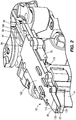
FIG. 2 is a perspective view of a nosepiece assembly of the powered fastener driver ofFIG. 1 . -
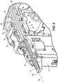
FIG. 3 is a perspective view of the nosepiece assembly of the powered fastener driver ofFIG. 1 , with a nosepiece removed. -
FIG. 4 is an enlarged perspective of the nosepiece assembly of the powered fastener driver ofFIG. 1 . -
FIG. 5A is a bottom perspective view of the nosepiece and a driver blade of the powered fastener driver ofFIG. 1 . -
FIG. 5B is a cross-sectional view of the nosepiece and driver blade ofFIG. 5A . -
FIG. 6A is a bottom perspective view of the nosepiece of the powered fastener driver ofFIG. 1 , illustrating a fastener in a fastener driving track. -
FIG. 6B is a reverse perspective view of the nosepiece and fastener ofFIG. 6B . -
FIG. 7 is a perspective view of the driver blade of the powered fastener driver ofFIG. 1 . -
FIG. 8 is a bottom perspective view of the nosepiece of the powered fastener driver ofFIG. 1 . -
FIG. 9 is a side view of the fastener driver ofFIG. 1 . -
FIG. 10 is a front view of the nosepiece assembly ofFIG. 2 , with portions removed. -
FIG. 11 is a bottom perspective view of the nosepiece and collated fasteners received in a fastener driving track of the nosepiece. -
FIG. 12 is plan view of the nosepiece and collated fasteners ofFIG. 11 . -
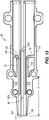
FIG. 13 is another plan view of the nosepiece and collated fasteners ofFIG. 11 . -
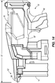
FIG. 14 is a side view of a powered fastener driver in accordance with another embodiment of the invention. -
FIG. 15A is a bottom perspective view of a nosepiece and a driver blade of the powered fastener driver ofFIG. 14 . -
FIG. 15B is a cross-sectional view of the nosepiece and driver blade of the powered fastener driver ofFIG. 14 . -
FIG. 16 is a perspective view of the driver blade of the powered fastener driverFIG. 14 . -
FIG. 17 is a bottom perspective view of the nosepiece of the powered fastener driver ofFIG 14 . -
FIG. 18 is a plan view the nosepiece and collated fasteners ofFIG. 14 . - Before any embodiments of the invention are explained in detail, it is to be understood that the invention is not limited in its application to the details of construction and the arrangement of components set forth in the following description or illustrated in the following drawings. The invention is capable of other embodiments and of being practiced or of being carried out in various ways. Also, it is to be understood that the phraseology and terminology used herein is for the purpose of description and should not be regarded as limiting.
- With reference to
FIG. 1 , a gas spring-poweredfastener driver 10 is operable to drive fasteners (e.g., nails, tacks, staples, etc.) held within amagazine 14 into a workpiece. Thefastener driver 10 includes acylinder 18. A moveable piston (not shown) is positioned within thecylinder 18. With reference toFIG. 2 , thefastener driver 10 further includes adriver blade 22 that is attached to the piston and moveable therewith. Thefastener driver 10 does not require an external source of air pressure, but rather includes pressurized gas in thecylinder 18. - With reference to
FIG. 1 , thefastener driver 10 includes ahousing 26 having acylinder housing portion 30 and amotor housing portion 34 extending therefrom. Thecylinder housing portion 30 is configured to support thecylinder 18, whereas themotor housing portion 34 is configured to support amotor 38 and atransmission 42 downstream of themotor 38. In addition, the illustratedhousing 26 includes ahandle portion 46 extending from thecylinder housing portion 30, and abattery attachment portion 50 coupled to an opposite end of thehandle portion 46. A battery (not shown) is electrically connectable to themotor 38 for supplying electrical power to themotor 38. Thehandle portion 46 supports a trigger (not shown), which is depressed by a user to initiate a driving cycle of thefastener driver 10. - With reference to
FIG. 3 , thedriver blade 22 defines alongitudinal axis 58. During a driving cycle, thedriver blade 22 and piston are moveable between a top-dead-center (TDC) or ready position within thecylinder 18, and a bottom-dead-center (BDC) or driven position, along theaxis 58. Thefastener driver 10 further includes a lifter assembly (not shown), which is powered by the motor 38 (FIG. 1 ), and which is operable to return thedriver blade 22 from the driven position to the ready position. - The
fastener driver 10 further includes anosepiece assembly 62 that receives collated fasteners from the magazine 14 (FIGS. 2 and4 ). Thenosepiece assembly 62 includes anosepiece 66 and ashear block 70 that collectively define a fastener driving channel or track 80 (FIGS. 6A, 6B , and8 ) that guides the fasteners as they are driven into a workpiece by thedriver blade 22. Theshear block 70 further defines an opening (not shown) that permits fasteners to pass from themagazine 14 through theshear block 70 and into thedriver track 80. - With reference to
FIGS. 5A, 5B , and7 , thedriver blade 22 includes anelongated body 74 having a first planar surface (i.e., a front surface 78) and an opposite, a second planar surface (i.e., a rear surface 82). Afirst edge 86 extends between thefront surface 78 and therear surface 82 along one lateral side of thebody 74, and asecond edge 90 extends between thefront surface 78 and therear surface 82 along an opposite lateral side of thebody 74. Thefront surface 78 is parallel to therear surface 82. Likewise, theedges - The
driver blade 22 includes a plurality oflift teeth 94 formed along thefirst edge 86 of thebody 74. Thefirst edge 86 extends in the direction of theaxis 58, and thelift teeth 94 project from thefirst edge 86 in a direction transverse to theaxis 58. Thelift teeth 94 are sequentially engaged with the lifter assembly during the return of thedriver blade 22 from the driven position to the ready position. In addition, thedriver blade 22 includes a plurality ofprojections 98 extending from the second edge in a direction transverse to theaxis 58. In one embodiment, the plurality ofprojections 98 are configured to engage a latch (not shown) of thefastener driver 10 for inhibiting thedriver blade 22 from moving toward the driven position. - The
driver blade 22 further includes afirst end 22a and a second end, ordistal end 22b opposite thefirst end 22a. The front andrear surfaces second edges second ends driver blade 22, thefirst end 22a includes anaperture 100 for receiving a fastener (e.g., screw, bolt, etc.) for connection with the piston. Thesecond end 22b of thedriver blade 22 is oriented perpendicular to theaxis 58 for striking fasteners fed from themagazine 14 and driving the fasteners into a workpiece. Thedriver blade 22 additionally includes anelongated recess 106 extending along the front surface 78 (i.e., the surface facing the nosepiece 66) of thedriver blade 22, the purpose of which is described below. - With reference to
FIG. 7 , thedriver blade 22 includes a guidingprojection 110 positioned on theelongated body 74. The guidingprojection 110 is parallel with thelongitudinal axis 58 of thedriver blade 22 and also extends in a direction that is transverse to theaxis 58 to be received within a corresponding recess 114 (FIGS. 4 ,6A ,6B , and8 ) within thenosepiece 66 to provide lateral stability to thedriver blade 22 as it reciprocates between its ready and driven positions. The guidingprojection 110 is located near thesecond end 22b of thedriver blade 22 and terminates before thedistal end 22b of thedriver blade 22, creating agap 112 between the guidingprojection 110 and thedistal end 22b (FIG. 7 ). This allows for thedriver blade 22 to be guided within thenosepiece 66, but also prevents theprojection 110 from contacting the work surface with thedriver blade 22. As such, the guidingprojection 110 does not cause a "mar" or "indentation" on the work surface as a fastener (i.e., staple 102) is driven into the surface. - The
nosepiece 66 includes anelongated body 118 having a first planar surface, orfront surface 122 and an opposite, second planar surface, orrear surface 126, such that thefront surface 122 is parallel to therear surface 126. Thenosepiece 66 further includes anelongated guide groove 130 within therear surface 126 extending parallel with theaxis 58 that partially defines the fastener driver track 80 (FIGS. 6A and 6B ). Theguide groove 130 is sized to receive the width of the driver blade 22 (below the last of theteeth 94 and projections 98) and thestaples 102 to provide lateral stability to thestaples 102 as they are driven from the nosepiece assembly 62 (FIG. 4 ). Therecess 114 in which the guidingprojection 110 is received is also located in theguide groove 130. - With reference to
FIGS. 6A, 6B , and8 , thenosepiece 66 includesguide ribs 134 extending along therear surface 126 of thenosepiece 66, such that theribs 134 are substantially parallel to each other. The space between theribs 94 defines an extension of theguide groove 130 and provides additional lateral support for thestaples 102 during a firing operation. Specifically, when in thefastener driver track 80, anupper portion 102a of thestaple 102 is supported by theguide ribs 134 and alower portion 102b of thestaple 102 is supported within theguide groove 130. Thenosepiece 66 additionally includes laterally extendingribs 138 connecting opposite sides of thenosepiece 66 with therespective ribs 134. The laterally extendingribs 138 are oriented perpendicular relative to theguide ribs 134. In alternative embodiments (FIGS. 14-18 ), the laterally extendingribs 138 may be omitted. - More specifically, and with reference to the illustrated embodiment of the
fastener driver 10 ofFIGS. 11-13 , thestaple 102 includes a length L1 of approximately 37.75 mm. Theguide ribs 134 include a length L2 of 13.25 mm and theguide groove 130 includes a length L3 of 31.20 mm. Furthermore, a distance D1 from a crown of the staple 102 to a distal end of theguide rib 134 is approximately 5.5 mm. When thestaple 102 is loaded from themagazine 14 into thefastener driving track 80, theguide ribs 134 support approximately 13.25 mm, or 35%, of the length of the staple 102 (coinciding with length L2). Additionally, theguide groove 130 supports approximately 21.00 mm, or 55%, of the length L1 of the staple 102 (coinciding with length L3). As such, in total, approximately 34.25 mm, or 90%, of the length L1 of thestaple 102 is supported by a combination of theguide ribs 134 and theguide groove 130, leaving the remaining 10% of the length L1 of the staple 102 unsupported and extending beyond the distal ends of the guide ribs 134 (coinciding with distance D1). -
FIGS. 14-18 illustrate an alternative embodiment of a fastener driver 10', with like parts as thefastener driver 10 ofFIGS. 1-13 being shown with like reference numerals plus a prime marker ('). - The fastener driver 10' includes a driver blade 22' that is attached to a piston and moveable therewith. The fastener driver 10' further includes a nosepiece assembly 62' including a nosepiece 66' and a shear block (not shown, similar to the
shear block 70 shown inFIGS. 2-3 ) that collectively define a fastener driving channel or track 80' (FIG. 17 ) that guides fasteners as they are driven into a workpiece by the driver blade 22'. - With reference to
FIG. 16 , the driver blade 22' includes an elongated recess 106' extending along a front surface 78' (i.e., the surface facing the nosepiece 66') of the driver blade 22'. The elongated recess 106' includes a portion 108' having a greater width than the rest of the recess 106', the purpose of which is described below. - With reference to
FIGS. 17-18 , the nosepiece 66' includes a guide groove 130' sized to receive the width of the driver blade 22' (below the last of teeth 94' and projections 98' of the driver blade 22') and staples 102' to provide lateral stability to the staples 102' as they are driven from the nosepiece assembly 62'. The nosepiece 66' additionally includes guide ribs 134' extending along a rear surface 126' of the nosepiece 66', such that the ribs 134' are substantially parallel to each other. The space between the ribs 94' defines an extension of the guide groove 130' and provides additional lateral support for the staples 102' during a firing operation. - More specifically, and with reference to the illustrated embodiment of the fastener driver 10' of
FIG. 18 , the staple 102' includes a length L1' of approximately 37.75 mm. The guide ribs 134' include a length L2' of 13.25 mm and the guide groove 130' includes a length L3' of 31.20 mm. Furthermore, a distance D1' from a crown of the staple 102' to a distal end of the guide rib 134' is approximately 5.5 mm. When the staple 102' is loaded into the fastener driving track 80', the guide ribs 134' support approximately 13.25 mm, or 35%, of the length of the staple 102'. Additionally, the guide groove 130' supports approximately 21.00 mm, or 55%, of the length L1' of the staple 102'. As such, in total, approximately 34.25 mm, or 90%, of the length L1' of the staple 102' is supported by a combination of the guide ribs 134' and the guide groove 130', leaving the remaining 10% of the length L1' of the staple 102' unsupported and extending beyond the distal ends of the guide ribs 134'. - As the driver blade 22' moves from the ready position to the driven position (with the driven position being shown in
FIGS. 15A and 15B ), the guide ribs 134' of the nosepiece 66' slide within the enlarged portion 108' of the elongated recess 106' in the driver blade 22' (FIGS. 15B and16 ). Because the driver blade 22' overlaps the guide ribs 134' in this manner, the overall height of the fastener driver 10' is reduced, compared to a prior art fastener driver in which the majority of the length of the fasteners is supported within the guide groove 130'. In some embodiments of the fastener driver 10', the ratio of a length L4' from the crown of the staple 102' to a distal end of the nosepiece 66' (FIG. 18 ) to a total length L5' of the tool 10' (FIG. 14 ) is less than 25%. In the illustrated embodiment of the fastener driver 10', the length L4' is 57.5 mm (FIG. 18 ), and the total length L5' of the tool 10' is 263.3 mm (FIG. 14 ). As such, the ratio of L4':L5' is approximately 22%. - Various feature of the invention are set forth in the following claims.
Claims (15)
- A fastener driver comprising:a housing;a cylinder disposed within the housing;a piston positioned and moveable within the cylinder;a nosepiece at least partially defining a fastener driving track through which fasteners are driven; anda driver blade attached to the piston and moveable with the piston to drive the fasteners through the fastener driving track;wherein the driver blade includes an axial guiding projection for guiding the driver blade within the nosepiece, and wherein the projection terminates before a distal end of the driver blade.
- The fastener driver of claim 1, wherein the axial guiding projection is oriented parallel with a longitudinal axis of the driver blade.
- The fastener driver of either one of claims 1 or 2, wherein the axial guiding projection extends from the driver blade in a direction transverse to the longitudinal axis.
- The fastener driver of any one of claims 1 to 3, wherein the nosepiece includes a recess extending along a length of the nosepiece, and wherein the recess is configured to receive the axial guiding projection,
and optionally, wherein the nosepiece includes a longitudinal guide groove in which the fasteners are received, and wherein the longitudinal guide groove at least partially defines the fastener driving track,and further optionally, wherein the nosepiece includes parallel guide ribs extending from an interior surface of the nosepiece, thereby defining an extension of the guide groove,and further optionally, wherein the recess in which the axial guiding projection of the driver blade is received extends is positioned within the longitudinal guide groove and between the parallel guide ribs,and/or optionally, wherein the fastener driving track is defined at least partially by the longitudinal guide groove and the parallel guide ribs. - The fastener driver of any preceding claim, wherein the driver blade includes an elongated recess extending along a surface of the driver blade facing the nosepiece.
- The fastener driver of claim 5, wherein the driver blade is movable from a first position toward a second position during a fastener driving operation, wherein in the first position of the driver blade, an upper portion of the fastener within the fastener driving track is received between the parallel guide ribs and a lower portion of the fastener is received in the guide groove, and wherein when the driver blade is in the second position, the parallel guide ribs are at least partially received within the elongated recess in the driver blade.
- The fastener driver of claim 6, wherein a ratio of a length from a crown of one of the fasteners to a distal end of the nosepiece to a total length of the fastener driver is less than 25%.
- The fastener driver of either one of claims 6 or 7, wherein when the driver blade is in the second position, the nosepiece supports approximately 90% of the length of the one of the fasteners.
- A fastener driver comprising:a housing;a cylinder disposed within the housing;a piston positioned and moveable within the cylinder;a driver blade attached to the piston and moveable with the piston from a first position toward a second position during a fastener driving operation; anda nosepiece at least partially defining a fastener driving track through which fasteners are driven by the driver blade, wherein the nosepiece includesa longitudinal guide groove in which a fastener is received, andparallel ribs extending from an interior surface of the nosepiece, thereby defining an extension of the guide groove;wherein when the driver blade is in the second position, the driver blade partially overlaps with the guide ribs, thereby allowing a first portion of the fastener to be received in the guide ribs and a lower, second portion of the fastener to be received in the guide groove.
- The fastener driver of claim 9, wherein the longitudinal guide groove at least partially defines the fastener driving track and is configured to receive a portion of the driver blade.
- The fastener driver of claim 9, wherein the driver blade includes an axial guiding projection for guiding the driver blade within the nosepiece,
and optionally, wherein the projection terminates before a distal end of the driver blade. - The fastener driver of claim 11, wherein the nosepiece includes a recess extending along a length of the nosepiece, and wherein the recess is configured to receive the axial guiding projection,
and optionally, wherein the recess in which the axial guiding projection of the driver blade is received extends is positioned within the longitudinal guide groove and between the parallel guide ribs. - The fastener driver of any one of claims 9 to 12,
wherein the fastener driving track is defined at least partially by the longitudinal guide groove and the parallel guide ribs,
and/or wherein the driver blade includes an elongated recess extending along a surface of the driver blade facing the nosepiece,
and optionally, wherein in the first position of the driver blade, an upper portion of the fastener within the fastener driving track is received between the parallel guide ribs and a lower portion of the fastener is received in the guide groove, and wherein when the driver blade is in the second position, the parallel guide ribs are at least partially received within the elongated recess in the driver blade,
and/or wherein the first portion of the fastener is approximately 35% of a length of the fastener, and the second portion of the fastener is approximately 55% of the length of the fastener,
and optionally, wherein when the driver blade is in the second position, a third portion of the fastener extends beyond a distal end of the parallel guide ribs,
and/or wherein a ratio of a length from a crown of one of the fasteners to a distal end of the nosepiece to a total length of the fastener driver is less than 25%,
and/or wherein when the driver blade is in the second position, the nosepiece supports approximately 90% of the length of the one of the fasteners. - A fastener driver comprising:a housing;a cylinder disposed within the housing;a piston positioned and moveable within the cylinder;a driver blade attached to the piston and moveable with the piston from a first position toward a second position during a fastener driving operation; anda nosepiece at least partially defining a fastener driving track through which fasteners are driven by the driver blade;wherein when the driver blade is in the second position, the driver blade partially overlaps with a portion of the nosepiece, and a ratio of a length from a crown of one of the fasteners to a distal end of the nosepiece to a total length of the fastener driver is less than 25%.
- The fastener driver of claim 14,
wherein when the driver blade is in the second position, the ratio of the length from the crown of one of the fasteners to the distal end of the nosepiece to the total length of the fastener driver is 22%,
and/or wherein when the driver blade is in the second position, the nosepiece supports approximately 90% of the length of the one of the fasteners,
and/or wherein the nosepiece includesa longitudinal guide groove in which a fastener is received, andparallel ribs extending from an interior surface of the nosepiece, thereby defining an extension of the guide groove in which the fastener is also at least partially received,and optionally, wherein the driver blade includes an elongated recess extending along a surface of the driver blade facing the nosepiece, wherein in the first position of the driver blade, an upper portion of the fastener within the fastener driving track is received between the parallel guide ribs and a lower portion of the fastener is received in the guide groove, and wherein when the driver blade is in the second position, the parallel guide ribs are at least partially received within the elongated recess in the driver blade.
Applications Claiming Priority (1)
| Application Number | Priority Date | Filing Date | Title |
|---|---|---|---|
| US201962799141P | 2019-01-31 | 2019-01-31 |
Publications (3)
| Publication Number | Publication Date |
|---|---|
| EP3689550A2 true EP3689550A2 (en) | 2020-08-05 |
| EP3689550A3 EP3689550A3 (en) | 2021-03-31 |
| EP3689550B1 EP3689550B1 (en) | 2024-10-16 |
Family
ID=69411272
Family Applications (1)
| Application Number | Title | Priority Date | Filing Date |
|---|---|---|---|
| EP20154512.6A Active EP3689550B1 (en) | 2019-01-31 | 2020-01-30 | Powered fastener driver |
Country Status (3)
| Country | Link |
|---|---|
| US (6) | US11130221B2 (en) |
| EP (1) | EP3689550B1 (en) |
| CN (1) | CN211967374U (en) |
Families Citing this family (7)
| Publication number | Priority date | Publication date | Assignee | Title |
|---|---|---|---|---|
| US11130221B2 (en) | 2019-01-31 | 2021-09-28 | Milwaukee Electric Tool Corporation | Powered fastener driver |
| JP7332522B2 (en) * | 2020-03-31 | 2023-08-23 | 株式会社マキタ | driving tool |
| CN217168397U (en) | 2021-12-07 | 2022-08-12 | 南京腾亚精工科技股份有限公司 | A dust-proof fastener hitting tool |
| US20250387891A1 (en) * | 2022-06-30 | 2025-12-25 | Koki Holdings Co., Ltd. | Working machine |
| US12420395B2 (en) * | 2022-08-15 | 2025-09-23 | Taizhou Dajiang Ind. Co. Ltd. | Nail passage and driving mechanisms and nail gun having same |
| JP2024103124A (en) * | 2023-01-20 | 2024-08-01 | 株式会社マキタ | Driving tools |
| CN223289743U (en) * | 2023-09-14 | 2025-09-02 | 米沃奇电动工具公司 | Power tool brake stop |
Family Cites Families (152)
| Publication number | Priority date | Publication date | Assignee | Title |
|---|---|---|---|---|
| US2769173A (en) | 1955-05-27 | 1956-11-06 | Bostitch Inc | Staple magazine and feed means for stapling machines |
| BE571634A (en) | 1958-04-10 | |||
| US3087162A (en) * | 1960-07-14 | 1963-04-30 | Phillip E Saurenman | Pneumatic gun for corrugated nails and the like |
| US3387541A (en) | 1965-02-24 | 1968-06-11 | Behrens Friedrich Joh | Pneumatic fastening machines for staples, nails, or the like fasteners |
| DE1628027B2 (en) | 1966-01-12 | 1971-03-11 | Wucherpfennig, Herbert, 3000 Han nover | Device for locking the magazine interest on a handheld device for driving in fasteners |
| DE1703921B1 (en) | 1968-07-31 | 1971-08-12 | Dieter Haubold Ind Nagelgeraet | Device for locking the magazine on a hand-held device for driving in fasteners |
| US3856139A (en) | 1969-10-27 | 1974-12-24 | Co Woodloc Inc | Carrier means for automatically driven fasteners |
| US3693863A (en) | 1969-10-27 | 1972-09-26 | Hugh Black | Tool attachment and method for automatically applying fasteners |
| US3734379A (en) | 1971-05-21 | 1973-05-22 | Powers Wire Products Co Inc | Air biased magazine lock and guideway closure for fastener driving tools |
| US3913817A (en) | 1973-02-01 | 1975-10-21 | Swingline Inc | Fastening element driving tool |
| US4305541A (en) * | 1979-10-01 | 1981-12-15 | Swingline Inc. | Electronically operated portable nail gun |
| US4747338A (en) * | 1983-06-13 | 1988-05-31 | Sencorp | Pneumatic gun having improved firing valve |
| EP0229195B1 (en) | 1985-12-14 | 1989-08-16 | Joh. Friedrich Behrens AG | Magazine for a power-driven tool for driving pins or nails or the like |
| JP2640988B2 (en) | 1990-11-30 | 1997-08-13 | 株式会社 マキタ | Prevention device for empty hitting of nails in nailing machine |
| DE4109362A1 (en) | 1991-03-22 | 1992-09-24 | Bosch Gmbh Robert | DRIVING DEVICE FOR STAPLES |
| US5181450A (en) | 1991-05-16 | 1993-01-26 | Umberto Monacelli | Pneumatic fastener driving apparatus with piston holding detent |
| US5207143A (en) | 1991-05-16 | 1993-05-04 | Umberto Monacelli | Pneumatic fastener driving apparatus with an improved valve |
| EP0584395A1 (en) | 1992-08-28 | 1994-03-02 | Umberto Monacelli | Pneumatic fastener driving apparatus with an improved piston |
| DE69227683T2 (en) | 1992-08-28 | 1999-04-22 | The Stanley Works C.V., New Britain, Conn. | Pneumatic fastener driving tool with improved valve |
| US5407118A (en) | 1993-06-10 | 1995-04-18 | Worktools, Inc. | Forward acting, staple machine with passive release |
| JPH07246575A (en) | 1994-03-11 | 1995-09-26 | Makita Corp | Nailer |
| JP3419535B2 (en) | 1994-03-11 | 2003-06-23 | 株式会社マキタ | Nailing machine |
| US5522533A (en) | 1994-03-18 | 1996-06-04 | Makita Corporation | Magazine for use with fastener driving tool |
| IT1279670B1 (en) | 1995-11-02 | 1997-12-16 | Fasco Spa | COMPRESSED AIR FIXING MACHINE WITH VALVE IN THE HEAD OPERATING WITH SINGLE SHOT AND REPEAT. |
| DE29600029U1 (en) | 1996-01-02 | 1996-12-12 | Hou, Chang Feng-Mei, Tai-Ping Hsiang, Taichung | Nail magazine for a powered nailer |
| JPH09300238A (en) | 1996-05-10 | 1997-11-25 | Hitachi Koki Co Ltd | Driver blade for a driving machine |
| JP3626011B2 (en) | 1998-05-11 | 2005-03-02 | 株式会社マキタ | Nailing machine |
| WO2000059687A1 (en) | 1999-04-05 | 2000-10-12 | Stanley Fastening Systems, L.P. | Safety trip assembly and trip lock mechanism for a fastener driving tool |
| US6648202B2 (en) | 2001-02-08 | 2003-11-18 | Black & Decker Inc. | Pneumatic fastening tool |
| US6609646B2 (en) | 2001-02-08 | 2003-08-26 | Black & Decker Inc. | Magazine assembly for fastening tool |
| US6679413B2 (en) | 2001-02-08 | 2004-01-20 | Black & Decker Inc. | Magazine assembly for fastening tool |
| US7025875B2 (en) | 2001-05-14 | 2006-04-11 | Delphi Technologies, Inc. | Diesel fuel reforming strategy |
| US20030121948A1 (en) | 2001-12-31 | 2003-07-03 | Hsien Chen Ming | Device for disabling shooting when nails runs out in a pneumatic nailer |
| US20030146262A1 (en) | 2002-02-07 | 2003-08-07 | Senco Products, Inc. | Fastener positioning apparatus for a fastener driving tool |
| US7025242B1 (en) | 2002-09-18 | 2006-04-11 | Black & Decker Inc. | Adjustable angle magazine |
| US6938809B1 (en) | 2002-09-18 | 2005-09-06 | Porter-Cable Corporation | Nail lockout assembly |
| US7143508B2 (en) | 2002-09-18 | 2006-12-05 | Black & Decker Inc. | Nail spacing verification assembly |
| US20060102683A1 (en) | 2002-09-18 | 2006-05-18 | Schnell John W | Adjustable angle magazine with pick-off pivot assembly |
| FR2846583B1 (en) | 2002-11-06 | 2005-01-14 | Prospection & Inventions | ASSEMBLY OF A BOILER AND A SEALING APPARATUS |
| DE20217134U1 (en) | 2002-11-06 | 2003-01-16 | Tsai, Chien-Fang, Tainan | Pneumatic nail machine comprises main body, nail guide block, tension block and nail magazine, guide block being fixed to main body |
| JP4348995B2 (en) | 2003-05-08 | 2009-10-21 | マックス株式会社 | Nail launch guide mechanism in nailing machine |
| US20050001007A1 (en) | 2003-05-29 | 2005-01-06 | Butzen Robert W. | Pneumatic nailer |
| US6966476B2 (en) | 2003-07-30 | 2005-11-22 | Stanley Fastening Systems, L.P. | Integrated check pawl, last nail-retaining, and dry fire lock-out mechanism for fastener-driving tool |
| DE10341387B4 (en) | 2003-09-05 | 2014-09-18 | Hilti Aktiengesellschaft | Anpressstift |
| US6986448B2 (en) | 2003-09-09 | 2006-01-17 | Illinois Tool Works Inc. | Fastener driving tool for spacing object from substrate |
| US6851594B1 (en) | 2003-10-17 | 2005-02-08 | Siu-Tsai Huang | Positioning staple case of stacker |
| US6837414B1 (en) | 2003-12-03 | 2005-01-04 | Kun-Chuan Chou | Magazine for a powered nail-driving tool |
| US7988025B2 (en) | 2004-02-24 | 2011-08-02 | Black & Decker Inc. | Pneumatic fastener |
| US7021516B2 (en) * | 2004-03-05 | 2006-04-04 | Illinois Tool Works Inc. | Driver blade for fastening tool |
| US7641089B2 (en) | 2004-04-02 | 2010-01-05 | Black & Decker Inc. | Magazine assembly for nailer |
| US7137541B2 (en) | 2004-04-02 | 2006-11-21 | Black & Decker Inc. | Fastening tool with mode selector switch |
| US8408327B2 (en) | 2004-04-02 | 2013-04-02 | Black & Decker Inc. | Method for operating a power driver |
| EP1584418B1 (en) | 2004-04-02 | 2008-05-07 | BLACK & DECKER INC. | Fastening tool with mode selector switch |
| US7285877B2 (en) | 2004-04-02 | 2007-10-23 | Black & Decker Inc. | Electronic fastening tool |
| JP4420205B2 (en) | 2004-04-28 | 2010-02-24 | マックス株式会社 | Nail guide device for nailing machine |
| US7971768B2 (en) | 2004-05-04 | 2011-07-05 | Illinois Tool Works Inc. | Guidance system for fasteners |
| US7134586B2 (en) | 2004-06-30 | 2006-11-14 | Stanley Fastening Systems, L.P. | Fastener driving device |
| JP4618537B2 (en) | 2004-07-15 | 2011-01-26 | 日立工機株式会社 | Nailer |
| WO2006026709A2 (en) | 2004-08-30 | 2006-03-09 | Black & Decker Inc. | Combustion fastener |
| US20060118594A1 (en) | 2004-12-03 | 2006-06-08 | Robert Chen | Nailing gun with improved nail magazine |
| DE102005016454A1 (en) | 2005-04-11 | 2006-10-12 | Robert Bosch Gmbh | Hand tool for driving in staples and / or nails |
| US20070075112A1 (en) | 2005-10-04 | 2007-04-05 | Porth Chris H | Nose assembly for a fastener driving tool |
| DE102005000149A1 (en) | 2005-11-04 | 2007-05-10 | Hilti Ag | Internal combustion setting device |
| JP2007160411A (en) | 2005-12-09 | 2007-06-28 | Makita Corp | Idle blow preventing device of driving machine |
| JP4984581B2 (en) | 2006-03-14 | 2012-07-25 | マックス株式会社 | How to attach / detach the contact top of the nailer |
| TWM312400U (en) | 2006-09-08 | 2007-05-21 | Samson Power Tool Co Ltd | Position-limiting adjustment structure for cartridge of nail gun |
| JP4984779B2 (en) | 2006-09-19 | 2012-07-25 | マックス株式会社 | Gas fired driving tool |
| US7753243B2 (en) | 2006-10-25 | 2010-07-13 | Black & Decker Inc. | Lock-out mechanism for a power tool |
| DE102006035370A1 (en) | 2006-10-27 | 2008-04-30 | Hilti Ag | Hand-operated tacker for driving e.g. nail, in workpiece, has pressing unit provided with spring unit, whose spring force is changeable to vector of gravitational force depending on spatial orientation of pressing unit |
| WO2008061004A2 (en) | 2006-11-09 | 2008-05-22 | Stanley Fastening Systems, L.P. | Cordless fastener driving device |
| DE102006035460A1 (en) | 2006-11-27 | 2008-05-29 | Hilti Ag | Hand-guided tacker |
| DE102006035459A1 (en) | 2006-11-27 | 2008-05-29 | Hilti Ag | Hand-guided tacker |
| JP4899840B2 (en) | 2006-12-05 | 2012-03-21 | マックス株式会社 | Gas fired driving tool |
| US7646157B2 (en) | 2007-03-16 | 2010-01-12 | Black & Decker Inc. | Driving tool and method for controlling same |
| JP5395333B2 (en) | 2007-05-11 | 2014-01-22 | 日立工機株式会社 | Driving machine |
| TW200909152A (en) | 2007-08-23 | 2009-03-01 | Basso Ind Corp | Nail cartridge capable of dual direction nail-filling |
| JP5067082B2 (en) | 2007-09-07 | 2012-11-07 | 日立工機株式会社 | Driving machine |
| US8123096B2 (en) | 2007-09-13 | 2012-02-28 | Hitachi Koki Co., Ltd. | Driving machine |
| JP5064958B2 (en) | 2007-10-04 | 2012-10-31 | 株式会社マキタ | Driving tool |
| EP2243600B1 (en) | 2007-10-05 | 2015-11-25 | Senco Brands, Inc | Fastener driving tool using a gas spring and method for controlling the tool |
| US8763874B2 (en) | 2007-10-05 | 2014-07-01 | Senco Brands, Inc. | Gas spring fastener driving tool with improved lifter and latch mechanisms |
| DE102008040131A1 (en) | 2008-07-03 | 2010-01-07 | Hilti Aktiengesellschaft | Hand-guided tacker |
| US7905377B2 (en) | 2008-08-14 | 2011-03-15 | Robert Bosch Gmbh | Flywheel driven nailer with safety mechanism |
| US8042717B2 (en) | 2009-04-13 | 2011-10-25 | Stanley Fastening Systems, Lp | Fastener driving device with contact trip having an electrical actuator |
| JP2011088269A (en) | 2009-09-25 | 2011-05-06 | Makita Corp | Driving tool |
| US8083116B2 (en) | 2009-10-14 | 2011-12-27 | De Poan Pneumatic Corp. | Braking and driving mechanism for nail gun |
| US8052021B2 (en) | 2010-01-13 | 2011-11-08 | De Poan Pneumatic Corp. | Braking mechanism for empty nail cartridge of nail gun |
| DE102010030119A1 (en) | 2010-06-15 | 2011-12-15 | Hilti Aktiengesellschaft | driving- |
| DE102010030055A1 (en) | 2010-06-15 | 2011-12-15 | Hilti Aktiengesellschaft | Electrically operated bolt gun and method for operating the bolt gun |
| DE102010030091A1 (en) | 2010-06-15 | 2011-12-15 | Hilti Aktiengesellschaft | driving- |
| US8833626B2 (en) | 2010-09-29 | 2014-09-16 | Stanley Fastening Systems, L.P. | Fastening tool |
| US8292143B2 (en) | 2010-10-12 | 2012-10-23 | Stanley Fastening Systems, L.P. | Dry fire lockout with bypass for fastener driving device |
| TWM403405U (en) | 2010-11-03 | 2011-05-11 | Basso Ind Corp | Control structure of electrical nailing gun |
| TWI401143B (en) | 2010-11-03 | 2013-07-11 | 鑽全實業股份有限公司 | Electric nail gun double switch device |
| TWM406500U (en) | 2011-01-24 | 2011-07-01 | De Poan Pneumatic Corp | Air nail locking device for pneumatic nail gun |
| US9463560B2 (en) | 2011-10-03 | 2016-10-11 | Illinois Tool Works Inc. | Portable pressurized power source for fastener driving tool |
| US9770818B2 (en) | 2011-10-03 | 2017-09-26 | Illinois Tool Works Inc. | Fastener driving tool with portable pressurized power source |
| JP2013111719A (en) | 2011-11-30 | 2013-06-10 | Makita Corp | Driving tool |
| US9827658B2 (en) | 2012-05-31 | 2017-11-28 | Black & Decker Inc. | Power tool having latched pusher assembly |
| US11229995B2 (en) | 2012-05-31 | 2022-01-25 | Black Decker Inc. | Fastening tool nail stop |
| US9643305B2 (en) | 2012-05-31 | 2017-05-09 | Black & Decker Inc. | Magazine assembly for fastening tool |
| US9498871B2 (en) | 2012-05-31 | 2016-11-22 | Black & Decker Inc. | Power tool raving spring curl trip actuator |
| US9486904B2 (en) | 2012-05-31 | 2016-11-08 | Black & Decker Inc. | Fastening tool nosepiece insert |
| US20130320063A1 (en) | 2012-05-31 | 2013-12-05 | Black & Decker, Inc. | Fastening tool nail feed funnel |
| US9649755B2 (en) | 2012-05-31 | 2017-05-16 | Black & Decker Inc. | Power tool having angled dry fire lockout |
| US9469021B2 (en) | 2012-05-31 | 2016-10-18 | Black & Decker Inc. | Fastening tool nail channel |
| US20140021237A1 (en) | 2012-07-20 | 2014-01-23 | Chin-Chin Chang | Spring biased lock for magazine of nail gun |
| US8733610B2 (en) | 2012-08-21 | 2014-05-27 | Tricord Solutions, Inc. | Fastener driving apparatus |
| DE102012215126A1 (en) | 2012-08-24 | 2014-05-28 | Hilti Aktiengesellschaft | Hand-held implement |
| JP5998847B2 (en) | 2012-10-25 | 2016-09-28 | マックス株式会社 | Nailer |
| JP2014091196A (en) | 2012-11-05 | 2014-05-19 | Makita Corp | Driving tool |
| JP5991425B2 (en) * | 2013-03-29 | 2016-09-14 | 日立工機株式会社 | Driving machine |
| US8939341B2 (en) | 2013-06-20 | 2015-01-27 | Tricord Solutions, Inc. | Fastener driving apparatus |
| US9555530B2 (en) | 2013-06-20 | 2017-01-31 | Tricord Solutions, Inc. | Fastener driving apparatus |
| EP2826601A1 (en) | 2013-07-16 | 2015-01-21 | HILTI Aktiengesellschaft | Control method and hand tool machine |
| EP2826600A1 (en) | 2013-07-16 | 2015-01-21 | HILTI Aktiengesellschaft | Control method and hand tool machine |
| EP2826599A1 (en) | 2013-07-16 | 2015-01-21 | HILTI Aktiengesellschaft | Control method and hand tool machine |
| US9796072B2 (en) | 2013-08-30 | 2017-10-24 | Illinois Tool Works Inc. | Staple tool |
| US9121427B2 (en) | 2013-08-30 | 2015-09-01 | Illinois Tool Works Inc. | Staple assembly |
| US10022848B2 (en) | 2014-07-28 | 2018-07-17 | Black & Decker Inc. | Power tool drive mechanism |
| US10434634B2 (en) | 2013-10-09 | 2019-10-08 | Black & Decker, Inc. | Nailer driver blade stop |
| US12502756B2 (en) | 2013-10-09 | 2025-12-23 | Black & Decker Inc. | High inertia driver system |
| US9527196B2 (en) | 2013-11-06 | 2016-12-27 | Illinois Tool Works Inc. | Fastener driving tool with an automatic nose chamber guide member |
| JP6284417B2 (en) | 2014-04-16 | 2018-02-28 | 株式会社マキタ | Driving tool |
| US10717179B2 (en) | 2014-07-28 | 2020-07-21 | Black & Decker Inc. | Sound damping for power tools |
| TW201615361A (en) | 2014-10-24 | 2016-05-01 | Jann Yei Industry Co Ltd | Nailer nail opening width adjustment mechanism |
| EP3037216A1 (en) | 2014-12-22 | 2016-06-29 | HILTI Aktiengesellschaft | Handheld tool and device comprising the handheld tool |
| US10322501B2 (en) | 2015-01-16 | 2019-06-18 | Black & Decker Inc. | Fastening tool having timed ready to fire mode |
| WO2016136632A1 (en) | 2015-02-26 | 2016-09-01 | 日立工機株式会社 | Driving machine |
| JP6408944B2 (en) | 2015-03-24 | 2018-10-17 | 株式会社マキタ | Driving tool |
| WO2016174994A1 (en) | 2015-04-30 | 2016-11-03 | 日立工機株式会社 | Driving machine |
| US10286533B2 (en) | 2015-05-08 | 2019-05-14 | Black & Decker Inc. | Depth adjustment mechanism for a fastening tool |
| CN208697341U (en) | 2015-05-27 | 2019-04-05 | 工机控股株式会社 | pile driver |
| WO2016199670A1 (en) | 2015-06-10 | 2016-12-15 | 日立工機株式会社 | Driving machine |
| JP6870208B2 (en) | 2016-03-11 | 2021-05-12 | マックス株式会社 | Driving tool |
| TWI558515B (en) | 2016-03-15 | 2016-11-21 | 堡勝企業股份有限公司 | Safety device for tackers |
| US10814465B2 (en) | 2016-03-22 | 2020-10-27 | Stanley Black & Decker, Inc. | Safety device for tackers |
| US11123850B2 (en) | 2016-06-30 | 2021-09-21 | Black & Decker Inc. | Cordless concrete nailer with removable lower contact trip |
| US11400572B2 (en) | 2016-06-30 | 2022-08-02 | Black & Decker, Inc. | Dry-fire bypass for a fastening tool |
| EP3269512B1 (en) * | 2016-07-12 | 2018-12-05 | Makita Corporation | Driving tool |
| US20180093370A1 (en) | 2016-10-04 | 2018-04-05 | Stanley Black & Decker, Inc. | Fastening Tool with Contact Arm and Multi-Fastener Guide |
| CA2981019A1 (en) * | 2016-10-10 | 2018-04-10 | Power Tech Staple and Nail, Inc. | Accessory attachment for driven fastener hand tool |
| CA3187695A1 (en) | 2016-11-09 | 2018-05-09 | Tti (Macao Commercial Offshore) Limited | Cylinder assembly for gas spring fastener driver |
| EP3321036B1 (en) | 2016-11-09 | 2021-02-24 | TTI (Macao Commercial Offshore) Limited | Jam release and lifter mechanism for gas spring fastener driver |
| CA2985234C (en) | 2016-11-09 | 2023-06-20 | Tti (Macao Commercial Offshore) Limited | Control system for gas spring fastener driver |
| WO2018100939A1 (en) | 2016-11-30 | 2018-06-07 | 日立工機株式会社 | Drive-in machine |
| US10821585B2 (en) * | 2016-12-22 | 2020-11-03 | Kyocera Senco Industrial Tools, Inc. | Fastener driving tool with driver position sensors |
| US10639776B2 (en) | 2016-12-22 | 2020-05-05 | Makita Corporation | Driving tool |
| US20180207779A1 (en) | 2017-01-20 | 2018-07-26 | Worktools, Inc. | Fastener magazine release system |
| EP3441190A1 (en) | 2017-08-07 | 2019-02-13 | HILTI Aktiengesellschaft | Driving device and method for use of a driving device |
| CN110450108A (en) * | 2018-05-08 | 2019-11-15 | 创科(澳门离岸商业服务)有限公司 | air tools |
| US11130221B2 (en) | 2019-01-31 | 2021-09-28 | Milwaukee Electric Tool Corporation | Powered fastener driver |
-
2020
- 2020-01-29 US US16/776,173 patent/US11130221B2/en active Active
- 2020-01-30 EP EP20154512.6A patent/EP3689550B1/en active Active
- 2020-02-03 CN CN202020150771.XU patent/CN211967374U/en active Active
-
2021
- 2021-08-26 US US17/412,486 patent/US11801591B2/en active Active
-
2022
- 2022-04-13 US US17/719,878 patent/US11931874B2/en active Active
-
2023
- 2023-09-11 US US18/464,922 patent/US12070841B2/en active Active
-
2024
- 2024-02-16 US US18/443,714 patent/US12569967B2/en active Active
-
2026
- 2026-03-06 US US19/558,729 patent/US20260192425A1/en active Pending
Also Published As
| Publication number | Publication date |
|---|---|
| US11931874B2 (en) | 2024-03-19 |
| US20210379747A1 (en) | 2021-12-09 |
| EP3689550A3 (en) | 2021-03-31 |
| US20200246949A1 (en) | 2020-08-06 |
| US12070841B2 (en) | 2024-08-27 |
| US11801591B2 (en) | 2023-10-31 |
| US20220241946A1 (en) | 2022-08-04 |
| US20240181615A1 (en) | 2024-06-06 |
| US12569967B2 (en) | 2026-03-10 |
| EP3689550B1 (en) | 2024-10-16 |
| CN211967374U (en) | 2020-11-20 |
| US20230415317A1 (en) | 2023-12-28 |
| US20260192425A1 (en) | 2026-07-09 |
| US11130221B2 (en) | 2021-09-28 |
Similar Documents
| Publication | Publication Date | Title |
|---|---|---|
| US12070841B2 (en) | Powered fastener driver | |
| US11260512B2 (en) | Powered fastener driver | |
| EP1951478B1 (en) | Combustion-powered driving tool with workpiece contact element | |
| EP1795305B1 (en) | Idle driving operation preventing devices for fastener driving tools, and fastener driving tools having such devices | |
| JP2011025362A (en) | Driving tool | |
| US20060231582A1 (en) | Stapler | |
| US12365072B2 (en) | Powered fastener driver | |
| WO2009101891A1 (en) | Nailer | |
| CN118372211A (en) | Insertion tool | |
| JP4569252B2 (en) | Power driven nailer | |
| EP4596176A1 (en) | Workpiece contact element for a powered fastener driver | |
| US7070081B2 (en) | Driver guides for use with fastener-driving tools and fastener-driving tools having such driver guides | |
| JP7761864B2 (en) | Work equipment | |
| EP1806208A1 (en) | Nailing device and magazine of nailing device | |
| CN219599403U (en) | Fastener driver and pusher assembly for fastener driver | |
| JP3952887B2 (en) | Contact member guide mechanism in nailing machine | |
| JPH0674277U (en) | Nailer nose | |
| JP5983084B2 (en) | Nailer | |
| JPH0615975U (en) | Nailing machine |
Legal Events
| Date | Code | Title | Description |
|---|---|---|---|
| PUAI | Public reference made under article 153(3) epc to a published international application that has entered the european phase |
Free format text: ORIGINAL CODE: 0009012 |
|
| STAA | Information on the status of an ep patent application or granted ep patent |
Free format text: STATUS: THE APPLICATION HAS BEEN PUBLISHED |
|
| AK | Designated contracting states |
Kind code of ref document: A2 Designated state(s): AL AT BE BG CH CY CZ DE DK EE ES FI FR GB GR HR HU IE IS IT LI LT LU LV MC MK MT NL NO PL PT RO RS SE SI SK SM TR |
|
| AX | Request for extension of the european patent |
Extension state: BA ME |
|
| PUAL | Search report despatched |
Free format text: ORIGINAL CODE: 0009013 |
|
| PUAF | Information related to the publication of a search report (a3 document) modified or deleted |
Free format text: ORIGINAL CODE: 0009199SEPU |
|
| AK | Designated contracting states |
Kind code of ref document: A3 Designated state(s): AL AT BE BG CH CY CZ DE DK EE ES FI FR GB GR HR HU IE IS IT LI LT LU LV MC MK MT NL NO PL PT RO RS SE SI SK SM TR |
|
| AX | Request for extension of the european patent |
Extension state: BA ME |
|
| RIC1 | Information provided on ipc code assigned before grant |
Ipc: B25C 1/06 20060101AFI20201104BHEP |
|
| D17D | Deferred search report published (deleted) | ||
| PUAL | Search report despatched |
Free format text: ORIGINAL CODE: 0009013 |
|
| AK | Designated contracting states |
Kind code of ref document: A3 Designated state(s): AL AT BE BG CH CY CZ DE DK EE ES FI FR GB GR HR HU IE IS IT LI LT LU LV MC MK MT NL NO PL PT RO RS SE SI SK SM TR |
|
| AX | Request for extension of the european patent |
Extension state: BA ME |
|
| RIC1 | Information provided on ipc code assigned before grant |
Ipc: B25C 1/06 20060101AFI20210223BHEP |
|
| STAA | Information on the status of an ep patent application or granted ep patent |
Free format text: STATUS: REQUEST FOR EXAMINATION WAS MADE |
|
| 17P | Request for examination filed |
Effective date: 20210706 |
|
| RBV | Designated contracting states (corrected) |
Designated state(s): AL AT BE BG CH CY CZ DE DK EE ES FI FR GB GR HR HU IE IS IT LI LT LU LV MC MK MT NL NO PL PT RO RS SE SI SK SM TR |
|
| STAA | Information on the status of an ep patent application or granted ep patent |
Free format text: STATUS: EXAMINATION IS IN PROGRESS |
|
| 17Q | First examination report despatched |
Effective date: 20230713 |
|
| GRAP | Despatch of communication of intention to grant a patent |
Free format text: ORIGINAL CODE: EPIDOSNIGR1 |
|
| STAA | Information on the status of an ep patent application or granted ep patent |
Free format text: STATUS: GRANT OF PATENT IS INTENDED |
|
| GRAJ | Information related to disapproval of communication of intention to grant by the applicant or resumption of examination proceedings by the epo deleted |
Free format text: ORIGINAL CODE: EPIDOSDIGR1 |
|
| STAA | Information on the status of an ep patent application or granted ep patent |
Free format text: STATUS: EXAMINATION IS IN PROGRESS |
|
| INTG | Intention to grant announced |
Effective date: 20240222 |
|
| GRAP | Despatch of communication of intention to grant a patent |
Free format text: ORIGINAL CODE: EPIDOSNIGR1 |
|
| STAA | Information on the status of an ep patent application or granted ep patent |
Free format text: STATUS: GRANT OF PATENT IS INTENDED |
|
| INTC | Intention to grant announced (deleted) | ||
| INTG | Intention to grant announced |
Effective date: 20240415 |
|
| GRAS | Grant fee paid |
Free format text: ORIGINAL CODE: EPIDOSNIGR3 |
|
| GRAA | (expected) grant |
Free format text: ORIGINAL CODE: 0009210 |
|
| STAA | Information on the status of an ep patent application or granted ep patent |
Free format text: STATUS: THE PATENT HAS BEEN GRANTED |
|
| AK | Designated contracting states |
Kind code of ref document: B1 Designated state(s): AL AT BE BG CH CY CZ DE DK EE ES FI FR GB GR HR HU IE IS IT LI LT LU LV MC MK MT NL NO PL PT RO RS SE SI SK SM TR |
|
| REG | Reference to a national code |
Ref country code: GB Ref legal event code: FG4D |
|
| REG | Reference to a national code |
Ref country code: CH Ref legal event code: EP |
|
| REG | Reference to a national code |
Ref country code: IE Ref legal event code: FG4D |
|
| REG | Reference to a national code |
Ref country code: DE Ref legal event code: R096 Ref document number: 602020039403 Country of ref document: DE |
|
| REG | Reference to a national code |
Ref country code: LT Ref legal event code: MG9D |
|
| REG | Reference to a national code |
Ref country code: NL Ref legal event code: MP Effective date: 20241016 |
|
| REG | Reference to a national code |
Ref country code: AT Ref legal event code: MK05 Ref document number: 1732576 Country of ref document: AT Kind code of ref document: T Effective date: 20241016 |
|
| PG25 | Lapsed in a contracting state [announced via postgrant information from national office to epo] |
Ref country code: NL Free format text: LAPSE BECAUSE OF FAILURE TO SUBMIT A TRANSLATION OF THE DESCRIPTION OR TO PAY THE FEE WITHIN THE PRESCRIBED TIME-LIMIT Effective date: 20241016 |
|
| PG25 | Lapsed in a contracting state [announced via postgrant information from national office to epo] |
Ref country code: NL Free format text: LAPSE BECAUSE OF FAILURE TO SUBMIT A TRANSLATION OF THE DESCRIPTION OR TO PAY THE FEE WITHIN THE PRESCRIBED TIME-LIMIT Effective date: 20241016 |
|
| PG25 | Lapsed in a contracting state [announced via postgrant information from national office to epo] |
Ref country code: IS Free format text: LAPSE BECAUSE OF FAILURE TO SUBMIT A TRANSLATION OF THE DESCRIPTION OR TO PAY THE FEE WITHIN THE PRESCRIBED TIME-LIMIT Effective date: 20250216 Ref country code: HR Free format text: LAPSE BECAUSE OF FAILURE TO SUBMIT A TRANSLATION OF THE DESCRIPTION OR TO PAY THE FEE WITHIN THE PRESCRIBED TIME-LIMIT Effective date: 20241016 Ref country code: PT Free format text: LAPSE BECAUSE OF FAILURE TO SUBMIT A TRANSLATION OF THE DESCRIPTION OR TO PAY THE FEE WITHIN THE PRESCRIBED TIME-LIMIT Effective date: 20250217 |
|
| PG25 | Lapsed in a contracting state [announced via postgrant information from national office to epo] |
Ref country code: FI Free format text: LAPSE BECAUSE OF FAILURE TO SUBMIT A TRANSLATION OF THE DESCRIPTION OR TO PAY THE FEE WITHIN THE PRESCRIBED TIME-LIMIT Effective date: 20241016 |
|
| PG25 | Lapsed in a contracting state [announced via postgrant information from national office to epo] |
Ref country code: BG Free format text: LAPSE BECAUSE OF FAILURE TO SUBMIT A TRANSLATION OF THE DESCRIPTION OR TO PAY THE FEE WITHIN THE PRESCRIBED TIME-LIMIT Effective date: 20241016 |
|
| PG25 | Lapsed in a contracting state [announced via postgrant information from national office to epo] |
Ref country code: ES Free format text: LAPSE BECAUSE OF FAILURE TO SUBMIT A TRANSLATION OF THE DESCRIPTION OR TO PAY THE FEE WITHIN THE PRESCRIBED TIME-LIMIT Effective date: 20241016 |
|
| PG25 | Lapsed in a contracting state [announced via postgrant information from national office to epo] |
Ref country code: NO Free format text: LAPSE BECAUSE OF FAILURE TO SUBMIT A TRANSLATION OF THE DESCRIPTION OR TO PAY THE FEE WITHIN THE PRESCRIBED TIME-LIMIT Effective date: 20250116 |
|
| PG25 | Lapsed in a contracting state [announced via postgrant information from national office to epo] |
Ref country code: LV Free format text: LAPSE BECAUSE OF FAILURE TO SUBMIT A TRANSLATION OF THE DESCRIPTION OR TO PAY THE FEE WITHIN THE PRESCRIBED TIME-LIMIT Effective date: 20241016 Ref country code: AT Free format text: LAPSE BECAUSE OF FAILURE TO SUBMIT A TRANSLATION OF THE DESCRIPTION OR TO PAY THE FEE WITHIN THE PRESCRIBED TIME-LIMIT Effective date: 20241016 Ref country code: GR Free format text: LAPSE BECAUSE OF FAILURE TO SUBMIT A TRANSLATION OF THE DESCRIPTION OR TO PAY THE FEE WITHIN THE PRESCRIBED TIME-LIMIT Effective date: 20250117 |
|
| PG25 | Lapsed in a contracting state [announced via postgrant information from national office to epo] |
Ref country code: PL Free format text: LAPSE BECAUSE OF FAILURE TO SUBMIT A TRANSLATION OF THE DESCRIPTION OR TO PAY THE FEE WITHIN THE PRESCRIBED TIME-LIMIT Effective date: 20241016 |
|
| PG25 | Lapsed in a contracting state [announced via postgrant information from national office to epo] |
Ref country code: RS Free format text: LAPSE BECAUSE OF FAILURE TO SUBMIT A TRANSLATION OF THE DESCRIPTION OR TO PAY THE FEE WITHIN THE PRESCRIBED TIME-LIMIT Effective date: 20250116 |
|
| PG25 | Lapsed in a contracting state [announced via postgrant information from national office to epo] |
Ref country code: SM Free format text: LAPSE BECAUSE OF FAILURE TO SUBMIT A TRANSLATION OF THE DESCRIPTION OR TO PAY THE FEE WITHIN THE PRESCRIBED TIME-LIMIT Effective date: 20241016 |
|
| PG25 | Lapsed in a contracting state [announced via postgrant information from national office to epo] |
Ref country code: DK Free format text: LAPSE BECAUSE OF FAILURE TO SUBMIT A TRANSLATION OF THE DESCRIPTION OR TO PAY THE FEE WITHIN THE PRESCRIBED TIME-LIMIT Effective date: 20241016 |
|
| REG | Reference to a national code |
Ref country code: DE Ref legal event code: R097 Ref document number: 602020039403 Country of ref document: DE |
|
| PG25 | Lapsed in a contracting state [announced via postgrant information from national office to epo] |
Ref country code: EE Free format text: LAPSE BECAUSE OF FAILURE TO SUBMIT A TRANSLATION OF THE DESCRIPTION OR TO PAY THE FEE WITHIN THE PRESCRIBED TIME-LIMIT Effective date: 20241016 |
|
| PG25 | Lapsed in a contracting state [announced via postgrant information from national office to epo] |
Ref country code: RO Free format text: LAPSE BECAUSE OF FAILURE TO SUBMIT A TRANSLATION OF THE DESCRIPTION OR TO PAY THE FEE WITHIN THE PRESCRIBED TIME-LIMIT Effective date: 20241016 |
|
| PG25 | Lapsed in a contracting state [announced via postgrant information from national office to epo] |
Ref country code: SK Free format text: LAPSE BECAUSE OF FAILURE TO SUBMIT A TRANSLATION OF THE DESCRIPTION OR TO PAY THE FEE WITHIN THE PRESCRIBED TIME-LIMIT Effective date: 20241016 |
|
| PG25 | Lapsed in a contracting state [announced via postgrant information from national office to epo] |
Ref country code: CZ Free format text: LAPSE BECAUSE OF FAILURE TO SUBMIT A TRANSLATION OF THE DESCRIPTION OR TO PAY THE FEE WITHIN THE PRESCRIBED TIME-LIMIT Effective date: 20241016 |
|
| PG25 | Lapsed in a contracting state [announced via postgrant information from national office to epo] |
Ref country code: IT Free format text: LAPSE BECAUSE OF FAILURE TO SUBMIT A TRANSLATION OF THE DESCRIPTION OR TO PAY THE FEE WITHIN THE PRESCRIBED TIME-LIMIT Effective date: 20241016 |
|
| PLBE | No opposition filed within time limit |
Free format text: ORIGINAL CODE: 0009261 |
|
| STAA | Information on the status of an ep patent application or granted ep patent |
Free format text: STATUS: NO OPPOSITION FILED WITHIN TIME LIMIT |
|
| REG | Reference to a national code |
Ref country code: CH Ref legal event code: PL |
|
| PG25 | Lapsed in a contracting state [announced via postgrant information from national office to epo] |
Ref country code: SE Free format text: LAPSE BECAUSE OF FAILURE TO SUBMIT A TRANSLATION OF THE DESCRIPTION OR TO PAY THE FEE WITHIN THE PRESCRIBED TIME-LIMIT Effective date: 20241016 |
|
| PG25 | Lapsed in a contracting state [announced via postgrant information from national office to epo] |
Ref country code: MC Free format text: LAPSE BECAUSE OF FAILURE TO SUBMIT A TRANSLATION OF THE DESCRIPTION OR TO PAY THE FEE WITHIN THE PRESCRIBED TIME-LIMIT Effective date: 20241016 Ref country code: LU Free format text: LAPSE BECAUSE OF NON-PAYMENT OF DUE FEES Effective date: 20250130 |
|
| 26N | No opposition filed |
Effective date: 20250717 |
|
| PG25 | Lapsed in a contracting state [announced via postgrant information from national office to epo] |
Ref country code: BE Free format text: LAPSE BECAUSE OF NON-PAYMENT OF DUE FEES Effective date: 20250131 |
|
| PG25 | Lapsed in a contracting state [announced via postgrant information from national office to epo] |
Ref country code: FR Free format text: LAPSE BECAUSE OF NON-PAYMENT OF DUE FEES Effective date: 20250131 |
|
| PG25 | Lapsed in a contracting state [announced via postgrant information from national office to epo] |
Ref country code: CH Free format text: LAPSE BECAUSE OF NON-PAYMENT OF DUE FEES Effective date: 20250131 |
|
| REG | Reference to a national code |
Ref country code: BE Ref legal event code: MM Effective date: 20250131 |
|
| PG25 | Lapsed in a contracting state [announced via postgrant information from national office to epo] |
Ref country code: IE Free format text: LAPSE BECAUSE OF NON-PAYMENT OF DUE FEES Effective date: 20250130 |
|
| PGFP | Annual fee paid to national office [announced via postgrant information from national office to epo] |
Ref country code: GB Payment date: 20260127 Year of fee payment: 7 |
|
| PGFP | Annual fee paid to national office [announced via postgrant information from national office to epo] |
Ref country code: DE Payment date: 20260128 Year of fee payment: 7 |
|
| PG25 | Lapsed in a contracting state [announced via postgrant information from national office to epo] |
Ref country code: CY Free format text: LAPSE BECAUSE OF FAILURE TO SUBMIT A TRANSLATION OF THE DESCRIPTION OR TO PAY THE FEE WITHIN THE PRESCRIBED TIME-LIMIT Effective date: 20241016 |
|
| PG25 | Lapsed in a contracting state [announced via postgrant information from national office to epo] |
Ref country code: TR Free format text: LAPSE BECAUSE OF FAILURE TO SUBMIT A TRANSLATION OF THE DESCRIPTION OR TO PAY THE FEE WITHIN THE PRESCRIBED TIME-LIMIT Effective date: 20241016 |
|
| PG25 | Lapsed in a contracting state [announced via postgrant information from national office to epo] |
Ref country code: LT Free format text: LAPSE BECAUSE OF FAILURE TO SUBMIT A TRANSLATION OF THE DESCRIPTION OR TO PAY THE FEE WITHIN THE PRESCRIBED TIME-LIMIT Effective date: 20241016 |