EP3689179A1 - Haarbehandlungsverfahren und haarhalter - Google Patents
Haarbehandlungsverfahren und haarhalter Download PDFInfo
- Publication number
- EP3689179A1 EP3689179A1 EP19154958.3A EP19154958A EP3689179A1 EP 3689179 A1 EP3689179 A1 EP 3689179A1 EP 19154958 A EP19154958 A EP 19154958A EP 3689179 A1 EP3689179 A1 EP 3689179A1
- Authority
- EP
- European Patent Office
- Prior art keywords
- hair
- tubular body
- diameter portion
- lock
- large diameter
- Prior art date
- Legal status (The legal status is an assumption and is not a legal conclusion. Google has not performed a legal analysis and makes no representation as to the accuracy of the status listed.)
- Granted
Links
Images


Classifications
-
- A—HUMAN NECESSITIES
- A45—HAND OR TRAVELLING ARTICLES
- A45D—HAIRDRESSING OR SHAVING EQUIPMENT; EQUIPMENT FOR COSMETICS OR COSMETIC TREATMENTS, e.g. FOR MANICURING OR PEDICURING
- A45D7/00—Processes of waving, straightening or curling hair
-
- A—HUMAN NECESSITIES
- A45—HAND OR TRAVELLING ARTICLES
- A45D—HAIRDRESSING OR SHAVING EQUIPMENT; EQUIPMENT FOR COSMETICS OR COSMETIC TREATMENTS, e.g. FOR MANICURING OR PEDICURING
- A45D2/00—Hair-curling or hair-waving appliances ; Appliances for hair dressing treatment not otherwise provided for
- A45D2/12—Hair winders or hair curlers for use parallel to the scalp, i.e. flat-curlers
- A45D2/14—Hair winders or hair curlers for use parallel to the scalp, i.e. flat-curlers of single-piece type, e.g. stiff rods or tubes with or without cord, band, or the like as hair-fastening means
- A45D2/146—Hair winders or hair curlers for use parallel to the scalp, i.e. flat-curlers of single-piece type, e.g. stiff rods or tubes with or without cord, band, or the like as hair-fastening means tube-like
-
- A—HUMAN NECESSITIES
- A45—HAND OR TRAVELLING ARTICLES
- A45D—HAIRDRESSING OR SHAVING EQUIPMENT; EQUIPMENT FOR COSMETICS OR COSMETIC TREATMENTS, e.g. FOR MANICURING OR PEDICURING
- A45D2/00—Hair-curling or hair-waving appliances ; Appliances for hair dressing treatment not otherwise provided for
- A45D2/02—Hair winders or hair curlers for use substantially perpendicular to the scalp, i.e. steep-curlers
- A45D2/08—Hair winders or hair curlers for use substantially perpendicular to the scalp, i.e. steep-curlers of hollow type
-
- A—HUMAN NECESSITIES
- A45—HAND OR TRAVELLING ARTICLES
- A45D—HAIRDRESSING OR SHAVING EQUIPMENT; EQUIPMENT FOR COSMETICS OR COSMETIC TREATMENTS, e.g. FOR MANICURING OR PEDICURING
- A45D2/00—Hair-curling or hair-waving appliances ; Appliances for hair dressing treatment not otherwise provided for
- A45D2002/003—Appliances for hair dressing treatment not otherwise provided for
- A45D2002/006—Appliances for hair dressing treatment not otherwise provided for for twisting hair
Definitions
- the present invention relates to a hair treatment method and a hair holder.
- Patent Literature 1 discloses a method in which a lock of hair is inserted into a pocket portion of a hair holder including a tubular body and the hair holder is then rolled up.
- Patent Literature 2 discloses a method for imparting a predetermined shape to a lock of hair by inserting a lock of hair into a tubular body of a hair holder, then winding the tubular body, and twisting, or folding like an accordion, the tubular body partially or entirely.
- the present invention provides a hair treatment method for curling a lock of hair using a hair holder including a tubular body, the tubular body having: a first opening located at a first end of the tubular body; and a second opening located at a second end of the tubular body, and being configured to allow a lock of hair to be inserted from the first opening toward the second opening and to be capable of being rolled up.
- the method includes: inserting a lock of hair into the hair holder, rolling up the tubular body together with a lock of hair inserted in the tubular body in such a manner that, in the tubular body, a large diameter portion that has a tubular shape and that forms an outer circumferential portion and a small diameter portion that is located inside the large diameter portion and has been formed thereby creating a space between the small diameter portion and the large diameter portion; and performing the curling while maintaining this wound state.
- the present invention provides hair holder including a tubular body which has: a first opening located at a first end of the tubular body; and a second opening located at a second end of the tubular body, and which is configured to allow a lock of hair to be inserted from the first opening toward the second opening and to be capable of being rolled up.
- the tubular body in its natural state is rolled up in such a manner that a large diameter portion that has a tubular shape and that forms an outer circumferential portion and a small diameter portion that is located inside the large diameter portion and that has a space between the small diameter portion and the large diameter portion are formed.
- a hairstyle in which a portion near hair ends is curly and portions other than the portion near the hair ends are straight.
- Such a hairstyle can be set by imparting two types of curl shapes with different roll diameters to a lock of hair.
- different tools are used for different roll diameters, and it is necessary to perform a curling treatment step for each roll diameter.
- the methods disclosed in Patent Documents 1 and 2 are the methods that impart a curl shape with a single roll diameter to hair and cannot address the above-described problems.
- the present invention relates to a hair treatment method and a hair holder with which the above-described drawbacks of the related art can be eliminated.
- the hair treatment method of the present invention is a hair treatment method for curling a lock of hair using a hair holder.
- “Curling” refers to imparting a particular shape to a lock of hair.
- the hair treatment method of the present invention is mainly applied to head hair.
- FIGS. 1A and 1B show an embodiment of the hair holder that is used in the hair treatment method of the present invention.
- a hair holder 1 shown in FIGS. 1A and 1B includes a tubular body 2 which has an opening 21 located at a first end and an opening 22 located at a second end.
- the tubular body 2 is configured to allow a lock of hair H be inserted from the opening 21 at a first end toward the opening 22 at a second end.
- the tubular body 2 has a flat shape formed by two sheets 23A and 23B that are elongated in one direction being laid one on top of the other, the two sheets 23A and 23B serving as a first surface sheet 23A and a second surface sheet 23B, which will be described later.
- the tubular body 2 also has a pair of side joint portions 24 where the first surface sheet 23A and the second surface sheet 23B are joined to each other, and a tubular portion 26 that is located between the pair of side joint portions 24.
- Each of the pair of side joint portions 24 are formed by joining side edge portions of the two sheets 23A and 23B to each other, the side edge portions extending along the extending direction of the two sheets.
- the tubular portion 26 has, between the opening 21 at the first end and the opening 22 at the second end, a space into which the lock of hair H can be inserted.
- the side joint portions 24 are formed through sewing using a sewing thread.
- the tubular body 2 of the present embodiment has a longitudinal direction X and a width direction Y that is orthogonal to the longitudinal direction X.
- the longitudinal direction X of the tubular body 2 is the same as the extending direction of the tubular portion 26 and corresponds to the direction in which the lock of hair H is inserted.
- Opposite side edge portions of the tubular body 2 that extend along the longitudinal direction X are parallel to each other as shown in the present embodiment; however, the opposite side edge portions need not be parallel to each other. In that case, it is preferable that the opposite side edge portions extend gradually outward in the width direction Y from the opening 21 at the first end toward the opening 22 at the second end. In other words, it is preferable that, in a plan view, the tubular body 2 has a shape that widens toward the opening 22 at the second end.
- the tubular body 2 is configured to be capable of being rolled up. Being configured to be capable of being rolled up means that the tubular body 2 can be wound into a roll shape. Such a configuration is preferably a configuration in which the tubular body 2 automatically rolls up, but may also be a configuration in which the tubular body 2 is manually rolled up.
- An example of the automatic rolling-up configuration is a configuration in which the tubular body 2 is wound in a roll shape in its natural state, and after stretching out the tubular body 2 and inserting a lock of hair H therein, the tubular body 2 rolls up together with the lock of hair H upon being released from the stretched state.
- Such a configuration can be realized by either or both of the two sheets 23A and 23B, which constitute the tubular body 2, being made of a shape memory sheet that has preliminarily retained the state in which the hair holder 1 is rolled up.
- the shape memory sheet can be formed by bonding together films having different heat shrinkage rates or films having different tensions, or by using a sheet containing a shape memory resin as a material for forming the shape memory sheet.
- the tubular body in a wound state is heated to a temperature equal to or higher than the glass transition temperature of the shape memory resin and then cooled, and in this manner, the tubular body can retain the wound state.
- tubular body 2 may also return to its retained original roll shape when the sheets 23A and 23B constituting the tubular body 2 are heated.
- “In its natural state” as used herein means the state that the hair holder where no eternal force is applied is horizontally placed in the environment of temperature of 20°C and humidity of 40%.
- the sheet that is located on the inside when rolled up is also referred to as the first surface sheet 23A, and the sheet that is located on the outside when rolled up is also referred to as the second surface sheet 23B.
- the tubular body 2 is rolled up together with the lock of hair H inserted in the tubular body 2 in such a manner that a large diameter portion 31 and a small diameter portion 33, which will be described later, are formed.
- the tubular body 2 that has been rolled up into a roll shape in such a manner that the large diameter portion 31 and the small diameter portion 33 are formed as shown in FIG. 2A will also be referred to as a lock-of-hair holding body. As shown in FIG.
- a lock-of-hair holding body 3 of the present embodiment has a spiral cross-sectional shape in a radial direction that is orthogonal to the direction of the central axis of the roll.
- the opening 22 at the second end is located on the center side of the roll that has been rolled up.
- the center is on the central axis of the lock-of-hair holding body that is roll-shaped.
- the tubular body 2 is rolled up together with a lock of hair to form the roll-shaped, lock-of-hair holding body 3 in this manner.
- the lock-of-hair holding body 3 has the large diameter portion 31 that has a tubular shape and forms an outer circumferential portion and the small diameter portion 33 that is located inside the large diameter portion 31 and has a space S between the smaller diameter portion and the large diameter portion.
- the wording "has a space S" means that the maximum distance between the large diameter portion 31 and the small diameter portion 33 in a cross section of the lock-of-hair holding body taken along the aforementioned radial direction is 5 mm or greater.
- the large diameter portion 31 is a wound portion that is the farthest from the central axis of the roll of the lock-of-hair holding body 3, and has the greatest roll diameter.
- the hair holder 1 has an extended portion, which will be described later, the extended portion is contained in the large diameter portion 31.
- the small diameter portion 33 is a wound portion that is nearer to the central axis than the large diameter portion 31.
- the outer diameter D2 of the small diameter portion 33 is smaller than the inner diameter D1 of the large diameter portion 31.
- the number of turns of the large diameter portion 31 is one.
- the number of turns of the small diameter portion 33 is less than one, or one or more, and may be two or more, for example.
- the number of turns of the small diameter portion 33 of the present embodiment is two, as shown in FIG. 2A .
- the tubular body is rolled up so as to form the above-described lock-of-hair holding body 3, and curling of the lock of hair is performed while maintaining this wound state.
- a preferred embodiment of the hair treatment method of the present invention will be described taking a case where the hair treatment method is performed using the hair holder 1 shown in FIGS. 1A and 1B as an example.
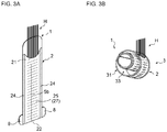
- FIGS. 3A and 3B illustrate a procedure of the hair treatment method of the present embodiment.
- the hair treatment method of the present embodiment includes a step of inserting a lock of hair H into the tubular body 2, a step of forming the lock-of-hair holding body 3, and a step of performing a curling treatment of the lock of hair H.
- the step of inserting a lock of hair H into the tubular body 2 will also be referred to as an insertion step, the step of forming the lock-of-hair holding body 3 as a rolling-up step, and the step of performing the curling treatment of the lock of hair as a curling treatment step.
- a lock of hair H is inserted into the tubular body 2 from the opening 21 at the first end of the tubular body 2 toward the opening 22 at the second end.
- the lock of hair H is inserted between the two sheets 23A and 23B constituting the tubular body 2.
- the base side of the lock of hair H is located on the opening 21 side at the first end
- the hair-end side is located on the opening 22 side at the second end.
- a hair-end portion near the hair ends of the lock of hair H inserted into the tubular body 2 is placed within the tubular body 2.
- a portion of the lock of hair H may protrude from the opening 22 at the second end.
- the operation of inserting the lock of hair H at the insertion step may be performed using an operator's hands, or may be performed using an elongated hair insertion tool for inserting a lock of hair H into the tubular body 2.
- An example of the hair insertion tool is a hair insertion tool having a locking portion that can lock the lock of hair H and an elongated, insertion tool main body that has a predetermined length. More specifically, in the hair insertion tool, the insertion tool main body is formed into an elongated plate-like shape, and an end portion thereof has a tapered shape so as to be easily inserted into the opening at the first end of the tubular body 2.
- the insertion tool main body is formed of a hard synthetic resin sheet or the like.
- the locking portion is provided at one end of the insertion tool main body, formed into a ring shape that is longer than it is wide, and the lock of hair can be inserted into, and locked in, this ring.
- the tubular body 2 is rolled up together with the lock of hair H inserted into the tubular body 2 to form the above-described lock-of-hair holding body 3.
- the tubular body 2 is rolled up from the opening 22 at the second end toward the opening 21 at the first end along the longitudinal direction X. That is to say, the tubular body 2 is rolled up in such a manner that the opening 22 at the second end is positioned on the center side of the lock-of-hair holding body that is roll-shaped, and thus the lock-of-hair holding body 3 is formed.
- the rolling-up of the tubular body 2 may be performed using the aforementioned configuration in which the tubular body 2 automatically rolls up, or may be performed using the aforementioned configuration in which the tubular body 2 is manually rolled up.
- the lock-of-hair holding body 3, that is, the large diameter portion 31 and the small diameter portion 33 may be formed at the same time as the tubular body 2 is rolled up. From the standpoint of making it easy to adjust the size of the large diameter portion 31 and the small diameter portion 33, it is preferable that, after the tubular body 2 has been rolled up into a semi-wound state, the large diameter portion 31 and the small diameter portion 33 are formed by performing a winding and tightening operation or an unwinding operation on a portion of the tubular body 2.
- the "semi-wound state” as used herein means a wound state prior to the formation of the large diameter portion 31 and the small diameter portion 33 and in which a space is not yet formed between the outer circumferential portion and a wound portion that is located nearer to the central axis than the outer circumferential portion.
- the lock of hair H inserted in the tubular body 2 is in a wound state similar to that of the lock-of-hair holding body 3, with the base side of the lock of hair H being placed in the large diameter portion 31, and the hair-end side in the small diameter portion 33.
- the portion of the lock of hair H that is placed in the large diameter portion 31 and the portion that is placed in the small diameter portion 33 have different roll diameters.
- the number of turns of the small diameter portion 33 corresponds to the number of turns of the portion of the lock of hair H that is placed in the small diameter portion 33. For example, if the number of turns of the small diameter portion 33 is two, the number of turns of the portion of the lock of hair H that is placed in the small diameter portion 33 is also two.
- the curling treatment step the curling treatment of the lock of hair H is performed while maintaining the wound state of the lock-of-hair holding body 3.
- the lock of hair H is maintained in a wound state similar to that of the lock-of-hair holding body by maintaining the form of the lock-of-hair holding body 3.
- the tubular body can be maintained in the form of the lock-of-hair holding body 3 using the configuration in which the tubular body automatically rolls up or a fixing means that fixes the tubular body in the wound state.
- the tubular body 2 can be maintained in the form of the lock-of-hair holding body 3 by using a hair clip 9 as the fixing means.
- the fixing means will be described later.
- the portion of the lock of hair H that is placed in the large diameter portion 31 is in a wound state similar to that of the large diameter portion 31.
- the portion of the lock of hair H that is placed in the small diameter portion 33 is in a wound state similar to that of the small diameter portion 33. The curling treatment of the lock of hair is performed while maintaining this wound state.
- the curling treatment is a treatment for imparting a curl shape to the lock of hair, and examples thereof include a treatment of allowing the tubular body in the wound state to stand for a predetermined period of time, a treatment of heating the tubular body, and a permanent treatment that is performed with a permanent wave agent applied to the lock of hair from the outside of the tubular body.
- the curling treatment step is completed by removing the lock of hair from the tubular body. Curl shapes with different roll diameters are imparted to the lock of hair removed from the tubular body.
- a "curl shape” as used herein includes a curl shape with the number of turns being more than one, and also a circular arc shape with the number of turns being less than one. In this step, a curl shape with the number of turns being one or a circular arc shape with the number of turns being less than one is imparted to the portion of the lock of hair that is placed in the large diameter portion 31.
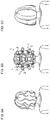
- FIG. 5A shows head hair that is wavy except for base-side portions near the scalp.
- the hair treatment method of the present embodiment is applied to this wavy head hair as shown in FIG. 5B .
- portions of the head hair are separated into a plurality of locks of hair, the locks of hair are inserted into the tubular bodies 2 of hair holders 1 in the above-described manner, the tubular bodies 2 are rolled up into the forms of lock-of-hair holding bodies, and the curling treatment is performed while maintaining the respective wound states (see FIG. 5B ).
- FIG. 5B shows a plurality of locks of hair
- hair-end portions near the hair ends of the locks of hair are placed in the small diameter portions 33 of the lock-of-hair holding bodies, and major portions of hair excluding the hair-end portions are placed in the large diameter portions 31.
- the hair-end portions of the head hair that are placed in the small diameter portions 33 are shaped into inward curls.
- curl shapes with larger roll diameters than the roll diameters of the hair-end portions are imparted to the major portions of the head hair that are placed in the large diameter portions 31; however, the major portions are shaped substantially straight because of the large roll diameters.
- an inward curl refers to a shape of a curl of head hair that is wound in a winding direction closer to the face
- an outward curl refers to a shape of a curl of head hair that is wound in a winding direction away from the face.
- substantially straight shapes may be imparted to the portions of the locks of hair that are placed in the large diameter portions 31, or large curl shapes may be imparted thereto.
- the hair treatment method of the present embodiment it is possible to impart curl shapes with different roll diameters to a lock of hair in a single curling treatment, without having to use a plurality of types of hair holders with different roll diameters. Therefore, the curling operation is simple and easy. Moreover, since it is no longer necessary to perform the curling treatment for each roll diameter, the time required for curling can be reduced.
- the curling treatment can be completed all at once, it is no longer necessary to repeatedly perform the heat treatment of heating a tubular body, or the permanent treatment, as the curling treatment for each roll diameter, and damage to hair caused by these treatments can be reduced.
- the lock of hair that has been subjected to the curling treatment may be subjected to a post-treatment, if necessary.
- a post-treatment hair washing, drying using a drying means such as a dryer, the application of a hair treatment agent, and other treatments can be performed alone or in a combination of two or more.
- the hair treatment agent that may be used in the post-treatment include a hair conditioning agent, a pre-hair-conditioning agent, a styling agent, a hair tonic agent, a hair restoration and hair growth agent, and the like.
- the inner diameter D1 of the large diameter portion 31 is preferably not less than 1.2 times and more preferably not less than 1.5 times the outer diameter D2 of the small diameter portion 33, is preferably not more than 10 times and more preferably not more than 6.5 times the outer diameter D2, and is preferably from 1.2 to 10 times and more preferably from 1.5 to 6.5 times the outer diameter D2.
- an equivalent circle diameter (diameter of a circle that has an area equal to that of the inside of the outline) is used as the inner diameter D1 of the large diameter portion 31.
- an equivalent circle diameter (diameter of a circle that has an area equal to that of the outside of the outline) is used as the outer diameter D2 of the small diameter portion 33. Note that, in a case where the small diameter portion 33 is wound a plurality of turns, the outer diameter of the largest diameter portion of the small diameter portion 33 is regarded as the outer diameter D2 of the small diameter portion 33.
- the curling can be performed at any position in a lock of hair. That is to say, the position to be curled by the hair treatment method of the present invention is not limited, and the hair treatment method can be applied to the entirety or a portion of a lock of hair, depending on the length of the hair, the hairstyle to be set, and the like.
- curling may be performed in a wound state in which a hair-end portion of a lock of hair is placed in the small diameter portion 33 and a portion other than the hair-end portion of the lock of hair is placed in the large diameter portion 31.
- a hair-end portion as used herein refers to a portion near the hair ends of a lock of hair and spans approximately 6 cm from the end of the lock of hair.
- curling may also be performed in a wound state in which a hair-end portion of a lock of hair as well as at least a part of an intermediate portion that is located between the hair-end portion and a base portion are placed in the small diameter portion 33, and the rest of the intermediate portion as well as the base portion, which is located nearer to the base side than the intermediate portion, are placed in the large diameter portion 31.
- the hair treatment method of the present invention can be used to curl the hair prior to the curling treatment or to straighten out the hair that has been subjected to the curling treatment.
- the inner diameter D1 (see FIG. 2B ) of the large diameter portion 31 is preferably 40 mm or greater and more preferably 50 mm or greater, is preferably 100 mm or less and more preferably 80 mm or less, and is preferably from 40 to 100 mm and more preferably from 50 to 80 mm.
- the outer diameter D2 (see FIG. 2B ) of the small diameter portion 33 is preferably 10 mm or greater and more preferably 15 mm or greater, is preferably 40 mm or less and more preferably 35 mm or less, and is preferably from 10 to 40 mm and more preferably from 15 to 35 mm.
- the lock-of-hair holding body 3 has a space S between the large diameter portion 31 and the small diameter portion 33.
- the small diameter portion 33 is located inside the large diameter portion 31, and a portion of an outer circumferential portion of the small diameter portion is contiguous with the large diameter portion 31.
- the portion of the small diameter portion 33 that is contiguous with the large diameter portion 31 is also referred to as a "connecting portion C". In a cross section taken along the aforementioned radial direction, the farther away the small diameter portion 33 is from the connecting portion C, the longer the distance between the small diameter portion 33 and the large diameter portion 31 is.
- the hair treatment method of the present invention it is preferable to curl the lock of hair in a state in which moisture is applied to the lock of hair in advance.
- the moisture is applied to the lock of hair at a stage preferably prior to the rolling-up step, or more preferably prior to the insertion step.
- a styling agent containing water may also be applied.
- a commonly commercially available styling agent can be used as the styling agent.
- components contained in the styling agent other than water include silicone oil, alcohols having 1 to 4 carbon atoms (ethanol, propanol, isopropanol, tert-butyl alcohol, and 1,3-butylene alcohol), cationic polymers, various oil agents, and the like.
- An oil agent is used to improve the hair collectability after drying.
- oil agent examples include hydrocarbons such as squalene, squalane, liquid isoparaffin, light liquid isoparaffin, heavy liquid isoparaffin, ⁇ -olefin oligomers, liquid paraffin, and cycloparaffin; glycerides such as castor oil, cacao oil, mink oil, avocado oil, and olive oil; waxes such as whale wax, lanolin, beeswax, microcrystalline wax, ceresin wax, and carnauba wax; esters such as octyldodecyl myristate, isopropyl myristate, isopropyl palmitate, hexyl laurate, cetyl lactate, propylene glycol monostearate, oleyl oleate, hexadecyl 2-ethylhexanoate, isononyl isononanoate, and tridecyl isononanoate; higher fatty acids such as capric acid, lauric
- the method for applying moisture to the lock of hair is not limited to a specific method, and examples thereof include a method of spraying water or a styling agent onto the lock of hair using a spray or the like and a method of pouring running water over the lock of hair using a shower or the like. Moreover, it is also possible to perform hair washing and the like before performing the hair treatment method and perform the above-described curling in a state in which the hair is not dried or is semi-dried.
- the curling is performed by subjecting the lock of hair held in the tubular body 2 to a permanent treatment.
- the permanent treatment is a treatment for curling by performing an oxidation-reduction treatment, and is usually performed using a permanent wave agent.
- Known permanent wave agents can be used as the permanent wave agent.
- a one-component agent or a two-component agent composed of a first agent containing a reducing agent and a second agent containing an oxidizing agent can be used.
- the reducing agent cleaves disulfide bonds of keratin that constitutes hair, and examples thereof include thioglycollic acid and derivatives thereof, thiolactic acid and derivatives thereof, cystein and derivatives thereof, and salts and the like of these agents.
- the oxidizing agent recombines the cleaved disulfide bonds of keratin in the hair, and examples thereof include potassium bromate, sodium bromate, sodium perborate, and hydrogen peroxide.
- the permanent wave agent can be injected into the tubular body 2 via, for example, a slit, which will be described later.
- the hair holder 1 has an extended portion 4 near an end portion of the opening 21 at the first end of the tubular body 2, the extended portion 4 being constituted by the first surface sheet 23A extending outward in the longitudinal direction X from the tubular body 2.
- the extended portion 4 is integrally formed with the first surface sheet 23A.
- the hair holder need not have the extended portion near the end portion of the opening at the first end, it is preferable that the hair holder has the extended portion, from the standpoint of making it easy to insert the lock of hair into the tubular body.
- the hair holder has the extended portion, because, as will be described later, if the hair holder 1 has a fixing member 5 serving as a fixing means that maintains the tubular body in a wound state, the fixing member 5 can be provided in the extended portion.
- the tubular body 2 is maintained in a wound state in which it is wound to form the lock-of-hair holding body 3 by a fixing means that can maintain the tubular body in the wound state.
- a fixing means that can maintain the tubular body in the wound state.
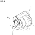
- the hair clip 9 includes a pair of clamp portions. As shown in FIG. 4 , one of the clamp portions of the hair clip 9 is inserted into a space near the central axis of the lock-of-hair holding body 3, and the tubular body 2 is clamped by the pair of clamp portions from both of the inside of that space and the outer circumferential portion side. In this manner, the tubular body is fixed in the wound state.
- An example of other fixing means is a band member that fixes the tubular body 2 in a wound state in which it is wound to form the lock-of-hair holding body 3, by being wound around the large diameter portion 31 or the like.
- the fixing means may be separate from the hair holder.
- the hair holder has the fixing means that maintains the tubular body 2 in a wound state.
- the hair holder 1 of the present embodiment has the fixing member 5 serving as the fixing means.
- the fixing member 5 has a first member 5a and a second member 5b that can be detachably joined to each other.
- the first member 5a is provided on an outer surface of the first surface sheet 23A, or more specifically on an outer surface of the extended portion 4, and the second member 5b is provided on an outer surface of the second surface sheet 23B.
- the "outer surfaces” means the surfaces on the opposite side to the surfaces that form the space into which the lock of hair can be inserted.
- the first member 5a is joined to the second member 5b that is located in the large diameter portion 31, and thus the tubular body 2 can be maintained in the wound state in which it is wound to form the lock-of-hair holding body 3.
- a joint member, or a male and female member, constituted by a plurality of members that can be detachably joined to each other can be suitably used as the fixing member 5.
- the joint member include an adherend-selective pressure-sensitive adhesive tape, a magnet, and the like.
- the male and female member include a hook and eye, a mechanical hook-and-loop fastener, and the like.
- the adherend-selective pressure-sensitive adhesive tape is a pressure-sensitive adhesive tape that adheres only to a particular substance and substantially does not adhere to any other substances.
- the wording "substantially does not adhere” includes not only a case where the adherend-selective pressure-sensitive adhesive tape does not create an adhesion state with any substance other than the particular substance but also a case where, even though the adherend-selective pressure-sensitive adhesive tape creates an adhesion state with a substance other than the particular substance, the adhesion state quickly disappears if a slight relative movement occurs between that substance and the adherend-selective pressure-sensitive adhesive tape.
- Such an adherend-selective pressure-sensitive adhesive tape includes a tape base material and a self-adhesive agent applied to the tape base material, and the self-adhesive agent adheres only to a substance of the same kind and substantially does not adhere to other substances. That is to say, the self-adhesive agent has adhesiveness only to the self-adhesive agent itself.
- a pressure-sensitive adhesive tape including a self-adhesive agent and a tape base material disclosed in JP 2007-167192A can be used.
- the hair holder and a fixing means which is an alternative fixing means of the above-mentioned fixing member may be separately provided.
- the alternative fixing means is preferably a clip.
- the alternative fixing means may be removably attached to the hair holder to maintain the tubular body, which has a first surface sheet and a second surface sheet, in the wound state. When the tubular body is rolled up, the first surface sheet is located on the inside of the tubular body and the second surface sheet is located on the outside of the tubular body.
- Such alternative fixing means may be made of suitable materials.
- the suitable materials are preferably selected from the group consisting of plastics, glass, ceramics and metal. It is preferred that the alternative fixing means is a clip made of plastics or metal.
- the hair holder 1 is not necessarily required to have a slit.
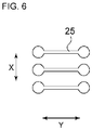
- the hair holder 1 of the present embodiment has a plurality of slits 25 that are intermittently arranged in either one of the surfaces of the tubular body 2 along the longitudinal direction X of the tubular body 2.
- Each of the slits 25 extends in the width direction Y.
- the hair holder has a plurality of slits 25 that are arranged in series along the longitudinal direction X, in either one of the surfaces of the tubular body 2. In this case, it is sufficient that the slits are formed in one or the other surface constituting the tubular body 2, and the slits may also be formed in both of the surfaces.
- the hair holder 1 of the present embodiment has the plurality of slits 25 in the second surface sheet 23B, which is located on the outside when the tubular body is rolled up, and each of the slits 25 extends in the width direction Y. Moreover, in the present embodiment, the slits penetrate the second surface sheet 23B in its thickness direction.
- the slits may each have circular portions at both end portions thereof.
- the two end portions of each slit shown in FIG. 6 may be formed in a circular shape through punching, for example.
- the hair holder 1 of the present embodiment has winding and tightening tabs 8 in the opposite side edge portions, respectively, of the tubular body 2, the winding and tightening tabs 8 being located near the opening 22 at the second end.
- the winding and tightening tabs 8 extend outward in the width direction Y from the tubular body 2 and are integrally formed with the first surface sheet 23A, and each have a semicircular shape in a plan view. Due to the hair holder having the winding and tightening tabs, the tubular body can be rolled up easily, and tightly, if necessary, by rolling up the tubular body by holding the winding and tightening tabs with hands.
- the formation method, shape, size, thickness, arrangement, and the like of the winding and tightening tabs 8 can be set appropriately.
- the hair holder of the above-described embodiment after the lock-of-hair holding body 3 has been formed by performing the rolling-up in such a manner that the large diameter portion 31 and the small diameter portion 33 are formed, the form of the lock-of-hair holding body 3 is maintained using the fixing means.
- the tubular body in its natural state is rolled up so that the large diameter portion 31 and the small diameter portion 33 are formed.
- this hair holder will also be referred to as a double-ring hair holder.
- a tubular body in its natural state is wound into the form of the lock-of-hair holding body 3 as shown in FIGS. 2A and 2B , and this form can be maintained without using the aforementioned fixing means.
- the double-ring hair holder is configured such that, after stretching out the tubular body, the tubular body automatically rolls up into the form of the lock-of-hair holding body 3 upon being released from the stretched state.
- This tubular body can be obtained by using a shape memory sheet for either or both of the two sheets constituting the tubular body and making the shape memory sheet retain a state in which it is rolled up into the form of the lock-of-hair holding body 3.
- the shape memory sheet In order to make the shape memory sheet retain such a state, for example, the shape memory sheet is rolled up so that the large diameter portion 31 and the small diameter portion 33 are formed, and the shape memory sheet is heated in this rolled-up state.
- the double-ring hair holder can have a configuration similar to that of the above-described hair holder except that the tubular body in its natural state is rolled up so that the large diameter portion 31 and the small diameter portion 33 are formed.
- the maximum distance between the large diameter portion 31 and the small diameter portion 33 is 5 mm or greater.
- the inner diameter D1 of the large diameter portion 31 of the double-ring hair holder is preferably not less than 1.2 times and more preferably not less than 1.5 times the outer diameter D2 of the small diameter portion 33, is preferably not more than 10 times and more preferably not more than 6.5 times the outer diameter D2, and is preferably from 1.2 to 10 times and more preferably from 1.5 to 6.5 times the outer diameter D2.
- a hair treatment method that uses the double-ring hair holder includes an insertion step, a rolling-up step, and a curling step.
- the tubular body automatically rolls up so as to form the large diameter portion 31 and the small diameter portion 33. That is to say, the lock-of-hair holding body 3 is automatically formed.
- the curling treatment step the curing treatment is performed on the lock of hair without using a fixing means.
- Examples of the material for forming a sheet constituting the tubular body include a nonwoven fabric (polyethylene nonwoven fabric, polyethylene terephthalate nonwoven fabric, or the like), a woven fabric, a net-like sheet, a porous or non-porous resin film (polyethylene film, polyethylene terephthalate film, or the like), paper, a polymer material sheet, a rubber sheet, a composite of these materials, or the like.
- the tubular body may be entirely or partially made of a shape memory sheet described above. In this case, amorphous polyethylene terephthalate (A-PET) or the like may be used as the shape memory resin contained in the shape memory sheet.
- A-PET amorphous polyethylene terephthalate
- each of the first surface sheet and the second surface sheet is preferably 5 ⁇ m or greater and more preferably 10 ⁇ m or greater, is preferably 2,000 ⁇ m or less and more preferably 1,500 ⁇ m or less, and is preferably from 5 to 2,000 ⁇ m and more preferably from 10 to 1,500 ⁇ m.
- a sheet that constitutes the tubular body is subjected to processing for improving the diffusibility of the hair treatment agent such as a permanent wave agent.
- processing include, but are not limited to, embossing, calendering, resin film formation, and the like.
- embossing can improve the diffusibility by forming protrusions successively arranged in the longitudinal direction of the sheet and thereby allowing the hair treatment agent to flow along the protrusions.
- the calendering can improve the diffusibility of the hair treatment agent by adjusting the density of the sheet that constitutes the tubular body.
- the resin film formation can improve the diffusibility of the hair treatment agent by forming a resin film with low liquid absorbency partially or entirely on the sheet that constitutes the tubular body and thereby reducing the total liquid absorption amount of the sheet.
- the dimensions and the like of the tubular body 2 can be appropriately determined in accordance with the length of hair, the section of hair that is desired to be curled, and the volume of a lock of hair to be inserted, but are preferably within the following ranges.
- the length W2 (see FIG. 1B ) of the tubular body 2 in the width direction Y is preferably 25 mm or greater and more preferably 30 mm or greater, is preferably 200 mm or less and more preferably 150 mm or less, and is preferably from 25 to 200 mm and more preferably from 30 to 150 mm.
- the length L1 (see FIG. 1B ) of the hair holder 1 in the longitudinal direction X is preferably 50 mm or greater and more preferably 100 mm or greater, is preferably 400 mm or less and more preferably 350 mm or less, and is preferably from 50 to 400 mm and more preferably from 100 to 350 mm.
- the length L1 of the hair holder 1 in the longitudinal direction X is the sum of the lengths of the extended portion 4 and the tubular body 2 in the longitudinal direction X.
- the length L2 of the tubular body 2 in the longitudinal direction X is preferably 45 mm or greater and more preferably 90 mm or greater, is preferably 300 mm or less and more preferably 275 mm or less, and is preferably from 45 to 300 mm and more preferably from 90 to 275 mm.
- an end portion of the tubular body 2 of the present embodiment on the opening 21 side at the first end is curved into a concave shape curving inward in the longitudinal direction X.
- the maximum length of the tubular body 2 in the longitudinal direction X is within the aforementioned range.
- the length W22 (see FIG. 1B ) in the width direction Y, of the opening 22 at the second end relative to the length W2 of the tubular body 2 in the width direction Y is preferably 40.0% or greater and more preferably 66.7% or greater, is preferably 97.5% or less and more preferably 96.7% or less, and is preferably from 40.0% to 97.5% and more preferably from 66.7% to 96.7%.
- the length W22 (see FIG. 1B ) in the width direction Y, of the opening 22 at the second end is preferably 10 mm or greater and more preferably 20 mm or greater, is preferably 195 mm or less and more preferably 145 mm or less, and is preferably from 10 to 195 mm and more preferably from 20 to 145 mm.
- the length W22 in the width direction Y of the opening 22 at the second end is equal to the length in the width direction Y of the opening 21 at the first end.
- the length of the opening 22 at the second end and the length of the opening 21 at the first end may be equal to each other or may be different from each other.
- the slits extending in the width direction of the second surface sheet 23B means slits with a width of less than 3 mm.
- the length W6 (see FIG. 1A ) of the slits 25 in the width direction Y relative to the length W2 of the tubular body 2 in the width direction Y is preferably 40.0% or greater and more preferably 50.0% or greater, is preferably 90.0% or less and more preferably 80.0% or less, and is preferably from 40.0% to 90.0% and more preferably from 50.0% to 80.0%.
- the length W6 (see FIG. 1A ) of the slits 25 in the width direction Y is preferably 10 mm or greater and more preferably 15 mm or greater, is preferably 180 mm or less and more preferably 120 mm or less, and is preferably from 10 to 180 mm and more preferably from 15 to 120 mm.
- the tubular body of the hair holder can be formed by superposing two sheets one on top of the other and integrating side portions of the two sheets along their longitudinal direction.
- the tubular body of the hair holder can be formed by folding a single sheet into a rectangular shape in a plan view, and integrating side portions of the sheet that extend along its longitudinal direction and overlap each other.
- a sheet for forming the tubular body can be produced from a raw material sheet by punching the raw material sheet into a desired shape.
- Examples of the method for integrating sheets for forming the tubular body, that is, the method for forming the pair of side joint portions 24 include fusion bonding such as heat sealing or ultrasonic sealing, adhesion using an adhesive or the like, sewing, and the like.
- the hair treatment method and the hair holder of the present invention are not limited to the foregoing embodiments, and appropriate changes can be made thereto without departing from the gist of the present invention.
- the shape and the surface of a sheet material that constitutes the tubular body may be a surface that has protrusions and depressions or may be a flat surface.
- the present invention further discloses the following hair treatment methods and hair holders.
- curl shapes with different roll shapes can be imparted to a lock of hair in a single curling treatment.
Landscapes
- Hair Curling (AREA)
Priority Applications (5)
| Application Number | Priority Date | Filing Date | Title |
|---|---|---|---|
| EP19154958.3A EP3689179B1 (de) | 2019-02-01 | 2019-02-01 | Haarbehandlungsverfahren und haarhalter |
| CN202080011819.1A CN113382658A (zh) | 2019-02-01 | 2020-01-22 | 毛发处理方法和毛发保持具 |
| PCT/IB2020/050483 WO2020157605A1 (ja) | 2019-02-01 | 2020-01-22 | 毛髪処理方法及び毛髪保持具 |
| US17/297,187 US20220022617A1 (en) | 2019-02-01 | 2020-01-22 | Hair treatment method and hair holder |
| TW109102665A TW202038805A (zh) | 2019-02-01 | 2020-01-22 | 毛髮處理方法及毛髮保持具 |
Applications Claiming Priority (1)
| Application Number | Priority Date | Filing Date | Title |
|---|---|---|---|
| EP19154958.3A EP3689179B1 (de) | 2019-02-01 | 2019-02-01 | Haarbehandlungsverfahren und haarhalter |
Publications (2)
| Publication Number | Publication Date |
|---|---|
| EP3689179A1 true EP3689179A1 (de) | 2020-08-05 |
| EP3689179B1 EP3689179B1 (de) | 2022-01-05 |
Family
ID=65365786
Family Applications (1)
| Application Number | Title | Priority Date | Filing Date |
|---|---|---|---|
| EP19154958.3A Active EP3689179B1 (de) | 2019-02-01 | 2019-02-01 | Haarbehandlungsverfahren und haarhalter |
Country Status (5)
| Country | Link |
|---|---|
| US (1) | US20220022617A1 (de) |
| EP (1) | EP3689179B1 (de) |
| CN (1) | CN113382658A (de) |
| TW (1) | TW202038805A (de) |
| WO (1) | WO2020157605A1 (de) |
Cited By (1)
| Publication number | Priority date | Publication date | Assignee | Title |
|---|---|---|---|---|
| US11452351B2 (en) | 2019-02-01 | 2022-09-27 | Kao Corporation | Hair holder, method for producing said hair holder, and method for using said hair holder |
Families Citing this family (1)
| Publication number | Priority date | Publication date | Assignee | Title |
|---|---|---|---|---|
| USD979838S1 (en) * | 2019-06-26 | 2023-02-28 | Kao Corporation | Hair holder |
Citations (6)
| Publication number | Priority date | Publication date | Assignee | Title |
|---|---|---|---|---|
| US3255765A (en) | 1962-10-16 | 1966-06-14 | Jules H Heims | Automatic coiling hair curler |
| JPH10192036A (ja) | 1997-01-10 | 1998-07-28 | White House Kk | 毛髪巻取具およびそれを用いた毛髪巻取方法 |
| WO1999012445A1 (en) * | 1997-09-10 | 1999-03-18 | Masood Habibi | Adjustable hair curler |
| JP2004209237A (ja) * | 2002-12-17 | 2004-07-29 | Kao Corp | 毛髪保持具 |
| EP1535530A1 (de) * | 2002-07-25 | 2005-06-01 | Kao Corporation | Haarhalter |
| JP2007167192A (ja) | 2005-12-20 | 2007-07-05 | Kao Corp | パンツ型使い捨ておむつ |
Family Cites Families (3)
| Publication number | Priority date | Publication date | Assignee | Title |
|---|---|---|---|---|
| CN100455230C (zh) * | 2004-06-03 | 2009-01-28 | 木俣年博 | 卷发器具以及卷发方法 |
| CN101262794A (zh) * | 2005-09-12 | 2008-09-10 | 花王株式会社 | 毛发保持具 |
| CN103099419A (zh) * | 2012-08-23 | 2013-05-15 | 李汉江 | 一种卷曲毛发的装置以及卷绕方法 |
-
2019
- 2019-02-01 EP EP19154958.3A patent/EP3689179B1/de active Active
-
2020
- 2020-01-22 TW TW109102665A patent/TW202038805A/zh unknown
- 2020-01-22 WO PCT/IB2020/050483 patent/WO2020157605A1/ja not_active Ceased
- 2020-01-22 US US17/297,187 patent/US20220022617A1/en not_active Abandoned
- 2020-01-22 CN CN202080011819.1A patent/CN113382658A/zh active Pending
Patent Citations (6)
| Publication number | Priority date | Publication date | Assignee | Title |
|---|---|---|---|---|
| US3255765A (en) | 1962-10-16 | 1966-06-14 | Jules H Heims | Automatic coiling hair curler |
| JPH10192036A (ja) | 1997-01-10 | 1998-07-28 | White House Kk | 毛髪巻取具およびそれを用いた毛髪巻取方法 |
| WO1999012445A1 (en) * | 1997-09-10 | 1999-03-18 | Masood Habibi | Adjustable hair curler |
| EP1535530A1 (de) * | 2002-07-25 | 2005-06-01 | Kao Corporation | Haarhalter |
| JP2004209237A (ja) * | 2002-12-17 | 2004-07-29 | Kao Corp | 毛髪保持具 |
| JP2007167192A (ja) | 2005-12-20 | 2007-07-05 | Kao Corp | パンツ型使い捨ておむつ |
Cited By (1)
| Publication number | Priority date | Publication date | Assignee | Title |
|---|---|---|---|---|
| US11452351B2 (en) | 2019-02-01 | 2022-09-27 | Kao Corporation | Hair holder, method for producing said hair holder, and method for using said hair holder |
Also Published As
| Publication number | Publication date |
|---|---|
| CN113382658A (zh) | 2021-09-10 |
| EP3689179B1 (de) | 2022-01-05 |
| TW202038805A (zh) | 2020-11-01 |
| WO2020157605A1 (ja) | 2020-08-06 |
| US20220022617A1 (en) | 2022-01-27 |
Similar Documents
| Publication | Publication Date | Title |
|---|---|---|
| US7500487B2 (en) | Hair treating implement | |
| JP3998529B2 (ja) | 毛髪保持具 | |
| EP3689179B1 (de) | Haarbehandlungsverfahren und haarhalter | |
| EP3689178B1 (de) | Haarbehandlungsverfahren und haarhalter | |
| EP3689177B1 (de) | Haarbehandlungsverfahren und haarhalter | |
| EP3918948B1 (de) | Haarhalter, verfahren zur herstellung des haarhalters und verwendung des haarhalters | |
| US5810024A (en) | Touch-up kit | |
| JP2004209237A (ja) | 毛髪保持具 | |
| JP2018153483A (ja) | 毛髪保持具 | |
| JP2684509B2 (ja) | パーマネントウエーブ施術方法およびその施術器具 | |
| JP2019080721A (ja) | 毛髪保持具 | |
| JP3013861U (ja) | 電動式毛髪巻き器 | |
| US20100051044A1 (en) | Hair Curler Device and Methods of Use | |
| JP2005253947A (ja) | 美容施術用パウチとその構成部材、及び美容施術方法 | |
| JP2007167689A (ja) | 毛髪保持具 | |
| JPH0870926A (ja) | ヘアカール用具 | |
| JP2011206236A (ja) | パーマネントウェーブ形成器具及びパーマネントウェーブ処理方法 |
Legal Events
| Date | Code | Title | Description |
|---|---|---|---|
| PUAI | Public reference made under article 153(3) epc to a published international application that has entered the european phase |
Free format text: ORIGINAL CODE: 0009012 |
|
| STAA | Information on the status of an ep patent application or granted ep patent |
Free format text: STATUS: THE APPLICATION HAS BEEN PUBLISHED |
|
| AK | Designated contracting states |
Kind code of ref document: A1 Designated state(s): AL AT BE BG CH CY CZ DE DK EE ES FI FR GB GR HR HU IE IS IT LI LT LU LV MC MK MT NL NO PL PT RO RS SE SI SK SM TR |
|
| AX | Request for extension of the european patent |
Extension state: BA ME |
|
| STAA | Information on the status of an ep patent application or granted ep patent |
Free format text: STATUS: REQUEST FOR EXAMINATION WAS MADE |
|
| 17P | Request for examination filed |
Effective date: 20210114 |
|
| RBV | Designated contracting states (corrected) |
Designated state(s): AL AT BE BG CH CY CZ DE DK EE ES FI FR GB GR HR HU IE IS IT LI LT LU LV MC MK MT NL NO PL PT RO RS SE SI SK SM TR |
|
| GRAP | Despatch of communication of intention to grant a patent |
Free format text: ORIGINAL CODE: EPIDOSNIGR1 |
|
| STAA | Information on the status of an ep patent application or granted ep patent |
Free format text: STATUS: GRANT OF PATENT IS INTENDED |
|
| INTG | Intention to grant announced |
Effective date: 20210707 |
|
| GRAJ | Information related to disapproval of communication of intention to grant by the applicant or resumption of examination proceedings by the epo deleted |
Free format text: ORIGINAL CODE: EPIDOSDIGR1 |
|
| STAA | Information on the status of an ep patent application or granted ep patent |
Free format text: STATUS: REQUEST FOR EXAMINATION WAS MADE |
|
| GRAP | Despatch of communication of intention to grant a patent |
Free format text: ORIGINAL CODE: EPIDOSNIGR1 |
|
| STAA | Information on the status of an ep patent application or granted ep patent |
Free format text: STATUS: GRANT OF PATENT IS INTENDED |
|
| INTC | Intention to grant announced (deleted) | ||
| GRAS | Grant fee paid |
Free format text: ORIGINAL CODE: EPIDOSNIGR3 |
|
| INTG | Intention to grant announced |
Effective date: 20211028 |
|
| GRAA | (expected) grant |
Free format text: ORIGINAL CODE: 0009210 |
|
| STAA | Information on the status of an ep patent application or granted ep patent |
Free format text: STATUS: THE PATENT HAS BEEN GRANTED |
|
| AK | Designated contracting states |
Kind code of ref document: B1 Designated state(s): AL AT BE BG CH CY CZ DE DK EE ES FI FR GB GR HR HU IE IS IT LI LT LU LV MC MK MT NL NO PL PT RO RS SE SI SK SM TR |
|
| REG | Reference to a national code |
Ref country code: GB Ref legal event code: FG4D |
|
| REG | Reference to a national code |
Ref country code: CH Ref legal event code: EP |
|
| REG | Reference to a national code |
Ref country code: AT Ref legal event code: REF Ref document number: 1459747 Country of ref document: AT Kind code of ref document: T Effective date: 20220115 |
|
| REG | Reference to a national code |
Ref country code: DE Ref legal event code: R096 Ref document number: 602019010546 Country of ref document: DE |
|
| REG | Reference to a national code |
Ref country code: IE Ref legal event code: FG4D |
|
| REG | Reference to a national code |
Ref country code: LT Ref legal event code: MG9D |
|
| REG | Reference to a national code |
Ref country code: NL Ref legal event code: MP Effective date: 20220105 |
|
| REG | Reference to a national code |
Ref country code: AT Ref legal event code: MK05 Ref document number: 1459747 Country of ref document: AT Kind code of ref document: T Effective date: 20220105 |
|
| PG25 | Lapsed in a contracting state [announced via postgrant information from national office to epo] |
Ref country code: NL Free format text: LAPSE BECAUSE OF FAILURE TO SUBMIT A TRANSLATION OF THE DESCRIPTION OR TO PAY THE FEE WITHIN THE PRESCRIBED TIME-LIMIT Effective date: 20220105 |
|
| PG25 | Lapsed in a contracting state [announced via postgrant information from national office to epo] |
Ref country code: SE Free format text: LAPSE BECAUSE OF FAILURE TO SUBMIT A TRANSLATION OF THE DESCRIPTION OR TO PAY THE FEE WITHIN THE PRESCRIBED TIME-LIMIT Effective date: 20220105 Ref country code: RS Free format text: LAPSE BECAUSE OF FAILURE TO SUBMIT A TRANSLATION OF THE DESCRIPTION OR TO PAY THE FEE WITHIN THE PRESCRIBED TIME-LIMIT Effective date: 20220105 Ref country code: PT Free format text: LAPSE BECAUSE OF FAILURE TO SUBMIT A TRANSLATION OF THE DESCRIPTION OR TO PAY THE FEE WITHIN THE PRESCRIBED TIME-LIMIT Effective date: 20220505 Ref country code: NO Free format text: LAPSE BECAUSE OF FAILURE TO SUBMIT A TRANSLATION OF THE DESCRIPTION OR TO PAY THE FEE WITHIN THE PRESCRIBED TIME-LIMIT Effective date: 20220405 Ref country code: LT Free format text: LAPSE BECAUSE OF FAILURE TO SUBMIT A TRANSLATION OF THE DESCRIPTION OR TO PAY THE FEE WITHIN THE PRESCRIBED TIME-LIMIT Effective date: 20220105 Ref country code: HR Free format text: LAPSE BECAUSE OF FAILURE TO SUBMIT A TRANSLATION OF THE DESCRIPTION OR TO PAY THE FEE WITHIN THE PRESCRIBED TIME-LIMIT Effective date: 20220105 Ref country code: ES Free format text: LAPSE BECAUSE OF FAILURE TO SUBMIT A TRANSLATION OF THE DESCRIPTION OR TO PAY THE FEE WITHIN THE PRESCRIBED TIME-LIMIT Effective date: 20220105 Ref country code: BG Free format text: LAPSE BECAUSE OF FAILURE TO SUBMIT A TRANSLATION OF THE DESCRIPTION OR TO PAY THE FEE WITHIN THE PRESCRIBED TIME-LIMIT Effective date: 20220405 |
|
| PG25 | Lapsed in a contracting state [announced via postgrant information from national office to epo] |
Ref country code: PL Free format text: LAPSE BECAUSE OF FAILURE TO SUBMIT A TRANSLATION OF THE DESCRIPTION OR TO PAY THE FEE WITHIN THE PRESCRIBED TIME-LIMIT Effective date: 20220105 Ref country code: LV Free format text: LAPSE BECAUSE OF FAILURE TO SUBMIT A TRANSLATION OF THE DESCRIPTION OR TO PAY THE FEE WITHIN THE PRESCRIBED TIME-LIMIT Effective date: 20220105 Ref country code: GR Free format text: LAPSE BECAUSE OF FAILURE TO SUBMIT A TRANSLATION OF THE DESCRIPTION OR TO PAY THE FEE WITHIN THE PRESCRIBED TIME-LIMIT Effective date: 20220406 Ref country code: FI Free format text: LAPSE BECAUSE OF FAILURE TO SUBMIT A TRANSLATION OF THE DESCRIPTION OR TO PAY THE FEE WITHIN THE PRESCRIBED TIME-LIMIT Effective date: 20220105 Ref country code: AT Free format text: LAPSE BECAUSE OF FAILURE TO SUBMIT A TRANSLATION OF THE DESCRIPTION OR TO PAY THE FEE WITHIN THE PRESCRIBED TIME-LIMIT Effective date: 20220105 |
|
| PG25 | Lapsed in a contracting state [announced via postgrant information from national office to epo] |
Ref country code: IS Free format text: LAPSE BECAUSE OF FAILURE TO SUBMIT A TRANSLATION OF THE DESCRIPTION OR TO PAY THE FEE WITHIN THE PRESCRIBED TIME-LIMIT Effective date: 20220505 |
|
| REG | Reference to a national code |
Ref country code: DE Ref legal event code: R097 Ref document number: 602019010546 Country of ref document: DE |
|
| REG | Reference to a national code |
Ref country code: CH Ref legal event code: PL |
|
| REG | Reference to a national code |
Ref country code: BE Ref legal event code: MM Effective date: 20220228 |
|
| PG25 | Lapsed in a contracting state [announced via postgrant information from national office to epo] |
Ref country code: SM Free format text: LAPSE BECAUSE OF FAILURE TO SUBMIT A TRANSLATION OF THE DESCRIPTION OR TO PAY THE FEE WITHIN THE PRESCRIBED TIME-LIMIT Effective date: 20220105 Ref country code: SK Free format text: LAPSE BECAUSE OF FAILURE TO SUBMIT A TRANSLATION OF THE DESCRIPTION OR TO PAY THE FEE WITHIN THE PRESCRIBED TIME-LIMIT Effective date: 20220105 Ref country code: RO Free format text: LAPSE BECAUSE OF FAILURE TO SUBMIT A TRANSLATION OF THE DESCRIPTION OR TO PAY THE FEE WITHIN THE PRESCRIBED TIME-LIMIT Effective date: 20220105 Ref country code: MC Free format text: LAPSE BECAUSE OF FAILURE TO SUBMIT A TRANSLATION OF THE DESCRIPTION OR TO PAY THE FEE WITHIN THE PRESCRIBED TIME-LIMIT Effective date: 20220105 Ref country code: LU Free format text: LAPSE BECAUSE OF NON-PAYMENT OF DUE FEES Effective date: 20220201 Ref country code: EE Free format text: LAPSE BECAUSE OF FAILURE TO SUBMIT A TRANSLATION OF THE DESCRIPTION OR TO PAY THE FEE WITHIN THE PRESCRIBED TIME-LIMIT Effective date: 20220105 Ref country code: DK Free format text: LAPSE BECAUSE OF FAILURE TO SUBMIT A TRANSLATION OF THE DESCRIPTION OR TO PAY THE FEE WITHIN THE PRESCRIBED TIME-LIMIT Effective date: 20220105 Ref country code: CZ Free format text: LAPSE BECAUSE OF FAILURE TO SUBMIT A TRANSLATION OF THE DESCRIPTION OR TO PAY THE FEE WITHIN THE PRESCRIBED TIME-LIMIT Effective date: 20220105 |
|
| PLBE | No opposition filed within time limit |
Free format text: ORIGINAL CODE: 0009261 |
|
| STAA | Information on the status of an ep patent application or granted ep patent |
Free format text: STATUS: NO OPPOSITION FILED WITHIN TIME LIMIT |
|
| PG25 | Lapsed in a contracting state [announced via postgrant information from national office to epo] |
Ref country code: AL Free format text: LAPSE BECAUSE OF FAILURE TO SUBMIT A TRANSLATION OF THE DESCRIPTION OR TO PAY THE FEE WITHIN THE PRESCRIBED TIME-LIMIT Effective date: 20220105 |
|
| 26N | No opposition filed |
Effective date: 20221006 |
|
| PG25 | Lapsed in a contracting state [announced via postgrant information from national office to epo] |
Ref country code: LI Free format text: LAPSE BECAUSE OF NON-PAYMENT OF DUE FEES Effective date: 20220228 Ref country code: IE Free format text: LAPSE BECAUSE OF NON-PAYMENT OF DUE FEES Effective date: 20220201 Ref country code: CH Free format text: LAPSE BECAUSE OF NON-PAYMENT OF DUE FEES Effective date: 20220228 |
|
| PG25 | Lapsed in a contracting state [announced via postgrant information from national office to epo] |
Ref country code: SI Free format text: LAPSE BECAUSE OF FAILURE TO SUBMIT A TRANSLATION OF THE DESCRIPTION OR TO PAY THE FEE WITHIN THE PRESCRIBED TIME-LIMIT Effective date: 20220105 Ref country code: BE Free format text: LAPSE BECAUSE OF NON-PAYMENT OF DUE FEES Effective date: 20220228 |
|
| P01 | Opt-out of the competence of the unified patent court (upc) registered |
Effective date: 20230522 |
|
| PG25 | Lapsed in a contracting state [announced via postgrant information from national office to epo] |
Ref country code: IT Free format text: LAPSE BECAUSE OF FAILURE TO SUBMIT A TRANSLATION OF THE DESCRIPTION OR TO PAY THE FEE WITHIN THE PRESCRIBED TIME-LIMIT Effective date: 20220105 |
|
| PG25 | Lapsed in a contracting state [announced via postgrant information from national office to epo] |
Ref country code: MK Free format text: LAPSE BECAUSE OF FAILURE TO SUBMIT A TRANSLATION OF THE DESCRIPTION OR TO PAY THE FEE WITHIN THE PRESCRIBED TIME-LIMIT Effective date: 20220105 Ref country code: CY Free format text: LAPSE BECAUSE OF FAILURE TO SUBMIT A TRANSLATION OF THE DESCRIPTION OR TO PAY THE FEE WITHIN THE PRESCRIBED TIME-LIMIT Effective date: 20220105 |
|
| PG25 | Lapsed in a contracting state [announced via postgrant information from national office to epo] |
Ref country code: HU Free format text: LAPSE BECAUSE OF FAILURE TO SUBMIT A TRANSLATION OF THE DESCRIPTION OR TO PAY THE FEE WITHIN THE PRESCRIBED TIME-LIMIT; INVALID AB INITIO Effective date: 20190201 |
|
| PG25 | Lapsed in a contracting state [announced via postgrant information from national office to epo] |
Ref country code: TR Free format text: LAPSE BECAUSE OF FAILURE TO SUBMIT A TRANSLATION OF THE DESCRIPTION OR TO PAY THE FEE WITHIN THE PRESCRIBED TIME-LIMIT Effective date: 20220105 |
|
| PG25 | Lapsed in a contracting state [announced via postgrant information from national office to epo] |
Ref country code: MT Free format text: LAPSE BECAUSE OF FAILURE TO SUBMIT A TRANSLATION OF THE DESCRIPTION OR TO PAY THE FEE WITHIN THE PRESCRIBED TIME-LIMIT Effective date: 20220105 |
|
| PGFP | Annual fee paid to national office [announced via postgrant information from national office to epo] |
Ref country code: GB Payment date: 20241227 Year of fee payment: 7 |
|
| PGFP | Annual fee paid to national office [announced via postgrant information from national office to epo] |
Ref country code: DE Payment date: 20241231 Year of fee payment: 7 |
|
| PGFP | Annual fee paid to national office [announced via postgrant information from national office to epo] |
Ref country code: FR Payment date: 20251231 Year of fee payment: 8 |