EP3687701B1 - Applicateur à interval de buses réduit - Google Patents
Applicateur à interval de buses réduit Download PDFInfo
- Publication number
- EP3687701B1 EP3687701B1 EP18782913.0A EP18782913A EP3687701B1 EP 3687701 B1 EP3687701 B1 EP 3687701B1 EP 18782913 A EP18782913 A EP 18782913A EP 3687701 B1 EP3687701 B1 EP 3687701B1
- Authority
- EP
- European Patent Office
- Prior art keywords
- nozzles
- valve
- flow channels
- actuators
- actuator
- Prior art date
- Legal status (The legal status is an assumption and is not a legal conclusion. Google has not performed a legal analysis and makes no representation as to the accuracy of the status listed.)
- Active
Links
- 239000011248 coating agent Substances 0.000 claims description 66
- 239000012528 membrane Substances 0.000 claims description 37
- 238000007789 sealing Methods 0.000 claims description 19
- 239000000758 substrate Substances 0.000 claims description 10
- -1 polyoxymethylene Polymers 0.000 claims description 9
- 229920003229 poly(methyl methacrylate) Polymers 0.000 claims description 6
- 229920002647 polyamide Polymers 0.000 claims description 6
- 229920002530 polyetherether ketone Polymers 0.000 claims description 6
- 229920000573 polyethylene Polymers 0.000 claims description 6
- 229920006324 polyoxymethylene Polymers 0.000 claims description 6
- 229920001155 polypropylene Polymers 0.000 claims description 6
- 238000010422 painting Methods 0.000 claims description 5
- 239000003973 paint Substances 0.000 claims description 4
- 239000004033 plastic Substances 0.000 claims description 4
- 229920003023 plastic Polymers 0.000 claims description 4
- 229920000515 polycarbonate Polymers 0.000 claims description 4
- WKBPZYKAUNRMKP-UHFFFAOYSA-N 1-[2-(2,4-dichlorophenyl)pentyl]1,2,4-triazole Chemical compound C=1C=C(Cl)C=C(Cl)C=1C(CCC)CN1C=NC=N1 WKBPZYKAUNRMKP-UHFFFAOYSA-N 0.000 claims description 3
- 229930040373 Paraformaldehyde Natural products 0.000 claims description 3
- 239000004696 Poly ether ether ketone Substances 0.000 claims description 3
- 239000004952 Polyamide Substances 0.000 claims description 3
- 239000004698 Polyethylene Substances 0.000 claims description 3
- 239000004743 Polypropylene Substances 0.000 claims description 3
- 229920001577 copolymer Polymers 0.000 claims description 3
- 239000000463 material Substances 0.000 claims description 3
- 229920001643 poly(ether ketone) Polymers 0.000 claims description 3
- 229920001652 poly(etherketoneketone) Polymers 0.000 claims description 3
- 239000004926 polymethyl methacrylate Substances 0.000 claims description 3
- 239000004793 Polystyrene Substances 0.000 claims description 2
- 238000000576 coating method Methods 0.000 claims description 2
- 239000012530 fluid Substances 0.000 claims description 2
- 239000011521 glass Substances 0.000 claims description 2
- 239000004417 polycarbonate Substances 0.000 claims description 2
- 239000010703 silicon Substances 0.000 claims description 2
- 229910052710 silicon Inorganic materials 0.000 claims description 2
- 239000010935 stainless steel Substances 0.000 claims description 2
- 229910001220 stainless steel Inorganic materials 0.000 claims description 2
- 230000001419 dependent effect Effects 0.000 claims 7
- 239000011031 topaz Substances 0.000 claims 1
- 229910052853 topaz Inorganic materials 0.000 claims 1
- 238000000034 method Methods 0.000 description 7
- 230000004048 modification Effects 0.000 description 4
- 238000012986 modification Methods 0.000 description 4
- 230000008569 process Effects 0.000 description 4
- 230000001427 coherent effect Effects 0.000 description 3
- 239000000853 adhesive Substances 0.000 description 2
- 230000001070 adhesive effect Effects 0.000 description 2
- 238000006073 displacement reaction Methods 0.000 description 2
- 238000004519 manufacturing process Methods 0.000 description 2
- 229920002223 polystyrene Polymers 0.000 description 2
- 230000009467 reduction Effects 0.000 description 2
- 239000007921 spray Substances 0.000 description 2
- 238000010146 3D printing Methods 0.000 description 1
- 241000237369 Helix pomatia Species 0.000 description 1
- 230000009471 action Effects 0.000 description 1
- 230000004913 activation Effects 0.000 description 1
- 238000004026 adhesive bonding Methods 0.000 description 1
- 230000008901 benefit Effects 0.000 description 1
- 238000011161 development Methods 0.000 description 1
- 230000018109 developmental process Effects 0.000 description 1
- 238000009792 diffusion process Methods 0.000 description 1
- 230000000694 effects Effects 0.000 description 1
- 238000005530 etching Methods 0.000 description 1
- 238000001746 injection moulding Methods 0.000 description 1
- 238000009434 installation Methods 0.000 description 1
- 239000011810 insulating material Substances 0.000 description 1
- 239000004922 lacquer Substances 0.000 description 1
- 238000000608 laser ablation Methods 0.000 description 1
- 238000003698 laser cutting Methods 0.000 description 1
- 238000001459 lithography Methods 0.000 description 1
- 238000002844 melting Methods 0.000 description 1
- 230000008018 melting Effects 0.000 description 1
- 238000012856 packing Methods 0.000 description 1
- 230000036316 preload Effects 0.000 description 1
- 238000012545 processing Methods 0.000 description 1
- 230000004044 response Effects 0.000 description 1
- 239000003566 sealing material Substances 0.000 description 1
- 238000000110 selective laser sintering Methods 0.000 description 1
- 238000000926 separation method Methods 0.000 description 1
- 238000002174 soft lithography Methods 0.000 description 1
- 239000000243 solution Substances 0.000 description 1
- 238000003466 welding Methods 0.000 description 1
Images


Classifications
-
- B—PERFORMING OPERATIONS; TRANSPORTING
- B05—SPRAYING OR ATOMISING IN GENERAL; APPLYING FLUENT MATERIALS TO SURFACES, IN GENERAL
- B05B—SPRAYING APPARATUS; ATOMISING APPARATUS; NOZZLES
- B05B1/00—Nozzles, spray heads or other outlets, with or without auxiliary devices such as valves, heating means
- B05B1/30—Nozzles, spray heads or other outlets, with or without auxiliary devices such as valves, heating means designed to control volume of flow, e.g. with adjustable passages
- B05B1/3033—Nozzles, spray heads or other outlets, with or without auxiliary devices such as valves, heating means designed to control volume of flow, e.g. with adjustable passages the control being effected by relative coaxial longitudinal movement of the controlling element and the spray head
- B05B1/304—Nozzles, spray heads or other outlets, with or without auxiliary devices such as valves, heating means designed to control volume of flow, e.g. with adjustable passages the control being effected by relative coaxial longitudinal movement of the controlling element and the spray head the controlling element being a lift valve
- B05B1/3046—Nozzles, spray heads or other outlets, with or without auxiliary devices such as valves, heating means designed to control volume of flow, e.g. with adjustable passages the control being effected by relative coaxial longitudinal movement of the controlling element and the spray head the controlling element being a lift valve the valve element, e.g. a needle, co-operating with a valve seat located downstream of the valve element and its actuating means, generally in the proximity of the outlet orifice
- B05B1/3053—Nozzles, spray heads or other outlets, with or without auxiliary devices such as valves, heating means designed to control volume of flow, e.g. with adjustable passages the control being effected by relative coaxial longitudinal movement of the controlling element and the spray head the controlling element being a lift valve the valve element, e.g. a needle, co-operating with a valve seat located downstream of the valve element and its actuating means, generally in the proximity of the outlet orifice the actuating means being a solenoid
-
- B—PERFORMING OPERATIONS; TRANSPORTING
- B05—SPRAYING OR ATOMISING IN GENERAL; APPLYING FLUENT MATERIALS TO SURFACES, IN GENERAL
- B05B—SPRAYING APPARATUS; ATOMISING APPARATUS; NOZZLES
- B05B1/00—Nozzles, spray heads or other outlets, with or without auxiliary devices such as valves, heating means
- B05B1/30—Nozzles, spray heads or other outlets, with or without auxiliary devices such as valves, heating means designed to control volume of flow, e.g. with adjustable passages
- B05B1/3033—Nozzles, spray heads or other outlets, with or without auxiliary devices such as valves, heating means designed to control volume of flow, e.g. with adjustable passages the control being effected by relative coaxial longitudinal movement of the controlling element and the spray head
- B05B1/304—Nozzles, spray heads or other outlets, with or without auxiliary devices such as valves, heating means designed to control volume of flow, e.g. with adjustable passages the control being effected by relative coaxial longitudinal movement of the controlling element and the spray head the controlling element being a lift valve
- B05B1/3046—Nozzles, spray heads or other outlets, with or without auxiliary devices such as valves, heating means designed to control volume of flow, e.g. with adjustable passages the control being effected by relative coaxial longitudinal movement of the controlling element and the spray head the controlling element being a lift valve the valve element, e.g. a needle, co-operating with a valve seat located downstream of the valve element and its actuating means, generally in the proximity of the outlet orifice
-
- B—PERFORMING OPERATIONS; TRANSPORTING
- B05—SPRAYING OR ATOMISING IN GENERAL; APPLYING FLUENT MATERIALS TO SURFACES, IN GENERAL
- B05B—SPRAYING APPARATUS; ATOMISING APPARATUS; NOZZLES
- B05B1/00—Nozzles, spray heads or other outlets, with or without auxiliary devices such as valves, heating means
- B05B1/14—Nozzles, spray heads or other outlets, with or without auxiliary devices such as valves, heating means with multiple outlet openings; with strainers in or outside the outlet opening
-
- B—PERFORMING OPERATIONS; TRANSPORTING
- B41—PRINTING; LINING MACHINES; TYPEWRITERS; STAMPS
- B41J—TYPEWRITERS; SELECTIVE PRINTING MECHANISMS, i.e. MECHANISMS PRINTING OTHERWISE THAN FROM A FORME; CORRECTION OF TYPOGRAPHICAL ERRORS
- B41J2/00—Typewriters or selective printing mechanisms characterised by the printing or marking process for which they are designed
- B41J2/005—Typewriters or selective printing mechanisms characterised by the printing or marking process for which they are designed characterised by bringing liquid or particles selectively into contact with a printing material
- B41J2/01—Ink jet
- B41J2/015—Ink jet characterised by the jet generation process
- B41J2/04—Ink jet characterised by the jet generation process generating single droplets or particles on demand
- B41J2/045—Ink jet characterised by the jet generation process generating single droplets or particles on demand by pressure, e.g. electromechanical transducers
- B41J2/04501—Control methods or devices therefor, e.g. driver circuits, control circuits
- B41J2/04581—Control methods or devices therefor, e.g. driver circuits, control circuits controlling heads based on piezoelectric elements
-
- B—PERFORMING OPERATIONS; TRANSPORTING
- B41—PRINTING; LINING MACHINES; TYPEWRITERS; STAMPS
- B41J—TYPEWRITERS; SELECTIVE PRINTING MECHANISMS, i.e. MECHANISMS PRINTING OTHERWISE THAN FROM A FORME; CORRECTION OF TYPOGRAPHICAL ERRORS
- B41J2/00—Typewriters or selective printing mechanisms characterised by the printing or marking process for which they are designed
- B41J2/005—Typewriters or selective printing mechanisms characterised by the printing or marking process for which they are designed characterised by bringing liquid or particles selectively into contact with a printing material
- B41J2/01—Ink jet
- B41J2/135—Nozzles
- B41J2/14—Structure thereof only for on-demand ink jet heads
- B41J2/14201—Structure of print heads with piezoelectric elements
-
- B—PERFORMING OPERATIONS; TRANSPORTING
- B41—PRINTING; LINING MACHINES; TYPEWRITERS; STAMPS
- B41J—TYPEWRITERS; SELECTIVE PRINTING MECHANISMS, i.e. MECHANISMS PRINTING OTHERWISE THAN FROM A FORME; CORRECTION OF TYPOGRAPHICAL ERRORS
- B41J2/00—Typewriters or selective printing mechanisms characterised by the printing or marking process for which they are designed
- B41J2/005—Typewriters or selective printing mechanisms characterised by the printing or marking process for which they are designed characterised by bringing liquid or particles selectively into contact with a printing material
- B41J2/01—Ink jet
- B41J2/135—Nozzles
- B41J2/16—Production of nozzles
- B41J2/1621—Manufacturing processes
-
- B—PERFORMING OPERATIONS; TRANSPORTING
- B41—PRINTING; LINING MACHINES; TYPEWRITERS; STAMPS
- B41J—TYPEWRITERS; SELECTIVE PRINTING MECHANISMS, i.e. MECHANISMS PRINTING OTHERWISE THAN FROM A FORME; CORRECTION OF TYPOGRAPHICAL ERRORS
- B41J2/00—Typewriters or selective printing mechanisms characterised by the printing or marking process for which they are designed
- B41J2/005—Typewriters or selective printing mechanisms characterised by the printing or marking process for which they are designed characterised by bringing liquid or particles selectively into contact with a printing material
- B41J2/01—Ink jet
- B41J2/17—Ink jet characterised by ink handling
- B41J2/175—Ink supply systems ; Circuit parts therefor
- B41J2/17596—Ink pumps, ink valves
-
- C—CHEMISTRY; METALLURGY
- C09—DYES; PAINTS; POLISHES; NATURAL RESINS; ADHESIVES; COMPOSITIONS NOT OTHERWISE PROVIDED FOR; APPLICATIONS OF MATERIALS NOT OTHERWISE PROVIDED FOR
- C09K—MATERIALS FOR MISCELLANEOUS APPLICATIONS, NOT PROVIDED FOR ELSEWHERE
- C09K3/00—Materials not provided for elsewhere
- C09K3/10—Materials in mouldable or extrudable form for sealing or packing joints or covers
-
- B—PERFORMING OPERATIONS; TRANSPORTING
- B41—PRINTING; LINING MACHINES; TYPEWRITERS; STAMPS
- B41J—TYPEWRITERS; SELECTIVE PRINTING MECHANISMS, i.e. MECHANISMS PRINTING OTHERWISE THAN FROM A FORME; CORRECTION OF TYPOGRAPHICAL ERRORS
- B41J2/00—Typewriters or selective printing mechanisms characterised by the printing or marking process for which they are designed
- B41J2/005—Typewriters or selective printing mechanisms characterised by the printing or marking process for which they are designed characterised by bringing liquid or particles selectively into contact with a printing material
- B41J2/01—Ink jet
- B41J2/015—Ink jet characterised by the jet generation process
- B41J2/04—Ink jet characterised by the jet generation process generating single droplets or particles on demand
- B41J2002/041—Electromagnetic transducer
-
- B—PERFORMING OPERATIONS; TRANSPORTING
- B41—PRINTING; LINING MACHINES; TYPEWRITERS; STAMPS
- B41J—TYPEWRITERS; SELECTIVE PRINTING MECHANISMS, i.e. MECHANISMS PRINTING OTHERWISE THAN FROM A FORME; CORRECTION OF TYPOGRAPHICAL ERRORS
- B41J2/00—Typewriters or selective printing mechanisms characterised by the printing or marking process for which they are designed
- B41J2/005—Typewriters or selective printing mechanisms characterised by the printing or marking process for which they are designed characterised by bringing liquid or particles selectively into contact with a printing material
- B41J2/01—Ink jet
- B41J2/135—Nozzles
- B41J2/14—Structure thereof only for on-demand ink jet heads
- B41J2002/14475—Structure thereof only for on-demand ink jet heads characterised by nozzle shapes or number of orifices per chamber
-
- B—PERFORMING OPERATIONS; TRANSPORTING
- B41—PRINTING; LINING MACHINES; TYPEWRITERS; STAMPS
- B41J—TYPEWRITERS; SELECTIVE PRINTING MECHANISMS, i.e. MECHANISMS PRINTING OTHERWISE THAN FROM A FORME; CORRECTION OF TYPOGRAPHICAL ERRORS
- B41J2202/00—Embodiments of or processes related to ink-jet or thermal heads
- B41J2202/01—Embodiments of or processes related to ink-jet heads
- B41J2202/05—Heads having a valve
Definitions
- the invention relates to an applicator (e.g. print head) for applying a coating agent (e.g. paint) to a component (e.g. motor vehicle body component or add-on part for a motor vehicle body component).
- a coating agent e.g. paint
- a component e.g. motor vehicle body component or add-on part for a motor vehicle body component.
- drop-on-demand print heads which emit a jet of droplets or a continuous jet of coating agent and whose operating principle is based on the use of electromagnetic valves.
- a magnetically driven armature is slidably guided in a coil.
- the displaceable armature can directly form a valve needle or act indirectly on a separate valve needle which, depending on its position, either closes a valve seat or releases it for a coating agent release.
- the nozzles for dispensing the coating agent and the associated electromagnetic actuators are here arranged one behind the other along a row of nozzles.
- Such printheads are also used in WO 2012/058373 A2 described.
- These known print heads also work with valve pistons which are moved by electromagnetic actuators, the valve pistons running in an inner guide tube (inner tube tube) in the coil.
- the problem with the known drop-on-demand print heads is the nozzle spacing between the adjacent nozzles, as follows with reference to FIG Figures 1 to 4 is explained.
- the known drop-on-demand print heads usually have a nozzle plate 1 with numerous nozzles 2-4, which are arranged in the nozzle plate 1 along a linear row 5 of nozzles.
- the individual nozzles 2-4 can each emit a jet of coating agent onto the surface of a component 6, as in FIG Figures 1 and 2 is indicated by arrows.
- the control of the coating agent delivery through the nozzles 2-4 is carried out individually by actuators 7-9, which work electromagnetically and each have a valve needle 10-12 in the direction of the double arrow in FIG Figure 3 move.
- valve needle 11 is shown in FIG Figure 3 shown in a lowered position in which the valve needle 11 closes the associated nozzle 3 for a coating agent delivery.
- the valve needles 10 and 12, however, are in Figure 3 in a raised position shown, in which the two valve needles 10, 12 release the associated nozzles 2, 4 for a coating agent delivery.
- a sealing membrane 13 which fluidically separates a coating agent-filled nozzle chamber 14 from an actuator chamber 15 in the print head.
- the sealing membrane 13 prevents the coating agent from the nozzle space 14 from contaminating the actuators 7 - 9 in the actuator space 15.
- the sealing membrane 13 is suspended in a membrane decoupling 16, the membrane decoupling 16 preventing a displacement of one of the valve needles 10-12 from leading to a corresponding displacement of the adjacent valve needles 10-12.
- the membrane decoupling 16 thus effects a mechanical decoupling between the adjacent valve needles 10-12 so that they can control the coating agent discharge through the nozzles 2-4 individually and independently of one another.
- the adjacent actuators 7-9 are arranged along the row of nozzles 5 at a certain distance d.
- the individual actuators 7-9 each have a diameter b which limits the minimum achievable nozzle spacing d downwards.
- the nozzles 2-4 cannot be arranged as close to one another as desired along the row of nozzles 5. This can lead to coating agent droplets 17-19 being discharged from the nozzles 2-4 onto the surface of the component 6, which - as in FIG Figure 1 - are too far apart to run into a coherent coating agent film after application.
- the rotation of the drop-on-demand nozzle head thus enables a solution to the problem that the minimum nozzle spacing d is limited downwards by the diameter b of the actuators 7-9.
- the invention is therefore based on the object of creating a correspondingly improved applicator (e.g. print head).
- the applicator according to the invention (e.g. print head) is generally suitable for applying a coating agent.
- the invention is therefore not restricted to a specific coating agent.
- the print head is preferably designed for the application of a lacquer.
- the coating agent can alternatively also be an adhesive or a sealing material or an insulating material.
- the applicator according to the invention can therefore also be designed as an adhesive applicator or as a sealing applicator.
- the print head according to the invention is generally suitable for applying the coating agent (for example paint) to a specific component.
- the invention is also not restricted with regard to the type of component to be coated.
- the applicator according to the invention is preferably designed to apply a coating agent (for example paint) to a motor vehicle body component or an add-on part of a motor vehicle body component.
- the applicator according to the invention (e.g. print head) initially has, in accordance with the prior art, a row of nozzles with several nozzles in order to apply the coating agent in each case in the form of a jet of coating agent, the nozzles being arranged along the row of nozzles, preferably in a common nozzle plane.
- the print head according to the invention does not emit a spray cone of the coating agent from the nozzles, but rather spatially limited jets of the coating agent (essentially continuous jet or jet of drops) with only a slight jet expansion.
- the applicator according to the invention thus differs from atomizers (e.g. rotary atomizers, air atomizers, etc.) which do not emit a spatially limited jet of coating agent, but rather a spray cone of the coating agent.
- the applicator according to the invention e.g. print head
- the nozzles can have a single row of nozzles, in which the nozzles are preferably arranged equidistantly.
- the print head has several rows of nozzles, which are preferably arranged parallel to one another.
- the print head according to the invention has a plurality of actuators in order to selectively release or close the nozzles, as was already described at the beginning of the prior art.
- the actuators can be, for example, as already described at the beginning, electromagnetic actuators. Alternatively, however, there is also the possibility that the actuators are piezoelectric actuators or pneumatic actuators, to name just a few examples. The invention is therefore not limited to a specific actuator type with regard to the technical-physical principle of action of the actuators.
- the invention is now characterized in that the nozzle spacing between the adjacent nozzles of the nozzle row is smaller than the outer dimension (for example outer diameter) of the individual actuators along the nozzle row.
- the invention thus overcomes the lower limit described at the beginning for the nozzle spacing, which was previously given by the external dimensions of the individual actuators. So the nozzle spacing between the adjacent nozzles of the nozzle row could not be made smaller than the outer dimensions of the individual actuators, since the available standing installation space for the actuators would otherwise not be sufficient. It should be mentioned here that the nozzle spacing is measured between the center points of the nozzles.
- the applicator according to the invention can have a plurality of control valves in order to control the release of the coating agent through the nozzles, the control valves being activated by the actuators.
- the fluidic equalization then preferably provides that the control valves are spatially separated from the associated nozzle and each connected to the associated nozzle via a flow channel in order to enable spatial equalization of the nozzles on the one hand and the valves on the other.
- shut-off points of the individual control valves are offset laterally with respect to the row of nozzles in order to be able to reduce the nozzle spacing.
- This offset arrangement of the control valves also enables a laterally offset arrangement of the actuators, so that the nozzle spacing is no longer limited by the outer dimensions of the individual actuators.
- control valves are arranged one behind the other on both sides of the row of nozzles in two rows of valves lying opposite one another with respect to the row of nozzles.
- the nozzles along the row of nozzles can then alternately be connected via the flow channels to control valves of the opposite rows of valves.
- the first nozzle of the row of nozzles can be connected to a control valve of the left row of valves, while the second nozzle of the row of nozzles is connected to a control valve of the right row of valves.
- the third nozzle of the nozzle row is then connected again to a valve from the left-hand row of valves and so on.
- the nozzle spacing of the adjacent nozzles along the row of nozzles can be reduced to half the external dimensions of the individual actuators.
- the flow channels start from the row of nozzles in a rectification plane at right angles to the row of nozzles in more than two different directions, namely at different angles, the different directions of the flow channels in the rectification plane each at an angle of 0 ° -90 °, 20 ° -70 °, 30 ° -60 °, 40 ° -50 ° or in particular 0 ° or 45 °.
- the nozzles along the row of nozzles are then alternately connected to one of the various flow channels.
- the actuators are In this case, therefore, arranged in the rectification plane in different angular positions and thereby also rectified spatially, which enables a greater packing density and a correspondingly smaller nozzle spacing.
- the actuators are arranged in several actuator planes, the actuator planes running parallel to the nozzle plane at different distances from the nozzle plane.
- the actuators in the individual actuator levels are each arranged in several actuator rows parallel to the row of nozzles, in particular on both sides of the row of nozzles.
- the actuators are arranged in a vertically equalized manner, i.e. at right angles to the nozzle plane at different distances.
- the actuators are also arranged horizontally equalized, i.e. distributed parallel to the nozzle plane. This spatial equalization of the actuators in different directions (horizontal and vertical) also enables the nozzle spacing to be reduced.
- two rows of actuators are arranged in each of the individual actuator levels on both sides of the row of nozzles, the rows of actuators each containing a plurality of actuators.
- the actuator planes arranged vertically i.e. at right angles to the nozzle plane and / or to the valve seat plane) one above the other preferably have a horizontal offset that is essentially the same as the nozzle spacing or an integral multiple of the nozzle spacing between the adjacent nozzles in the nozzle row.
- the offset can also correspond to an integral multiple of the nozzle spacing.
- the actuators in the individual actuator rows are preferably arranged essentially equidistantly.
- control valves can be arranged at different distances from the associated nozzles.
- the associated flow channels between the control valves and the associated nozzles have different lengths.
- the different lengths of the flow channels can in turn lead to different flow behavior, so that the coating agent release by the individual nozzles is different.
- it is desirable that the coating agent delivery through the individual nozzles is uniform regardless of the length of the flow channels. It is therefore possible within the scope of the invention to compensate for the different lengths of the flow channels by means of pressure compensation means to compensate so that the different nozzles have a uniform delivery behavior regardless of the length of the associated flow channels.
- the pressure equalization means can consist of a meander-shaped course, a zigzag-shaped channel course, a spiral-shaped channel course or a channel constriction of the flow channel, these pressure equalizing means preferably being arranged in the shorter flow channels, since they would otherwise have a lower flow resistance due to their shorter length.
- the individual control valves can each have a valve seat that can optionally be closed or released. When open, the individual valve seats can have a clear diameter of 50 ⁇ m-1500 ⁇ m.
- the individual control valves have a deflectable valve element, which can be a flexible valve membrane, for example.
- the deflectable valve element e.g. valve membrane
- the deflectable valve element can then optionally release or close the valve seat depending on its deflection.
- valve element e.g. valve membrane
- a displaceable plunger is provided which is displaced by the associated actuator and, in a closed position, presses the valve element (e.g. valve membrane) against the valve seat and thereby seals the valve seat.
- the valve element e.g. valve membrane
- a pressure chamber is provided to which a variable pressure can be applied, the pressure in the pressure chamber acting on the deflectable valve element (eg valve membrane).
- the valve element for example valve membrane
- compressed air can be applied to the pressure chamber.
- valve element e.g. valve membrane
- the valve element can extend over several of the valve seats, whereby the common valve element can nevertheless be deflected individually for the individual valve seats so that the coating agent can be controlled individually by the individual nozzles.
- valve element e.g. valve membrane
- the valve element fulfills the same function as the sealing membrane mentioned at the beginning of the prior art, which separates an actuator chamber from a supply chamber filled with coating agent and thereby prevents the actuators in the actuator chamber from being contaminated by the coating agent .
- the valve element e.g. valve membrane
- the individual control valves can each have a return spring, wherein the return spring can preload the plunger into a closed position or into an open position.
- the return spring preferably biases the plunger into the closed position, i.e. the associated control valve is closed without active activation.
- a displaceable valve needle can be provided, the valve needle optionally releasing or closing the valve seat depending on its position.
- the valve needle can be passed through a sealing element (e.g. sealing membrane), the sealing element separating the actuator space from the feed space filled with the coating agent and thereby preventing the actuators in the actuator space from being contaminated by the coating agent.
- This valve needle can each have a separate sealing element at its tip.
- valve needle or the tappet can each be moved by an actuator, which can be, for example, an electromagnetic actuator, a piezoelectric actuator or a pneumatic actuator.
- an actuator which can be, for example, an electromagnetic actuator, a piezoelectric actuator or a pneumatic actuator.
- the invention is therefore not limited to a specific operating principle with regard to the technical-physical operating principle of the actuator.
- the individual actuators can be either single or double-acting.
- the valve needle or the tappet is only actively moved in a single direction by the associated actuator, whereas the return movement is brought about by a return spring.
- both movements in the opposite directions are actively brought about by the associated actuator, so that a return spring could also be dispensed with.
- control valves are arranged outside the applicator, the control valves then being connected to the applicator by a fluid line (e.g. hose).
- a fluid line e.g. hose
- the applicator according to the invention can also have a common supply channel in order to feed the individual flow channels for the individual valves with the coating agent.
- this supply channel can have a channel height of 100 ⁇ m-2000 ⁇ m, a channel width of 1 mm-5 mm and / or a channel length of 1 mm-100 mm.
- the reduction in the nozzle spacing according to the invention makes it possible for the spacing between the adjacent valve seats to be at least twice as large as the nozzle spacing between the adjacent nozzles.
- the flow channels can enclose an angle of 0-90 °, 20 ° -85 °, 45 ° -80 ° with the coating agent jet over at least part of their length.
- the flow channels can run at least over part of their length at an angle of 0-90 ° or 45 ° -90 ° or transversely, in particular at right angles, to the row of nozzles.
- the individual flow channels can each have a channel cross-section with a channel height of 50 ⁇ m-1000 ⁇ m or 100 ⁇ m-500 ⁇ m.
- the channel width of the individual flow channels is preferably in the range of 50 ⁇ m-1000 ⁇ m or 100 ⁇ m-500 ⁇ m.
- the channel length of the individual flow channels is preferably in the range of 0.1 mm-50 mm or 0.5 mm-25 mm.
- a short channel length is desirable here so that the flow channels between the shut-off point of the control valves on the one hand and the nozzles on the other hand have the smallest possible volume so that dripping is prevented and a good dynamic response is achieved.
- the volume of the flow channels between the shut-off point of the control valves and the nozzles is therefore preferably less than 1mL, 0.5mL, 0.1mL, 0.01mL or 0.001mL.
- the flow channels can also have a round channel cross-section, in particular with a channel diameter of 50 ⁇ m-1000 ⁇ m.
- the invention enables a very small nozzle spacing of the adjacent nozzles along the nozzle row, wherein the nozzle spacing can be less than 3 mm, 2 mm, 1 mm or even less than 0.5 mm.
- control valves are preferably arranged with their shut-off points at a distance of at least 1mm, 2mm, 3mm, 4mm, 5mm or 6mm from the row of nozzles in order to enable spatial equalization of the control valves on the one hand and the nozzles on the other.
- the nozzles are preferably arranged equidistantly along the row of nozzles.
- nozzles 22-28 are arranged equidistantly in a linear row of nozzles 21.
- valve seats 31-34 are arranged equidistantly at a distance a.
- the valve seats 31-34 are each opened or closed by actuators, the actuators 35-38 each closing a valve needle (not shown) in order to be able to individually close or open the valve seats 31-34.
- valve seats 39-41 are also arranged equidistantly at the distance a. These valve seats 39-41 are also actuators 42-44 closed or opened, the actuators 42-44 each moving a valve needle (not shown) in order to open or close the valve seats 39-41.
- valve seats 31-34 of the upper row of valve seats 29 in the drawing are each connected to the associated nozzles 22, 24, 26, 28 by flow channels 45-48.
- valve seats 39-41 of the lower row of valve seats 30 in the drawing are correspondingly connected to the associated nozzles 23, 25, 27 via flow channels 49-51.
- the actuators 35-38 are offset upward in the drawing with respect to the row of nozzles 21, while the actuators 42-44 are offset downward in the drawing with respect to the row of nozzles 21.
- This spatial equalization of the actuators 35-38 and 42-44 on the one hand and the row of nozzles 21 on the other hand enables the nozzle spacing d to be reduced below the spacing a between the adjacent actuators 35-38 and 42-44.
- the nozzle spacing d of the adjacent nozzles 22-28 can also be smaller than the diameter b of the individual actuators 35-38 or 42-44.
- the flow channel 45 extends over part of its length at an angle ⁇ relative to a coating agent jet 54 which is emitted from the nozzle 22.
- the angle ⁇ can be in the range from 0 ° -90 °, in particular 0 ° or 45 °.
- Figure 6 shows a schematic representation of such a print head arrangement with laterally offset valve seats, which are arranged opposite the row of nozzles 21 in the two rows of valve seats 29, 30.
- Flow channels 55, 56 are provided here, all of which are of the same length. This offers the advantage that the flow resistance of the flow channels 55, 56 is uniform, so that the application behavior of the individual nozzles is also uniform.
- FIG Figure 7 shows a modification of the schematic representation according to FIG Figure 6 so that first of all, to avoid repetition, reference is made to the above description, the same reference symbols being used for corresponding details.
- a special feature of this exemplary embodiment is that the print head has long flow channels 57 and short flow channels 58. This is problematic because the flow resistance of the short flow channels 58 is generally less than the flow resistance of the long flow channels 57, which would lead to a correspondingly different application behavior. Pressure compensation means 59 are therefore arranged in the short flow channels 58, which in this exemplary embodiment consist of a meandering course of the short flow channels 58.
- FIGS Figures 9A and 9B The exemplary embodiment according to FIGS Figures 9A and 9B described, where Figure 9A shows an open position of a control valve while Figure 9B shows a closed position of the control valve.
- the drawings show a schematic detailed illustration of the print head in the area of a nozzle 60, it being possible for a coating agent jet 61 to be emitted onto a component 62 through the nozzle 60.
- the nozzle 60 is connected via a flow channel 63 to a valve seat 64 laterally offset from the nozzle 60, the flow channel 63 running in a substrate 65.
- a supply channel 66 which leads to the valve seat 64, is embedded in the surface of the substrate 65.
- valve membrane 67 is fixed to the top of the substrate 65 by means of a membrane clamp 68, the valve membrane 67 between the open position according to FIG Figure 9A and the closed position according to Figure 9B is deflectable.
- a valve tappet 69 is used to deflect the valve membrane 67, which is guided displaceably in a tappet guide 70 and can be displaced by an actuator in the direction of the double arrow.
- valve tappet 69 is pressed downward into the closed position by a return spring 71. In the closed position according to Figure 9B the valve tappet 69 presses the valve membrane 67 onto the valve seat 64 and thereby seals it off.
- the lateral offset between the nozzle 60 and the valve seat 64 enables the nozzle spacing between the adjacent nozzles (i.e. at right angles to the plane of the drawing) to be reduced.
- FIGS 10A and 10B show a modification of the example according to FIG Figures 9A and 9B , so that to avoid repetition, reference is made to the above description, the same reference symbols being used for corresponding details.
- a special feature of this exemplary embodiment is that the valve membrane 67 is not deflected by the plunger 69, but rather by the pressure in a pressure chamber 72 to which compressed air can be applied.
- FIGS 11A and 11B show a further modification of the example according to FIG Figures 9A and 9B , so that to avoid repetition, reference is first made to the above description, the same reference symbols being used for corresponding details.
- valve seat 64 is not closed by the valve membrane 67 in this case. Rather, a valve needle 73, which can be displaced in the direction of the double arrow and has a separate sealing element 74 at its tip, is guided through the valve membrane 67. In the closed position according to Figure 11B the sealing element 74 then seals the valve seat 64. In the open position according to Figure 11A on the other hand, the valve needle 73 with the sealing element 74 is lifted from the valve seat 64 and thereby releases it.
- the valve membrane 67 only has the function of separating the coating agent-filled supply channel 66 from an actuator chamber so that the actuator chamber is not contaminated by the coating agent in the supply channel 66.
- Figure 12 shows a further modification of the example according to FIG Figures 9A and 9B so that, to avoid repetition, reference is made to the above description, the same reference symbols being used for corresponding details.
- control valves are separated from the print head and are connected to the print head via a hose 75.
- Figure 13 shows a further possible exemplary embodiment of a print head 76 for applying a coating agent jet 77 from a nozzle 78 to a component 79.
- the nozzles 78 are alternately connected to valve seats in different angular orientations along the row of nozzles (i.e. at right angles to the plane of the drawing) via flow channels 80-84.
- the plane of the drawing thus forms a rectification plane, the flow channels 80-84 pointing in different directions and thereby enabling spatial rectification, which in turn allows the nozzle spacing d to be reduced.
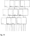
- Figure 14 finally shows a schematic representation to explain the spatial equalization of actuators, both in the vertical direction (ie at right angles to the nozzle plane) and in the horizontal direction (ie parallel to the nozzle plane).
- two rows of actuators are arranged one above the other, parallel to one another and parallel to the row of nozzles.
- the row of actuators on the right comprises two actuators a.1.1 and a.1.2, while the other row of actuators has two actuators b.1.1 and b.1.2 as an example.
- middle actuator level which also has two rows of actuators, each with two actuators a.2.1, a.2.2 or b.2.1 or b.2.2.
- the lower actuator level also contains two rows of actuators, each with two actuators a.3.1, a.3.2 and b.3.1, b.3.2, respectively.
Claims (14)
- Applicateur, plus particulièrement tête d'impression, pour l'application d'un produit de revêtement, plus particulièrement d'une peinture, sur un composant, plus particulièrement sur un composant de carrosserie de véhicule automobile ou une pièce rapportée pour un composant de carrosserie de véhicule automobile, aveca) au moins une rangée de buses (21) avec plusieurs buses (22 - 28 ; 60 ; 78) pour la distribution du produit de revêtement sous la forme d'un jet de produit de revêtement (54 ; 61 ; 77), dans lequel les buses (22 - 28 ; 60 ; 78) sont disposées le long de chaque rangée de buses (21) successivement dans un plan de buse, avec une distance déterminée entre les buses (d) etb) plusieurs actionneurs (a.1.1 - b.3.2) pour le contrôle de la distribution de produit de revêtement par les différentes buses (22 - 28 ; 60 ; 78),b1) dans lequel les actionneurs (a.1.1 - b.3.2) présentent chacun une dimension externe (b) le long de la rangée de buses (21) respective,b2) dans lequel les actionneurs (a.1.1 - b.3.2) sont disposés dans plusieurs plans d'actionneurs, dans lequel les différents plans d'actionneur s'étendent parallèlement au plan de buses avec des distances différentes par rapport au plan de buses,c) dans lequel la distance entre les buses (d) entre les buses adjacentes (22 - 28 ; 60 ; 78) de chaque rangée de buses (21) est inférieure à la dimension externe (b) des différents actionneurs (a.1.1 - b.3.2) le long de la rangée de buses (21) respective,d) dans lequel les actionneurs (a.1.1 - b.3.2) sont disposés dans les différents plans d'actionneurs respectivement dans plusieurs rangées d'actionneurs parallèlement à la rangée de buses (21) respective, plus particulièrement des deux côtés de la rangée de buses (21) respective,
caractérisé en ce quee) les actionneurs superposés verticalement présentent entre eux un décalage horizontal qui est globalement aussi grand que la distance entre les buses (d) entre les buses adjacentes dans la rangée de buses ou correspond à un multiple entier de la distance entre les buses. - Applicateur selon la revendication 1, caractérisé en ce quea) l'applicateur comprend plusieurs soupapes de commande (31 - 34, 39 - 41) pour le contrôle de la distribution du produit de revêtement par les buses (2 - 4), dans lequel les soupapes de commande (31 - 34, 39 - 41) sont contrôlées par les actionneurs (a.1.1 - b.3.2),b) les soupapes de commande (31 - 34, 39 - 41) sont séparées physiquement respectivement par la buse (22 - 28) respective et sont reliées respectivement par l'intermédiaire d'un canal d'écoulement (45 - 51) avec la buse (22 - 28) correspondante, afin de permettre une correction spatiale des buses (22- 28) d'une part et des soupapes de commande d'autre part etc) les soupapes de commande (31 - 34, 39 - 41) sont disposées avec leur point d'arrêt décalé latéralement par rapport à la rangée de buses (21) respective, afin de pouvoir réduire la distance entre les buses (d).
- Applicateur selon la revendication 2, caractérisé en ce quea) les soupapes de commande (31 - 34, 39 - 41) sont disposées des deux côtés de la rangée de buses (21) respective dans deux rangées de soupapes (29, 30) opposées par rapport à la rangée de buses (21) respective etb) les buses (22 - 28) le long de la rangée de buses (21) respective sont reliées alternativement par l'intermédiaire des canaux d'écoulement (45 - 51) avec des soupapes de commande (31 - 34, 39 - 41) des rangées de soupapes (29, 30) opposées.
- Applicateur selon la revendication 2, caractérisé en ce quea) les canaux d'écoulement (80 - 84) partent, à partir de la rangée de buses respective, dans un plan de correction perpendiculaire à la rangée de buses respective, dans plus de deux directions différentes et/oub) les différentes directions des canaux d'écoulement (80 - 84) dans le plan de correction forment respectivement un angle de 20° - 70°, 30° - 60°, 40° - 50° ou de 45° etc) les buses (78) le long de la rangée de buses respective sont reliées alternativement avec un des différents canaux d'écoulement (80 - 84).
- Applicateur selon l'une des revendications précédentes,
caractérisé en ce quea) les différents plans d'actionneurs s'étendent parallèlement au plan de buse etb) dans les différents plans d'actionneurs, sont disposées respectivement deux rangées d'actionneurs des deux côtés de la rangée de buses respective, dans lequel les rangées d'actionneurs contiennent respectivement plusieurs actionneurs (a.1.1 - b.3.2),c) les actionneurs dans les rangées d'actionneurs sont disposés de manière globalement équidistante. - Applicateur selon l'une des revendications 2 à 5, lorsqu'elle est dépendante de la revendication 2, caractérisé en ce quea) les distances entre les soupapes de commandes les buses correspondantes sont partiellement différentes, de façon à ce que les canaux d'écoulement (57, 58) enjambent partiellement des distances différentes etb) les canaux d'écoulement (57, 58) comprennent, pour la compensation des différentes distances, des moyens de compensation de pression (59), dans lequel les moyens de compensation de pression (59) compensent au moins partiellement les différentes pertes de pression le long des canaux d'écoulement (57, 58) de différentes longueurs etc) les moyens de compensation de pression (59) présentent ce qui suit, plus particulièrement au niveau des canaux d'écoulement avec les distances les plus petites entre la buse et le siège de la soupape :c1) une extension en zigzag,c2) une extension de canal en zigzag,c3) une extension de canal en spirale et/ouc4) un rétrécissement de canal.
- Applicateur selon l'une des revendications 2 à 6, lorsqu'elle est dépendante de la revendication 2, caractérisé en ce quea) les différentes soupapes de commande comprennent chacune un siège de soupape (31 - 34, 39 - 41 ; 64) qui peut être fermé ou libéré etb) les différents sièges de soupapes (31 - 34, 39 - 41 ; 64) présentent chacun un diamètre intérieur de 50 µm à 1500 µm et/ouc) un élément de soupape flexible (67), plus particulièrement une membrane de soupape (67), est prévu, dans lequel cet élément de soupape (67) libère ou ferme le siège de soupape (64) en fonction de sa flexion etd) pour la flexion de l'élément de soupape (67)d1) un poussoir coulissant (6) est prévu, qui, dans une position de fermeture, comprime l'élément de soupape (67) contre le siège de soupape (64) et étanchéifie donc celui-ci oud2) une chambre de pression (72) est prévue, dans lequel la chambre de pression (72) sollicite l'élément de soupape (67) avec une pression réglable afin soit de comprimer l'élément de soupape (67) contre le siège de soupape (64) et donc d'étanchéifier celui-ci soit de libérer le siège de soupape (64).
- Applicateur selon la revendication 7, caractérisé en ce quea) un pointeau de soupape coulissant (73) est prévu, dans lequel le pointeau de soupape (73) libère ou ferme le siège de soupape (64) en fonction de sa position etb) le pointeau de soupape (73) est traversé par un élément d'étanchéité (67), plus particulièrement par une membrane d'étanchéité (67), dans lequel l'élément d'étanchéité (67) sépare un espace d'actionneur d'un espace d'alimentation rempli de produit de revêtement et empêche ainsi que les actionneurs dans l'espace d'actionneur soient contaminés par le produit de revêtement etc) le pointeau de soupape (73) comprend, au niveau de sa pointe, un élément d'étanchéité (74) séparé,d) le pointeau de soupape (73) est coulissé respectivement par un des actionneurs (a.1.1 - b.3.2), plus particulièrement pard1) un actionneur électromagnétique,d2) un actionneur piézoélectrique,d3) un actionneur pneumatique,e) les actionneurs (a.1.1 - b.3.2)e1) sont respectivement à simple action et déplacent activement le pointeau de soupape (73) ou le poussoir (69) dans une seule direction, le pointeau de soupape (73) ou le poussoir (69) étant en revanche déplacés dans une direction opposée par un ressort de rappel (71) oue2) sont respectivement à double action et déplacent activement le pointeau de soupape (73) ou le poussoir (69) dans les deux directions.
- Applicateur selon l'une des revendications 2 à 8, lorsqu'elle est dépendante de la revendication 2, caractérisé en ce que les soupapes de commande sont disposées à l'extérieur de l'applicateur et sont reliées avec l'applicateur par une conduite de fluide (75), plus particulièrement un tuyau (75).
- Applicateur selon l'une des revendications 2 à 9, lorsqu'elle est dépendante de la revendication 2, caractérisé en ce quea) les canaux d'écoulement (45 - 51 ; 63 ; 80 - 84) sont alimentés en produit de revêtement à partir d'un canal d'alimentation (66, 53) etb) le canal d'alimentation (66, 53) présente une hauteur de canal de 100 µm - 2000 µm etc) le canal d'alimentation (66, 53) présente une largeur de canal de 1 mm - 5 mm etd) le canal d'alimentation (66, 53) présente une longueur de canal de 1 mm - 100 mm.
- Applicateur selon l'une des revendications 7 à 10, lorsqu'elle est dépendante de la revendication 7, caractérisé en ce quea) les sièges de soupapes adjacents (31 - 34, 39 - 41 ; 64) des soupapes de commande sont disposés parallèlement à la rangée de buses (21) respective à une première distance (a),b) les buses adjacentes (22 - 28 ; 60 ; 78) sont disposées le long de la rangée de buses (21) respective à une deuxième distance (d) etc) la première distance (a) entre les sièges de soupapes adjacents représente au moins le double de la deuxième distance d) entre les buses adjacentes (22 - 28 ; 60 ; 78).
- Applicateur selon l'une des revendications 2 à 11, lorsqu'elle est dépendante de la revendication 2, caractérisé en ce que
le canal d'écoulement (45 - 51 ; 63 ; 80 - 84) s'étend dans un substrat (65) qui est constitué d'un matériau qui est inerte par rapport au produit de revêtement, plus particulièrement d'un des matériaux suivants :a) acier inoxydable,b) matière plastique, plus particulièrementb1) polyétheréthercétone (PEEK),b2) polyéthercétone (PEKK),b3) polyoxyméthylène (POM),b4) polyméthylméthacrylate (PMMA),b5) polyamide (PA),b6) polyéthylène (PE),b7) polypropylène (PP),b8) polystyrène (PS),b9) polycarbonate (PC),b10) copolymère de cyclo-oléfine, plus particulièrement Topas® , Zeonor® ou Zeonex®,c) siliciumd) verre. - Applicateur selon l'une des revendications 2 à 12, lorsqu'elle est dépendante de la revendication 2, caractérisé en ce quea) les canaux d'écoulement (45 - 51 ; 63 ; 80 - 84) forment, au moins sur une partie de leur longueur, un angle (a) de 0° - 90°, 20° - 85°, 45° - 80° avec le jet de produit de revêtement (54 ; 61 ; 77) et/oub) les canaux d'écoulement (45 - 51 ; 63 ; 80 - 84) s'étendent, au moins sur une partie de leur longueur, avec un angle (a) de 0° - 90° ou de 45° - 90° ou transversalement, plus particulièrement perpendiculairement par rapport à la rangée de buses (21) respective et/ouc) les canaux d'écoulement (45 - 51 ; 63 ; 80 - 84) s'étendent, au moins sur une partie de leur longueur, avec un angle (a) de 0° - 90° ou de 45° - 90°, plus particulièrement perpendiculairement, par rapport au jet de produit de revêtement (54 ; 61 ; 77) et de manière orthogonale par rapport à la rangée de buses (21) respective et/oud) les canaux d'écoulement (45 - 51 ; 63 ; 80 - 84) présentent chacun une section transversale de canal avec une hauteur de canal de 50 µm - 1000 µm ou de 100 µm - 500 µm et/oue) les canaux d'écoulement présentent chacun une section transversale de canal avec une largeur de canal de 50 µm - 1000 µm ou de 100 µm - 500 µm et/ouf) les canaux d'écoulement (45 - 51 ; 63 ; 80 - 84) présentent chacun une longueur de canal de 0,1 mm - 50 mm ou de 0,5 mm - 25 mm et/oug) les canaux d'écoulement (45 - 51 ; 63 ; 80 - 84) présentent une section transversale de canal ronde, plus particulièrement avec un diamètre de canal de 50 µm - 1000 µm et/ouh) les canaux d'écoulement (45 - 51 ; 63 ; 80 - 84) présentent chacun, entre le point d'arrêt des soupapes de commande et les buses (22 - 28 ; 60 ; 78), un petit volume inférieur à 1 mL, 0,5 mL, 0,1 mL, 0,01 ml, 0,001 ml et/oui) la distance entre les buses (d) le long de la rangée de buses (21) respective est inférieure à 3 mm, 2 mm, 1 mm ou 0,5 mm et/ouj) les soupapes de commande sont disposées à une distance d'au moins 1 mm, 2 mm, 3 mm, 4 mm, 5 mm ou 6 mm de la rangée de buses (21) respective et/ouk) les buses (22 - 28 ; 60 ; 78) sont disposées de manière équidistante le long de la rangée de buses (21) respective.
- Robot de revêtement, plus particulièrement robot de peinture, avec un applicateur selon l'une des revendications précédentes.
Applications Claiming Priority (2)
| Application Number | Priority Date | Filing Date | Title |
|---|---|---|---|
| DE102017122495.5A DE102017122495A1 (de) | 2017-09-27 | 2017-09-27 | Applikator mit einem geringen Düsenabstand |
| PCT/EP2018/076219 WO2019063668A1 (fr) | 2017-09-27 | 2018-09-27 | Applicateur présentant une faible distance entre les buses |
Publications (2)
| Publication Number | Publication Date |
|---|---|
| EP3687701A1 EP3687701A1 (fr) | 2020-08-05 |
| EP3687701B1 true EP3687701B1 (fr) | 2021-08-04 |
Family
ID=63794443
Family Applications (1)
| Application Number | Title | Priority Date | Filing Date |
|---|---|---|---|
| EP18782913.0A Active EP3687701B1 (fr) | 2017-09-27 | 2018-09-27 | Applicateur à interval de buses réduit |
Country Status (10)
| Country | Link |
|---|---|
| US (1) | US11511291B2 (fr) |
| EP (1) | EP3687701B1 (fr) |
| JP (1) | JP2020535010A (fr) |
| KR (1) | KR102588319B1 (fr) |
| CN (1) | CN111526948B (fr) |
| DE (1) | DE102017122495A1 (fr) |
| ES (1) | ES2895476T3 (fr) |
| HU (1) | HUE056132T2 (fr) |
| MX (1) | MX2020003327A (fr) |
| WO (1) | WO2019063668A1 (fr) |
Families Citing this family (2)
| Publication number | Priority date | Publication date | Assignee | Title |
|---|---|---|---|---|
| DE102017122488A1 (de) * | 2017-09-27 | 2019-03-28 | Dürr Systems Ag | Applikator mit einer Dichtungsmembran |
| CN113102125A (zh) * | 2021-03-24 | 2021-07-13 | 北京霍里思特科技有限公司 | 喷射头、喷射系统、矿产分选机 |
Family Cites Families (47)
| Publication number | Priority date | Publication date | Assignee | Title |
|---|---|---|---|---|
| US2296079A (en) | 1939-01-23 | 1942-09-15 | Gen Mills Inc | Gluing head |
| US4128345A (en) | 1975-03-28 | 1978-12-05 | Universal Technology, Inc. | Fluid impulse matrix printer |
| US4157149A (en) * | 1977-10-31 | 1979-06-05 | Moen Lenard E | Multiple nozzle fluid dispenser for complex fluid delivery patterns |
| DE3302617A1 (de) | 1983-01-27 | 1984-08-02 | Cyklop International Emil Hoffmann KG, 5000 Köln | Farbspritzkopf |
| DE3506393A1 (de) | 1985-02-23 | 1986-08-28 | Windmöller & Hölscher, 4540 Lengerich | Leimauftragsvorrichtung |
| DE3624844A1 (de) | 1986-07-23 | 1988-01-28 | Josef Schucker | Temperiergeraet fuer fluessige klebstoffe |
| DE3634137A1 (de) * | 1986-10-07 | 1988-04-21 | Willett Int Ltd | Verfahren und vorrichtung zum diskontinuierlichen aufbringen eines aushaertenden stoffes auf einen gegenstand |
| GB8700203D0 (en) | 1987-01-07 | 1987-02-11 | Domino Printing Sciences Plc | Ink jet printing head |
| US5022629A (en) | 1988-01-04 | 1991-06-11 | Interface, Inc. | Valve construction |
| US5066216A (en) | 1989-09-22 | 1991-11-19 | Binney & Smith Inc. | Apparatus for injection of viscous material |
| US5087930A (en) * | 1989-11-01 | 1992-02-11 | Tektronix, Inc. | Drop-on-demand ink jet print head |
| US5145689A (en) | 1990-10-17 | 1992-09-08 | Exxon Chemical Patents Inc. | Meltblowing die |
| JPH05293959A (ja) | 1992-04-22 | 1993-11-09 | Citizen Watch Co Ltd | インクジェットヘッド |
| US5769947A (en) | 1994-10-22 | 1998-06-23 | Itw Dynatech Gmbh Klebetechnik | Applicator for adhesive and corresponding nozzle plate |
| US5800614A (en) | 1996-09-24 | 1998-09-01 | Foust; Paul William | Adhesive applier for screen printing machine |
| US7628468B2 (en) | 1997-07-15 | 2009-12-08 | Silverbrook Research Pty Ltd | Nozzle with reciprocating plunger |
| JP2001146010A (ja) | 1999-11-18 | 2001-05-29 | Nec Corp | インクジェット記録ヘッド |
| US7152962B1 (en) | 2000-05-24 | 2006-12-26 | Silverbrook Research Pty Ltd | Ink jet printhead having a moving nozzle with an externally arranged actuator |
| US20030131791A1 (en) * | 2000-11-21 | 2003-07-17 | Schultz Carl L. | Multiple orifice applicator system and method of using same |
| US6776360B2 (en) | 2001-06-26 | 2004-08-17 | Spraying Systems Co. | Spray gun with improved needle shut-off valve sealing arrangement |
| KR100439084B1 (ko) | 2001-11-15 | 2004-07-09 | 주식회사 프로텍 | 업다운 및 회전의 정밀제어가 가능한 고속정량토출형디스펜서 헤드 |
| CN101351273B (zh) | 2005-11-03 | 2011-07-27 | 喷雾系统公司 | 静电式喷雾组件 |
| JP2007320042A (ja) | 2006-05-30 | 2007-12-13 | Mimaki Engineering Co Ltd | 流体吐出装置および流体吐出装置群 |
| ITTV20060124A1 (it) | 2006-07-17 | 2008-01-18 | Hip Mitsu Srl | Struttura di testata di spalmatura, particolarmente di uno o piu' adesivi o miscele di adesivi |
| DE202006016377U1 (de) | 2006-10-20 | 2007-02-01 | Lincoln Gmbh | Schmiermittelverteiler |
| JP5059377B2 (ja) | 2006-11-08 | 2012-10-24 | 株式会社ニレコ | マーキングノズル装置 |
| EP1938911A1 (fr) | 2006-12-27 | 2008-07-02 | VAI Industries (UK) Ltd. | Dispositif et procédé pour refroidissement contrôlé |
| JP4643625B2 (ja) | 2007-09-25 | 2011-03-02 | 株式会社東芝 | 液滴噴射ヘッド |
| US20090107398A1 (en) | 2007-10-31 | 2009-04-30 | Nordson Corporation | Fluid dispensers and methods for dispensing viscous fluids with improved edge definition |
| CN103909743B (zh) * | 2007-12-31 | 2017-01-11 | 埃克阿泰克有限责任公司 | 用于打印三维物品的装置和方法 |
| DE102008053178A1 (de) * | 2008-10-24 | 2010-05-12 | Dürr Systems GmbH | Beschichtungseinrichtung und zugehöriges Beschichtungsverfahren |
| CN101480642B (zh) | 2008-12-30 | 2011-07-27 | 大连华工创新科技有限公司 | 多阀联动喷胶装置 |
| EP2434231B1 (fr) | 2009-05-18 | 2019-06-26 | Mitsubishi Electric Corporation | Dispositif de pompe à chaleur et procédé de commande d'une soupape de régulation |
| CN201415168Y (zh) | 2009-07-16 | 2010-03-03 | 东莞市事通达机电科技有限公司 | 喷漆机械手使用的喷枪 |
| WO2012058373A2 (fr) | 2010-10-27 | 2012-05-03 | Matthews Resources, Inc. | Imprimante à jet par clapet ayant un embout de piston plongeur inerte |
| DE202010013054U1 (de) | 2010-12-03 | 2012-03-05 | Baumer Hhs Gmbh | Vorrichtung zum Auftragen von viskosen Medien |
| WO2016025858A1 (fr) | 2014-08-15 | 2016-02-18 | Bowles Fluidics Corporation | Buse de coupelle fluidique à plusieurs entrées et à plusieurs jets pulvérisés comprenant une zone d'interaction commune et procédé de production de jets pulvérisés |
| CN103826858B (zh) | 2011-07-22 | 2016-08-17 | 杜斯特摄影技术股份公司 | 用于喷墨打印机的打印头 |
| JP2013107256A (ja) | 2011-11-18 | 2013-06-06 | Seiko Epson Corp | 液体噴射ヘッド及び液体噴射装置 |
| WO2013140814A1 (fr) | 2012-03-22 | 2013-09-26 | 株式会社安川電機 | Dispositif d'application de revêtement |
| DE102013208751A1 (de) | 2013-05-13 | 2014-11-13 | Koenig & Bauer Aktiengesellschaft | Druckmaschine |
| CN104324866B (zh) | 2013-07-22 | 2016-05-11 | 泰科电子(上海)有限公司 | 在工件的凹槽中注入密封胶的方法 |
| JP2015096322A (ja) | 2013-10-07 | 2015-05-21 | 株式会社ミマキエンジニアリング | 印刷装置、インクジェットヘッド、及び印刷方法 |
| ES2811824T3 (es) | 2014-06-04 | 2021-03-15 | System Ceramics S P A | Un dispositivo para la impresión por inyección de tinta de fluidos, en particular esmaltes, sobre azulejos |
| DE102014013158A1 (de) * | 2014-09-11 | 2016-03-17 | Burkhard Büstgens | Freistrahl-Einrichtung |
| CN104647903B (zh) * | 2015-02-09 | 2016-07-06 | 清华大学深圳研究生院 | 一种基于微流控芯片的打印喷头装置 |
| EP4306803A3 (fr) | 2017-03-31 | 2024-04-10 | Vaxxas Pty Limited | Dispositif et procédé de revêtement de surfaces |
-
2017
- 2017-09-27 DE DE102017122495.5A patent/DE102017122495A1/de not_active Withdrawn
-
2018
- 2018-09-27 WO PCT/EP2018/076219 patent/WO2019063668A1/fr unknown
- 2018-09-27 US US16/649,236 patent/US11511291B2/en active Active
- 2018-09-27 EP EP18782913.0A patent/EP3687701B1/fr active Active
- 2018-09-27 ES ES18782913T patent/ES2895476T3/es active Active
- 2018-09-27 CN CN201880063177.2A patent/CN111526948B/zh active Active
- 2018-09-27 MX MX2020003327A patent/MX2020003327A/es unknown
- 2018-09-27 JP JP2020518041A patent/JP2020535010A/ja active Pending
- 2018-09-27 KR KR1020207007579A patent/KR102588319B1/ko active IP Right Grant
- 2018-09-27 HU HUE18782913A patent/HUE056132T2/hu unknown
Also Published As
| Publication number | Publication date |
|---|---|
| CN111526948B (zh) | 2022-11-04 |
| ES2895476T3 (es) | 2022-02-21 |
| KR20200060714A (ko) | 2020-06-01 |
| MX2020003327A (es) | 2020-07-28 |
| US11511291B2 (en) | 2022-11-29 |
| WO2019063668A1 (fr) | 2019-04-04 |
| KR102588319B1 (ko) | 2023-10-12 |
| JP2020535010A (ja) | 2020-12-03 |
| EP3687701A1 (fr) | 2020-08-05 |
| CN111526948A (zh) | 2020-08-11 |
| US20200246813A1 (en) | 2020-08-06 |
| HUE056132T2 (hu) | 2022-01-28 |
| DE102017122495A1 (de) | 2019-03-28 |
Similar Documents
| Publication | Publication Date | Title |
|---|---|---|
| EP2118542B1 (fr) | Microsoupape | |
| EP3698880B1 (fr) | Tête d'impression pour appliquer un moyen de revêtement | |
| EP3535063B1 (fr) | Tete d'impression pour appliquer un produit de revêtement sur une piece | |
| DE102014013158A1 (de) | Freistrahl-Einrichtung | |
| EP3687701B1 (fr) | Applicateur à interval de buses réduit | |
| EP3687699B1 (fr) | Applicateur muni d'une membrane étanche | |
| EP3902635A1 (fr) | Soupape de dosage à jet | |
| DE102013202531B3 (de) | Spender zum Austrag von Flüssigkeiten | |
| DE102012100836B3 (de) | Kapillardispenser | |
| DE102017126307A1 (de) | Dosiervorrichtung sowie Verfahren zum Dosieren von flüssigen Medien | |
| WO1999058860A1 (fr) | Microsoupape | |
| DE102012001775B3 (de) | Piezoventil | |
| EP3687700B1 (fr) | Applicateur à interval de buses réduit | |
| EP3896283B1 (fr) | Tête d'impression pourvue d'unité de commande micropneumatique | |
| EP3362671B1 (fr) | Injecteur piézoélectrique pour l'injection de carburant | |
| EP2945754B1 (fr) | Dispositif de dosage | |
| DE102012006608A1 (de) | Antriebsvorrichtung | |
| DE10243997B4 (de) | Mikroventil in Mehrschichtaufbau | |
| DE102021109850A1 (de) | Dosiermodul | |
| DE102022108717A1 (de) | Extruderventil für einen extrusionsbasierten, thermoplastischen Materialaustrag sowie Verfahren zum extrusionsbasierten, thermoplastischen Materialaustrag | |
| DE102013101637A1 (de) | Auftragskopf für viskose Medien | |
| DE10252793A1 (de) | Elektrostatischer Antrieb und damit ausgestattetes Ventil | |
| DE102013020312A1 (de) | Ventilanordnung | |
| DE102015102851A1 (de) | Ventil und Spendervorrichtung |
Legal Events
| Date | Code | Title | Description |
|---|---|---|---|
| STAA | Information on the status of an ep patent application or granted ep patent |
Free format text: STATUS: UNKNOWN |
|
| STAA | Information on the status of an ep patent application or granted ep patent |
Free format text: STATUS: THE INTERNATIONAL PUBLICATION HAS BEEN MADE |
|
| PUAI | Public reference made under article 153(3) epc to a published international application that has entered the european phase |
Free format text: ORIGINAL CODE: 0009012 |
|
| STAA | Information on the status of an ep patent application or granted ep patent |
Free format text: STATUS: REQUEST FOR EXAMINATION WAS MADE |
|
| 17P | Request for examination filed |
Effective date: 20200207 |
|
| AK | Designated contracting states |
Kind code of ref document: A1 Designated state(s): AL AT BE BG CH CY CZ DE DK EE ES FI FR GB GR HR HU IE IS IT LI LT LU LV MC MK MT NL NO PL PT RO RS SE SI SK SM TR |
|
| AX | Request for extension of the european patent |
Extension state: BA ME |
|
| TPAC | Observations filed by third parties |
Free format text: ORIGINAL CODE: EPIDOSNTIPA |
|
| DAV | Request for validation of the european patent (deleted) | ||
| DAX | Request for extension of the european patent (deleted) | ||
| RIC1 | Information provided on ipc code assigned before grant |
Ipc: B05B 1/30 20060101AFI20210324BHEP Ipc: B05B 1/14 20060101ALI20210324BHEP Ipc: B41J 2/175 20060101ALI20210324BHEP |
|
| GRAP | Despatch of communication of intention to grant a patent |
Free format text: ORIGINAL CODE: EPIDOSNIGR1 |
|
| STAA | Information on the status of an ep patent application or granted ep patent |
Free format text: STATUS: GRANT OF PATENT IS INTENDED |
|
| INTG | Intention to grant announced |
Effective date: 20210503 |
|
| GRAS | Grant fee paid |
Free format text: ORIGINAL CODE: EPIDOSNIGR3 |
|
| GRAA | (expected) grant |
Free format text: ORIGINAL CODE: 0009210 |
|
| STAA | Information on the status of an ep patent application or granted ep patent |
Free format text: STATUS: THE PATENT HAS BEEN GRANTED |
|
| AK | Designated contracting states |
Kind code of ref document: B1 Designated state(s): AL AT BE BG CH CY CZ DE DK EE ES FI FR GB GR HR HU IE IS IT LI LT LU LV MC MK MT NL NO PL PT RO RS SE SI SK SM TR |
|
| REG | Reference to a national code |
Ref country code: GB Ref legal event code: FG4D Free format text: NOT ENGLISH |
|
| REG | Reference to a national code |
Ref country code: AT Ref legal event code: REF Ref document number: 1416425 Country of ref document: AT Kind code of ref document: T Effective date: 20210815 |
|
| REG | Reference to a national code |
Ref country code: CH Ref legal event code: EP |
|
| REG | Reference to a national code |
Ref country code: DE Ref legal event code: R096 Ref document number: 502018006460 Country of ref document: DE |
|
| REG | Reference to a national code |
Ref country code: IE Ref legal event code: FG4D Free format text: LANGUAGE OF EP DOCUMENT: GERMAN |
|
| REG | Reference to a national code |
Ref country code: LT Ref legal event code: MG9D |
|
| REG | Reference to a national code |
Ref country code: NL Ref legal event code: MP Effective date: 20210804 |
|
| REG | Reference to a national code |
Ref country code: SK Ref legal event code: T3 Ref document number: E 38501 Country of ref document: SK |
|
| REG | Reference to a national code |
Ref country code: HU Ref legal event code: AG4A Ref document number: E056132 Country of ref document: HU |
|
| PG25 | Lapsed in a contracting state [announced via postgrant information from national office to epo] |
Ref country code: SE Free format text: LAPSE BECAUSE OF FAILURE TO SUBMIT A TRANSLATION OF THE DESCRIPTION OR TO PAY THE FEE WITHIN THE PRESCRIBED TIME-LIMIT Effective date: 20210804 Ref country code: RS Free format text: LAPSE BECAUSE OF FAILURE TO SUBMIT A TRANSLATION OF THE DESCRIPTION OR TO PAY THE FEE WITHIN THE PRESCRIBED TIME-LIMIT Effective date: 20210804 Ref country code: HR Free format text: LAPSE BECAUSE OF FAILURE TO SUBMIT A TRANSLATION OF THE DESCRIPTION OR TO PAY THE FEE WITHIN THE PRESCRIBED TIME-LIMIT Effective date: 20210804 Ref country code: FI Free format text: LAPSE BECAUSE OF FAILURE TO SUBMIT A TRANSLATION OF THE DESCRIPTION OR TO PAY THE FEE WITHIN THE PRESCRIBED TIME-LIMIT Effective date: 20210804 Ref country code: BG Free format text: LAPSE BECAUSE OF FAILURE TO SUBMIT A TRANSLATION OF THE DESCRIPTION OR TO PAY THE FEE WITHIN THE PRESCRIBED TIME-LIMIT Effective date: 20211104 Ref country code: LT Free format text: LAPSE BECAUSE OF FAILURE TO SUBMIT A TRANSLATION OF THE DESCRIPTION OR TO PAY THE FEE WITHIN THE PRESCRIBED TIME-LIMIT Effective date: 20210804 Ref country code: NO Free format text: LAPSE BECAUSE OF FAILURE TO SUBMIT A TRANSLATION OF THE DESCRIPTION OR TO PAY THE FEE WITHIN THE PRESCRIBED TIME-LIMIT Effective date: 20211104 Ref country code: PT Free format text: LAPSE BECAUSE OF FAILURE TO SUBMIT A TRANSLATION OF THE DESCRIPTION OR TO PAY THE FEE WITHIN THE PRESCRIBED TIME-LIMIT Effective date: 20211206 |
|
| REG | Reference to a national code |
Ref country code: ES Ref legal event code: FG2A Ref document number: 2895476 Country of ref document: ES Kind code of ref document: T3 Effective date: 20220221 |
|
| PG25 | Lapsed in a contracting state [announced via postgrant information from national office to epo] |
Ref country code: PL Free format text: LAPSE BECAUSE OF FAILURE TO SUBMIT A TRANSLATION OF THE DESCRIPTION OR TO PAY THE FEE WITHIN THE PRESCRIBED TIME-LIMIT Effective date: 20210804 Ref country code: LV Free format text: LAPSE BECAUSE OF FAILURE TO SUBMIT A TRANSLATION OF THE DESCRIPTION OR TO PAY THE FEE WITHIN THE PRESCRIBED TIME-LIMIT Effective date: 20210804 Ref country code: GR Free format text: LAPSE BECAUSE OF FAILURE TO SUBMIT A TRANSLATION OF THE DESCRIPTION OR TO PAY THE FEE WITHIN THE PRESCRIBED TIME-LIMIT Effective date: 20211105 |
|
| PG25 | Lapsed in a contracting state [announced via postgrant information from national office to epo] |
Ref country code: NL Free format text: LAPSE BECAUSE OF FAILURE TO SUBMIT A TRANSLATION OF THE DESCRIPTION OR TO PAY THE FEE WITHIN THE PRESCRIBED TIME-LIMIT Effective date: 20210804 |
|
| PG25 | Lapsed in a contracting state [announced via postgrant information from national office to epo] |
Ref country code: DK Free format text: LAPSE BECAUSE OF FAILURE TO SUBMIT A TRANSLATION OF THE DESCRIPTION OR TO PAY THE FEE WITHIN THE PRESCRIBED TIME-LIMIT Effective date: 20210804 |
|
| REG | Reference to a national code |
Ref country code: CH Ref legal event code: PL |
|
| REG | Reference to a national code |
Ref country code: DE Ref legal event code: R097 Ref document number: 502018006460 Country of ref document: DE |
|
| REG | Reference to a national code |
Ref country code: BE Ref legal event code: MM Effective date: 20210930 |
|
| PG25 | Lapsed in a contracting state [announced via postgrant information from national office to epo] |
Ref country code: SM Free format text: LAPSE BECAUSE OF FAILURE TO SUBMIT A TRANSLATION OF THE DESCRIPTION OR TO PAY THE FEE WITHIN THE PRESCRIBED TIME-LIMIT Effective date: 20210804 Ref country code: RO Free format text: LAPSE BECAUSE OF FAILURE TO SUBMIT A TRANSLATION OF THE DESCRIPTION OR TO PAY THE FEE WITHIN THE PRESCRIBED TIME-LIMIT Effective date: 20210804 Ref country code: MC Free format text: LAPSE BECAUSE OF FAILURE TO SUBMIT A TRANSLATION OF THE DESCRIPTION OR TO PAY THE FEE WITHIN THE PRESCRIBED TIME-LIMIT Effective date: 20210804 Ref country code: EE Free format text: LAPSE BECAUSE OF FAILURE TO SUBMIT A TRANSLATION OF THE DESCRIPTION OR TO PAY THE FEE WITHIN THE PRESCRIBED TIME-LIMIT Effective date: 20210804 Ref country code: AL Free format text: LAPSE BECAUSE OF FAILURE TO SUBMIT A TRANSLATION OF THE DESCRIPTION OR TO PAY THE FEE WITHIN THE PRESCRIBED TIME-LIMIT Effective date: 20210804 |
|
| PLBE | No opposition filed within time limit |
Free format text: ORIGINAL CODE: 0009261 |
|
| STAA | Information on the status of an ep patent application or granted ep patent |
Free format text: STATUS: NO OPPOSITION FILED WITHIN TIME LIMIT |
|
| 26N | No opposition filed |
Effective date: 20220506 |
|
| PG25 | Lapsed in a contracting state [announced via postgrant information from national office to epo] |
Ref country code: IE Free format text: LAPSE BECAUSE OF NON-PAYMENT OF DUE FEES Effective date: 20210927 Ref country code: BE Free format text: LAPSE BECAUSE OF NON-PAYMENT OF DUE FEES Effective date: 20210930 Ref country code: LU Free format text: LAPSE BECAUSE OF NON-PAYMENT OF DUE FEES Effective date: 20210927 |
|
| PG25 | Lapsed in a contracting state [announced via postgrant information from national office to epo] |
Ref country code: SI Free format text: LAPSE BECAUSE OF FAILURE TO SUBMIT A TRANSLATION OF THE DESCRIPTION OR TO PAY THE FEE WITHIN THE PRESCRIBED TIME-LIMIT Effective date: 20210804 Ref country code: LI Free format text: LAPSE BECAUSE OF NON-PAYMENT OF DUE FEES Effective date: 20210930 Ref country code: CH Free format text: LAPSE BECAUSE OF NON-PAYMENT OF DUE FEES Effective date: 20210930 |
|
| P01 | Opt-out of the competence of the unified patent court (upc) registered |
Effective date: 20230512 |
|
| PG25 | Lapsed in a contracting state [announced via postgrant information from national office to epo] |
Ref country code: CY Free format text: LAPSE BECAUSE OF FAILURE TO SUBMIT A TRANSLATION OF THE DESCRIPTION OR TO PAY THE FEE WITHIN THE PRESCRIBED TIME-LIMIT Effective date: 20210804 |
|
| PGFP | Annual fee paid to national office [announced via postgrant information from national office to epo] |
Ref country code: TR Payment date: 20230925 Year of fee payment: 6 Ref country code: IT Payment date: 20230921 Year of fee payment: 6 Ref country code: GB Payment date: 20230920 Year of fee payment: 6 Ref country code: CZ Payment date: 20230919 Year of fee payment: 6 |
|
| PGFP | Annual fee paid to national office [announced via postgrant information from national office to epo] |
Ref country code: SK Payment date: 20230919 Year of fee payment: 6 Ref country code: HU Payment date: 20230922 Year of fee payment: 6 Ref country code: FR Payment date: 20230928 Year of fee payment: 6 Ref country code: DE Payment date: 20230920 Year of fee payment: 6 |
|
| PGFP | Annual fee paid to national office [announced via postgrant information from national office to epo] |
Ref country code: ES Payment date: 20231124 Year of fee payment: 6 |