EP3687701B1 - Applicator with reduced nozzle interval - Google Patents
Applicator with reduced nozzle interval Download PDFInfo
- Publication number
- EP3687701B1 EP3687701B1 EP18782913.0A EP18782913A EP3687701B1 EP 3687701 B1 EP3687701 B1 EP 3687701B1 EP 18782913 A EP18782913 A EP 18782913A EP 3687701 B1 EP3687701 B1 EP 3687701B1
- Authority
- EP
- European Patent Office
- Prior art keywords
- nozzles
- valve
- flow channels
- actuators
- actuator
- Prior art date
- Legal status (The legal status is an assumption and is not a legal conclusion. Google has not performed a legal analysis and makes no representation as to the accuracy of the status listed.)
- Active
Links
- 239000011248 coating agent Substances 0.000 claims description 66
- 239000012528 membrane Substances 0.000 claims description 37
- 238000007789 sealing Methods 0.000 claims description 19
- 239000000758 substrate Substances 0.000 claims description 10
- -1 polyoxymethylene Polymers 0.000 claims description 9
- 229920003229 poly(methyl methacrylate) Polymers 0.000 claims description 6
- 229920002647 polyamide Polymers 0.000 claims description 6
- 229920002530 polyetherether ketone Polymers 0.000 claims description 6
- 229920000573 polyethylene Polymers 0.000 claims description 6
- 229920006324 polyoxymethylene Polymers 0.000 claims description 6
- 229920001155 polypropylene Polymers 0.000 claims description 6
- 238000010422 painting Methods 0.000 claims description 5
- 239000003973 paint Substances 0.000 claims description 4
- 239000004033 plastic Substances 0.000 claims description 4
- 229920003023 plastic Polymers 0.000 claims description 4
- 229920000515 polycarbonate Polymers 0.000 claims description 4
- WKBPZYKAUNRMKP-UHFFFAOYSA-N 1-[2-(2,4-dichlorophenyl)pentyl]1,2,4-triazole Chemical compound C=1C=C(Cl)C=C(Cl)C=1C(CCC)CN1C=NC=N1 WKBPZYKAUNRMKP-UHFFFAOYSA-N 0.000 claims description 3
- 229930040373 Paraformaldehyde Natural products 0.000 claims description 3
- 239000004696 Poly ether ether ketone Substances 0.000 claims description 3
- 239000004952 Polyamide Substances 0.000 claims description 3
- 239000004698 Polyethylene Substances 0.000 claims description 3
- 239000004743 Polypropylene Substances 0.000 claims description 3
- 229920001577 copolymer Polymers 0.000 claims description 3
- 239000000463 material Substances 0.000 claims description 3
- 229920001643 poly(ether ketone) Polymers 0.000 claims description 3
- 229920001652 poly(etherketoneketone) Polymers 0.000 claims description 3
- 239000004926 polymethyl methacrylate Substances 0.000 claims description 3
- 239000004793 Polystyrene Substances 0.000 claims description 2
- 238000000576 coating method Methods 0.000 claims description 2
- 239000012530 fluid Substances 0.000 claims description 2
- 239000011521 glass Substances 0.000 claims description 2
- 239000004417 polycarbonate Substances 0.000 claims description 2
- 239000010703 silicon Substances 0.000 claims description 2
- 229910052710 silicon Inorganic materials 0.000 claims description 2
- 239000010935 stainless steel Substances 0.000 claims description 2
- 229910001220 stainless steel Inorganic materials 0.000 claims description 2
- 230000001419 dependent effect Effects 0.000 claims 7
- 239000011031 topaz Substances 0.000 claims 1
- 229910052853 topaz Inorganic materials 0.000 claims 1
- 238000000034 method Methods 0.000 description 7
- 230000004048 modification Effects 0.000 description 4
- 238000012986 modification Methods 0.000 description 4
- 230000008569 process Effects 0.000 description 4
- 230000001427 coherent effect Effects 0.000 description 3
- 239000000853 adhesive Substances 0.000 description 2
- 230000001070 adhesive effect Effects 0.000 description 2
- 238000006073 displacement reaction Methods 0.000 description 2
- 238000004519 manufacturing process Methods 0.000 description 2
- 229920002223 polystyrene Polymers 0.000 description 2
- 230000009467 reduction Effects 0.000 description 2
- 239000007921 spray Substances 0.000 description 2
- 238000010146 3D printing Methods 0.000 description 1
- 241000237369 Helix pomatia Species 0.000 description 1
- 230000009471 action Effects 0.000 description 1
- 230000004913 activation Effects 0.000 description 1
- 238000004026 adhesive bonding Methods 0.000 description 1
- 230000008901 benefit Effects 0.000 description 1
- 238000011161 development Methods 0.000 description 1
- 230000018109 developmental process Effects 0.000 description 1
- 238000009792 diffusion process Methods 0.000 description 1
- 230000000694 effects Effects 0.000 description 1
- 238000005530 etching Methods 0.000 description 1
- 238000001746 injection moulding Methods 0.000 description 1
- 238000009434 installation Methods 0.000 description 1
- 239000011810 insulating material Substances 0.000 description 1
- 239000004922 lacquer Substances 0.000 description 1
- 238000000608 laser ablation Methods 0.000 description 1
- 238000003698 laser cutting Methods 0.000 description 1
- 238000001459 lithography Methods 0.000 description 1
- 238000002844 melting Methods 0.000 description 1
- 230000008018 melting Effects 0.000 description 1
- 238000012856 packing Methods 0.000 description 1
- 230000036316 preload Effects 0.000 description 1
- 238000012545 processing Methods 0.000 description 1
- 230000004044 response Effects 0.000 description 1
- 239000003566 sealing material Substances 0.000 description 1
- 238000000110 selective laser sintering Methods 0.000 description 1
- 238000000926 separation method Methods 0.000 description 1
- 238000002174 soft lithography Methods 0.000 description 1
- 239000000243 solution Substances 0.000 description 1
- 238000003466 welding Methods 0.000 description 1
Images


Classifications
-
- B—PERFORMING OPERATIONS; TRANSPORTING
- B05—SPRAYING OR ATOMISING IN GENERAL; APPLYING FLUENT MATERIALS TO SURFACES, IN GENERAL
- B05B—SPRAYING APPARATUS; ATOMISING APPARATUS; NOZZLES
- B05B1/00—Nozzles, spray heads or other outlets, with or without auxiliary devices such as valves, heating means
- B05B1/30—Nozzles, spray heads or other outlets, with or without auxiliary devices such as valves, heating means designed to control volume of flow, e.g. with adjustable passages
- B05B1/3033—Nozzles, spray heads or other outlets, with or without auxiliary devices such as valves, heating means designed to control volume of flow, e.g. with adjustable passages the control being effected by relative coaxial longitudinal movement of the controlling element and the spray head
- B05B1/304—Nozzles, spray heads or other outlets, with or without auxiliary devices such as valves, heating means designed to control volume of flow, e.g. with adjustable passages the control being effected by relative coaxial longitudinal movement of the controlling element and the spray head the controlling element being a lift valve
- B05B1/3046—Nozzles, spray heads or other outlets, with or without auxiliary devices such as valves, heating means designed to control volume of flow, e.g. with adjustable passages the control being effected by relative coaxial longitudinal movement of the controlling element and the spray head the controlling element being a lift valve the valve element, e.g. a needle, co-operating with a valve seat located downstream of the valve element and its actuating means, generally in the proximity of the outlet orifice
- B05B1/3053—Nozzles, spray heads or other outlets, with or without auxiliary devices such as valves, heating means designed to control volume of flow, e.g. with adjustable passages the control being effected by relative coaxial longitudinal movement of the controlling element and the spray head the controlling element being a lift valve the valve element, e.g. a needle, co-operating with a valve seat located downstream of the valve element and its actuating means, generally in the proximity of the outlet orifice the actuating means being a solenoid
-
- B—PERFORMING OPERATIONS; TRANSPORTING
- B05—SPRAYING OR ATOMISING IN GENERAL; APPLYING FLUENT MATERIALS TO SURFACES, IN GENERAL
- B05B—SPRAYING APPARATUS; ATOMISING APPARATUS; NOZZLES
- B05B1/00—Nozzles, spray heads or other outlets, with or without auxiliary devices such as valves, heating means
- B05B1/30—Nozzles, spray heads or other outlets, with or without auxiliary devices such as valves, heating means designed to control volume of flow, e.g. with adjustable passages
- B05B1/3033—Nozzles, spray heads or other outlets, with or without auxiliary devices such as valves, heating means designed to control volume of flow, e.g. with adjustable passages the control being effected by relative coaxial longitudinal movement of the controlling element and the spray head
- B05B1/304—Nozzles, spray heads or other outlets, with or without auxiliary devices such as valves, heating means designed to control volume of flow, e.g. with adjustable passages the control being effected by relative coaxial longitudinal movement of the controlling element and the spray head the controlling element being a lift valve
- B05B1/3046—Nozzles, spray heads or other outlets, with or without auxiliary devices such as valves, heating means designed to control volume of flow, e.g. with adjustable passages the control being effected by relative coaxial longitudinal movement of the controlling element and the spray head the controlling element being a lift valve the valve element, e.g. a needle, co-operating with a valve seat located downstream of the valve element and its actuating means, generally in the proximity of the outlet orifice
-
- B—PERFORMING OPERATIONS; TRANSPORTING
- B05—SPRAYING OR ATOMISING IN GENERAL; APPLYING FLUENT MATERIALS TO SURFACES, IN GENERAL
- B05B—SPRAYING APPARATUS; ATOMISING APPARATUS; NOZZLES
- B05B1/00—Nozzles, spray heads or other outlets, with or without auxiliary devices such as valves, heating means
- B05B1/14—Nozzles, spray heads or other outlets, with or without auxiliary devices such as valves, heating means with multiple outlet openings; with strainers in or outside the outlet opening
-
- B—PERFORMING OPERATIONS; TRANSPORTING
- B41—PRINTING; LINING MACHINES; TYPEWRITERS; STAMPS
- B41J—TYPEWRITERS; SELECTIVE PRINTING MECHANISMS, i.e. MECHANISMS PRINTING OTHERWISE THAN FROM A FORME; CORRECTION OF TYPOGRAPHICAL ERRORS
- B41J2/00—Typewriters or selective printing mechanisms characterised by the printing or marking process for which they are designed
- B41J2/005—Typewriters or selective printing mechanisms characterised by the printing or marking process for which they are designed characterised by bringing liquid or particles selectively into contact with a printing material
- B41J2/01—Ink jet
- B41J2/015—Ink jet characterised by the jet generation process
- B41J2/04—Ink jet characterised by the jet generation process generating single droplets or particles on demand
- B41J2/045—Ink jet characterised by the jet generation process generating single droplets or particles on demand by pressure, e.g. electromechanical transducers
- B41J2/04501—Control methods or devices therefor, e.g. driver circuits, control circuits
- B41J2/04581—Control methods or devices therefor, e.g. driver circuits, control circuits controlling heads based on piezoelectric elements
-
- B—PERFORMING OPERATIONS; TRANSPORTING
- B41—PRINTING; LINING MACHINES; TYPEWRITERS; STAMPS
- B41J—TYPEWRITERS; SELECTIVE PRINTING MECHANISMS, i.e. MECHANISMS PRINTING OTHERWISE THAN FROM A FORME; CORRECTION OF TYPOGRAPHICAL ERRORS
- B41J2/00—Typewriters or selective printing mechanisms characterised by the printing or marking process for which they are designed
- B41J2/005—Typewriters or selective printing mechanisms characterised by the printing or marking process for which they are designed characterised by bringing liquid or particles selectively into contact with a printing material
- B41J2/01—Ink jet
- B41J2/135—Nozzles
- B41J2/14—Structure thereof only for on-demand ink jet heads
- B41J2/14201—Structure of print heads with piezoelectric elements
-
- B—PERFORMING OPERATIONS; TRANSPORTING
- B41—PRINTING; LINING MACHINES; TYPEWRITERS; STAMPS
- B41J—TYPEWRITERS; SELECTIVE PRINTING MECHANISMS, i.e. MECHANISMS PRINTING OTHERWISE THAN FROM A FORME; CORRECTION OF TYPOGRAPHICAL ERRORS
- B41J2/00—Typewriters or selective printing mechanisms characterised by the printing or marking process for which they are designed
- B41J2/005—Typewriters or selective printing mechanisms characterised by the printing or marking process for which they are designed characterised by bringing liquid or particles selectively into contact with a printing material
- B41J2/01—Ink jet
- B41J2/135—Nozzles
- B41J2/16—Production of nozzles
- B41J2/1621—Manufacturing processes
-
- B—PERFORMING OPERATIONS; TRANSPORTING
- B41—PRINTING; LINING MACHINES; TYPEWRITERS; STAMPS
- B41J—TYPEWRITERS; SELECTIVE PRINTING MECHANISMS, i.e. MECHANISMS PRINTING OTHERWISE THAN FROM A FORME; CORRECTION OF TYPOGRAPHICAL ERRORS
- B41J2/00—Typewriters or selective printing mechanisms characterised by the printing or marking process for which they are designed
- B41J2/005—Typewriters or selective printing mechanisms characterised by the printing or marking process for which they are designed characterised by bringing liquid or particles selectively into contact with a printing material
- B41J2/01—Ink jet
- B41J2/17—Ink jet characterised by ink handling
- B41J2/175—Ink supply systems ; Circuit parts therefor
- B41J2/17596—Ink pumps, ink valves
-
- C—CHEMISTRY; METALLURGY
- C09—DYES; PAINTS; POLISHES; NATURAL RESINS; ADHESIVES; COMPOSITIONS NOT OTHERWISE PROVIDED FOR; APPLICATIONS OF MATERIALS NOT OTHERWISE PROVIDED FOR
- C09K—MATERIALS FOR MISCELLANEOUS APPLICATIONS, NOT PROVIDED FOR ELSEWHERE
- C09K3/00—Materials not provided for elsewhere
- C09K3/10—Materials in mouldable or extrudable form for sealing or packing joints or covers
-
- B—PERFORMING OPERATIONS; TRANSPORTING
- B41—PRINTING; LINING MACHINES; TYPEWRITERS; STAMPS
- B41J—TYPEWRITERS; SELECTIVE PRINTING MECHANISMS, i.e. MECHANISMS PRINTING OTHERWISE THAN FROM A FORME; CORRECTION OF TYPOGRAPHICAL ERRORS
- B41J2/00—Typewriters or selective printing mechanisms characterised by the printing or marking process for which they are designed
- B41J2/005—Typewriters or selective printing mechanisms characterised by the printing or marking process for which they are designed characterised by bringing liquid or particles selectively into contact with a printing material
- B41J2/01—Ink jet
- B41J2/015—Ink jet characterised by the jet generation process
- B41J2/04—Ink jet characterised by the jet generation process generating single droplets or particles on demand
- B41J2002/041—Electromagnetic transducer
-
- B—PERFORMING OPERATIONS; TRANSPORTING
- B41—PRINTING; LINING MACHINES; TYPEWRITERS; STAMPS
- B41J—TYPEWRITERS; SELECTIVE PRINTING MECHANISMS, i.e. MECHANISMS PRINTING OTHERWISE THAN FROM A FORME; CORRECTION OF TYPOGRAPHICAL ERRORS
- B41J2/00—Typewriters or selective printing mechanisms characterised by the printing or marking process for which they are designed
- B41J2/005—Typewriters or selective printing mechanisms characterised by the printing or marking process for which they are designed characterised by bringing liquid or particles selectively into contact with a printing material
- B41J2/01—Ink jet
- B41J2/135—Nozzles
- B41J2/14—Structure thereof only for on-demand ink jet heads
- B41J2002/14475—Structure thereof only for on-demand ink jet heads characterised by nozzle shapes or number of orifices per chamber
-
- B—PERFORMING OPERATIONS; TRANSPORTING
- B41—PRINTING; LINING MACHINES; TYPEWRITERS; STAMPS
- B41J—TYPEWRITERS; SELECTIVE PRINTING MECHANISMS, i.e. MECHANISMS PRINTING OTHERWISE THAN FROM A FORME; CORRECTION OF TYPOGRAPHICAL ERRORS
- B41J2202/00—Embodiments of or processes related to ink-jet or thermal heads
- B41J2202/01—Embodiments of or processes related to ink-jet heads
- B41J2202/05—Heads having a valve
Definitions
- the invention relates to an applicator (e.g. print head) for applying a coating agent (e.g. paint) to a component (e.g. motor vehicle body component or add-on part for a motor vehicle body component).
- a coating agent e.g. paint
- a component e.g. motor vehicle body component or add-on part for a motor vehicle body component.
- drop-on-demand print heads which emit a jet of droplets or a continuous jet of coating agent and whose operating principle is based on the use of electromagnetic valves.
- a magnetically driven armature is slidably guided in a coil.
- the displaceable armature can directly form a valve needle or act indirectly on a separate valve needle which, depending on its position, either closes a valve seat or releases it for a coating agent release.
- the nozzles for dispensing the coating agent and the associated electromagnetic actuators are here arranged one behind the other along a row of nozzles.
- Such printheads are also used in WO 2012/058373 A2 described.
- These known print heads also work with valve pistons which are moved by electromagnetic actuators, the valve pistons running in an inner guide tube (inner tube tube) in the coil.
- the problem with the known drop-on-demand print heads is the nozzle spacing between the adjacent nozzles, as follows with reference to FIG Figures 1 to 4 is explained.
- the known drop-on-demand print heads usually have a nozzle plate 1 with numerous nozzles 2-4, which are arranged in the nozzle plate 1 along a linear row 5 of nozzles.
- the individual nozzles 2-4 can each emit a jet of coating agent onto the surface of a component 6, as in FIG Figures 1 and 2 is indicated by arrows.
- the control of the coating agent delivery through the nozzles 2-4 is carried out individually by actuators 7-9, which work electromagnetically and each have a valve needle 10-12 in the direction of the double arrow in FIG Figure 3 move.
- valve needle 11 is shown in FIG Figure 3 shown in a lowered position in which the valve needle 11 closes the associated nozzle 3 for a coating agent delivery.
- the valve needles 10 and 12, however, are in Figure 3 in a raised position shown, in which the two valve needles 10, 12 release the associated nozzles 2, 4 for a coating agent delivery.
- a sealing membrane 13 which fluidically separates a coating agent-filled nozzle chamber 14 from an actuator chamber 15 in the print head.
- the sealing membrane 13 prevents the coating agent from the nozzle space 14 from contaminating the actuators 7 - 9 in the actuator space 15.
- the sealing membrane 13 is suspended in a membrane decoupling 16, the membrane decoupling 16 preventing a displacement of one of the valve needles 10-12 from leading to a corresponding displacement of the adjacent valve needles 10-12.
- the membrane decoupling 16 thus effects a mechanical decoupling between the adjacent valve needles 10-12 so that they can control the coating agent discharge through the nozzles 2-4 individually and independently of one another.
- the adjacent actuators 7-9 are arranged along the row of nozzles 5 at a certain distance d.
- the individual actuators 7-9 each have a diameter b which limits the minimum achievable nozzle spacing d downwards.
- the nozzles 2-4 cannot be arranged as close to one another as desired along the row of nozzles 5. This can lead to coating agent droplets 17-19 being discharged from the nozzles 2-4 onto the surface of the component 6, which - as in FIG Figure 1 - are too far apart to run into a coherent coating agent film after application.
- the rotation of the drop-on-demand nozzle head thus enables a solution to the problem that the minimum nozzle spacing d is limited downwards by the diameter b of the actuators 7-9.
- the invention is therefore based on the object of creating a correspondingly improved applicator (e.g. print head).
- the applicator according to the invention (e.g. print head) is generally suitable for applying a coating agent.
- the invention is therefore not restricted to a specific coating agent.
- the print head is preferably designed for the application of a lacquer.
- the coating agent can alternatively also be an adhesive or a sealing material or an insulating material.
- the applicator according to the invention can therefore also be designed as an adhesive applicator or as a sealing applicator.
- the print head according to the invention is generally suitable for applying the coating agent (for example paint) to a specific component.
- the invention is also not restricted with regard to the type of component to be coated.
- the applicator according to the invention is preferably designed to apply a coating agent (for example paint) to a motor vehicle body component or an add-on part of a motor vehicle body component.
- the applicator according to the invention (e.g. print head) initially has, in accordance with the prior art, a row of nozzles with several nozzles in order to apply the coating agent in each case in the form of a jet of coating agent, the nozzles being arranged along the row of nozzles, preferably in a common nozzle plane.
- the print head according to the invention does not emit a spray cone of the coating agent from the nozzles, but rather spatially limited jets of the coating agent (essentially continuous jet or jet of drops) with only a slight jet expansion.
- the applicator according to the invention thus differs from atomizers (e.g. rotary atomizers, air atomizers, etc.) which do not emit a spatially limited jet of coating agent, but rather a spray cone of the coating agent.
- the applicator according to the invention e.g. print head
- the nozzles can have a single row of nozzles, in which the nozzles are preferably arranged equidistantly.
- the print head has several rows of nozzles, which are preferably arranged parallel to one another.
- the print head according to the invention has a plurality of actuators in order to selectively release or close the nozzles, as was already described at the beginning of the prior art.
- the actuators can be, for example, as already described at the beginning, electromagnetic actuators. Alternatively, however, there is also the possibility that the actuators are piezoelectric actuators or pneumatic actuators, to name just a few examples. The invention is therefore not limited to a specific actuator type with regard to the technical-physical principle of action of the actuators.
- the invention is now characterized in that the nozzle spacing between the adjacent nozzles of the nozzle row is smaller than the outer dimension (for example outer diameter) of the individual actuators along the nozzle row.
- the invention thus overcomes the lower limit described at the beginning for the nozzle spacing, which was previously given by the external dimensions of the individual actuators. So the nozzle spacing between the adjacent nozzles of the nozzle row could not be made smaller than the outer dimensions of the individual actuators, since the available standing installation space for the actuators would otherwise not be sufficient. It should be mentioned here that the nozzle spacing is measured between the center points of the nozzles.
- the applicator according to the invention can have a plurality of control valves in order to control the release of the coating agent through the nozzles, the control valves being activated by the actuators.
- the fluidic equalization then preferably provides that the control valves are spatially separated from the associated nozzle and each connected to the associated nozzle via a flow channel in order to enable spatial equalization of the nozzles on the one hand and the valves on the other.
- shut-off points of the individual control valves are offset laterally with respect to the row of nozzles in order to be able to reduce the nozzle spacing.
- This offset arrangement of the control valves also enables a laterally offset arrangement of the actuators, so that the nozzle spacing is no longer limited by the outer dimensions of the individual actuators.
- control valves are arranged one behind the other on both sides of the row of nozzles in two rows of valves lying opposite one another with respect to the row of nozzles.
- the nozzles along the row of nozzles can then alternately be connected via the flow channels to control valves of the opposite rows of valves.
- the first nozzle of the row of nozzles can be connected to a control valve of the left row of valves, while the second nozzle of the row of nozzles is connected to a control valve of the right row of valves.
- the third nozzle of the nozzle row is then connected again to a valve from the left-hand row of valves and so on.
- the nozzle spacing of the adjacent nozzles along the row of nozzles can be reduced to half the external dimensions of the individual actuators.
- the flow channels start from the row of nozzles in a rectification plane at right angles to the row of nozzles in more than two different directions, namely at different angles, the different directions of the flow channels in the rectification plane each at an angle of 0 ° -90 °, 20 ° -70 °, 30 ° -60 °, 40 ° -50 ° or in particular 0 ° or 45 °.
- the nozzles along the row of nozzles are then alternately connected to one of the various flow channels.
- the actuators are In this case, therefore, arranged in the rectification plane in different angular positions and thereby also rectified spatially, which enables a greater packing density and a correspondingly smaller nozzle spacing.
- the actuators are arranged in several actuator planes, the actuator planes running parallel to the nozzle plane at different distances from the nozzle plane.
- the actuators in the individual actuator levels are each arranged in several actuator rows parallel to the row of nozzles, in particular on both sides of the row of nozzles.
- the actuators are arranged in a vertically equalized manner, i.e. at right angles to the nozzle plane at different distances.
- the actuators are also arranged horizontally equalized, i.e. distributed parallel to the nozzle plane. This spatial equalization of the actuators in different directions (horizontal and vertical) also enables the nozzle spacing to be reduced.
- two rows of actuators are arranged in each of the individual actuator levels on both sides of the row of nozzles, the rows of actuators each containing a plurality of actuators.
- the actuator planes arranged vertically i.e. at right angles to the nozzle plane and / or to the valve seat plane) one above the other preferably have a horizontal offset that is essentially the same as the nozzle spacing or an integral multiple of the nozzle spacing between the adjacent nozzles in the nozzle row.
- the offset can also correspond to an integral multiple of the nozzle spacing.
- the actuators in the individual actuator rows are preferably arranged essentially equidistantly.
- control valves can be arranged at different distances from the associated nozzles.
- the associated flow channels between the control valves and the associated nozzles have different lengths.
- the different lengths of the flow channels can in turn lead to different flow behavior, so that the coating agent release by the individual nozzles is different.
- it is desirable that the coating agent delivery through the individual nozzles is uniform regardless of the length of the flow channels. It is therefore possible within the scope of the invention to compensate for the different lengths of the flow channels by means of pressure compensation means to compensate so that the different nozzles have a uniform delivery behavior regardless of the length of the associated flow channels.
- the pressure equalization means can consist of a meander-shaped course, a zigzag-shaped channel course, a spiral-shaped channel course or a channel constriction of the flow channel, these pressure equalizing means preferably being arranged in the shorter flow channels, since they would otherwise have a lower flow resistance due to their shorter length.
- the individual control valves can each have a valve seat that can optionally be closed or released. When open, the individual valve seats can have a clear diameter of 50 ⁇ m-1500 ⁇ m.
- the individual control valves have a deflectable valve element, which can be a flexible valve membrane, for example.
- the deflectable valve element e.g. valve membrane
- the deflectable valve element can then optionally release or close the valve seat depending on its deflection.
- valve element e.g. valve membrane
- a displaceable plunger is provided which is displaced by the associated actuator and, in a closed position, presses the valve element (e.g. valve membrane) against the valve seat and thereby seals the valve seat.
- the valve element e.g. valve membrane
- a pressure chamber is provided to which a variable pressure can be applied, the pressure in the pressure chamber acting on the deflectable valve element (eg valve membrane).
- the valve element for example valve membrane
- compressed air can be applied to the pressure chamber.
- valve element e.g. valve membrane
- the valve element can extend over several of the valve seats, whereby the common valve element can nevertheless be deflected individually for the individual valve seats so that the coating agent can be controlled individually by the individual nozzles.
- valve element e.g. valve membrane
- the valve element fulfills the same function as the sealing membrane mentioned at the beginning of the prior art, which separates an actuator chamber from a supply chamber filled with coating agent and thereby prevents the actuators in the actuator chamber from being contaminated by the coating agent .
- the valve element e.g. valve membrane
- the individual control valves can each have a return spring, wherein the return spring can preload the plunger into a closed position or into an open position.
- the return spring preferably biases the plunger into the closed position, i.e. the associated control valve is closed without active activation.
- a displaceable valve needle can be provided, the valve needle optionally releasing or closing the valve seat depending on its position.
- the valve needle can be passed through a sealing element (e.g. sealing membrane), the sealing element separating the actuator space from the feed space filled with the coating agent and thereby preventing the actuators in the actuator space from being contaminated by the coating agent.
- This valve needle can each have a separate sealing element at its tip.
- valve needle or the tappet can each be moved by an actuator, which can be, for example, an electromagnetic actuator, a piezoelectric actuator or a pneumatic actuator.
- an actuator which can be, for example, an electromagnetic actuator, a piezoelectric actuator or a pneumatic actuator.
- the invention is therefore not limited to a specific operating principle with regard to the technical-physical operating principle of the actuator.
- the individual actuators can be either single or double-acting.
- the valve needle or the tappet is only actively moved in a single direction by the associated actuator, whereas the return movement is brought about by a return spring.
- both movements in the opposite directions are actively brought about by the associated actuator, so that a return spring could also be dispensed with.
- control valves are arranged outside the applicator, the control valves then being connected to the applicator by a fluid line (e.g. hose).
- a fluid line e.g. hose
- the applicator according to the invention can also have a common supply channel in order to feed the individual flow channels for the individual valves with the coating agent.
- this supply channel can have a channel height of 100 ⁇ m-2000 ⁇ m, a channel width of 1 mm-5 mm and / or a channel length of 1 mm-100 mm.
- the reduction in the nozzle spacing according to the invention makes it possible for the spacing between the adjacent valve seats to be at least twice as large as the nozzle spacing between the adjacent nozzles.
- the flow channels can enclose an angle of 0-90 °, 20 ° -85 °, 45 ° -80 ° with the coating agent jet over at least part of their length.
- the flow channels can run at least over part of their length at an angle of 0-90 ° or 45 ° -90 ° or transversely, in particular at right angles, to the row of nozzles.
- the individual flow channels can each have a channel cross-section with a channel height of 50 ⁇ m-1000 ⁇ m or 100 ⁇ m-500 ⁇ m.
- the channel width of the individual flow channels is preferably in the range of 50 ⁇ m-1000 ⁇ m or 100 ⁇ m-500 ⁇ m.
- the channel length of the individual flow channels is preferably in the range of 0.1 mm-50 mm or 0.5 mm-25 mm.
- a short channel length is desirable here so that the flow channels between the shut-off point of the control valves on the one hand and the nozzles on the other hand have the smallest possible volume so that dripping is prevented and a good dynamic response is achieved.
- the volume of the flow channels between the shut-off point of the control valves and the nozzles is therefore preferably less than 1mL, 0.5mL, 0.1mL, 0.01mL or 0.001mL.
- the flow channels can also have a round channel cross-section, in particular with a channel diameter of 50 ⁇ m-1000 ⁇ m.
- the invention enables a very small nozzle spacing of the adjacent nozzles along the nozzle row, wherein the nozzle spacing can be less than 3 mm, 2 mm, 1 mm or even less than 0.5 mm.
- control valves are preferably arranged with their shut-off points at a distance of at least 1mm, 2mm, 3mm, 4mm, 5mm or 6mm from the row of nozzles in order to enable spatial equalization of the control valves on the one hand and the nozzles on the other.
- the nozzles are preferably arranged equidistantly along the row of nozzles.
- nozzles 22-28 are arranged equidistantly in a linear row of nozzles 21.
- valve seats 31-34 are arranged equidistantly at a distance a.
- the valve seats 31-34 are each opened or closed by actuators, the actuators 35-38 each closing a valve needle (not shown) in order to be able to individually close or open the valve seats 31-34.
- valve seats 39-41 are also arranged equidistantly at the distance a. These valve seats 39-41 are also actuators 42-44 closed or opened, the actuators 42-44 each moving a valve needle (not shown) in order to open or close the valve seats 39-41.
- valve seats 31-34 of the upper row of valve seats 29 in the drawing are each connected to the associated nozzles 22, 24, 26, 28 by flow channels 45-48.
- valve seats 39-41 of the lower row of valve seats 30 in the drawing are correspondingly connected to the associated nozzles 23, 25, 27 via flow channels 49-51.
- the actuators 35-38 are offset upward in the drawing with respect to the row of nozzles 21, while the actuators 42-44 are offset downward in the drawing with respect to the row of nozzles 21.
- This spatial equalization of the actuators 35-38 and 42-44 on the one hand and the row of nozzles 21 on the other hand enables the nozzle spacing d to be reduced below the spacing a between the adjacent actuators 35-38 and 42-44.
- the nozzle spacing d of the adjacent nozzles 22-28 can also be smaller than the diameter b of the individual actuators 35-38 or 42-44.
- the flow channel 45 extends over part of its length at an angle ⁇ relative to a coating agent jet 54 which is emitted from the nozzle 22.
- the angle ⁇ can be in the range from 0 ° -90 °, in particular 0 ° or 45 °.
- Figure 6 shows a schematic representation of such a print head arrangement with laterally offset valve seats, which are arranged opposite the row of nozzles 21 in the two rows of valve seats 29, 30.
- Flow channels 55, 56 are provided here, all of which are of the same length. This offers the advantage that the flow resistance of the flow channels 55, 56 is uniform, so that the application behavior of the individual nozzles is also uniform.
- FIG Figure 7 shows a modification of the schematic representation according to FIG Figure 6 so that first of all, to avoid repetition, reference is made to the above description, the same reference symbols being used for corresponding details.
- a special feature of this exemplary embodiment is that the print head has long flow channels 57 and short flow channels 58. This is problematic because the flow resistance of the short flow channels 58 is generally less than the flow resistance of the long flow channels 57, which would lead to a correspondingly different application behavior. Pressure compensation means 59 are therefore arranged in the short flow channels 58, which in this exemplary embodiment consist of a meandering course of the short flow channels 58.
- FIGS Figures 9A and 9B The exemplary embodiment according to FIGS Figures 9A and 9B described, where Figure 9A shows an open position of a control valve while Figure 9B shows a closed position of the control valve.
- the drawings show a schematic detailed illustration of the print head in the area of a nozzle 60, it being possible for a coating agent jet 61 to be emitted onto a component 62 through the nozzle 60.
- the nozzle 60 is connected via a flow channel 63 to a valve seat 64 laterally offset from the nozzle 60, the flow channel 63 running in a substrate 65.
- a supply channel 66 which leads to the valve seat 64, is embedded in the surface of the substrate 65.
- valve membrane 67 is fixed to the top of the substrate 65 by means of a membrane clamp 68, the valve membrane 67 between the open position according to FIG Figure 9A and the closed position according to Figure 9B is deflectable.
- a valve tappet 69 is used to deflect the valve membrane 67, which is guided displaceably in a tappet guide 70 and can be displaced by an actuator in the direction of the double arrow.
- valve tappet 69 is pressed downward into the closed position by a return spring 71. In the closed position according to Figure 9B the valve tappet 69 presses the valve membrane 67 onto the valve seat 64 and thereby seals it off.
- the lateral offset between the nozzle 60 and the valve seat 64 enables the nozzle spacing between the adjacent nozzles (i.e. at right angles to the plane of the drawing) to be reduced.
- FIGS 10A and 10B show a modification of the example according to FIG Figures 9A and 9B , so that to avoid repetition, reference is made to the above description, the same reference symbols being used for corresponding details.
- a special feature of this exemplary embodiment is that the valve membrane 67 is not deflected by the plunger 69, but rather by the pressure in a pressure chamber 72 to which compressed air can be applied.
- FIGS 11A and 11B show a further modification of the example according to FIG Figures 9A and 9B , so that to avoid repetition, reference is first made to the above description, the same reference symbols being used for corresponding details.
- valve seat 64 is not closed by the valve membrane 67 in this case. Rather, a valve needle 73, which can be displaced in the direction of the double arrow and has a separate sealing element 74 at its tip, is guided through the valve membrane 67. In the closed position according to Figure 11B the sealing element 74 then seals the valve seat 64. In the open position according to Figure 11A on the other hand, the valve needle 73 with the sealing element 74 is lifted from the valve seat 64 and thereby releases it.
- the valve membrane 67 only has the function of separating the coating agent-filled supply channel 66 from an actuator chamber so that the actuator chamber is not contaminated by the coating agent in the supply channel 66.
- Figure 12 shows a further modification of the example according to FIG Figures 9A and 9B so that, to avoid repetition, reference is made to the above description, the same reference symbols being used for corresponding details.
- control valves are separated from the print head and are connected to the print head via a hose 75.
- Figure 13 shows a further possible exemplary embodiment of a print head 76 for applying a coating agent jet 77 from a nozzle 78 to a component 79.
- the nozzles 78 are alternately connected to valve seats in different angular orientations along the row of nozzles (i.e. at right angles to the plane of the drawing) via flow channels 80-84.
- the plane of the drawing thus forms a rectification plane, the flow channels 80-84 pointing in different directions and thereby enabling spatial rectification, which in turn allows the nozzle spacing d to be reduced.
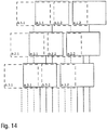
- Figure 14 finally shows a schematic representation to explain the spatial equalization of actuators, both in the vertical direction (ie at right angles to the nozzle plane) and in the horizontal direction (ie parallel to the nozzle plane).
- two rows of actuators are arranged one above the other, parallel to one another and parallel to the row of nozzles.
- the row of actuators on the right comprises two actuators a.1.1 and a.1.2, while the other row of actuators has two actuators b.1.1 and b.1.2 as an example.
- middle actuator level which also has two rows of actuators, each with two actuators a.2.1, a.2.2 or b.2.1 or b.2.2.
- the lower actuator level also contains two rows of actuators, each with two actuators a.3.1, a.3.2 and b.3.1, b.3.2, respectively.
Description
Die Erfindung betrifft einen Applikator (z.B. Druckkopf) zur Applikation eines Beschichtungsmittels (z.B. Lack) auf ein Bauteil (z.B. Kraftfahrzeugkarosseriebauteil oder Anbauteil für ein Kraftfahrzeugkarosseriebauteil).The invention relates to an applicator (e.g. print head) for applying a coating agent (e.g. paint) to a component (e.g. motor vehicle body component or add-on part for a motor vehicle body component).
Aus dem Stand der Technik (z.B.
Problematisch bei den bekannten Drop-on-Demand-Druckköpfen ist der Düsenabstand zwischen den benachbarten Düsen, wie nachfolgend unter Bezugnahme auf die
Darüber hinaus ist in
Aus
Zur Lösung dieses Problems des zu großen Düsenabstands d ist es aus dem Stand der Technik bekannt, den Druckkopf während des Betriebs um eine Drehachse 20 zu drehen, die rechtwinklig zur Oberfläche des Bauteils 6 und rechtwinklig zu der senkrecht zur Zeichenebene verlaufenden Lackierbahn verläuft. Dies hat zur Folge, dass der effektive Düsenabstand d in der Zeichenebene, d.h. rechtwinklig zur Lackierbahn, verringert wird. Diese Verdrehung des Drop-on-Demand-Druckkopfs ermöglicht es, dass die Beschichtungsmitteltröpfchen 17-19 auf der Oberfläche des Bauteils 6 so nah zusammen liegen, dass sie nach dem Auftragen zu einem durchgehenden Beschichtungsmittelfilm verlaufen, wie in
Zum technischen Hintergrund der Erfindung ist auch hinzuweisen auf
Schließlich offenbart
Der Erfindung liegt deshalb die Aufgabe zugrunde, einen entsprechend verbesserten Applikator (z.B. Druckkopf) zu schaffen.The invention is therefore based on the object of creating a correspondingly improved applicator (e.g. print head).
Diese Aufgabe wird durch einen erfindungsgemäßen Applikator gemäß dem Hauptanspruch gelöst.This object is achieved by an applicator according to the invention according to the main claim.
Der erfindungsgemäße Applikator (z.B. Druckkopf) eignet sich allgemein zur Applikation eines Beschichtungsmittels. Die Erfindung ist also hinsichtlich des Typs des zu applizierenden Beschichtungsmittels nicht auf ein bestimmtes Beschichtungsmittel beschränkt. Vorzugsweise ist der Druckkopf jedoch zur Applikation eines Lacks ausgelegt. Es kann sich jedoch bei dem Beschichtungsmittel alternativ auch um einen Klebstoff handeln oder um ein Dichtungsmaterial oder ein Dämmmaterial. Der erfindungsgemäße Applikator kann also auch als Klebstoff-Applikator oder als Sealing-Applikator ausgelegt sein.The applicator according to the invention (e.g. print head) is generally suitable for applying a coating agent. With regard to the type of coating agent to be applied, the invention is therefore not restricted to a specific coating agent. However, the print head is preferably designed for the application of a lacquer. However, the coating agent can alternatively also be an adhesive or a sealing material or an insulating material. The applicator according to the invention can therefore also be designed as an adhesive applicator or as a sealing applicator.
Weiterhin ist zu erwähnen, dass der erfindungsgemäße Druckkopf allgemein geeignet ist, um das Beschichtungsmittel (z.B. Lack) auf ein bestimmtes Bauteil zu applizieren. Hinsichtlich des Typs des zu beschichtenden Bauteils ist die Erfindung ebenfalls nicht beschränkt. Vorzugsweise ist der erfindungsgemäße Applikator jedoch dazu ausgelegt, ein Beschichtungsmittel (z.B. Lack) auf ein Kraftfahrzeugkarosseriebauteil oder ein Anbauteil eines Kraftfahrzeugkarosseriebauteils zu applizieren.It should also be mentioned that the print head according to the invention is generally suitable for applying the coating agent (for example paint) to a specific component. The invention is also not restricted with regard to the type of component to be coated. However, the applicator according to the invention is preferably designed to apply a coating agent (for example paint) to a motor vehicle body component or an add-on part of a motor vehicle body component.
Der erfindungsgemäße Applikator (z.B. Druckkopf) weist zunächst in Übereinstimmung mit dem Stand der Technik eine Düsenreihe mit mehreren Düsen auf, um das Beschichtungsmittel jeweils in Form eines Beschichtungsmittelstrahls zu applizieren, wobei die Düsen entlang der Düsenreihe vorzugsweise in einer gemeinsamen Düsenebene angeordnet sind.The applicator according to the invention (e.g. print head) initially has, in accordance with the prior art, a row of nozzles with several nozzles in order to apply the coating agent in each case in the form of a jet of coating agent, the nozzles being arranged along the row of nozzles, preferably in a common nozzle plane.
Hierbei ist zu erwähnen, dass der erfindungsgemäße Druckkopf aus den Düsen keinen Sprühkegel des Beschichtungsmittels abgibt, sondern jeweils räumlich begrenzte Beschichtungsmittelstrahlen (im Wesentlichen zusammenhängender Strahl oder Tropfenstrahl) mit einer nur geringen Strahlaufweitung. Der erfindungsgemäße Applikator unterscheidet sich also von Zerstäubern (z.B. Rotationszerstäuber, Luftzerstäuber, etc.), die keinen räumlich begrenzten Beschichtungsmittelstrahl abgeben, sondern einen Sprühkegel des Beschichtungsmittels.It should be mentioned here that the print head according to the invention does not emit a spray cone of the coating agent from the nozzles, but rather spatially limited jets of the coating agent (essentially continuous jet or jet of drops) with only a slight jet expansion. The applicator according to the invention thus differs from atomizers (e.g. rotary atomizers, air atomizers, etc.) which do not emit a spatially limited jet of coating agent, but rather a spray cone of the coating agent.
Weiterhin ist zu erwähnen, dass der erfindungsgemäße Applikator (z.B. Druckkopf) eine einzige Düsenreihe aufweisen kann, in der die Düsen vorzugsweise äquidistant angeordnet sind. Es besteht jedoch im Rahmen der Erfindung auch die Möglichkeit, dass der Druckkopf mehrere Düsenreihen aufweist, die vorzugsweise parallel zueinander angeordnet sind.It should also be mentioned that the applicator according to the invention (e.g. print head) can have a single row of nozzles, in which the nozzles are preferably arranged equidistantly. However, within the scope of the invention there is also the possibility that the print head has several rows of nozzles, which are preferably arranged parallel to one another.
Darüber hinaus weist der erfindungsgemäße Druckkopf in Übereinstimmung mit dem Stand der Technik mehrere Aktoren auf, um die Düsen wahlweise freizugeben oder zu verschließen, wie bereits eingangs zum Stand der Technik beschrieben wurde.In addition, in accordance with the prior art, the print head according to the invention has a plurality of actuators in order to selectively release or close the nozzles, as was already described at the beginning of the prior art.
Bei den Aktoren kann es sich beispielsweise - wie bereits eingangs beschrieben wurde - um elektromagnetische Aktoren handeln. Es besteht jedoch alternativ auch die Möglichkeit, dass es sich bei den Aktoren um piezoelektrische Aktoren oder um pneumatische Aktoren handelt, um nur einige Beispiele zu nennen. Die Erfindung ist also hinsichtlich des technisch-physikalischen Wirkungsprinzips der Aktoren nicht auf einen bestimmten Aktortyp beschränkt.The actuators can be, for example, as already described at the beginning, electromagnetic actuators. Alternatively, however, there is also the possibility that the actuators are piezoelectric actuators or pneumatic actuators, to name just a few examples. The invention is therefore not limited to a specific actuator type with regard to the technical-physical principle of action of the actuators.
Die Erfindung zeichnet sich nun dadurch ab, dass der Düsenabstand zwischen den benachbarten Düsen der Düsenreihe kleiner ist als die Außenabmessung (z.B. Außendurchmesser) der einzelnen Aktoren entlang der Düsenreihe. Die Erfindung überwindet also die eingangs beschriebene Untergrenze für den Düsenabstand, die bisher durch die Außenabmessung der einzelnen Aktoren gegeben war. So konnte der Düsenabstand zwischen den benachbarten Düsen der Düsenreihe bisher nicht kleiner bemessen sein als die Außenabmessung der einzelnen Aktoren, da der zur Verfügung stehende Bauraum für die Aktoren ansonsten nicht ausreichen würde. Hierbei ist zu erwähnen, dass der Düsenabstand jeweils zwischen den Mittelpunkten der Düsen gemessen wird.The invention is now characterized in that the nozzle spacing between the adjacent nozzles of the nozzle row is smaller than the outer dimension (for example outer diameter) of the individual actuators along the nozzle row. The invention thus overcomes the lower limit described at the beginning for the nozzle spacing, which was previously given by the external dimensions of the individual actuators. So the nozzle spacing between the adjacent nozzles of the nozzle row could not be made smaller than the outer dimensions of the individual actuators, since the available standing installation space for the actuators would otherwise not be sufficient. It should be mentioned here that the nozzle spacing is measured between the center points of the nozzles.
Diese Verringerung des Düsenabstands bei unveränderten Außenabmessungen der einzelnen Aktoren lässt sich im Rahmen der Erfindung durch eine fluidische Entzerrung des Applikators erreichen, indem die Steuerventile und/oder die Aktoren nicht mehr exakt in der Düsenreihe angeordnet werden, sondern versetzt dazu. So kann der erfindungsgemäße Applikator mehrere Steuerventile aufweisen, um die Beschichtungsmittelabgabe durch die Düsen zu steuern, wobei die Steuerventile von den Aktoren angesteuert werden. Die fluidische Entzerrung sieht dann vorzugsweise vor, dass die Steuerventile jeweils von der zugehörigen Düse räumlich getrennt und über jeweils einen Strömungskanal mit der zugehörigen Düse verbunden sind, um eine räumliche Entzerrung der Düsen einerseits und der Ventile andererseits zu ermöglichen. Die einzelnen Steuerventile sind hierbei mit ihrer Absperrstelle seitlich gegenüber der Düsenreihe versetzt angeordnet, um den Düsenabstand verringern zu können. Diese versetzte Anordnung der Steuerventile ermöglicht auch eine seitlich versetzte Anordnung der Aktoren, so dass der Düsenabstand nicht mehr durch die Außenabmessungen der einzelnen Aktoren nach unten begrenzt wird.This reduction in the nozzle spacing with unchanged outer dimensions of the individual actuators can be achieved within the scope of the invention by a fluidic equalization of the applicator in that the control valves and / or the actuators are no longer arranged exactly in the row of nozzles, but offset from them. Thus, the applicator according to the invention can have a plurality of control valves in order to control the release of the coating agent through the nozzles, the control valves being activated by the actuators. The fluidic equalization then preferably provides that the control valves are spatially separated from the associated nozzle and each connected to the associated nozzle via a flow channel in order to enable spatial equalization of the nozzles on the one hand and the valves on the other. The shut-off points of the individual control valves are offset laterally with respect to the row of nozzles in order to be able to reduce the nozzle spacing. This offset arrangement of the control valves also enables a laterally offset arrangement of the actuators, so that the nozzle spacing is no longer limited by the outer dimensions of the individual actuators.
In einer Ausgestaltung der Erfindung sind die Steuerventile beiderseits der Düsenreihe in zwei bezüglich der Düsenreihe gegenüber liegenden Ventilreihen hintereinander angeordnet. Die Düsen entlang der Düsenreihe können dann abwechselnd über die Strömungskanäle mit Steuerventilen der gegenüber überliegenden Ventilreihen verbunden sein. Beispielsweise kann die erste Düse der Düsenreihe mit einem Steuerventil der linken Ventilreihe verbunden sein, während die zweite Düse der Düsenreihe mit einem Steuerventil aus der rechten Ventilreihe verbunden ist. Die dritte Düse der Düsenreihe wird dann wieder mit einem Ventil aus der linken Ventilreihe verbunden und so weiter. Dadurch kann der Düsenabstand der benachbarten Düsen entlang der Düsenreihe auf die Hälfte der Außenabmessung der einzelnen Aktoren verringert werden.In one embodiment of the invention, the control valves are arranged one behind the other on both sides of the row of nozzles in two rows of valves lying opposite one another with respect to the row of nozzles. The nozzles along the row of nozzles can then alternately be connected via the flow channels to control valves of the opposite rows of valves. For example, the first nozzle of the row of nozzles can be connected to a control valve of the left row of valves, while the second nozzle of the row of nozzles is connected to a control valve of the right row of valves. The third nozzle of the nozzle row is then connected again to a valve from the left-hand row of valves and so on. As a result, the nozzle spacing of the adjacent nozzles along the row of nozzles can be reduced to half the external dimensions of the individual actuators.
In einer anderen Ausgestaltung der Erfindung gehen die Strömungskanäle von der Düsenreihe ausgehend in einer Entzerrungsebene rechtwinklig zu der Düsenreihe in mehr als zwei verschiedene Richtungen ab und zwar in verschiedenen Winkeln, wobei die verschiedenen Richtungen der Strömungskanäle in der Entzerrungsebene jeweils einen Winkel von 0°-90°, 20°-70°, 30°-60°, 40°-50° oder insbesondere 0° oder 45° einschließen können. Die Düsen entlang der Düsenreihe sind dann abwechselnd mit einem der verschiedenen Strömungskanäle verbunden. Die Aktoren sind hierbei also in der Entzerrungsebene in verschiedenen Winkellagen angeordnet und dadurch räumlich ebenfalls entzerrt, was eine größere Packungsdichte und einen entsprechend geringeren Düsenabstand ermöglicht.In another embodiment of the invention, the flow channels start from the row of nozzles in a rectification plane at right angles to the row of nozzles in more than two different directions, namely at different angles, the different directions of the flow channels in the rectification plane each at an angle of 0 ° -90 °, 20 ° -70 °, 30 ° -60 °, 40 ° -50 ° or in particular 0 ° or 45 °. The nozzles along the row of nozzles are then alternately connected to one of the various flow channels. The actuators are In this case, therefore, arranged in the rectification plane in different angular positions and thereby also rectified spatially, which enables a greater packing density and a correspondingly smaller nozzle spacing.
Gemäß der Erfindung sind die Aktoren in mehreren Aktorebenen angeordnet, wobei die Aktorebenen parallel zu der Düsenebene in verschiedenen Abständen zu der Düsenebene verlaufen. Die Aktoren in den einzelnen Aktorebenen sind hierbei jeweils in mehreren Aktorreihen parallel zu der Düsenreihe angeordnet, insbesondere beiderseits der Düsenreihe. Die Aktoren sind hierbei also vertikal entzerrt angeordnet, d.h. rechtwinklig zu der Düsenebene in verschiedenen Abständen. Darüber hinaus sind die Aktoren hierbei auch horizontal entzerrt angeordnet, d.h. parallel zur Düsenebene verteilt. Diese räumliche Entzerrung der Aktoren in verschiedenen Richtungen (horizontal und vertikal) ermöglicht ebenfalls eine Verringerung des Düsenabstands.According to the invention, the actuators are arranged in several actuator planes, the actuator planes running parallel to the nozzle plane at different distances from the nozzle plane. The actuators in the individual actuator levels are each arranged in several actuator rows parallel to the row of nozzles, in particular on both sides of the row of nozzles. The actuators are arranged in a vertically equalized manner, i.e. at right angles to the nozzle plane at different distances. In addition, the actuators are also arranged horizontally equalized, i.e. distributed parallel to the nozzle plane. This spatial equalization of the actuators in different directions (horizontal and vertical) also enables the nozzle spacing to be reduced.
In einer Ausgestaltung der Erfindung sind in den einzelnen Aktorebenen jeweils zwei Aktorreihen beiderseits der Düsenreihe angeordnet, wobei die Aktorreihen jeweils mehrere Aktoren enthalten.In one embodiment of the invention, two rows of actuators are arranged in each of the individual actuator levels on both sides of the row of nozzles, the rows of actuators each containing a plurality of actuators.
Hierbei haben die vertikal (d.h. rechtwinklig zu der Düsenebene und/oder zur Ventilsitzebene) übereinander angeordneten Aktorebenen zueinander vorzugsweise einen horizontalen Versatz, der im Wesentlichen gleich groß wie der Düsenabstand oder ein ganzzahliges Vielfaches des Düsenabstands zwischen den benachbarten Düsen in der Düsenreihe ist. Der Versatz kann jedoch auch einem ganzzahligen Vielfachen des Düsenabstands entsprechen. Darüber hinaus sind die Aktoren in den einzelnen Aktorreihen vorzugsweise im Wesentlichen äquidistant angeordnet.Here, the actuator planes arranged vertically (i.e. at right angles to the nozzle plane and / or to the valve seat plane) one above the other preferably have a horizontal offset that is essentially the same as the nozzle spacing or an integral multiple of the nozzle spacing between the adjacent nozzles in the nozzle row. However, the offset can also correspond to an integral multiple of the nozzle spacing. In addition, the actuators in the individual actuator rows are preferably arranged essentially equidistantly.
Weiterhin ist zu erwähnen, dass die Steuerventile in unterschiedlichen Abständen zu den zugehörigen Düsen angeordnet sein können. Dies hat zur Folge, dass die zugehörigen Strömungskanäle zwischen den Steuerventilen und den zugehörigen Düsen unterschiedliche Längen haben. Die unterschiedliche Länge der Strömungskanäle kann wiederum zu einem unterschiedlichen Strömungsverhalten führen, so dass die Beschichtungsmittelabgabe durch die einzelnen Düsen unterschiedlich ist. Es ist jedoch wünschenswert, dass die Beschichtungsmittelabgabe durch die einzelnen Düsen unabhängig von der Länge der Strömungskanäle einheitlich ist. Es ist deshalb im Rahmen der Erfindung möglich, die unterschiedliche Länge der Strömungskanäle durch Druckausgleichsmittel zu kompensieren, so dass die verschiedenen Düsen unabhängig von der Länge der zugehörigen Strömungskanäle ein einheitliches Abgabeverhalten haben.It should also be mentioned that the control valves can be arranged at different distances from the associated nozzles. As a result, the associated flow channels between the control valves and the associated nozzles have different lengths. The different lengths of the flow channels can in turn lead to different flow behavior, so that the coating agent release by the individual nozzles is different. However, it is desirable that the coating agent delivery through the individual nozzles is uniform regardless of the length of the flow channels. It is therefore possible within the scope of the invention to compensate for the different lengths of the flow channels by means of pressure compensation means to compensate so that the different nozzles have a uniform delivery behavior regardless of the length of the associated flow channels.
Beispielsweise können die Druckausgleichsmittel aus einem mäanderförmigen Verlauf, einem zickzackförmigen Kanalverlauf, einem spiralförmigen Kanalverlauf oder einer Kanalengstelle des Strömungskanals bestehen, wobei diese Druckausgleichsmittel vorzugsweise in den kürzeren Strömungskanälen angeordnet sind, da diese aufgrund ihrer geringeren Länge ansonsten einen geringeren Strömungswiderstand hätten.For example, the pressure equalization means can consist of a meander-shaped course, a zigzag-shaped channel course, a spiral-shaped channel course or a channel constriction of the flow channel, these pressure equalizing means preferably being arranged in the shorter flow channels, since they would otherwise have a lower flow resistance due to their shorter length.
Weiterhin ist zu erwähnen, dass die einzelnen Steuerventile jeweils einen Ventilsitz aufweisen können, der wahlweise verschlossen oder freigegeben werden kann. Die einzelnen Ventilsitze können im geöffneten Zustand einen lichten Durchmesser von 50µm-1500µm aufweisen.It should also be mentioned that the individual control valves can each have a valve seat that can optionally be closed or released. When open, the individual valve seats can have a clear diameter of 50 µm-1500 µm.
Darüber hinaus weisen die einzelnen Steuerventile ein auslenkbares Ventilelement auf, wobei es sich beispielsweise um eine flexible Ventilmembran handeln kann. Das auslenkbare Ventilelement (z.B. Ventilmembran) kann den Ventilsitz dann in Abhängigkeit von seiner Auslenkung wahlweise freigeben oder verschließen.In addition, the individual control valves have a deflectable valve element, which can be a flexible valve membrane, for example. The deflectable valve element (e.g. valve membrane) can then optionally release or close the valve seat depending on its deflection.
Zum Auslenken des Ventilelements (z.B. Ventilmembran) bestehen im Rahmen der Erfindung verschiedene Möglichkeiten, die nachfolgend kurz beschrieben werden.To deflect the valve element (e.g. valve membrane) there are various possibilities within the scope of the invention, which are briefly described below.
In einer Ausgestaltung der Erfindung ist ein verschiebbarer Stößel vorgesehen, der von dem zugehörigen Aktor verschoben wird und in einer Schließstellung das Ventilelement (z.B. Ventilmembran) gegen den Ventilsitz drückt und den Ventilsitz dadurch abdichtet.In one embodiment of the invention, a displaceable plunger is provided which is displaced by the associated actuator and, in a closed position, presses the valve element (e.g. valve membrane) against the valve seat and thereby seals the valve seat.
In einer anderen Ausgestaltung der Erfindung ist dagegen eine Druckkammer vorgesehen, die mit einem variablen Druck beaufschlagt werden kann, wobei der Druck in der Druckkammer auf das auslenkbare Ventilelement (z.B. Ventilmembran) wirkt. Durch eine ausreichende Druckbeaufschlagung der Druckkammer kann das Ventilelement (z.B. Ventilmembran) also gegen den Ventilsitz gedrückt werden und diesen dadurch abdichten. Beispielsweise kann die Druckkammer mit Druckluft beaufschlagt werden.In another embodiment of the invention, however, a pressure chamber is provided to which a variable pressure can be applied, the pressure in the pressure chamber acting on the deflectable valve element (eg valve membrane). By applying sufficient pressure to the pressure chamber, the valve element (for example valve membrane) can thus be pressed against the valve seat and thereby seal it off. For example, compressed air can be applied to the pressure chamber.
Hierbei ist zu erwähnen, dass sich das Ventilelement (z.B. Ventilmembran) über mehrere der Ventilsitze erstrecken kann, wobei das gemeinsame Ventilelement dann trotzdem individuell für die einzelnen Ventilsitze auslenkbar ist, damit die Beschichtungsmittelabgabe durch die einzelnen Düsen individuell gesteuert werden kann.It should be mentioned here that the valve element (e.g. valve membrane) can extend over several of the valve seats, whereby the common valve element can nevertheless be deflected individually for the individual valve seats so that the coating agent can be controlled individually by the individual nozzles.
Hierbei besteht auch die Möglichkeit, dass das Ventilelement (z.B. Ventilmembran) die gleiche Funktion erfüllt wie die eingangs zum Stand der Technik erwähnte Dichtungsmembran, die einen Aktorraum von einem beschichtungsmittelgefüllten Zuleitungsraum trennt und dadurch verhindert, dass die Aktoren in dem Aktorraum von dem Beschichtungsmittel kontaminiert werden. Das Ventilelement (z.B. Ventilmembran) hat hierbei also zwei Funktionen, nämlich zum einen das Öffnen bzw. Verschließen der Düsen und zum anderen die fluidische Trennung des Aktorraumes von dem Zuleitungsraum.There is also the possibility that the valve element (e.g. valve membrane) fulfills the same function as the sealing membrane mentioned at the beginning of the prior art, which separates an actuator chamber from a supply chamber filled with coating agent and thereby prevents the actuators in the actuator chamber from being contaminated by the coating agent . The valve element (e.g. valve membrane) has two functions, namely, on the one hand, opening or closing the nozzles and, on the other hand, the fluidic separation of the actuator space from the supply space.
Weiterhin ist zu erwähnen, dass die einzelnen Steuerventile jeweils eine Rückstellfeder aufweisen können, wobei die Rückstellfeder den Stößel in eine Schließstellung oder in eine Öffnungsstellung vorspannen kann. Vorzugsweise spannt die Rückstellfeder den Stößel jedoch in die Schließstellung vor, d.h. das zugehörige Steuerventil ist ohne eine aktive Ansteuerung geschlossen.It should also be mentioned that the individual control valves can each have a return spring, wherein the return spring can preload the plunger into a closed position or into an open position. However, the return spring preferably biases the plunger into the closed position, i.e. the associated control valve is closed without active activation.
Darüber hinaus kann anstelle einer Ventilmembran eine verschiebbare Ventilnadel vorgesehen sein, wobei die Ventilnadel den Ventilsitz in Abhängigkeit von ihrer Position wahlweise freigibt oder verschließt. Die Ventilnadel kann durch ein Dichtelement (z.B. Dichtungsmembran) hindurchgeführt sein, wobei das Dichtelement den Aktorraum von dem beschichtungsmittelgefüllten Zuleitungsraum trennt und dadurch verhindert, dass die Aktoren in dem Aktorraum von dem Beschichtungsmittel kontaminiert werden. Diese Ventilnadel kann an ihrer Spitze jeweils ein separates Dichtungselement aufweisen.In addition, instead of a valve membrane, a displaceable valve needle can be provided, the valve needle optionally releasing or closing the valve seat depending on its position. The valve needle can be passed through a sealing element (e.g. sealing membrane), the sealing element separating the actuator space from the feed space filled with the coating agent and thereby preventing the actuators in the actuator space from being contaminated by the coating agent. This valve needle can each have a separate sealing element at its tip.
Weiterhin ist zu erwähnen, dass die Ventilnadel bzw. der Stößel jeweils von einem Aktor verschoben werden können, wobei es sich beispielsweise um einen elektromagnetischen Aktor, einen piezoelektrischen Aktor oder einen pneumatischen Aktor handeln kann. Die Erfindung ist also hinsichtlich des technisch-physikalischen Wirkungsprinzips des Aktors nicht auf ein bestimmtes Wirkungsprinzip beschränkt.It should also be mentioned that the valve needle or the tappet can each be moved by an actuator, which can be, for example, an electromagnetic actuator, a piezoelectric actuator or a pneumatic actuator. The invention is therefore not limited to a specific operating principle with regard to the technical-physical operating principle of the actuator.
Darüber hinaus ist zu erwähnen, dass die einzelnen Aktoren wahlweise einfach oder doppelt wirkend sein können. Bei einem einfach wirkenden Aktor wird die Ventilnadel bzw. der Stößel von dem zugehörigen Aktor nur in eine einzige Richtung aktiv bewegt, wohingegen die Rückstellbewegung durch eine Rückstellfeder bewirkt wird. Bei einem doppelt wirkenden Aktor werden dagegen beide Bewegungen in den entgegengesetzten Richtungen von dem zugehörigen Aktor aktiv bewirkt, so dass auf eine Rückstellfeder auch verzichtet werden könnte.It should also be mentioned that the individual actuators can be either single or double-acting. In the case of a single-acting actuator, the valve needle or the tappet is only actively moved in a single direction by the associated actuator, whereas the return movement is brought about by a return spring. In the case of a double-acting actuator, on the other hand, both movements in the opposite directions are actively brought about by the associated actuator, so that a return spring could also be dispensed with.
Ferner besteht auch die Möglichkeit, dass die einzelnen Steuerventile außerhalb des Applikators angeordnet sind, wobei die Steuerventile dann durch eine Fluidleitung (z.B. Schlauch) mit dem Applikator verbunden sind.Furthermore, there is also the possibility that the individual control valves are arranged outside the applicator, the control valves then being connected to the applicator by a fluid line (e.g. hose).
Der erfindungsgemäße Applikator kann auch einen gemeinsamen Versorgungskanal aufweisen, um die einzelnen Strömungskanäle für die einzelnen Ventile mit dem Beschichtungsmittel zu speisen. Beispielsweise kann dieser Versorgungskanal eine Kanalhöhe von 100µm-2000µm, eine Kanalbreite von 1mm-5mm und/oder eine Kanallänge von 1mm-100mm aufweisen.The applicator according to the invention can also have a common supply channel in order to feed the individual flow channels for the individual valves with the coating agent. For example, this supply channel can have a channel height of 100 μm-2000 μm, a channel width of 1 mm-5 mm and / or a channel length of 1 mm-100 mm.
Die erfindungsgemäße Verringerung des Düsenabstandes ermöglicht es, dass der Abstand zwischen den benachbarten Ventilsitzen mindestens doppelt so groß ist wie der Düsenabstand zwischen den benachbarten Düsen.The reduction in the nozzle spacing according to the invention makes it possible for the spacing between the adjacent valve seats to be at least twice as large as the nozzle spacing between the adjacent nozzles.
Der Strömungskanal und/oder der Versorgungskanal in dem Applikator können durch verschiedene Herstellungsverfahren hergestellt werden. Beispielhaft sind die folgenden Herstellungsverfahren zu nennen:
- Lithographieverfahren, insbesondere Weichlithographieverfahren,
- 3D-Druck,
- Opferschichtverfahren,
- Escargot-Verfahren,
- LIGA-Verfahren,
- thermisches Bonden,
- Diffusionsschweißen,
- Laserabtragen,
- Laserschneiden,
- Verkleben, Heißprägen,
- Ätzverfahren,
- Spritzgießen,
- selektives Lasersintern,
- selektives Laserschmelzen,
- mechanisches Bearbeiten,
- eine Kombination der vorstehend genannten Verfahren.
- Lithography process, especially soft lithography process,
- 3D printing,
- Sacrificial layer process,
- Escargot procedure,
- LIGA procedure,
- thermal bonding,
- Diffusion welding,
- Laser ablation,
- Laser cutting,
- Gluing, hot stamping,
- Etching process,
- Injection molding,
- selective laser sintering,
- selective laser melting,
- mechanical processing,
- a combination of the above methods.
Der Strömungskanal und/oder der Versorgungskanal können hierbei in einem Substrat (d.h. einem Gehäusekörper) verlaufen, das aus einem Material besteht, das gegenüber dem Beschichtungsmittel inert ist. Beispielsweise kann das Substrat aus Edelstahl, Kunststoff, Silizium oder Glas bestehen. Als Kunststoffe kommen beispielsweise folgende Kunststoffe in Frage:
- Polyetheretherketon (PEEK),
- Polyetherketon (PEKK),
- Polyoxymethylen (POM),
- Polymethylmethacrylat (PMMA),
- Polyamid (PA),
- Polyethylen (PE),
- Polypropylen (PP),
- Polystyrol (PS),
- Polycarbonat (PC),
- Cycloolefin-Copolymere, insbesondere Topas®, Zeonor® oder Zeonex®.
- Polyetheretherketone (PEEK),
- Polyether ketone (PEKK),
- Polyoxymethylene (POM),
- Polymethyl methacrylate (PMMA),
- Polyamide (PA),
- Polyethylene (PE),
- Polypropylene (PP),
- Polystyrene (PS),
- Polycarbonate (PC),
- Cycloolefin copolymers, in particular Topas®, Zeonor® or Zeonex®.
Zu den Strömungskanälen ist ferner zu erwähnen, dass diese mindestens auf einem Teil ihrer Länge einen Winkel von 0-90°, 20°-85°, 45°-80° mit dem Beschichtungsmittelstrahl einschließen können.With regard to the flow channels, it should also be mentioned that they can enclose an angle of 0-90 °, 20 ° -85 °, 45 ° -80 ° with the coating agent jet over at least part of their length.
Weiterhin können die Strömungskanäle mindestens auf einem Teil ihrer Länge in einem Winkel von 0-90° oder 45°-90° oder quer, insbesondere rechtwinklig, zu der Düsenreihe verlaufen.Furthermore, the flow channels can run at least over part of their length at an angle of 0-90 ° or 45 ° -90 ° or transversely, in particular at right angles, to the row of nozzles.
Die einzelnen Strömungskanäle können jeweils einen Kanalquerschnitt mit einer Kanalhöhe von 50µm-1000µm oder 100µm-500µm aufweisen.The individual flow channels can each have a channel cross-section with a channel height of 50 µm-1000 µm or 100 µm-500 µm.
Die Kanalbreite der einzelnen Strömungskanäle liegt dagegen vorzugsweise im Bereich von 50µm-1000µm oder 100µm-500µm.In contrast, the channel width of the individual flow channels is preferably in the range of 50 μm-1000 μm or 100 μm-500 μm.
Die Kanallänge der einzelnen Strömungskanäle liegt dagegen vorzugsweise im Bereich von 0,1mm-50mm oder 0,5mm-25mm. Eine kurze Kanallänge ist hierbei wünschenswert, damit die Strömungskanäle zwischen der Absperrstelle der Steuerventile einerseits und den Düsen andererseits ein möglichst kleines Volumen aufweisen, damit ein Nachtropfen verhindert wird und ein gutes dynamisches Ansprechverhalten erreicht wird. Das Volumen der Strömungskanäle zwischen der Absperrstelle der Steuerventile und den Düsen ist deshalb vorzugsweise kleiner als 1mL, 0,5mL, 0,1mL, 0,01mL oder 0,001mL.The channel length of the individual flow channels, on the other hand, is preferably in the range of 0.1 mm-50 mm or 0.5 mm-25 mm. A short channel length is desirable here so that the flow channels between the shut-off point of the control valves on the one hand and the nozzles on the other hand have the smallest possible volume so that dripping is prevented and a good dynamic response is achieved. The volume of the flow channels between the shut-off point of the control valves and the nozzles is therefore preferably less than 1mL, 0.5mL, 0.1mL, 0.01mL or 0.001mL.
Weiter ist zu erwähnen, dass die Strömungskanäle auch einen runden Kanalquerschnitt aufweisen können, insbesondere mit einem Kanaldurchmesser von 50µm-1000µm.It should also be mentioned that the flow channels can also have a round channel cross-section, in particular with a channel diameter of 50 μm-1000 μm.
Die Erfindung ermöglicht einen sehr kleinen Düsenabstand der benachbarten Düsen entlang der Düsenreihe, wobei der Düsenabstand kleiner sein kann als 3mm, 2mm, 1mm oder sogar kleiner als 0,5mm.The invention enables a very small nozzle spacing of the adjacent nozzles along the nozzle row, wherein the nozzle spacing can be less than 3 mm, 2 mm, 1 mm or even less than 0.5 mm.
Die Steuerventile sind dagegen mit ihren Absperrstellen vorzugsweise in einem Abstand von mindestens 1mm, 2mm, 3mm, 4mm, 5mm oder 6mm zu der Düsenreihe angeordnet, um eine räumliche Entzerrung der Steuerventile einerseits und der Düsen andererseits zu ermöglichen.The control valves, on the other hand, are preferably arranged with their shut-off points at a distance of at least 1mm, 2mm, 3mm, 4mm, 5mm or 6mm from the row of nozzles in order to enable spatial equalization of the control valves on the one hand and the nozzles on the other.
Ferner ist zu erwähnen, dass die Düsen entlang der Düsenreihe vorzugsweise äquidistant angeordnet sind.It should also be mentioned that the nozzles are preferably arranged equidistantly along the row of nozzles.
Darüber hinaus ist zu erwähnen, dass die Erfindung nicht nur Schutz beansprucht für den vorstehend beschriebenen erfindungsgemäßen Applikator. Vielmehr beansprucht die Erfindung auch Schutz für einen Beschichtungsroboter (z.B. Lackierroboter) mit einem solchen Applikator.In addition, it should be mentioned that the invention not only claims protection for the applicator according to the invention described above. Rather, the invention also claims protection for a coating robot (e.g. painting robot) with such an applicator.
Andere vorteilhafte Weiterbildungen der Erfindung sind in den Unteransprüchen gekennzeichnet oder werden nachstehend zusammen mit der Beschreibung der bevorzugten Ausführungsbeispiele der Erfindung anhand der Figuren näher erläutert. Es zeigen:
Figur 1- eine schematische Darstellung eines herkömmlichen Druckkopfs, wobei die Beschichtungsmitteltropfen nicht zu einem zusammenhängenden Beschichtungsmittelfilm zusammenlaufen,
Figur 2- eine
Abwandlung von Figur 1 mit einem gedrehten Druckkopf, so dass die Beschichtungsmitteltröpfchen zu einem zusammenhängenden Beschichtungsmittelfilm zusammenlaufen, Figur 3- eine schematische Darstellung eines herkömmlichen Druckkopfs,
Figur 4- eine schematische Schnittansicht durch einen herkömmlichen Druckkopf zur Verdeutlichung der Düsenabstände,
Figur 5- eine schematische Darstellung eines nicht erfindungsgemäßen Druckkopfs,
Figur 6- eine schematische Darstellung zur Verdeutlichung der räumlichen Entzerrung der Steuerventile in seitlicher Richtung,
Figur 7- eine schematische Darstellung zur Verdeutlichung von Druckausgleichsmitteln in den einzelnen Strömungskanälen,
Figur 8- eine schematische Darstellung zur Verdeutlichung der seitlichen Entzerrung der Steuerventile,
- Figur 9A
- eine schematische Darstellung eines Beispiels eines nicht erfindungsgemäßen Druckkopfs mit einem Steuerventil mit einer stößelbetätigten Ventilmembran im geöffneten Zustand,
- Figur 9B
- den Druckkopf gemäß
Figur 9A in einer geschlossenen Stellung, - Figur 10A
- eine Abwandlung von
Figur 9A mit einer Druckkammer zur Auslenkung der Ventilmembran, wobei die Ventilmembran im geöffneten Zustand gezeigt ist, - Figur 10B
- eine Abwandlung von
Figur 10A im geschlossenen Zustand der Ventilmembran, - Figur 11A
- eine Abwandlung von
Figur 9A mit einem separaten Ventilstößel, der durch eine Dichtungsmembran verschiebbar hindurchgeführt ist und im geöffneten Zustand gezeigt ist, - Figur 11B
- die Darstellung gemäß
Figur 11A im geschlossenen Zustand des Steuerventils, Figur 12- eine Abwandlung von
Figur 9A , wobei die Steuerventile außerhalb des Druckkopfs angeordnet sind, Figur 13- eine schematische Darstellung zur räumlichen Entzerrung der Steuerventile in verschiedenen Richtungen,
Figur 14- eine schematische Darstellung zur räumlichen Entzerrung der Aktoren in vertikaler und horizontaler Richtung.
- Figure 1
- a schematic representation of a conventional printhead, wherein the coating agent droplets do not converge to form a coherent coating agent film,
- Figure 2
- a variation of
Figure 1 with a rotated printhead so that the coating agent droplets converge to form a coherent coating agent film, - Figure 3
- a schematic representation of a conventional print head,
- Figure 4
- a schematic sectional view through a conventional print head to illustrate the nozzle spacing,
- Figure 5
- a schematic representation of a print head not according to the invention,
- Figure 6
- a schematic representation to illustrate the spatial equalization of the control valves in the lateral direction,
- Figure 7
- a schematic representation to illustrate pressure compensation means in the individual flow channels,
- Figure 8
- a schematic representation to illustrate the lateral equalization of the control valves,
- Figure 9A
- a schematic representation of an example of a print head not according to the invention with a control valve with a plunger-actuated valve membrane in the open state,
- Figure 9B
- the printhead according to
Figure 9A in a closed position, - Figure 10A
- a variation of
Figure 9A with a pressure chamber for deflecting the valve membrane, the valve membrane being shown in the open state, - Figure 10B
- a variation of
Figure 10A when the valve membrane is closed, - Figure 11A
- a variation of
Figure 9A with a separate valve tappet, which is slidably guided through a sealing membrane and is shown in the open state, - Figure 11B
- the representation according to
Figure 11A when the control valve is closed, - Figure 12
- a variation of
Figure 9A with the control valves located outside the printhead, - Figure 13
- a schematic representation of the spatial equalization of the control valves in different directions,
- Figure 14
- a schematic representation of the spatial equalization of the actuators in the vertical and horizontal direction.
Im Folgenden wird nun unter Bezugnahme auf die
Hierbei sind in einer linearen Düsenreihe 21 zahlreiche Düsen 22-28 äquidistant angeordnet. Beiderseits der Düsenreihe 21 befinden sich hierbei parallele Ventilsitzreihen 29, 30.Here, numerous nozzles 22-28 are arranged equidistantly in a linear row of
In der Ventilsitzreihe 29 sind zahlreiche Ventilsitze 31-34 in einem Abstand a äquidistant angeordnet. Die Ventilsitze 31-34 werden jeweils durch Aktoren geöffnet bzw. geschlossen, wobei die Aktoren 35-38 jeweils eine nicht dargestellte Ventilnadel verschließen, um die Ventilsitze 31-34 individuell verschließen bzw. öffnen zu können.In the
In der gegenüberliegenden Ventilsitzreihe 30 sind ebenfalls mehrere Ventilsitze 39-41 in dem Abstand a äquidistant angeordnet. Diese Ventilsitze 39-41 werden ebenfalls über Aktoren 42-44 geschlossen bzw. geöffnet, wobei die Aktoren 42-44 jeweils eine nicht dargestellte Ventilnadel verschieben, um die Ventilsitze 39-41 zu öffnen bzw. zu schließen.In the opposite row of
Die Ventilsitze 31-34 der in der Zeichnung oberen Ventilsitzreihe 29 sind hierbei jeweils durch Strömungskanäle 45-48 mit den zugehörigen Düsen 22, 24, 26, 28 verbunden.The valve seats 31-34 of the upper row of
Die Ventilsitze 39-41 der in der Zeichnung unteren Ventilsitzreihe 30 sind entsprechend über Strömungskanäle 49-51 mit den zugehörigen Düsen 23, 25, 27 verbunden.The valve seats 39-41 of the lower row of
Bei dieser Anordnung sind die Aktoren 35-38 gegenüber der Düsenreihe 21 in der Zeichnung nach oben versetzt, während die Aktoren 42-44 in der Zeichnung nach unten gegenüber der Düsenreihe 21 versetzt sind. Diese räumliche Entzerrung der Aktoren 35-38 bzw. 42-44 einerseits und der Düsenreihe 21 andererseits ermöglicht eine Verringerung des Düsenabstands d unter den Abstand a zwischen den benachbarten Aktoren 35-38 bzw. 42-44. Insbesondere kann der Düsenabstand d der benachbarten Düsen 22-28 auch kleiner sein als der Durchmesser b der einzelnen Aktoren 35-38 bzw. 42-44.In this arrangement, the actuators 35-38 are offset upward in the drawing with respect to the row of
Aus der Querschnittsansicht in
Weiterhin ist aus
Teilweise stimmte diese Darstellung mit den vorangehenden Zeichnungen überein, so dass zur Vermeidung von Wiederholungen auf die vorstehende Beschreibung verwiesen wird, wobei für entsprechende Einzelheiten dieselben Bezugszeichen verwendet werden.This representation partially coincides with the preceding drawings, so that in order to avoid repetition, reference is made to the preceding description, the same reference symbols being used for corresponding details.
Hierbei sind Strömungskanäle 55, 56 vorgesehen, die alle gleich lang sind. Dies bietet den Vorteil, dass der Strömungswiderstand der Strömungskanäle 55, 56 einheitlich ist, so dass das Applikationsverhalten der einzelnen Düsen ebenfalls einheitlich ist.
Eine Besonderheit dieses Ausführungsbeispiels besteht darin, dass der Druckkopf lange Strömungskanäle 57 und kurze Strömungskanäle 58 aufweist. Dies ist problematisch, weil der Strömungswiderstand der kurzen Strömungskanäle 58 in der Regel geringer ist als der Strömungswiderstand der langen Strömungskanäle 57, was zu einem entsprechend unterschiedlichen Applikationsverhalten führen würde. In den kurzen Strömungskanälen 58 sind deshalb hierbei Druckausgleichsmittel 59 angeordnet, die in diesem Ausführungsbeispiel aus einem mäanderförmigen Verlauf der kurzen Strömungskanäle 58 bestehen.A special feature of this exemplary embodiment is that the print head has
Im Folgenden wird nun das Ausführungsbeispiel gemäß den
Die Zeichnungen zeigen eine schematische Detaildarstellung des Druckkopfs im Bereich einer Düse 60, wobei durch die Düse 60 ein Beschichtungsmittelstrahl 61 auf ein Bauteil 62 abgegeben werden kann.The drawings show a schematic detailed illustration of the print head in the area of a
Die Düse 60 ist hierbei über einen Strömungskanal 63 mit einem zu der Düse 60 seitlich versetzten Ventilsitz 64 verbunden, wobei der Strömungskanal 63 in einem Substrat 65 verläuft. In die Oberfläche des Substrats 65 ist ein Versorgungskanal 66 eingebettet, der zu dem Ventilsitz 64 führt.The
Darüber hinaus ist an der Oberseite des Substrats 65 eine Ventilmembran 67 mittels einer Membranklemmung 68 fixiert, wobei die Ventilmembran 67 zwischen der Öffnungsstellung gemäß
Zum Auslenken der Ventilmembran 67 dient ein Ventilstößel 69, der in einer Stößelführung 70 verschiebbar geführt ist und von einem Aktor in Richtung des Doppelpfeils verschoben werden kann.A
Der Ventilstößel 69 wird von einer Rückstellfeder 71 nach unten in die Schließstellung gedrückt. In der Schließstellung gemäß
Der seitliche Versatz zwischen der Düse 60 und dem Ventilsitz 64 ermöglicht es hierbei, dass der Düsenabstand zwischen den benachbarten Düsen (d.h. rechtwinklig zur Zeichenebene) verringert wird.The lateral offset between the
Die
Die
Eine Besonderheit dieses Ausführungsbeispiels besteht darin, dass der Ventilsitz 64 hierbei nicht von der Ventilmembran 67 verschlossen wird. Vielmehr ist hierbei durch die Ventilmembran 67 eine Ventilnadel 73 hindurchgeführt, die in Richtung des Doppelpfeils verschiebbar ist und an ihrer Spitze ein separates Dichtelement 74 trägt. In der Schließstellung gemäß
Die Ventilmembran 67 hat hierbei nur die Funktion, den beschichtungsmittelgefüllten Versorgungskanal 66 von einem Aktorraum zu trennen, damit der Aktorraum nicht von dem Beschichtungsmittel in dem Versorgungskanal 66 kontaminiert wird.The
Eine Besonderheit dieses Ausführungsbeispiels besteht darin, dass hierbei die Steuerventile von dem Druckkopf getrennt sind und über einen Schlauch 75 mit dem Druckkopf verbunden werden.A special feature of this exemplary embodiment is that in this case the control valves are separated from the print head and are connected to the print head via a hose 75.
Hierbei sind die Düsen 78 entlang der Düsenreihe (d.h. rechtwinklig zur Zeichenebene) über Strömungskanäle 80-84 abwechselnd mit Ventilsitzen in verschiedenen Winkelausrichtungen verbunden. Die Zeichenebene bildet hierbei also eine Entzerrungsebene, wobei die Strömungskanäle 80-84 in verschiedene Richtungen weisen und dadurch eine räumliche Entzerrung ermöglichen, was wiederum eine Verringerung des Düsenabstands d erlaubt.Here, the
Hierbei sind in drei exemplarisch dargestellten Aktorebenen übereinander jeweils zwei Aktorreihen parallel zueinander und parallel zur Düsenreihe angeordnet.Here, in three actuator levels shown as an example, two rows of actuators are arranged one above the other, parallel to one another and parallel to the row of nozzles.
In der oberen Aktorebene umfasst die rechte Aktorreihe exemplarisch zwei Aktoren a.1.1 und a.1.2, während die andere Aktorreihe exemplarisch zwei Aktoren b.1.1 und b.1.2 aufweist.In the upper actuator level, the row of actuators on the right comprises two actuators a.1.1 and a.1.2, while the other row of actuators has two actuators b.1.1 and b.1.2 as an example.
Das Gleiche gilt für die mittlere Aktorebene, die ebenfalls zwei Aktorreihen mit jeweils zwei Aktoren a.2.1, a.2.2 bzw. b.2.1 bzw. b.2.2 aufweist.The same applies to the middle actuator level, which also has two rows of actuators, each with two actuators a.2.1, a.2.2 or b.2.1 or b.2.2.
Schließlich enthält auch die untere Aktorebene zwei Aktorreihen mit exemplarisch jeweils zwei Aktoren a.3.1, a.3.2 bzw. b.3.1, b.3.2.Finally, the lower actuator level also contains two rows of actuators, each with two actuators a.3.1, a.3.2 and b.3.1, b.3.2, respectively.
Hierbei ist zu erwähnen, dass die Anzahl der Aktoren in den einzelnen Aktorreihen in der Praxis wesentlich größer ist als vorstehend zur Veranschaulichung dargestellt und beschrieben wurde.It should be mentioned here that the number of actuators in the individual actuator rows is significantly greater in practice than was shown and described above for illustration.
- 11
- DüsenplatteNozzle plate
- 2-42-4
- DüsenNozzles
- 55
- DüsenreiheRow of nozzles
- 66th
- BauteilComponent
- 7-97-9
- AktorenActuators
- 10-1210-12
- VentilnadelnValve needles
- 1313th
- DichtungsmembranSealing membrane
- 1414th
- DüsenraumNozzle space
- 1515th
- AktorraumActuator room
- 1616
- MembranentkopplungMembrane decoupling
- 17-1917-19
- BeschichtungsmitteltröpfchenCoating agent droplets
- 2020th
- DrehachseAxis of rotation
- 2121
- DüsenreiheRow of nozzles
- 22-2822-28
- DüsenNozzles
- 29, 3029, 30
- VentilsitzreihenValve seat rows
- 31-3431-34
- VentilsitzeValve seats
- 35-3835-38
- AktorenActuators
- 39-4139-41
- VentilsitzeValve seats
- 42-4442-44
- AktorenActuators
- 45-4845-48
- StrömungskanäleFlow channels
- 49-5149-51
- StrömungskanäleFlow channels
- 5252
- SubstratSubstrate
- 5353
- VersorgungskanalSupply channel
- 5454
- BeschichtungsmittelstrahlCoating agent jet
- 55, 5655, 56
- StrömungskanäleFlow channels
- 5757
- Lange StrömungskanäleLong flow channels
- 5858
- Kurze StrömungskanäleShort flow channels
- 5959
- DruckausgleichsmittelPressure equalization means
- 6060
- Düsejet
- 6161
- BeschichtungsmittelstrahlCoating agent jet
- 6262
- BauteilComponent
- 6363
- StrömungskanalFlow channel
- 6464
- VentilsitzValve seat
- 6565
- SubstratSubstrate
- 6666
- VersorgungskanalSupply channel
- 6767
- VentilmembranValve membrane
- 6868
- MembranklemmungDiaphragm clamping
- 6969
- VentilstößelValve lifters
- 7070
- StößelführungSlide guide
- 7171
- RückstellfederReturn spring
- 7272
- DruckkammerPressure chamber
- 7373
- VentilnadelValve needle
- 7474
- Dichtelement der VentilnadelSealing element of the valve needle
- 7575
- Schlauchhose
- 7676
- DruckkopfPrinthead
- 7777
- BeschichtungsmittelstrahlCoating agent jet
- 7878
- Düsejet
- 7979
- BauteilComponent
- 80-8480-84
- StrömungskanäleFlow channels
- a.1.1a.1.1
- Aktor der rechten Aktorreihe der oberen AktorebeneActuator of the right actuator row of the upper actuator level
- a.1.2a.1.2
- Aktor der rechten Aktorreihe der oberen AktorebeneActuator of the right actuator row of the upper actuator level
- b.1.1b.1.1
- Aktor der linken Aktorreihe der oberen AktorebeneActuator of the left actuator row of the upper actuator level
- b.1.2b.1.2
- Aktor der linken Aktorreihe der oberen AktorebeneActuator of the left actuator row of the upper actuator level
- a.2.1a.2.1
- Aktor der rechten Aktorreihe der mittleren AktorebeneActuator of the right actuator row of the middle actuator level
- a.2.2a.2.2
- Aktor der rechten Aktorreihe der mittleren AktorebeneActuator of the right actuator row of the middle actuator level
- b.2.1b.2.1
- Aktor der linken Aktorreihe der mittleren AktorebeneActuator of the left actuator row of the middle actuator level
- b.2.2b.2.2
- Aktor der linken Aktorreihe der mittleren AktorebeneActuator of the left actuator row of the middle actuator level
- a.3.1a.3.1
- Aktor der rechten Aktorreihe der unteren AktorebeneActuator of the right actuator row of the lower actuator level
- a.3.2a.3.2
- Aktor der rechten Aktorreihe der unteren AktorebeneActuator of the right actuator row of the lower actuator level
- b.3.1b.3.1
- Aktor der linken Aktorreihe der unteren AktorebeneActuator of the left actuator row of the lower actuator level
- b.3.2b.3.2
- Aktor der linken Aktorreihe der unteren AktorebeneActuator of the left actuator row of the lower actuator level
- αα
- Winkel zwischen Strömungskanal und BeschichtungsmittelstrahlAngle between flow channel and coating agent jet
- ββ
- Winkel zwischen Strömungskanal und DüsenreiheAngle between flow channel and row of nozzles
- aa
- Abstand der benachbarten AktorenDistance between the neighboring actuators
- bb
- Durchmesser der AktorenActuator diameter
- dd
- DüsenabstandNozzle spacing
Claims (14)
- Applicator, in particular printhead, for applying a coating agent, in particular a paint, to a component, in particular to a motor vehicle body component or an add-on part for a motor vehicle body component, havinga) at least one nozzle row (21) having a plurality of nozzles (22-28; 60; 78) for dispensing the coating agent in the form of a coating agent jet (54; 61; 77), the nozzles (22-28; 60; 78) being arranged one behind the other along each nozzle row (21) at a specific nozzle spacing (d) in a nozzle plane, andb) a plurality of actuators (a.1.1-b.3.2) for controlling the release of the coating agent through the individual nozzles (22-28; 60; 78),b1) wherein the actuators (a.1.1-b.3.2) each having an outer dimension (b) along the respective nozzle row (21),b2) wherein the actuators (a.1.1-b.3.2) are arranged in a plurality of actuator planes, wherein the individual actuator planes extending parallel to the nozzle plane at different distances from the nozzle plane,c) wherein the nozzle spacing (d) between the adjacent nozzles (22-28; 60; 78) of the nozzle row (21) is smaller than the outer dimension (b) of the individual actuators (a.1.1-b.3.2) along the respective nozzle row (21),d) wherein the actuators (a.1.1-b.3.2) in the individual actuator planes are each arranged in a plurality of actuator rows parallel to the nozzle row (21), in particular on both sides of the respective nozzle row (21),
characterized ine) that the actuators arranged vertically one above the other have a horizontal offset with respect to one another which is substantially equal in magnitude to the nozzle spacing (d) between the adjacent nozzles in the nozzle row or corresponds to an integer multiple of the nozzle spacing. - Applicator according to claim 1, characterized ina) that the applicator has a plurality of control valves (31-34, 39-41) for controlling the release of the coating agent through the nozzles (2-4), the control valves (31-34, 39-41) being driven by the actuators (a.1.1-b.3.2),b) that the control valves (31-34, 39-41) are each spatially separated from the associated nozzle (22-28) and are each connected to the associated nozzle (22-28) via a flow channel (45-51) in order to enable spatial pulling-apart of the nozzles (22-28) on the one hand and of the control valves on the other hand, andc) that the control valves (31-34, 39-41) are arranged with their shut-off point offset laterally with respect to the nozzle row (21) in order to be able to reduce the nozzle spacing (d).
- Applicator according to claim 2, characterized ina) that the control valves (31-34, 39-41) are arranged on either side of the respective nozzle row (21) in two valve rows (29, 30) which are opposite one another with respect to the respective nozzle row (21), andb) that the nozzles (22-28) are connected along the nozzle row (21) alternately via the flow channels (45-51) to control valves (31-34, 39-41) of the opposite valve rows (29, 30).
- Applicator according to claim 2, characterized ina) that the flow channels (80-84) depart from the respective nozzle row in a pulling-apart plane at right angles to the respective nozzle row in more than two different directions, and/orb) that the different directions of the flow channels (80-84) in the pulling-apart plane each include an angle of 20°-70°, 30°-60°, 40°-50° or 45°, andc) that the nozzles (78) are connected to one of the different flow channels (80-84) alternately along the respective nozzle row.
- Applicator according to any of the preceding claims, characterized ina) that the individual actuator planes extend parallel to the nozzle plane, andb) that two actuator rows are arranged in each of the individual actuator planes on either side of the respective nozzle row, the actuator rows each containing a plurality of actuators (a.1.1-b.3.2), and/orc) that the actuators in the actuator rows are arranged substantially equidistantly.
- Applicator according to one of claims 2 to 5, if dependent on claim 2, characterized ina) that the distance between the control valves and the associated nozzles is partly different, so that the flow channels (57, 58) bridge partly different distances, andb) that the flow channels (57, 58) have pressure compensation means (59) for compensating the different distances, the pressure compensation means (59) at least partially compensating the different pressure losses along the flow channels (57, 58) of different lengths, andc) that the pressure compensation means (59) comprise the following, in particular in the flow channels with the shorter distances from the nozzle to the valve seat:c1) a meandering course,c2) a zigzag channel shape,c3) a spiral channel shape; and/orc4) a channel narrowing.
- Applicator according to one of claims 2 to 6, if dependent on claim 2, characterized in,a) that the individual control valves each have a valve seat (31-34, 39-41; 64), which can be selectively closed or released, andb) that the individual valve seats (31-34, 39-41; 64) each have a clear diameter of 50µm-1500µm, and/orc) that a deflectable valve element (67), in particular a valve membrane (67), is provided, this valve element (67) selectively releasing or closing the valve seat (64) as a function of its deflection, andd) that for the deflection of the valve element (67)d1) a displaceable plunger (6) is provided which, in a closed position, presses the valve element (67) against the valve seat (64) and thereby seals the latter, ord2) a pressure chamber (72) is provided, the pressure chamber (72) applying an adjustable pressure to the valve element (67) in order to selectively press the valve element (67) against the valve seat (64) and thereby seal it or release the valve seat (64).
- Applicator according to claim 7, characterized ina) that a displaceable valve needle (73) is provided, the valve needle (73) selectively releasing or closing the valve seat (64) as a function of its position, andb) that the valve needle (73) is passed through a sealing element (67), in particular through a sealing membrane (67), the sealing element (67) separating an actuator chamber from a feed line chamber filled with coating agent and thereby preventing the actuators in the actuator chamber from being contaminated by the coating agent, andc) that the valve needle (73) has a separate sealing element (74) at its tip,d) that the valve needle (73) is displaced by one of the actuators (a.1.1-b.3.2), in particular byd1) an electromagnetic actuator,d2) a piezoelectric actuator; ord3) a pneumatic actuator,e) that the actuators (a.1.1-b.3.2) aree1) each single-acting and actively move the valve needle (73) or the plunger (69) only in one direction, whereas the valve needle (73) or the plunger (69) is moved in the opposite direction by a return spring (71), ore2) each double-acting and actively move the valve needle (73) or the plunger (69) in both directions.
- Applicator according to one claims 2 to 8, if dependent on claim 2, characterized in that the control valves are arranged outside the applicator and are connected to the applicator by a fluid line (75), in particular a hose (75).
- Applicator according to one of claims 2 to 9, if dependent on claim 2, characterized ina) that the flow channels (45-51; 63; 80-84) are fed with the coating agent from a supply channel (66, 53), andb) that the supply channel (66, 53) has a channel height of 100µm-2000µm, andc) that the supply channel (66, 53) has a channel width of 1mm-5mm, andd) that the supply channel (66, 53) has a channel length of 1mm-100mm.
- Applicator according to one of claims 7 to 10, if dependent on claim 7, characterized ina) that the adjacent valve seats (31-34, 39-41; 64) of the control valves are arranged parallel to the resepective nozzle row (21) at a first spacing (a),b) that the adjacent nozzles (22-28; 60; 78) are arranged along the resepective nozzle row (21) at a second distance (d), andc) that the first distance (a) between the adjacent valve seats is at least twice as large as the second distance (d) between the adjacent nozzles (22-28; 60; 78).
- Applicator according to one of claims 2 to 11, if dependent on claim 2, characterized in that the flow channel (45-51; 63; 80-84) extends in a substrate (65) made of a material which is inert towards the coating agent, in particular one of the following materials:a) stainless steel,b) plastic, in particularb1) polyether ether ketone (PEEK),b2) polyether ketone (PEKK),b3) polyoxymethylene (POM),b4) polymethyl methacrylate (PMMA),b5) polyamide (PA),b6) polyethylene (PE),b7) Polypropylene (PP),b8) polystyrene (PS),b9) Polycarbonate (PC),b10) cycloolefin copolymers, in particular Topaz®, Zeonor® or Zeonex®,c) silicon,d) glass.
- Applicator according to one of claims 2 to 12, if dependent on claim 2, characterized ina) that the flow channels (45-51; 63; 80-84) include an angle (α) of 0°-90°, 20°-85°, 45°-80° with the coating agent jet (54; 61; 77) at least over part of their length, and/orb) that the flow channels (45-51; 63; 80-84) extend over at least part of their length at an angle (α) of 0°-90° or 45°-90° or transversely, in particular at right angles, to the respective nozzle row (21), and/orc) that the flow channels (45-51; 63; 80-84) extend over at least part of their length at an angle (α) of 0°-90° or 45°-90°, in particular at right angles, to the coating agent jet (54; 61; 77) and orthogonal to the respective nozzle row (21), and/ord) that the flow channels (45-51; 63; 80-84) each have a channel cross-section with a channel height of 50µm-1000µm or 100µm-500µm, and/ore) that the flow channels each have a channel cross-section with a channel width of 50m-1000m or 100µm-500µm, and/orf) that the flow channels (45-51; 63; 80-84) each have a channel length of 0.1mm-50mm or 0.5mm-25mm, and/org) that the flow channels (45-51; 63; 80-84) have a round channel cross-section, in particular with a channel diameter of 50µm-1000µm, and/orh) that the flow channels (45-51; 63; 80-84) between the shut-off point of the control valves and the nozzles (22-28; 60; 78) each have a small volume of less than 1mL, 0.5mL, 0.1mL, 0.01ml, 0.001ml, and/ori) that the nozzle spacing (d) along the respective nozzle row (21) is smaller than 3mm, 2mm, 1mm or 0.5mm, and/orj) that the control valves are arranged at a distance of at least 1mm, 2mm, 3mm, 4mm, 5mm or 6mm from the respective nozzle row (21), and/ork) that the nozzles (22-28; 60; 78) are arranged equidistantly along the respective nozzle row (21).
- Coating robot, in particular painting robot, having an applicator according to one of the preceding claims.
Applications Claiming Priority (2)
| Application Number | Priority Date | Filing Date | Title |
|---|---|---|---|
| DE102017122495.5A DE102017122495A1 (en) | 2017-09-27 | 2017-09-27 | Applicator with a small nozzle spacing |
| PCT/EP2018/076219 WO2019063668A1 (en) | 2017-09-27 | 2018-09-27 | Applicator with a small nozzle distance |
Publications (2)
| Publication Number | Publication Date |
|---|---|
| EP3687701A1 EP3687701A1 (en) | 2020-08-05 |
| EP3687701B1 true EP3687701B1 (en) | 2021-08-04 |
Family
ID=63794443
Family Applications (1)
| Application Number | Title | Priority Date | Filing Date |
|---|---|---|---|
| EP18782913.0A Active EP3687701B1 (en) | 2017-09-27 | 2018-09-27 | Applicator with reduced nozzle interval |
Country Status (10)
| Country | Link |
|---|---|
| US (1) | US11511291B2 (en) |
| EP (1) | EP3687701B1 (en) |
| JP (1) | JP2020535010A (en) |
| KR (1) | KR102588319B1 (en) |
| CN (1) | CN111526948B (en) |
| DE (1) | DE102017122495A1 (en) |
| ES (1) | ES2895476T3 (en) |
| HU (1) | HUE056132T2 (en) |
| MX (1) | MX2020003327A (en) |
| WO (1) | WO2019063668A1 (en) |
Families Citing this family (2)
| Publication number | Priority date | Publication date | Assignee | Title |
|---|---|---|---|---|
| DE102017122488A1 (en) * | 2017-09-27 | 2019-03-28 | Dürr Systems Ag | Applicator with a sealing membrane |
| CN113102125A (en) * | 2021-03-24 | 2021-07-13 | 北京霍里思特科技有限公司 | Spray head, spray system and mineral product sorting machine |
Family Cites Families (47)
| Publication number | Priority date | Publication date | Assignee | Title |
|---|---|---|---|---|
| US2296079A (en) | 1939-01-23 | 1942-09-15 | Gen Mills Inc | Gluing head |
| US4128345A (en) * | 1975-03-28 | 1978-12-05 | Universal Technology, Inc. | Fluid impulse matrix printer |
| US4157149A (en) * | 1977-10-31 | 1979-06-05 | Moen Lenard E | Multiple nozzle fluid dispenser for complex fluid delivery patterns |
| DE3302617A1 (en) | 1983-01-27 | 1984-08-02 | Cyklop International Emil Hoffmann KG, 5000 Köln | COLOR SPRAY HEAD |
| DE3506393A1 (en) | 1985-02-23 | 1986-08-28 | Windmöller & Hölscher, 4540 Lengerich | Glue application device |
| DE3624844A1 (en) | 1986-07-23 | 1988-01-28 | Josef Schucker | TEMPERATURE DEVICE FOR LIQUID ADHESIVES |
| DE3634137A1 (en) | 1986-10-07 | 1988-04-21 | Willett Int Ltd | Process and apparatus for the discontinuous application of a setting substance to an article |
| GB8700203D0 (en) | 1987-01-07 | 1987-02-11 | Domino Printing Sciences Plc | Ink jet printing head |
| US5022629A (en) | 1988-01-04 | 1991-06-11 | Interface, Inc. | Valve construction |
| US5066216A (en) | 1989-09-22 | 1991-11-19 | Binney & Smith Inc. | Apparatus for injection of viscous material |
| US5087930A (en) * | 1989-11-01 | 1992-02-11 | Tektronix, Inc. | Drop-on-demand ink jet print head |
| US5145689A (en) * | 1990-10-17 | 1992-09-08 | Exxon Chemical Patents Inc. | Meltblowing die |
| JPH05293959A (en) * | 1992-04-22 | 1993-11-09 | Citizen Watch Co Ltd | Ink jet head |
| US5769947A (en) | 1994-10-22 | 1998-06-23 | Itw Dynatech Gmbh Klebetechnik | Applicator for adhesive and corresponding nozzle plate |
| US5800614A (en) | 1996-09-24 | 1998-09-01 | Foust; Paul William | Adhesive applier for screen printing machine |
| US7628468B2 (en) | 1997-07-15 | 2009-12-08 | Silverbrook Research Pty Ltd | Nozzle with reciprocating plunger |
| JP2001146010A (en) * | 1999-11-18 | 2001-05-29 | Nec Corp | Ink-jet recording head |
| AU2000247313B2 (en) | 2000-05-24 | 2004-10-21 | Memjet Technology Limited | Ink jet printhead having a moving nozzle with an externally arranged actuator |
| US20030131791A1 (en) * | 2000-11-21 | 2003-07-17 | Schultz Carl L. | Multiple orifice applicator system and method of using same |
| US6776360B2 (en) | 2001-06-26 | 2004-08-17 | Spraying Systems Co. | Spray gun with improved needle shut-off valve sealing arrangement |
| KR100439084B1 (en) * | 2001-11-15 | 2004-07-09 | 주식회사 프로텍 | A dispenser head able to control a rotation and up-down of a poston in a high-speed, fixed-amount, precise discharge type |
| CN101351273B (en) | 2005-11-03 | 2011-07-27 | 喷雾系统公司 | Electrostatic spray assembly |
| JP2007320042A (en) | 2006-05-30 | 2007-12-13 | Mimaki Engineering Co Ltd | Fluid delivering apparatus and fluid delivering apparatus group |
| ITTV20060124A1 (en) | 2006-07-17 | 2008-01-18 | Hip Mitsu Srl | CUTTING HEAD STRUCTURE, PARTICULARLY OF ONE OR MORE ADHESIVES OR MIXTURES OF STICKERS |
| DE202006016377U1 (en) * | 2006-10-20 | 2007-02-01 | Lincoln Gmbh | Lubricating block for heavy industrial machinery has internal lubricant dosing unit and router linked to an array of outlet injectors |
| JP5059377B2 (en) * | 2006-11-08 | 2012-10-24 | 株式会社ニレコ | Marking nozzle device |
| EP1938911A1 (en) | 2006-12-27 | 2008-07-02 | VAI Industries (UK) Ltd. | Apparatus and method for controlled cooling |
| JP4643625B2 (en) * | 2007-09-25 | 2011-03-02 | 株式会社東芝 | Droplet ejecting head |
| US20090107398A1 (en) | 2007-10-31 | 2009-04-30 | Nordson Corporation | Fluid dispensers and methods for dispensing viscous fluids with improved edge definition |
| EP2229282A1 (en) * | 2007-12-31 | 2010-09-22 | Exatec, LLC. | Apparatus and method for printing three-dimensional articles |
| DE102008053178A1 (en) * | 2008-10-24 | 2010-05-12 | Dürr Systems GmbH | Coating device and associated coating method |
| CN101480642B (en) | 2008-12-30 | 2011-07-27 | 大连华工创新科技有限公司 | Multi-valve linkage glue-spraying device |
| US20120055178A1 (en) | 2009-05-18 | 2012-03-08 | Mitsubishi Electric Corporation | Heat pump apparatus and method for controlling regulating valve |
| CN201415168Y (en) | 2009-07-16 | 2010-03-03 | 东莞市事通达机电科技有限公司 | Spray gun for paint spraying mechanical arm |
| EP3587121B1 (en) | 2010-10-27 | 2021-04-07 | Matthews International Corporation | Valve jet printer with inert plunger tip |
| DE202010013054U1 (en) | 2010-12-03 | 2012-03-05 | Baumer Hhs Gmbh | Device for applying viscous media |
| EP2734371B3 (en) | 2011-07-22 | 2023-08-23 | Durst Group AG | Print head for an ink jet printer |
| JP2013107256A (en) * | 2011-11-18 | 2013-06-06 | Seiko Epson Corp | Liquid ejecting head and liquid ejecting apparatus |
| WO2013140814A1 (en) | 2012-03-22 | 2013-09-26 | 株式会社安川電機 | Coating application device |
| DE102013208751A1 (en) | 2013-05-13 | 2014-11-13 | Koenig & Bauer Aktiengesellschaft | press |
| CN104324866B (en) | 2013-07-22 | 2016-05-11 | 泰科电子(上海)有限公司 | In the groove of workpiece, inject the method for fluid sealant |
| JP2015096322A (en) | 2013-10-07 | 2015-05-21 | 株式会社ミマキエンジニアリング | Printing device, inkjet head, and printing method |
| PT3152059T (en) | 2014-06-04 | 2020-08-18 | System Ceramics S P A | A device for the inkjet printing of fluids, in particular glazes, onto tiles |
| JP6549216B2 (en) * | 2014-08-15 | 2019-07-24 | ディエルエイチ・ボウルズ・インコーポレイテッドdlhBOWLES Inc. | Multiple inlet multi spray fluid cup nozzle with shared interaction area and spray generation method |
| DE102014013158A1 (en) * | 2014-09-11 | 2016-03-17 | Burkhard Büstgens | Free jet facility |
| CN104647903B (en) * | 2015-02-09 | 2016-07-06 | 清华大学深圳研究生院 | A kind of printing head device based on micro-fluidic chip |
| DK3606760T3 (en) | 2017-03-31 | 2023-11-06 | Vaxxas Pty Ltd | ARRANGEMENT AND PROCEDURE FOR COATING SURFACES |
-
2017
- 2017-09-27 DE DE102017122495.5A patent/DE102017122495A1/en not_active Withdrawn
-
2018
- 2018-09-27 MX MX2020003327A patent/MX2020003327A/en unknown
- 2018-09-27 HU HUE18782913A patent/HUE056132T2/en unknown
- 2018-09-27 CN CN201880063177.2A patent/CN111526948B/en active Active
- 2018-09-27 WO PCT/EP2018/076219 patent/WO2019063668A1/en unknown
- 2018-09-27 ES ES18782913T patent/ES2895476T3/en active Active
- 2018-09-27 JP JP2020518041A patent/JP2020535010A/en active Pending
- 2018-09-27 EP EP18782913.0A patent/EP3687701B1/en active Active
- 2018-09-27 US US16/649,236 patent/US11511291B2/en active Active
- 2018-09-27 KR KR1020207007579A patent/KR102588319B1/en active IP Right Grant
Also Published As
| Publication number | Publication date |
|---|---|
| EP3687701A1 (en) | 2020-08-05 |
| MX2020003327A (en) | 2020-07-28 |
| JP2020535010A (en) | 2020-12-03 |
| CN111526948A (en) | 2020-08-11 |
| KR102588319B1 (en) | 2023-10-12 |
| DE102017122495A1 (en) | 2019-03-28 |
| US20200246813A1 (en) | 2020-08-06 |
| KR20200060714A (en) | 2020-06-01 |
| HUE056132T2 (en) | 2022-01-28 |
| US11511291B2 (en) | 2022-11-29 |
| ES2895476T3 (en) | 2022-02-21 |
| WO2019063668A1 (en) | 2019-04-04 |
| CN111526948B (en) | 2022-11-04 |
Similar Documents
| Publication | Publication Date | Title |
|---|---|---|
| EP2118542B1 (en) | Micro-valve | |
| EP2734371B1 (en) | Print head for an ink jet printer | |
| EP3698880B1 (en) | Print head for applying a coating material | |
| EP3535063B1 (en) | Printing head for applying a coating material onto a workpiece | |
| DE102014013158A1 (en) | Free jet facility | |
| EP3687701B1 (en) | Applicator with reduced nozzle interval | |
| EP3687699B1 (en) | Applicator with a sealing membrane | |
| EP3902635A1 (en) | Jet dosing valve | |
| DE102013202531B3 (en) | Dispenser for the discharge of liquids | |
| DE102012100836B3 (en) | Kapillardispenser | |
| DE102017126307A1 (en) | Dosing device and method for dosing of liquid media | |
| EP1078167A1 (en) | Microvalve | |
| DE102012001775B3 (en) | Piezo valve i.e. 2/2-way piezo valve, has valve element arranged in valve chamber and linearly displaceable to perform working movement independent of bending transducer by linear guide unit relative to valve housing | |
| EP3687700B1 (en) | Applicator with reduced nozzle interval | |
| EP3896283B1 (en) | Printhead with micropneumatic control unit | |
| EP3362671B1 (en) | Piezoelectric injector for fuel injection | |
| EP2945754B1 (en) | Metering apparatus | |
| DE102012006608A1 (en) | Driving apparatus has bellows whose effective active surface orientation in major axis direction is smaller than active surface of another bellows so that fluid pressure of drive chamber exerts resultant drive force to output element | |
| DE10243997B4 (en) | Micro valve in multi-layer construction | |
| DE102013101637B4 (en) | Application head for viscous media | |
| DE102021109850A1 (en) | dosing module | |
| DE10252793A1 (en) | Electrostatic drive for valve, has two drive electrodes, to which is applicable control voltage, and first fluid chamber, whose wall is partly formed by first mobile | |
| DE102013020312A1 (en) | valve assembly | |
| DE102015102851A1 (en) | Valve and dispenser device |
Legal Events
| Date | Code | Title | Description |
|---|---|---|---|
| STAA | Information on the status of an ep patent application or granted ep patent |
Free format text: STATUS: UNKNOWN |
|
| STAA | Information on the status of an ep patent application or granted ep patent |
Free format text: STATUS: THE INTERNATIONAL PUBLICATION HAS BEEN MADE |
|
| PUAI | Public reference made under article 153(3) epc to a published international application that has entered the european phase |
Free format text: ORIGINAL CODE: 0009012 |
|
| STAA | Information on the status of an ep patent application or granted ep patent |
Free format text: STATUS: REQUEST FOR EXAMINATION WAS MADE |
|
| 17P | Request for examination filed |
Effective date: 20200207 |
|
| AK | Designated contracting states |
Kind code of ref document: A1 Designated state(s): AL AT BE BG CH CY CZ DE DK EE ES FI FR GB GR HR HU IE IS IT LI LT LU LV MC MK MT NL NO PL PT RO RS SE SI SK SM TR |
|
| AX | Request for extension of the european patent |
Extension state: BA ME |
|
| TPAC | Observations filed by third parties |
Free format text: ORIGINAL CODE: EPIDOSNTIPA |
|
| DAV | Request for validation of the european patent (deleted) | ||
| DAX | Request for extension of the european patent (deleted) | ||
| RIC1 | Information provided on ipc code assigned before grant |
Ipc: B05B 1/30 20060101AFI20210324BHEP Ipc: B05B 1/14 20060101ALI20210324BHEP Ipc: B41J 2/175 20060101ALI20210324BHEP |
|
| GRAP | Despatch of communication of intention to grant a patent |
Free format text: ORIGINAL CODE: EPIDOSNIGR1 |
|
| STAA | Information on the status of an ep patent application or granted ep patent |
Free format text: STATUS: GRANT OF PATENT IS INTENDED |
|
| INTG | Intention to grant announced |
Effective date: 20210503 |
|
| GRAS | Grant fee paid |
Free format text: ORIGINAL CODE: EPIDOSNIGR3 |
|
| GRAA | (expected) grant |
Free format text: ORIGINAL CODE: 0009210 |
|
| STAA | Information on the status of an ep patent application or granted ep patent |
Free format text: STATUS: THE PATENT HAS BEEN GRANTED |
|
| AK | Designated contracting states |
Kind code of ref document: B1 Designated state(s): AL AT BE BG CH CY CZ DE DK EE ES FI FR GB GR HR HU IE IS IT LI LT LU LV MC MK MT NL NO PL PT RO RS SE SI SK SM TR |
|
| REG | Reference to a national code |
Ref country code: GB Ref legal event code: FG4D Free format text: NOT ENGLISH |
|
| REG | Reference to a national code |
Ref country code: AT Ref legal event code: REF Ref document number: 1416425 Country of ref document: AT Kind code of ref document: T Effective date: 20210815 |
|
| REG | Reference to a national code |
Ref country code: CH Ref legal event code: EP |
|
| REG | Reference to a national code |
Ref country code: DE Ref legal event code: R096 Ref document number: 502018006460 Country of ref document: DE |
|
| REG | Reference to a national code |
Ref country code: IE Ref legal event code: FG4D Free format text: LANGUAGE OF EP DOCUMENT: GERMAN |
|
| REG | Reference to a national code |
Ref country code: LT Ref legal event code: MG9D |
|
| REG | Reference to a national code |
Ref country code: NL Ref legal event code: MP Effective date: 20210804 |
|
| REG | Reference to a national code |
Ref country code: SK Ref legal event code: T3 Ref document number: E 38501 Country of ref document: SK |
|
| REG | Reference to a national code |
Ref country code: HU Ref legal event code: AG4A Ref document number: E056132 Country of ref document: HU |
|
| PG25 | Lapsed in a contracting state [announced via postgrant information from national office to epo] |
Ref country code: SE Free format text: LAPSE BECAUSE OF FAILURE TO SUBMIT A TRANSLATION OF THE DESCRIPTION OR TO PAY THE FEE WITHIN THE PRESCRIBED TIME-LIMIT Effective date: 20210804 Ref country code: RS Free format text: LAPSE BECAUSE OF FAILURE TO SUBMIT A TRANSLATION OF THE DESCRIPTION OR TO PAY THE FEE WITHIN THE PRESCRIBED TIME-LIMIT Effective date: 20210804 Ref country code: HR Free format text: LAPSE BECAUSE OF FAILURE TO SUBMIT A TRANSLATION OF THE DESCRIPTION OR TO PAY THE FEE WITHIN THE PRESCRIBED TIME-LIMIT Effective date: 20210804 Ref country code: FI Free format text: LAPSE BECAUSE OF FAILURE TO SUBMIT A TRANSLATION OF THE DESCRIPTION OR TO PAY THE FEE WITHIN THE PRESCRIBED TIME-LIMIT Effective date: 20210804 Ref country code: BG Free format text: LAPSE BECAUSE OF FAILURE TO SUBMIT A TRANSLATION OF THE DESCRIPTION OR TO PAY THE FEE WITHIN THE PRESCRIBED TIME-LIMIT Effective date: 20211104 Ref country code: LT Free format text: LAPSE BECAUSE OF FAILURE TO SUBMIT A TRANSLATION OF THE DESCRIPTION OR TO PAY THE FEE WITHIN THE PRESCRIBED TIME-LIMIT Effective date: 20210804 Ref country code: NO Free format text: LAPSE BECAUSE OF FAILURE TO SUBMIT A TRANSLATION OF THE DESCRIPTION OR TO PAY THE FEE WITHIN THE PRESCRIBED TIME-LIMIT Effective date: 20211104 Ref country code: PT Free format text: LAPSE BECAUSE OF FAILURE TO SUBMIT A TRANSLATION OF THE DESCRIPTION OR TO PAY THE FEE WITHIN THE PRESCRIBED TIME-LIMIT Effective date: 20211206 |
|
| REG | Reference to a national code |
Ref country code: ES Ref legal event code: FG2A Ref document number: 2895476 Country of ref document: ES Kind code of ref document: T3 Effective date: 20220221 |
|
| PG25 | Lapsed in a contracting state [announced via postgrant information from national office to epo] |
Ref country code: PL Free format text: LAPSE BECAUSE OF FAILURE TO SUBMIT A TRANSLATION OF THE DESCRIPTION OR TO PAY THE FEE WITHIN THE PRESCRIBED TIME-LIMIT Effective date: 20210804 Ref country code: LV Free format text: LAPSE BECAUSE OF FAILURE TO SUBMIT A TRANSLATION OF THE DESCRIPTION OR TO PAY THE FEE WITHIN THE PRESCRIBED TIME-LIMIT Effective date: 20210804 Ref country code: GR Free format text: LAPSE BECAUSE OF FAILURE TO SUBMIT A TRANSLATION OF THE DESCRIPTION OR TO PAY THE FEE WITHIN THE PRESCRIBED TIME-LIMIT Effective date: 20211105 |
|
| PG25 | Lapsed in a contracting state [announced via postgrant information from national office to epo] |
Ref country code: NL Free format text: LAPSE BECAUSE OF FAILURE TO SUBMIT A TRANSLATION OF THE DESCRIPTION OR TO PAY THE FEE WITHIN THE PRESCRIBED TIME-LIMIT Effective date: 20210804 |
|
| PG25 | Lapsed in a contracting state [announced via postgrant information from national office to epo] |
Ref country code: DK Free format text: LAPSE BECAUSE OF FAILURE TO SUBMIT A TRANSLATION OF THE DESCRIPTION OR TO PAY THE FEE WITHIN THE PRESCRIBED TIME-LIMIT Effective date: 20210804 |
|
| REG | Reference to a national code |
Ref country code: CH Ref legal event code: PL |
|
| REG | Reference to a national code |
Ref country code: DE Ref legal event code: R097 Ref document number: 502018006460 Country of ref document: DE |
|
| REG | Reference to a national code |
Ref country code: BE Ref legal event code: MM Effective date: 20210930 |
|
| PG25 | Lapsed in a contracting state [announced via postgrant information from national office to epo] |
Ref country code: SM Free format text: LAPSE BECAUSE OF FAILURE TO SUBMIT A TRANSLATION OF THE DESCRIPTION OR TO PAY THE FEE WITHIN THE PRESCRIBED TIME-LIMIT Effective date: 20210804 Ref country code: RO Free format text: LAPSE BECAUSE OF FAILURE TO SUBMIT A TRANSLATION OF THE DESCRIPTION OR TO PAY THE FEE WITHIN THE PRESCRIBED TIME-LIMIT Effective date: 20210804 Ref country code: MC Free format text: LAPSE BECAUSE OF FAILURE TO SUBMIT A TRANSLATION OF THE DESCRIPTION OR TO PAY THE FEE WITHIN THE PRESCRIBED TIME-LIMIT Effective date: 20210804 Ref country code: EE Free format text: LAPSE BECAUSE OF FAILURE TO SUBMIT A TRANSLATION OF THE DESCRIPTION OR TO PAY THE FEE WITHIN THE PRESCRIBED TIME-LIMIT Effective date: 20210804 Ref country code: AL Free format text: LAPSE BECAUSE OF FAILURE TO SUBMIT A TRANSLATION OF THE DESCRIPTION OR TO PAY THE FEE WITHIN THE PRESCRIBED TIME-LIMIT Effective date: 20210804 |
|
| PLBE | No opposition filed within time limit |
Free format text: ORIGINAL CODE: 0009261 |
|
| STAA | Information on the status of an ep patent application or granted ep patent |
Free format text: STATUS: NO OPPOSITION FILED WITHIN TIME LIMIT |
|
| 26N | No opposition filed |
Effective date: 20220506 |
|
| PG25 | Lapsed in a contracting state [announced via postgrant information from national office to epo] |
Ref country code: IE Free format text: LAPSE BECAUSE OF NON-PAYMENT OF DUE FEES Effective date: 20210927 Ref country code: BE Free format text: LAPSE BECAUSE OF NON-PAYMENT OF DUE FEES Effective date: 20210930 Ref country code: LU Free format text: LAPSE BECAUSE OF NON-PAYMENT OF DUE FEES Effective date: 20210927 |
|
| PG25 | Lapsed in a contracting state [announced via postgrant information from national office to epo] |
Ref country code: SI Free format text: LAPSE BECAUSE OF FAILURE TO SUBMIT A TRANSLATION OF THE DESCRIPTION OR TO PAY THE FEE WITHIN THE PRESCRIBED TIME-LIMIT Effective date: 20210804 Ref country code: LI Free format text: LAPSE BECAUSE OF NON-PAYMENT OF DUE FEES Effective date: 20210930 Ref country code: CH Free format text: LAPSE BECAUSE OF NON-PAYMENT OF DUE FEES Effective date: 20210930 |
|
| P01 | Opt-out of the competence of the unified patent court (upc) registered |
Effective date: 20230512 |
|
| PG25 | Lapsed in a contracting state [announced via postgrant information from national office to epo] |
Ref country code: CY Free format text: LAPSE BECAUSE OF FAILURE TO SUBMIT A TRANSLATION OF THE DESCRIPTION OR TO PAY THE FEE WITHIN THE PRESCRIBED TIME-LIMIT Effective date: 20210804 |
|
| PGFP | Annual fee paid to national office [announced via postgrant information from national office to epo] |
Ref country code: TR Payment date: 20230925 Year of fee payment: 6 Ref country code: IT Payment date: 20230921 Year of fee payment: 6 Ref country code: GB Payment date: 20230920 Year of fee payment: 6 Ref country code: CZ Payment date: 20230919 Year of fee payment: 6 |
|
| PGFP | Annual fee paid to national office [announced via postgrant information from national office to epo] |
Ref country code: SK Payment date: 20230919 Year of fee payment: 6 Ref country code: HU Payment date: 20230922 Year of fee payment: 6 Ref country code: FR Payment date: 20230928 Year of fee payment: 6 Ref country code: DE Payment date: 20230920 Year of fee payment: 6 |
|
| PGFP | Annual fee paid to national office [announced via postgrant information from national office to epo] |
Ref country code: ES Payment date: 20231124 Year of fee payment: 6 |