EP3687455B1 - Knöchelprothese mit einem talusimplantat, einem tibiaimplantat und einem einsatz sowie kit mit mindestens einer solchen prothese - Google Patents
Knöchelprothese mit einem talusimplantat, einem tibiaimplantat und einem einsatz sowie kit mit mindestens einer solchen prothese Download PDFInfo
- Publication number
- EP3687455B1 EP3687455B1 EP18773488.4A EP18773488A EP3687455B1 EP 3687455 B1 EP3687455 B1 EP 3687455B1 EP 18773488 A EP18773488 A EP 18773488A EP 3687455 B1 EP3687455 B1 EP 3687455B1
- Authority
- EP
- European Patent Office
- Prior art keywords
- implant
- tibial
- talar
- tibial implant
- tibia
- Prior art date
- Legal status (The legal status is an assumption and is not a legal conclusion. Google has not performed a legal analysis and makes no representation as to the accuracy of the status listed.)
- Active
Links
- 239000007943 implant Substances 0.000 title claims description 186
- 210000003423 ankle Anatomy 0.000 title claims description 31
- 210000002303 tibia Anatomy 0.000 claims description 63
- 210000000988 bone and bone Anatomy 0.000 claims description 39
- 238000005520 cutting process Methods 0.000 claims description 31
- 238000004873 anchoring Methods 0.000 claims description 19
- 238000004381 surface treatment Methods 0.000 claims description 6
- 230000001174 ascending effect Effects 0.000 claims description 3
- 230000008468 bone growth Effects 0.000 claims description 3
- 208000001132 Osteoporosis Diseases 0.000 description 3
- 230000015572 biosynthetic process Effects 0.000 description 3
- 239000011248 coating agent Substances 0.000 description 3
- 238000000576 coating method Methods 0.000 description 3
- 238000002513 implantation Methods 0.000 description 3
- 239000000126 substance Substances 0.000 description 3
- 210000000459 calcaneus Anatomy 0.000 description 2
- 230000008878 coupling Effects 0.000 description 2
- 238000010168 coupling process Methods 0.000 description 2
- 238000005859 coupling reaction Methods 0.000 description 2
- 238000009826 distribution Methods 0.000 description 2
- 230000002349 favourable effect Effects 0.000 description 2
- 229910052588 hydroxylapatite Inorganic materials 0.000 description 2
- 238000002955 isolation Methods 0.000 description 2
- 230000001009 osteoporotic effect Effects 0.000 description 2
- 210000004417 patella Anatomy 0.000 description 2
- XYJRXVWERLGGKC-UHFFFAOYSA-D pentacalcium;hydroxide;triphosphate Chemical compound [OH-].[Ca+2].[Ca+2].[Ca+2].[Ca+2].[Ca+2].[O-]P([O-])([O-])=O.[O-]P([O-])([O-])=O.[O-]P([O-])([O-])=O XYJRXVWERLGGKC-UHFFFAOYSA-D 0.000 description 2
- 238000002360 preparation method Methods 0.000 description 2
- 125000006850 spacer group Chemical group 0.000 description 2
- 238000005422 blasting Methods 0.000 description 1
- 210000002449 bone cell Anatomy 0.000 description 1
- 230000006835 compression Effects 0.000 description 1
- 238000007906 compression Methods 0.000 description 1
- 230000001419 dependent effect Effects 0.000 description 1
- 230000008021 deposition Effects 0.000 description 1
- 238000011161 development Methods 0.000 description 1
- 238000003780 insertion Methods 0.000 description 1
- 230000037431 insertion Effects 0.000 description 1
- 238000009434 installation Methods 0.000 description 1
- 210000003041 ligament Anatomy 0.000 description 1
- 238000012423 maintenance Methods 0.000 description 1
- 238000005259 measurement Methods 0.000 description 1
- 238000000034 method Methods 0.000 description 1
- 230000001737 promoting effect Effects 0.000 description 1
- 230000000284 resting effect Effects 0.000 description 1
- 238000007493 shaping process Methods 0.000 description 1
- 238000005480 shot peening Methods 0.000 description 1
Images


Classifications
-
- A—HUMAN NECESSITIES
- A61—MEDICAL OR VETERINARY SCIENCE; HYGIENE
- A61F—FILTERS IMPLANTABLE INTO BLOOD VESSELS; PROSTHESES; DEVICES PROVIDING PATENCY TO, OR PREVENTING COLLAPSING OF, TUBULAR STRUCTURES OF THE BODY, e.g. STENTS; ORTHOPAEDIC, NURSING OR CONTRACEPTIVE DEVICES; FOMENTATION; TREATMENT OR PROTECTION OF EYES OR EARS; BANDAGES, DRESSINGS OR ABSORBENT PADS; FIRST-AID KITS
- A61F2/00—Filters implantable into blood vessels; Prostheses, i.e. artificial substitutes or replacements for parts of the body; Appliances for connecting them with the body; Devices providing patency to, or preventing collapsing of, tubular structures of the body, e.g. stents
- A61F2/02—Prostheses implantable into the body
- A61F2/30—Joints
- A61F2/42—Joints for wrists or ankles; for hands, e.g. fingers; for feet, e.g. toes
- A61F2/4202—Joints for wrists or ankles; for hands, e.g. fingers; for feet, e.g. toes for ankles
-
- A—HUMAN NECESSITIES
- A61—MEDICAL OR VETERINARY SCIENCE; HYGIENE
- A61B—DIAGNOSIS; SURGERY; IDENTIFICATION
- A61B17/00—Surgical instruments, devices or methods, e.g. tourniquets
- A61B17/16—Bone cutting, breaking or removal means other than saws, e.g. Osteoclasts; Drills or chisels for bones; Trepans
- A61B17/17—Guides or aligning means for drills, mills, pins or wires
- A61B17/1739—Guides or aligning means for drills, mills, pins or wires specially adapted for particular parts of the body
- A61B17/1775—Guides or aligning means for drills, mills, pins or wires specially adapted for particular parts of the body for the foot or ankle
-
- A—HUMAN NECESSITIES
- A61—MEDICAL OR VETERINARY SCIENCE; HYGIENE
- A61B—DIAGNOSIS; SURGERY; IDENTIFICATION
- A61B17/00—Surgical instruments, devices or methods, e.g. tourniquets
- A61B17/56—Surgical instruments or methods for treatment of bones or joints; Devices specially adapted therefor
- A61B17/58—Surgical instruments or methods for treatment of bones or joints; Devices specially adapted therefor for osteosynthesis, e.g. bone plates, screws, setting implements or the like
- A61B17/68—Internal fixation devices, including fasteners and spinal fixators, even if a part thereof projects from the skin
- A61B17/84—Fasteners therefor or fasteners being internal fixation devices
- A61B17/86—Pins or screws or threaded wires; nuts therefor
-
- A—HUMAN NECESSITIES
- A61—MEDICAL OR VETERINARY SCIENCE; HYGIENE
- A61F—FILTERS IMPLANTABLE INTO BLOOD VESSELS; PROSTHESES; DEVICES PROVIDING PATENCY TO, OR PREVENTING COLLAPSING OF, TUBULAR STRUCTURES OF THE BODY, e.g. STENTS; ORTHOPAEDIC, NURSING OR CONTRACEPTIVE DEVICES; FOMENTATION; TREATMENT OR PROTECTION OF EYES OR EARS; BANDAGES, DRESSINGS OR ABSORBENT PADS; FIRST-AID KITS
- A61F2/00—Filters implantable into blood vessels; Prostheses, i.e. artificial substitutes or replacements for parts of the body; Appliances for connecting them with the body; Devices providing patency to, or preventing collapsing of, tubular structures of the body, e.g. stents
- A61F2/02—Prostheses implantable into the body
- A61F2/30—Joints
- A61F2002/30001—Additional features of subject-matter classified in A61F2/28, A61F2/30 and subgroups thereof
- A61F2002/30003—Material related properties of the prosthesis or of a coating on the prosthesis
- A61F2002/30004—Material related properties of the prosthesis or of a coating on the prosthesis the prosthesis being made from materials having different values of a given property at different locations within the same prosthesis
- A61F2002/30028—Material related properties of the prosthesis or of a coating on the prosthesis the prosthesis being made from materials having different values of a given property at different locations within the same prosthesis differing in tissue ingrowth capacity, e.g. made from both ingrowth-promoting and ingrowth-preventing parts
-
- A—HUMAN NECESSITIES
- A61—MEDICAL OR VETERINARY SCIENCE; HYGIENE
- A61F—FILTERS IMPLANTABLE INTO BLOOD VESSELS; PROSTHESES; DEVICES PROVIDING PATENCY TO, OR PREVENTING COLLAPSING OF, TUBULAR STRUCTURES OF THE BODY, e.g. STENTS; ORTHOPAEDIC, NURSING OR CONTRACEPTIVE DEVICES; FOMENTATION; TREATMENT OR PROTECTION OF EYES OR EARS; BANDAGES, DRESSINGS OR ABSORBENT PADS; FIRST-AID KITS
- A61F2/00—Filters implantable into blood vessels; Prostheses, i.e. artificial substitutes or replacements for parts of the body; Appliances for connecting them with the body; Devices providing patency to, or preventing collapsing of, tubular structures of the body, e.g. stents
- A61F2/02—Prostheses implantable into the body
- A61F2/30—Joints
- A61F2002/30001—Additional features of subject-matter classified in A61F2/28, A61F2/30 and subgroups thereof
- A61F2002/30108—Shapes
- A61F2002/3011—Cross-sections or two-dimensional shapes
- A61F2002/30138—Convex polygonal shapes
- A61F2002/30156—Convex polygonal shapes triangular
-
- A—HUMAN NECESSITIES
- A61—MEDICAL OR VETERINARY SCIENCE; HYGIENE
- A61F—FILTERS IMPLANTABLE INTO BLOOD VESSELS; PROSTHESES; DEVICES PROVIDING PATENCY TO, OR PREVENTING COLLAPSING OF, TUBULAR STRUCTURES OF THE BODY, e.g. STENTS; ORTHOPAEDIC, NURSING OR CONTRACEPTIVE DEVICES; FOMENTATION; TREATMENT OR PROTECTION OF EYES OR EARS; BANDAGES, DRESSINGS OR ABSORBENT PADS; FIRST-AID KITS
- A61F2/00—Filters implantable into blood vessels; Prostheses, i.e. artificial substitutes or replacements for parts of the body; Appliances for connecting them with the body; Devices providing patency to, or preventing collapsing of, tubular structures of the body, e.g. stents
- A61F2/02—Prostheses implantable into the body
- A61F2/30—Joints
- A61F2002/30001—Additional features of subject-matter classified in A61F2/28, A61F2/30 and subgroups thereof
- A61F2002/30108—Shapes
- A61F2002/30199—Three-dimensional shapes
- A61F2002/30252—Three-dimensional shapes quadric-shaped
- A61F2002/30253—Three-dimensional shapes quadric-shaped ellipsoidal or ovoid
-
- A—HUMAN NECESSITIES
- A61—MEDICAL OR VETERINARY SCIENCE; HYGIENE
- A61F—FILTERS IMPLANTABLE INTO BLOOD VESSELS; PROSTHESES; DEVICES PROVIDING PATENCY TO, OR PREVENTING COLLAPSING OF, TUBULAR STRUCTURES OF THE BODY, e.g. STENTS; ORTHOPAEDIC, NURSING OR CONTRACEPTIVE DEVICES; FOMENTATION; TREATMENT OR PROTECTION OF EYES OR EARS; BANDAGES, DRESSINGS OR ABSORBENT PADS; FIRST-AID KITS
- A61F2/00—Filters implantable into blood vessels; Prostheses, i.e. artificial substitutes or replacements for parts of the body; Appliances for connecting them with the body; Devices providing patency to, or preventing collapsing of, tubular structures of the body, e.g. stents
- A61F2/02—Prostheses implantable into the body
- A61F2/30—Joints
- A61F2002/30001—Additional features of subject-matter classified in A61F2/28, A61F2/30 and subgroups thereof
- A61F2002/30316—The prosthesis having different structural features at different locations within the same prosthesis; Connections between prosthetic parts; Special structural features of bone or joint prostheses not otherwise provided for
- A61F2002/30535—Special structural features of bone or joint prostheses not otherwise provided for
- A61F2002/30576—Special structural features of bone or joint prostheses not otherwise provided for with extending fixation tabs
- A61F2002/30578—Special structural features of bone or joint prostheses not otherwise provided for with extending fixation tabs having apertures, e.g. for receiving fixation screws
-
- A—HUMAN NECESSITIES
- A61—MEDICAL OR VETERINARY SCIENCE; HYGIENE
- A61F—FILTERS IMPLANTABLE INTO BLOOD VESSELS; PROSTHESES; DEVICES PROVIDING PATENCY TO, OR PREVENTING COLLAPSING OF, TUBULAR STRUCTURES OF THE BODY, e.g. STENTS; ORTHOPAEDIC, NURSING OR CONTRACEPTIVE DEVICES; FOMENTATION; TREATMENT OR PROTECTION OF EYES OR EARS; BANDAGES, DRESSINGS OR ABSORBENT PADS; FIRST-AID KITS
- A61F2/00—Filters implantable into blood vessels; Prostheses, i.e. artificial substitutes or replacements for parts of the body; Appliances for connecting them with the body; Devices providing patency to, or preventing collapsing of, tubular structures of the body, e.g. stents
- A61F2/02—Prostheses implantable into the body
- A61F2/30—Joints
- A61F2002/30001—Additional features of subject-matter classified in A61F2/28, A61F2/30 and subgroups thereof
- A61F2002/30316—The prosthesis having different structural features at different locations within the same prosthesis; Connections between prosthetic parts; Special structural features of bone or joint prostheses not otherwise provided for
- A61F2002/30535—Special structural features of bone or joint prostheses not otherwise provided for
- A61F2002/30604—Special structural features of bone or joint prostheses not otherwise provided for modular
- A61F2002/30616—Sets comprising a plurality of prosthetic parts of different sizes or orientations
-
- A—HUMAN NECESSITIES
- A61—MEDICAL OR VETERINARY SCIENCE; HYGIENE
- A61F—FILTERS IMPLANTABLE INTO BLOOD VESSELS; PROSTHESES; DEVICES PROVIDING PATENCY TO, OR PREVENTING COLLAPSING OF, TUBULAR STRUCTURES OF THE BODY, e.g. STENTS; ORTHOPAEDIC, NURSING OR CONTRACEPTIVE DEVICES; FOMENTATION; TREATMENT OR PROTECTION OF EYES OR EARS; BANDAGES, DRESSINGS OR ABSORBENT PADS; FIRST-AID KITS
- A61F2/00—Filters implantable into blood vessels; Prostheses, i.e. artificial substitutes or replacements for parts of the body; Appliances for connecting them with the body; Devices providing patency to, or preventing collapsing of, tubular structures of the body, e.g. stents
- A61F2/02—Prostheses implantable into the body
- A61F2/30—Joints
- A61F2002/30001—Additional features of subject-matter classified in A61F2/28, A61F2/30 and subgroups thereof
- A61F2002/30621—Features concerning the anatomical functioning or articulation of the prosthetic joint
- A61F2002/30649—Ball-and-socket joints
-
- A—HUMAN NECESSITIES
- A61—MEDICAL OR VETERINARY SCIENCE; HYGIENE
- A61F—FILTERS IMPLANTABLE INTO BLOOD VESSELS; PROSTHESES; DEVICES PROVIDING PATENCY TO, OR PREVENTING COLLAPSING OF, TUBULAR STRUCTURES OF THE BODY, e.g. STENTS; ORTHOPAEDIC, NURSING OR CONTRACEPTIVE DEVICES; FOMENTATION; TREATMENT OR PROTECTION OF EYES OR EARS; BANDAGES, DRESSINGS OR ABSORBENT PADS; FIRST-AID KITS
- A61F2/00—Filters implantable into blood vessels; Prostheses, i.e. artificial substitutes or replacements for parts of the body; Appliances for connecting them with the body; Devices providing patency to, or preventing collapsing of, tubular structures of the body, e.g. stents
- A61F2/02—Prostheses implantable into the body
- A61F2/30—Joints
- A61F2/30767—Special external or bone-contacting surface, e.g. coating for improving bone ingrowth
- A61F2/30771—Special external or bone-contacting surface, e.g. coating for improving bone ingrowth applied in original prostheses, e.g. holes or grooves
- A61F2002/30772—Apertures or holes, e.g. of circular cross section
- A61F2002/30784—Plurality of holes
- A61F2002/30785—Plurality of holes parallel
-
- A—HUMAN NECESSITIES
- A61—MEDICAL OR VETERINARY SCIENCE; HYGIENE
- A61F—FILTERS IMPLANTABLE INTO BLOOD VESSELS; PROSTHESES; DEVICES PROVIDING PATENCY TO, OR PREVENTING COLLAPSING OF, TUBULAR STRUCTURES OF THE BODY, e.g. STENTS; ORTHOPAEDIC, NURSING OR CONTRACEPTIVE DEVICES; FOMENTATION; TREATMENT OR PROTECTION OF EYES OR EARS; BANDAGES, DRESSINGS OR ABSORBENT PADS; FIRST-AID KITS
- A61F2/00—Filters implantable into blood vessels; Prostheses, i.e. artificial substitutes or replacements for parts of the body; Appliances for connecting them with the body; Devices providing patency to, or preventing collapsing of, tubular structures of the body, e.g. stents
- A61F2/02—Prostheses implantable into the body
- A61F2/30—Joints
- A61F2/30767—Special external or bone-contacting surface, e.g. coating for improving bone ingrowth
- A61F2/30771—Special external or bone-contacting surface, e.g. coating for improving bone ingrowth applied in original prostheses, e.g. holes or grooves
- A61F2002/30878—Special external or bone-contacting surface, e.g. coating for improving bone ingrowth applied in original prostheses, e.g. holes or grooves with non-sharp protrusions, for instance contacting the bone for anchoring, e.g. keels, pegs, pins, posts, shanks, stems, struts
- A61F2002/30884—Fins or wings, e.g. longitudinal wings for preventing rotation within the bone cavity
-
- A—HUMAN NECESSITIES
- A61—MEDICAL OR VETERINARY SCIENCE; HYGIENE
- A61F—FILTERS IMPLANTABLE INTO BLOOD VESSELS; PROSTHESES; DEVICES PROVIDING PATENCY TO, OR PREVENTING COLLAPSING OF, TUBULAR STRUCTURES OF THE BODY, e.g. STENTS; ORTHOPAEDIC, NURSING OR CONTRACEPTIVE DEVICES; FOMENTATION; TREATMENT OR PROTECTION OF EYES OR EARS; BANDAGES, DRESSINGS OR ABSORBENT PADS; FIRST-AID KITS
- A61F2/00—Filters implantable into blood vessels; Prostheses, i.e. artificial substitutes or replacements for parts of the body; Appliances for connecting them with the body; Devices providing patency to, or preventing collapsing of, tubular structures of the body, e.g. stents
- A61F2/02—Prostheses implantable into the body
- A61F2/30—Joints
- A61F2/42—Joints for wrists or ankles; for hands, e.g. fingers; for feet, e.g. toes
- A61F2/4202—Joints for wrists or ankles; for hands, e.g. fingers; for feet, e.g. toes for ankles
- A61F2002/4205—Tibial components
-
- A—HUMAN NECESSITIES
- A61—MEDICAL OR VETERINARY SCIENCE; HYGIENE
- A61F—FILTERS IMPLANTABLE INTO BLOOD VESSELS; PROSTHESES; DEVICES PROVIDING PATENCY TO, OR PREVENTING COLLAPSING OF, TUBULAR STRUCTURES OF THE BODY, e.g. STENTS; ORTHOPAEDIC, NURSING OR CONTRACEPTIVE DEVICES; FOMENTATION; TREATMENT OR PROTECTION OF EYES OR EARS; BANDAGES, DRESSINGS OR ABSORBENT PADS; FIRST-AID KITS
- A61F2/00—Filters implantable into blood vessels; Prostheses, i.e. artificial substitutes or replacements for parts of the body; Appliances for connecting them with the body; Devices providing patency to, or preventing collapsing of, tubular structures of the body, e.g. stents
- A61F2/02—Prostheses implantable into the body
- A61F2/30—Joints
- A61F2/42—Joints for wrists or ankles; for hands, e.g. fingers; for feet, e.g. toes
- A61F2/4202—Joints for wrists or ankles; for hands, e.g. fingers; for feet, e.g. toes for ankles
- A61F2002/4207—Talar components
Definitions
- the present invention relates to an ankle prosthesis of the type comprising a talar implant, a tibial implant and an insert on which these two implants are articulated.
- the invention is defined in the claims.
- Ankle prostheses comprising the three aforementioned elements.
- One is described in the document WO-A-00/69373 .
- talar implant with a curved lower surface and bearing on its lower face two pins oriented obliquely towards the rear of the prosthesis.
- This lower surface forms the interface between the talar implant and the heel bone.
- the pins are used to anchor the talar implant to the heel bone.
- the upper surface of the talar implant is "saddle-shaped", that is, it is provided with a longitudinal groove (in other words, extending between the front and the back of the body. of the patient and the prosthesis, and not between the right and left of the patient's body and the prosthesis, as a transverse groove would).
- the cross section of the groove has a radius of curvature and the groove separates the upper surface of the talar implant into two portions connected to each other by lines of inflection in which the direction of curvature is reversed. Each of these portions has the shape of a portion of a sphere.
- tibial implant intended to be fixed to the lower end of the tibia which has been suitably shaped beforehand by the surgeon.
- Its upper surface is of generally substantially planar shape and comprises bone anchoring means consisting of two cylinders which are inserted into housings provided in the tibia for this purpose.
- Its lower surface is substantially spherical.
- the connection between the insert and the tibial implant works in the manner of a kneecap, and on the other hand there is a possibility of longitudinal sliding of the insert on the upper surface of the talar implant. In this way, the natural relative movements between the tibia and the talar bone are best reproduced thanks to the prosthesis.
- the talar implant has a curved lower surface which has two anchoring pins. This anchoring on the talar bone is completed by an anterior fixation tab allowing screws to pass and by lateral flanges which frame the talar bone.
- the tibial implant has its fixation on the tibia ensured by points arranged on the flat upper surface of the tibial implant and by a vertical transverse stop, that is to say substantially perpendicular to the flat upper surface of the implant tibial, which is placed on the anterior edge of the tibial implant.
- the insert forms a tibial shield which, in addition to its function of keeping the tibial implant in place, prevents the indiscriminate development of bone cells liable to interfere with the functioning of the joint.
- the insert has a lower face whose geometry corresponds to that of the upper face of the talar implant and an upper face whose geometry corresponds to that of the lower surface of the tibial implant.
- a particular feature of this prosthesis is that it comprises an example of configurable coupling means designed to allow adjustment of the position of the insert relative to the tibial implant. This adjustment is obtained, among other things, by coupling means such as compression screws which pass through the shield of the tibial implant and are directed towards the insert.
- the aim of the invention is to provide an improvement in known three-piece ankle prostheses which can be used on patients suffering from osteoporosis, in particular in their tibia, with excellent stability.
- the lower face of the tibial implant can be convex and in a portion of a sphere and have a radius of curvature, and the upper surface of the insert is then concave in a portion of a sphere and has a radius of curvature equal to that of the face lower part of the tibial implant.
- the lower face of the tibial implant can be convex and present in the antero-posterior plane of the prosthesis a first radius of curvature and, in the medio-lateral plane of the prosthesis, a second radius of curvature, and in the upper surface of the insert is then concave and has the same radii of curvature as the underside of the tibial implant, the difference between said first and second radii of curvature being between 1 and 5% of said second radius of curvature.
- the anchoring means of the talar implant may comprise at least one transverse fin inclined relative to the lower surface of the talar implant by an angle ( ⁇ ) oriented towards the rear of the prosthesis and the value of which is included between 20 and 70 °, preferably between 30 and 50 °.
- the talar implant can then include at least two transverse fins arranged side by side.
- the width of the transverse fin or the sum of the widths of the transverse fins placed side by side can represent between 40 and 80% of the width of the talar implant.
- the at least one wing for anchoring the tibial implant in the patient's tibia may be generally in the shape of a right triangle, the hypotenuse of which rests on the upper face of the tibial implant and the small side of which is oriented towards the front of the tibial implant.
- the length of the hypotenuse of the tibial fin can represent between 50% and 80% of the total length of the upper surface of the tibial implant.
- the upper angle of the tibial fin can be between 80 ° and 120 °.
- the at least one anchoring wing of the tibial implant and the anchoring means of the talar implant have preferably not undergone any surface treatment intended to promote bone growth, while others portions of said implants intended to be in contact with the tibia or the talar bone have preferably undergone such a surface treatment.
- the subject of the invention is also a kit comprising a plurality of ankle prostheses of the above type, characterized in that said prostheses have different dimensions but all have on the lower faces of their tibial implants and on the upper faces of their inserts. identical radii of curvature.
- the subject of the invention is also a kit comprising at least one ankle prosthesis of the preceding type, characterized in that it also comprises a cutting guide for the preparation of the tibia with a view to receiving the shield of a tibial implant from the previous type.
- It may also include a cutting guide for preparing the tibia for receiving the shield of a tibial implant of the above type.
- the invention is based on the presence on the tibial implant of an anterior tibial shield which has two essential characteristics distinguishing it from the vertical anterior tibial shield known in EP-A-1 915 975 .
- the posterior face of the shield (that which is in contact with the tibia) does not form a right angle with the upper horizontal surface of the tibial implant, but forms with it an angle of the order of 30 °, more precisely between 15 ° and 45 °.
- the end of the patient's tibia is shaped by the surgeon to be able to be in contact with the shield over the entire surface thereof, including the posterior surface inclined at 15-45 °. This configuration ensures that the implant will not tilt forwards or backwards as described in the case of EP-A-1 915 975 .
- the fixation of the tibial implant is completed by bone screws which pass through the inclined shield, being oriented obliquely upwards, and are anchored in the tibia.
- the shield does not cover the substantially vertical anterior face of the tibia, but only an oblique part of its lower end, means that it supports part of the substantially vertical force exerted on this lower end, and it is also what helps to keep it in place when using the prosthesis.
- the conformation of the lower end of the tibia which must be performed before placing the tibial implant includes, in addition to the horizontal cut also necessary for conventional tibial implants, an anterior cut of the end of the tibia to form a plane whose inclination corresponds to that of the shield. But that doesn't not a real inconvenience.
- the surgeon can, for this purpose, use a suitable cutting guide, and perform the two cuts in the same movement. The fitting time of the prosthesis and the difficulty of this fitting are therefore not significantly affected.
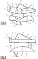
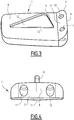
- the figures 1 and 2 show the three elements of an example of a prosthesis according to the invention, assembled on top of each other in their usual relative positions which they are supposed to occupy when the prosthesis is implanted and the patient's ankle is at rest.
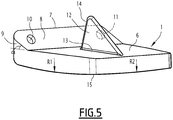
- the first element of the prosthesis is a tibial implant 1 anchored to the lower end of the patient's tibia which has been suitably shaped beforehand, and, which can be seen in isolation on the figures 3, 4 and 5 .
- the second component of the prosthesis is a talar implant 2 anchored to the upper face of the talar bone which has been suitably shaped beforehand.
- the third element of the prosthesis is an insert 3, having an upper surface 4 on which the tibial implant 1 is articulated, and a lower surface 5 on which the talar implant 2 is articulated.
- Its upper face 6 is generally flat and rectangular, but it has two particular elements.
- this shield has on its anterior edge, which corresponds to the anterior edge of the patient's tibia, a shield 7 which is intended to cover the lower anterior part of the patient's tibia.
- this shield is not vertical, but has a tibial contact face 8 with the tibia which forms an angle ⁇ with the horizontal (in other words the extension of the upper face 6 of the implant), this angle ⁇ being open towards the front of the prosthesis and being between 15 and 45 °, typically equal to 30 °.
- the anterior face 9 of the shield 7, that is to say the face opposite this inclined tibial face 8, is vertical in the example shown, as is preferable without, however, being compulsory. Such a vertical anterior face 9 increases the thickness of the shield relative to an anterior surface 9 which would be oblique, therefore increases its rigidity, and is also favorable for the efficiency of the anchoring screws.
- passages 10, 11 for the passage of bone screws (not shown). These passages 10, 11 pass through the shield 7 in an ascending direction, preferably forming an angle of 60 ° to 80 ° with the horizontal.
- the bone screws open onto the inclined tibial face 8 of the shield 7, and come to be housed in the patient's tibia, ensuring good attachment of the tibial implant 1 to the tibia. It is not necessary for the bone screws to open out perpendicularly to the posterior face 8 of the shield 7, therefore said angle that the passages 10, 11 form with the horizontal is not dependent on the value of said angle ⁇ .
- the 15-45 ° angulation ⁇ of the shield 7, ensures that the tibial implant 1 will not be tilted back and forth or vice versa during its use, and that it will remain perfectly horizontal, provided that the preliminary cutting of the tibia has been correctly done.
- This cutout is subject to the same constraints as for the implant of EP-A-1 915 975 , to which is added the conformation of the surface of the tibia on which the inclined tibial face 8 of the shield 7 comes into contact. But this conformation is achieved by a suitable cutting guide, in the same movement as the conformation of the lower face of the tibia on which the upper face 6 of the tibial implant 1 will rest.
- a suitable cutting guide in the same movement as the conformation of the lower face of the tibia on which the upper face 6 of the tibial implant 1 will rest.
- Such an example of a cutting guide will be described in more detail. far.
- This securing of the tibial implant 1 to the tibia is also ensured by a fin 12 arranged on the upper face 6 of the implant 1 and which extends, preferably over the major part of the longitudinal axis of said face 6 (that is to say of the axis which goes from the posterior part to the anterior part of the implant).
- This fin is generally in the shape of a right triangle and must fit into the patient's tibia.
- the use of fins approximately in a right-angled triangle on a tibial implant is already known in the prior art. These known fins, however, have a shape which is substantially different from that which the invention preferably comprises.
- the approximately right-angled triangle fins have the small side of the triangle that rests on the upper surface of the tibial implant, and their hypotenuse (which may, in fact, be slightly curved) faces the front of the tibia. They therefore have a relatively large height and are inserted into the medullary cavity of the tibia, previously arranged for this purpose.
- the fin 12 as shown, according to a preferred variant of the invention, on the contrary has its hypotenuse 13 which rests on the upper face 6 of the tibial implant 1.
- the small side 14 of the fin is oriented towards the front of the tibial implant 1, therefore in the direction of the shield 7.
- this fin shape 12 requires less healthy bone to be removed than conventional fins, which are narrower but have a great height.
- the tibia is therefore less weakened, which is important especially if the patient suffers from osteoporosis.
- Conventional fins are more likely to result in the unwanted formation of bony geodes.
- the fact of having the hypotenuse 13 placed on the upper surface 6 of the tibial implant 1, with the small side 14 of the fin directed towards the front of the tibia makes it possible to have both a relatively low height of the fin 12 and a large contact surface of the fin 12 with the upper surface 6 of the tibial implant 1, hence a good distribution of the forces exerted on the tibial implant 1 when walking, which is favorable to good durability of the tibial implant 1.
- the length of the hypotenuse 13 of the fin 12 represents 50% to 80%, typically 70%, of the total length of the upper face 6 of the tibial implant 1, said total length therefore including the portion on which the shield 8 is present.
- the height of the fin 12 represents 60% to 80% of the total height of the tibial implant 1, typically 2/3 of this height.
- the fin 12 has the general shape of a right triangle, but the upper angle which, as shown, may be rounded, is not necessarily strictly equal to 90 °, and may lie in a range from 80 ° to 120 °.
- the fin 12 has a width of between 2 and 3 mm, for example approximately 2.5 mm.
- a space is kept between the anterior end of the base of the fin 12 and the base of the shield 8. But this is only a variant embodiment, and it would remain in accordance with the invention. to abut the base of the fin 12 against the base of the shield 8.
- this lower surface 15 of the tibial implant 1 it must be capable of providing a possibility of articulation with the corresponding upper surface 4 of the insert 3, so as to contribute to restoring its natural movements to the patient's ankle. It is thus possible to give this lower surface 15 a convex shape substantially in a portion of a sphere, and having a radius of curvature R substantially identical to that exhibited by the upper surface 4 of the insert 3, the latter being the "negative" of the lower surface 15 of the tibial implant 1, and therefore being concave in a portion of a sphere, so as to articulate the tibial implant 1 and the insert 3 on one another in the manner of a patella. Typically, this radius R is of the order of 300 to 310 mm.
- this lower surface 15 of the tibial implant 1 is convex and does not have a single radius of curvature, but, as shown in Figure figure 5 which highlights this configuration, two different radii of curvature: a radius of curvature R1 in the antero-posterior plane and another radius of curvature R2 in the medio-lateral plane.
- R1 is greater than R1 in the example shown, but the reverse would also be possible.
- the differences between these two radii R1 and R2 must however remain small to ensure proper functioning of the joint, of the order of 1 to 5%, this percentage being calculated on the basis of R2.
- this configuration with two radii of curvature would preferably be found substantially identically on the upper surface 4 of the insert 3.
- R1 can be 305mm and R2 310mm.
- an ankle prosthesis It is customary to cover the various parts of an ankle prosthesis with hydroxyapatite, or another substance promoting bone growth, in areas where the prostheses are in contact with the patient's bone.
- Another type of surface treatment in particular shot blasting, in addition to or instead of this coating, can also contribute to this function.
- shot blasting in addition to or instead of this coating
- bone geodes can form in the coated areas when the latter have somewhat complex shapes. The inventors therefore consider it preferable not to have such a coating on the fin 12 and, in general, not to treat its surface by physical or chemical means.
- the chemical and / or physical treatment of the surface may be limited to all or part of the upper face 6 of the tibial implant 1 and also to that of the shield 8, or in general to any part of the tibial implant 1 intended to come into contact with the patient's tibia, other than the wing 12.
- the talar implant 2 will now be described in more detail.
- the articulation surfaces between the talar implant 2 and the insert 3 have corresponding shapes, and the talar implant 2 and the insert 3 can slide over each other freely in the sagittal plane, but not in the frontal plane other than in rotation, the aim of which is to keep the prosthesis in place and to avoid dislocation in the event of lateral hyperlaxity of the patient's ankle.
- the cross section of the groove 17 has a radius of curvature and the groove 17 separates the upper surface 16 of the talar implant 2 into two portions connected to each other by lines of inflection along which the direction of curvature s 'reverse. Each of these portions has the shape of a portion of a sphere.
- this preferred configuration of the talar implant 2 is distinguished by two particularities.
- its lower surface 18 is not curved, but flat. This simplifies the conformation of the talar bone, compared to the classic case where this lower surface is curved and approximately reproduces the nominal shape of the talar bone. Even in talar implants with a curved undersurface, conformation of the talar bone surface to accommodate the implant is necessary anyway, so that implantation of the talar implant according to this preferred variant of the invention does not require an additional step with respect to the most common practice. And even the flat lower surface 18 of this variant of the invention simplifies this conformation of the talar bone.
- the anchoring of the talar implant 2 in the talar bone is no longer ensured by substantially cylindrical pins, but by a flat transverse talar fin 19 inclined relative to the lower surface 18 of the talar implant. 2 at an angle ⁇ oriented towards the rear of the prosthesis and whose value is between 20 and 70 °, for example 45 ° as shown, preferably between 30 ° and 50 ° to facilitate the insertion of the winglet 19 in the talar bone.
- the vertical bulk of the fin 19 is typically 4 to 10 mm, depending on the overall size of the prosthesis which depends, of course, on the measurements of the patient.
- the width of the talar fin 19 typically corresponds to 40 to 80% of the total width of the talar implant.
- the thickness of the talar fin 19 is typically of the order of 2.5 mm.
- the inventors recommend not to treat the surface of the talar transverse fin 19 by deposition of hydroxyapatite (or equivalent) and / or shot peening, for the same reasons as those cited in connection with the longitudinal tibial fin 12.
- This treatment, s 'it is carried out, therefore, is preferably limited to all or part of the flat lower surface 18 of the talar implant 2 or, in general, to any part of the talar implant 2 intended to come into contact with the talar bone, other than the transverse fin 19.
- the upper face 4 has on its upper face 4 and its lower face 5 the characteristics of shape and dimensions which result from the respective conformations of the lower face 15 of the tibial implant 1 and of the upper face 16 of the talar implant 2 such as we have just described them.
- the upper face 4 is hollowed out with one or more radii of curvature corresponding substantially to that or those of the lower face 15 of the tibial implant, and the lower face 5 has a saddle shape which is substantially the "negative" of the saddle shape of the upper surface 16 of the talar implant 2.
- an ankle prosthesis according to the invention in its preferred variant shown, would be as follows.
- the tibial implant 1 has a substantially rectangular shape, or a slightly trapezoidal shape for which the large side is the anterior edge of the implant. Its length is 40.5 mm and its maximum width 32 mm. Its total height, including fin 12, is 15 mm. Its thickness, excluding the fin 12 and the shield 7, is approximately 5 mm (it varies due to the presence of the radii of curvature R1 and R2 of its lower face 15). The height of the shield 7 is 10.1 mm and its length is 10 mm. The angle ⁇ is 30 ° The radii R1 and R2 of the lower face 15 are respectively 310 and 315 mm.
- the fin 12 has an apex angle of 90 ° and a hypotenuse of length 27 mm.
- the talar implant 2 has a generally rectangular or trapezoidal shape, although, as shown in Figure figure 1 , its anterior and posterior edges may each have a notch at the opening of the groove 17. Its length is 38 mm and its maximum width is 29.5 mm. Its maximum height is 17 mm including fin 19 and 9 mm excluding fin, and the radius of curvature of its upper face 16 is 26.3 mm. Its minimum height excluding fin 17 (measured at the bottom of groove 17) is 5.4 mm. The radii of curvature of the upper face 16 are 29.4 mm at the level of the groove 17 and 19.5 mm on either side of the groove 17. The fin 19 forms an angle ⁇ of 45 ° with the face lower 18 of the talar implant 2, it is placed 6 mm from the anterior edge of the talar implant 2 and extends over a height of 7.7 mm.
- the insert 3 has a generally rectangular or trapezoidal shape. Its length is 26 mm and its maximum width is 28 mm. If its shape is trapezoidal, its minimum width is 24 mm. Its maximum total thickness is 10.6 mm, and its thickness, if we do not take into account the part intended to conform to the upper surface 16 of the talar implant and to penetrate into the groove 17 varies between 5.3 mm (in the central part of the insert 3) and 8.1 mm (at the anterior and posterior edges of insert 3).
- the upper face 4 of the insert 3 has curvatures which reproduce "in negative" those of the lower face 15 of the tibial implant 1 that we have given.
- the dimensions of the prosthesis according to the invention are to be adapted to the precise morphology of the patient, and can be chosen, in particular, from the previous example by modifying said dimensions homothetically.
- a particularly advantageous way of implementing the invention consists in offering it in the form of a kit comprising a series of prostheses the general dimensions of which would be different and capable of being suitable for patients of various morphologies.
- all the prostheses of the kit have on the lower faces 15 of their tibial implants 1 and on the upper faces 4 of their inserts 3 the same radius of curvature R (or the same radii of curvature R1 and R2 for the case of the figure 5 ).
- the surgeon can choose, among the elements of the various prostheses of the kit, those which seem to him best adapted to the precise morphology of the patient after the cuts of the tibia and the talar bone, being assured that two elements taken in two different prostheses will nevertheless be compatible.
- the kit can also include one or more guides and cutting tools specially designed to configure the lower end of the tibia so as to allow the establishment of the tibial implant 1 according to the invention with its shield 7. It can also include one or more other guides and cutting tools designed to configure the upper surface of the talar bone, so as to allow the placement of the talar implant 2 with lower surface 18 flat and inclined wing 19 shown in the kit.
- Cutting the lower end of the patient's tibia can be done as follows.
- a cut-out of a flat surface and substantially perpendicular to the longitudinal axis of the tibia is carried out.
- This can be carried out using a cutting guide and a cutting blade conventionally known for this purpose to achieve the placement of conventional tibial implants without an inclined shield, such as for example that described in EP-A-1 915 975 already mentioned, which has a vertical transverse stop bearing on the anterior face of the tibia.
- It comprises a plate 20 whose upper surface 21 is designed to bear on the flat surface and substantially perpendicular to the longitudinal axis of the tibia which was cut during the first cutting step, and whose lower surface 22 comprises , in the example shown, two rails 23, 24 which allow the plate to slide and to rest on a grooved spacer arranged on the talar bone, and which has the function of imposing the ligament tension which will be desired after the placement of the prosthesis, according to its thickness combined with that of the plate 20.
- AES a so-called "AES" operating technique is applied which is very comparable to that described in the document.
- EP-B-1 301 148 which relates to an ankle prosthesis in three parts of which the tibial implant, on the one hand, is devoid of the shield according to the present invention, and, on the other hand, comprises a fin in a right-angled triangle of great height whose hypotenuse faces the front of the tibia, unlike a preferred variation of the present invention.
- the rear edge of the upper face 21 of the plate 20 comprises means for assisting in positioning and maintaining the plate 20 which, in the example shown, consist of two stops 25, 26 which are made to come resting against the rear external cortex of the tibia.
- a longitudinal appendage 27 of substantially square section in the example shown.
- This appendix 27 is intended to cooperate with a plate 28 which has a through orifice 29 opening onto the anterior and posterior faces of the plate 28, and in which the appendix 27 can slide with a minimum of play.
- the angle formed by the plate 28 and the plate 20 is well determined and of permanent value (generally 90 °). It is therefore not recommended to give this appendix 27 a circular section which would easily allow it to rotate inside the orifice 29 during the installation and use of the cutting guide.
- the position of the plate 28 along the appendix 27 can be fixed, as shown, by means of transverse holes 30, 31, 32, 33 formed in the appendix 27 and a transverse hole 34 formed in the plate. 28 and passing through the longitudinal hole 29.
- a pin (not shown) or any other functionally similar locking device can thus be accommodated in the transverse hole 34 of the plate 28 by passing through one of the transverse holes 30-33 of the plate 28. 'appendix 27.
- the fixing of the cutting guide to the tibia is ensured, for example by means of nails passing through longitudinal holes 35 located in the upper part of the tibia. plate 28.
- the plate 28 has a transverse slot 36 which extends between the anterior face and the posterior face of the plate 28, and which is inclined at an angle equal to the angle ⁇ with respect to the horizontal.
- This slot 36 has a width and thickness sufficient to allow a conventional type cutting blade to pass through and guide that the surgeon can introduce therein, in order to cut the tibia for the reception of the shield 7.
- the plate 28 also comprises a vertical slot 37 located in the transverse median plane of the plate 28. This slot 37 is dimensioned to allow the introduction of a cutting blade for provide an orifice in the tibia into which the fin 12 can be inserted when placing the tibial implant 1. If several fins 12 are provided on the tibial implant 1, it will of course be necessary to provide a similar number of slots 37 at locations corresponding to those of fins 12.
- the surgeon cuts the talar bone which will allow it to receive a talar implant 2 according to the invention.
- this cutting tool must be able to provide a flat upper surface on the talar bone, if the lower surface 18 of the talar implant 2 is flat, as in the preferred example shown. This can be achieved, for example, using a cutting guide comparable to that described in the document WO-A-01/89427 .
- these cutting guides or at least some of them in particular the one intended for the preparation of the tibia for the reception of the tibial implant 1 according to the invention and of its shield 7 which is specific to implantation of the ankle prosthesis according to the invention can advantageously be included in a kit including the components of the ankle prosthesis.
- This kit may also include cutting tools and means for securing the cutting guides to the corresponding bones of the patient, especially if such cutting tools and securing means are not of types commonly available in isolation from surgeons.
Landscapes
- Health & Medical Sciences (AREA)
- Life Sciences & Earth Sciences (AREA)
- Orthopedic Medicine & Surgery (AREA)
- Animal Behavior & Ethology (AREA)
- Surgery (AREA)
- Engineering & Computer Science (AREA)
- Biomedical Technology (AREA)
- Heart & Thoracic Surgery (AREA)
- Veterinary Medicine (AREA)
- Oral & Maxillofacial Surgery (AREA)
- Public Health (AREA)
- General Health & Medical Sciences (AREA)
- Cardiology (AREA)
- Vascular Medicine (AREA)
- Dentistry (AREA)
- Nuclear Medicine, Radiotherapy & Molecular Imaging (AREA)
- Transplantation (AREA)
- Medical Informatics (AREA)
- Molecular Biology (AREA)
- Prostheses (AREA)
Claims (13)
- Knöchelprothese, umfassend ein Tibiaimplantat (1), ein Talusimplantat (2) und einen Einsatz (3), an dem die Implantate (1, 2) angelenkt sind, wobei:- die obere Fläche (6) des Tibiaimplantats (1) mindestens eine Rippe (12) zur Verankerung des Tibiaimplantats (1) in der Tibia des Patienten umfasst und die untere Fläche (15) des Tibiaimplantats (1) eine Gelenkfläche mit der oberen Fläche (4) des Einsatzes (3) ist;- die untere Fläche (18) des Talusimplantats (2) Einrichtungen zur Verankerung an dem Talusknochen des Patienten umfasst, und die obere Fläche (16) des Talusimplantats (2) eine Gelenkfläche mit der unteren Fläche (5) des Einsatzes (3) ist, wobei die Gelenkfläche sattelförmig ist und eine mittlere Längsnut (17) umfasst, in der der Einsatz (3) in Längsrichtung verschiebbar und in Querrichtung drehbar ist;dadurch gekennzeichnet, dass die obere Fläche (6) des Tibiaimplantats (1) an ihrem vorderen Rand eine Schale (7) aufweist, die dazu bestimmt ist, den unteren vorderen Abschnitt der Tibia des Patienten abzudecken und deren Tibiafläche (8) geneigt ist und mit der Horizontalen einen Winkel (α) zwischen 15° und 45° bildet, und dass in dieser Schale (7) Durchgänge (10, 11) für Knochenschrauben angeordnet sind, die die Schale (7) aufsteigend durchdringen und an ihrer geneigten Tibiafläche (8) münden.
- Knöchelprothese nach Anspruch 1, dadurch gekennzeichnet, dass die untere Fläche (15) des Tibiaimplantats (1) konvex und teilweise kugelförmig ist und einen Krümmungsradius (R) aufweist, und dass die obere Fläche (4) des Einsatzes (3) konkav und teilweise kugelförmig ist und einen Krümmungsradius aufweist, der gleich dem Krümmungsradius (R) der unteren Fläche (15) des Tibiaimplantats (1) ist.
- Knöchelprothese nach Anspruch 1, dadurch gekennzeichnet, dass die untere Fläche (15) des Tibiaimplantats (1) konvex ist und einen ersten Krümmungsradius (R1) in der anterior-posterioren Ebene der Prothese und einen zweiten Krümmungsradius (R2) in der medio-lateralen Ebene der Prothese aufweist, und dass die obere Fläche (4) des Einsatzes (3) konkav ist und die gleichen Krümmungsradien (R1, R2) wie die untere Fläche (15) des Tibiaimplantats (1) aufweist, wobei der Unterschied zwischen dem ersten (R1) und dem zweiten (R2) Krümmungsradius zwischen 1 und 5 % des zweiten Krümmungsradius (R2) ist.
- Knöchelprothese nach einem der Ansprüche 1 bis 3, dadurch gekennzeichnet, dass die Einrichtungen zur Verankerung des Talusimplantats mindestens eine Querrippe (19) umfassen, die in Bezug auf die untere Fläche (18) des Talusimplantats (2) um einen Winkel (β) geneigt ist, der zu der Rückseite der Prothese gerichtet ist und dessen Wert zwischen 20 und 70°, vorzugsweise zwischen 30 und 50°, ist.
- Knöchelprothese nach Anspruch 4, dadurch gekennzeichnet, dass ihr Talusimplantat (2) mindestens zwei nebeneinander angeordnete Querrippen (19) umfasst.
- Knöchelprothese nach Anspruch 4 oder 5, dadurch gekennzeichnet, dass die Breite der Querrippe (19) oder die Summe der Breiten der nebeneinander angeordneten Querrippen (19) zwischen 40 und 80 % der Breite des Talusimplantats (2) ist.
- Knöchelprothese nach einem der Ansprüche 1 bis 6, dadurch gekennzeichnet, dass die mindestens eine Rippe (12) zur Verankerung des Tibiaimplantats (1) in der Tibia des Patienten im Wesentlichen in der Form eines rechtwinkligen Dreiecks ist, dessen Hypotenuse (13) auf der oberen Fläche (6) des Tibiaimplantats (1) aufliegt und dessen kurze Seite (14) zu der Vorderseite des Tibiaimplantats (1) ausgerichtet ist.
- Knöchelprothese nach Anspruch 7, dadurch gekennzeichnet, dass die Länge der Hypotenuse (13) der Tibiarippe (12) zwischen 50 % und 80 % der Gesamtlänge der oberen Fläche (6) des Tibiaimplantats (1) ist.
- Knöchelprothese nach Anspruch 7 oder 8, dadurch gekennzeichnet, dass der obere Winkel der Tibiarippe (12) zwischen 80° und 120° ist.
- Knöchelprothese nach einem der Ansprüche 1 bis 9, dadurch gekennzeichnet, dass die mindestens eine Verankerungsrippe (12) des Tibiaimplantats (1) und die Einrichtungen zur Verankerung des Talusimplantats (2) keiner Oberflächenbehandlung zur Förderung des Knochenwachstums unterzogen wurden, während andere Abschnitte der Implantate (1, 2), die dazu bestimmt sind, mit der Tibia oder dem Talarknochen in Kontakt zu sein, einer solchen Oberflächenbehandlung unterzogen wurden.
- Kit, umfassend eine Vielzahl von Knöchelprothesen nach einem der Ansprüche 1 bis 10, dadurch gekennzeichnet, dass die Prothesen unterschiedliche Abmessungen aufweisen, aber alle identische Krümmungsradien (R; R1, R2) an den Unterseiten (15) ihrer Tibiaimplantate (1) und an den oberen Flächen (4) ihrer Einsätze (3) aufweisen.
- Kit, umfassend mindestens eine Knöchelprothese nach einem der Ansprüche 1 bis 10, dadurch gekennzeichnet, dass sie auch eine Schneidführung für die Vorbereitung der Tibia zur Aufnahme der Schale (7) des Tibiaimplantats (1) nach Anspruch 1 umfasst.
- Kit nach Anspruch 11, dadurch gekennzeichnet, dass es auch eine Schneidführung für die Vorbereitung der Tibia für die Aufnahme der Schale (7) des Tibiaimplantats (1) nach Anspruch 1 umfasst.
Applications Claiming Priority (2)
| Application Number | Priority Date | Filing Date | Title |
|---|---|---|---|
| FR1758993A FR3071400B1 (fr) | 2017-09-28 | 2017-09-28 | Prothese de cheville comportant un implant talien, un implant tibial et un insert, kit incluant au moins une telle prothese, et guide de coupe pour la mise en place de l'implant tibial |
| PCT/EP2018/076500 WO2019063807A1 (fr) | 2017-09-28 | 2018-09-28 | Prothèse de cheville comportant un implant talien, un implant tibial et un insert, et kit incluant au moins une telle prothèse |
Publications (2)
| Publication Number | Publication Date |
|---|---|
| EP3687455A1 EP3687455A1 (de) | 2020-08-05 |
| EP3687455B1 true EP3687455B1 (de) | 2021-11-24 |
Family
ID=60923633
Family Applications (1)
| Application Number | Title | Priority Date | Filing Date |
|---|---|---|---|
| EP18773488.4A Active EP3687455B1 (de) | 2017-09-28 | 2018-09-28 | Knöchelprothese mit einem talusimplantat, einem tibiaimplantat und einem einsatz sowie kit mit mindestens einer solchen prothese |
Country Status (6)
| Country | Link |
|---|---|
| US (1) | US11318023B2 (de) |
| EP (1) | EP3687455B1 (de) |
| JP (1) | JP7250024B2 (de) |
| ES (1) | ES2907782T3 (de) |
| FR (1) | FR3071400B1 (de) |
| WO (1) | WO2019063807A1 (de) |
Families Citing this family (9)
| Publication number | Priority date | Publication date | Assignee | Title |
|---|---|---|---|---|
| AU2019302325B2 (en) | 2018-04-24 | 2024-05-02 | Paragon 28, Inc. | Implants and methods of use and assembly |
| EP3893766A4 (de) * | 2018-12-13 | 2022-11-30 | Paragon 28, Inc. | Instrumente, führungen und zugehörige verfahren für knöcheltotalprothese |
| US12108959B2 (en) | 2019-05-29 | 2024-10-08 | Wright Medical Technology, Inc. | Preparing a tibia for receiving tibial implant component of a replacement ankle |
| USD920515S1 (en) | 2020-01-08 | 2021-05-25 | Restor3D, Inc. | Spinal implant |
| USD920517S1 (en) | 2020-01-08 | 2021-05-25 | Restor3D, Inc. | Osteotomy wedge |
| FR3106271B1 (fr) * | 2020-01-22 | 2021-12-24 | In2Bones | Composant implantable a moyen d’ancrage ameliore pour prothese de cheville et prothese de cheville comprenant un tel composant |
| WO2022183150A1 (en) * | 2021-02-24 | 2022-09-01 | Wright Medical Technology, Inc. | Implant peg with multiple components |
| US11806028B1 (en) | 2022-10-04 | 2023-11-07 | Restor3D, Inc. | Surgical guides and processes for producing and using the same |
| US11960266B1 (en) | 2023-08-23 | 2024-04-16 | Restor3D, Inc. | Patient-specific medical devices and additive manufacturing processes for producing the same |
Family Cites Families (21)
| Publication number | Priority date | Publication date | Assignee | Title |
|---|---|---|---|---|
| FR2759900B1 (fr) * | 1997-02-26 | 1999-06-11 | Sem Sa | Systeme pour le remplacement de l'articulation de la cheville |
| IT1310371B1 (it) * | 1999-05-13 | 2002-02-13 | Ist Ortopedici Rizzoli | Dispositivo di protesi per articolazione umana, in particolare perarticolazione della tibotarsica e relativo metodo di impianto. |
| FR2800601B1 (fr) * | 1999-11-05 | 2002-01-04 | Europ Foot Platform | Prothese de cheville |
| FR2808994B1 (fr) | 2000-05-22 | 2003-03-21 | Transysteme Sarl | Prothese d'articulation |
| EP1809209A2 (de) * | 2004-08-19 | 2007-07-25 | Kinetikos Medical Incorporated | Modulare sprunggelenktotalprothese, -vorrichtungen, -systeme und -verfahren sowie systeme und verfahren zur knochenresektion und prothesenimplantation |
| FR2879436B1 (fr) * | 2004-12-22 | 2007-03-09 | Ldr Medical | Prothese de disque intervertebral |
| US20060247788A1 (en) * | 2005-03-31 | 2006-11-02 | The Regents Of The University Of California | Total ankle arthroplasty |
| FR2896404B1 (fr) * | 2006-01-24 | 2008-02-29 | Tornier Sas | Ensemble d'instrumentation chirurgicale pour poser une prothese de cheville |
| US7662183B2 (en) * | 2006-01-24 | 2010-02-16 | Timothy Haines | Dynamic spinal implants incorporating cartilage bearing graft material |
| FR2902315B1 (fr) * | 2006-06-20 | 2008-09-12 | Abbott Spine Sa | Implant intervertebral distractable |
| EP2063817A4 (de) * | 2006-09-15 | 2012-04-18 | Pioneer Surgical Technology Inc | Gelenkarthroplastie-vorrichtung mit beweglichen elementen |
| FR2907657B1 (fr) | 2006-10-26 | 2009-07-10 | Newdeal Soc Par Actions Simpli | Prothese de cheville avec reglage de position neutre |
| US9278006B2 (en) * | 2006-10-26 | 2016-03-08 | European Foot Platform Sc | Ankle prosthesis with neutral position adjustment |
| US20110035019A1 (en) * | 2009-07-09 | 2011-02-10 | Wright State University | Total ankle replacement system |
| WO2011008739A2 (en) * | 2009-07-14 | 2011-01-20 | Medicinelodge, Inc. Dba Imds Co-Innovation | Joint arthrodesis and arthroplasty |
| US9492281B2 (en) * | 2010-02-19 | 2016-11-15 | European Foot Platform Sc | Ankle prosthesis with simplified adjustment |
| US8303667B2 (en) * | 2010-03-02 | 2012-11-06 | Alastair Younger | Fastening system for prostheses |
| EP2363087B1 (de) * | 2010-03-04 | 2014-05-07 | Alastair Younger | Befestigungssystem für Prothesen |
| WO2015175560A1 (en) * | 2014-05-12 | 2015-11-19 | Integra Lifesciences Corporation | Total ankle replacement prosthesis |
| CA2889726C (en) * | 2015-01-12 | 2018-06-26 | Wright Medical Technology, Inc. | Targeted screw for talar dome fixation |
| FR3070593A1 (fr) * | 2017-09-05 | 2019-03-08 | In2Bones | Prothese de cheville amelioree |
-
2017
- 2017-09-28 FR FR1758993A patent/FR3071400B1/fr not_active Expired - Fee Related
-
2018
- 2018-09-28 JP JP2020539139A patent/JP7250024B2/ja active Active
- 2018-09-28 ES ES18773488T patent/ES2907782T3/es active Active
- 2018-09-28 WO PCT/EP2018/076500 patent/WO2019063807A1/fr unknown
- 2018-09-28 US US16/651,753 patent/US11318023B2/en active Active
- 2018-09-28 EP EP18773488.4A patent/EP3687455B1/de active Active
Also Published As
| Publication number | Publication date |
|---|---|
| EP3687455A1 (de) | 2020-08-05 |
| FR3071400B1 (fr) | 2019-10-04 |
| US20200330238A1 (en) | 2020-10-22 |
| FR3071400A1 (fr) | 2019-03-29 |
| WO2019063807A1 (fr) | 2019-04-04 |
| US11318023B2 (en) | 2022-05-03 |
| JP7250024B2 (ja) | 2023-03-31 |
| JP2020535933A (ja) | 2020-12-10 |
| ES2907782T3 (es) | 2022-04-26 |
Similar Documents
| Publication | Publication Date | Title |
|---|---|---|
| EP3687455B1 (de) | Knöchelprothese mit einem talusimplantat, einem tibiaimplantat und einem einsatz sowie kit mit mindestens einer solchen prothese | |
| EP3449876B1 (de) | Verbesserte knöchelprothese | |
| EP2547291B1 (de) | Knieprothese mit gemischter meniskusscheibe | |
| EP1813230B1 (de) | Chirurgisches Instrumentenkit zum Einbringen einer Knöchelprothese. | |
| EP1529493B1 (de) | Implantierbare Orthese und chirurgischer Satz für eine Arthrodese des Knies | |
| CA2726034C (fr) | Prothese totale de genou | |
| FR3050927A1 (fr) | Implant vertebral et insert pour implant vertebral | |
| FR2799639A1 (fr) | Prothese de disque intervertebral a faces dentees | |
| WO2010079288A1 (fr) | Implant orthopedique pour arthroplastie digitale | |
| FR2893838A1 (fr) | Prothese de disque intervertebral et instrumentation d'insertion de la prothese entre les vertebres | |
| FR2926719A1 (fr) | Ensemble compose d'une embase tibiale et d'un insert tibial et prothese comprenant un tel ensemble | |
| FR2862866A1 (fr) | Prothese discale intervertebrale postero-laterale | |
| EP2440161A1 (de) | Intervertebrales implantat und instrument zu seiner platzierung | |
| FR2951366A1 (fr) | Materiel prothetique pour remplacer au moins une partie de la glene radiale d'un radius | |
| EP1799158A2 (de) | Komplette knieprothese und elemente zur herstellund dieser prothese | |
| EP3854355B1 (de) | Implantierbare komponente mit verbesserter verankerung für knöchelprothese und eine solche komponente umfassende knöchelprothese | |
| FR2945436A1 (fr) | Instrumentation chirurgicale de distraction osseuse de l'epaule | |
| FR2630639A1 (fr) | Dispositif de prothese partielle du genou | |
| FR2630640A1 (fr) | Dispositif de prothese partielle du genou | |
| FR3006167A1 (fr) | Perfectionnement aux protheses totales de genou et a leur procede de montage | |
| EP2617394B1 (de) | Tibialimplantat für monokondyläre Kniegelenprothese | |
| EP1543802A2 (de) | Stabilisierte Knieprothese mit drehbarem Tibialager | |
| FR2959410A1 (fr) | Prothese de genou posterostabilisee. | |
| FR2742651A1 (fr) | Prothese du genou unicompartimentale | |
| FR2846875A1 (fr) | Embase tibiale mobile en rotation asymetrique pour prothese de genou |
Legal Events
| Date | Code | Title | Description |
|---|---|---|---|
| STAA | Information on the status of an ep patent application or granted ep patent |
Free format text: STATUS: UNKNOWN |
|
| STAA | Information on the status of an ep patent application or granted ep patent |
Free format text: STATUS: THE INTERNATIONAL PUBLICATION HAS BEEN MADE |
|
| PUAI | Public reference made under article 153(3) epc to a published international application that has entered the european phase |
Free format text: ORIGINAL CODE: 0009012 |
|
| STAA | Information on the status of an ep patent application or granted ep patent |
Free format text: STATUS: REQUEST FOR EXAMINATION WAS MADE |
|
| 17P | Request for examination filed |
Effective date: 20200427 |
|
| AK | Designated contracting states |
Kind code of ref document: A1 Designated state(s): AL AT BE BG CH CY CZ DE DK EE ES FI FR GB GR HR HU IE IS IT LI LT LU LV MC MK MT NL NO PL PT RO RS SE SI SK SM TR |
|
| AX | Request for extension of the european patent |
Extension state: BA ME |
|
| RIN1 | Information on inventor provided before grant (corrected) |
Inventor name: LEONARDI, CHRISTIAN Inventor name: OLIVERA, FRANCK Inventor name: ASENCIO, JOSEPH-GUY Inventor name: DI SCHINO, MARION Inventor name: CALAMEL, LIONEL |
|
| DAV | Request for validation of the european patent (deleted) | ||
| DAX | Request for extension of the european patent (deleted) | ||
| GRAP | Despatch of communication of intention to grant a patent |
Free format text: ORIGINAL CODE: EPIDOSNIGR1 |
|
| STAA | Information on the status of an ep patent application or granted ep patent |
Free format text: STATUS: GRANT OF PATENT IS INTENDED |
|
| RIC1 | Information provided on ipc code assigned before grant |
Ipc: A61F 2/42 20060101AFI20210525BHEP Ipc: A61B 17/17 20060101ALI20210525BHEP Ipc: A61B 17/86 20060101ALI20210525BHEP Ipc: A61F 2/30 20060101ALI20210525BHEP |
|
| INTG | Intention to grant announced |
Effective date: 20210629 |
|
| GRAA | (expected) grant |
Free format text: ORIGINAL CODE: 0009210 |
|
| STAA | Information on the status of an ep patent application or granted ep patent |
Free format text: STATUS: THE PATENT HAS BEEN GRANTED |
|
| GRAS | Grant fee paid |
Free format text: ORIGINAL CODE: EPIDOSNIGR3 |
|
| AK | Designated contracting states |
Kind code of ref document: B1 Designated state(s): AL AT BE BG CH CY CZ DE DK EE ES FI FR GB GR HR HU IE IS IT LI LT LU LV MC MK MT NL NO PL PT RO RS SE SI SK SM TR |
|
| REG | Reference to a national code |
Ref country code: GB Ref legal event code: FG4D Free format text: NOT ENGLISH |
|
| REG | Reference to a national code |
Ref country code: AT Ref legal event code: REF Ref document number: 1449282 Country of ref document: AT Kind code of ref document: T Effective date: 20211215 |
|
| REG | Reference to a national code |
Ref country code: DE Ref legal event code: R096 Ref document number: 602018027211 Country of ref document: DE |
|
| REG | Reference to a national code |
Ref country code: IE Ref legal event code: FG4D Free format text: LANGUAGE OF EP DOCUMENT: FRENCH |
|
| REG | Reference to a national code |
Ref country code: LT Ref legal event code: MG9D |
|
| REG | Reference to a national code |
Ref country code: NL Ref legal event code: MP Effective date: 20211124 |
|
| REG | Reference to a national code |
Ref country code: AT Ref legal event code: MK05 Ref document number: 1449282 Country of ref document: AT Kind code of ref document: T Effective date: 20211124 |
|
| REG | Reference to a national code |
Ref country code: ES Ref legal event code: FG2A Ref document number: 2907782 Country of ref document: ES Kind code of ref document: T3 Effective date: 20220426 |
|
| PG25 | Lapsed in a contracting state [announced via postgrant information from national office to epo] |
Ref country code: RS Free format text: LAPSE BECAUSE OF FAILURE TO SUBMIT A TRANSLATION OF THE DESCRIPTION OR TO PAY THE FEE WITHIN THE PRESCRIBED TIME-LIMIT Effective date: 20211124 Ref country code: LT Free format text: LAPSE BECAUSE OF FAILURE TO SUBMIT A TRANSLATION OF THE DESCRIPTION OR TO PAY THE FEE WITHIN THE PRESCRIBED TIME-LIMIT Effective date: 20211124 Ref country code: FI Free format text: LAPSE BECAUSE OF FAILURE TO SUBMIT A TRANSLATION OF THE DESCRIPTION OR TO PAY THE FEE WITHIN THE PRESCRIBED TIME-LIMIT Effective date: 20211124 Ref country code: BG Free format text: LAPSE BECAUSE OF FAILURE TO SUBMIT A TRANSLATION OF THE DESCRIPTION OR TO PAY THE FEE WITHIN THE PRESCRIBED TIME-LIMIT Effective date: 20220224 Ref country code: AT Free format text: LAPSE BECAUSE OF FAILURE TO SUBMIT A TRANSLATION OF THE DESCRIPTION OR TO PAY THE FEE WITHIN THE PRESCRIBED TIME-LIMIT Effective date: 20211124 |
|
| PG25 | Lapsed in a contracting state [announced via postgrant information from national office to epo] |
Ref country code: IS Free format text: LAPSE BECAUSE OF FAILURE TO SUBMIT A TRANSLATION OF THE DESCRIPTION OR TO PAY THE FEE WITHIN THE PRESCRIBED TIME-LIMIT Effective date: 20220324 Ref country code: SE Free format text: LAPSE BECAUSE OF FAILURE TO SUBMIT A TRANSLATION OF THE DESCRIPTION OR TO PAY THE FEE WITHIN THE PRESCRIBED TIME-LIMIT Effective date: 20211124 Ref country code: PT Free format text: LAPSE BECAUSE OF FAILURE TO SUBMIT A TRANSLATION OF THE DESCRIPTION OR TO PAY THE FEE WITHIN THE PRESCRIBED TIME-LIMIT Effective date: 20220324 Ref country code: PL Free format text: LAPSE BECAUSE OF FAILURE TO SUBMIT A TRANSLATION OF THE DESCRIPTION OR TO PAY THE FEE WITHIN THE PRESCRIBED TIME-LIMIT Effective date: 20211124 Ref country code: NO Free format text: LAPSE BECAUSE OF FAILURE TO SUBMIT A TRANSLATION OF THE DESCRIPTION OR TO PAY THE FEE WITHIN THE PRESCRIBED TIME-LIMIT Effective date: 20220224 Ref country code: NL Free format text: LAPSE BECAUSE OF FAILURE TO SUBMIT A TRANSLATION OF THE DESCRIPTION OR TO PAY THE FEE WITHIN THE PRESCRIBED TIME-LIMIT Effective date: 20211124 Ref country code: LV Free format text: LAPSE BECAUSE OF FAILURE TO SUBMIT A TRANSLATION OF THE DESCRIPTION OR TO PAY THE FEE WITHIN THE PRESCRIBED TIME-LIMIT Effective date: 20211124 Ref country code: HR Free format text: LAPSE BECAUSE OF FAILURE TO SUBMIT A TRANSLATION OF THE DESCRIPTION OR TO PAY THE FEE WITHIN THE PRESCRIBED TIME-LIMIT Effective date: 20211124 Ref country code: GR Free format text: LAPSE BECAUSE OF FAILURE TO SUBMIT A TRANSLATION OF THE DESCRIPTION OR TO PAY THE FEE WITHIN THE PRESCRIBED TIME-LIMIT Effective date: 20220225 |
|
| PG25 | Lapsed in a contracting state [announced via postgrant information from national office to epo] |
Ref country code: SM Free format text: LAPSE BECAUSE OF FAILURE TO SUBMIT A TRANSLATION OF THE DESCRIPTION OR TO PAY THE FEE WITHIN THE PRESCRIBED TIME-LIMIT Effective date: 20211124 Ref country code: SK Free format text: LAPSE BECAUSE OF FAILURE TO SUBMIT A TRANSLATION OF THE DESCRIPTION OR TO PAY THE FEE WITHIN THE PRESCRIBED TIME-LIMIT Effective date: 20211124 Ref country code: RO Free format text: LAPSE BECAUSE OF FAILURE TO SUBMIT A TRANSLATION OF THE DESCRIPTION OR TO PAY THE FEE WITHIN THE PRESCRIBED TIME-LIMIT Effective date: 20211124 Ref country code: EE Free format text: LAPSE BECAUSE OF FAILURE TO SUBMIT A TRANSLATION OF THE DESCRIPTION OR TO PAY THE FEE WITHIN THE PRESCRIBED TIME-LIMIT Effective date: 20211124 Ref country code: DK Free format text: LAPSE BECAUSE OF FAILURE TO SUBMIT A TRANSLATION OF THE DESCRIPTION OR TO PAY THE FEE WITHIN THE PRESCRIBED TIME-LIMIT Effective date: 20211124 Ref country code: CZ Free format text: LAPSE BECAUSE OF FAILURE TO SUBMIT A TRANSLATION OF THE DESCRIPTION OR TO PAY THE FEE WITHIN THE PRESCRIBED TIME-LIMIT Effective date: 20211124 |
|
| REG | Reference to a national code |
Ref country code: DE Ref legal event code: R097 Ref document number: 602018027211 Country of ref document: DE |
|
| PLBE | No opposition filed within time limit |
Free format text: ORIGINAL CODE: 0009261 |
|
| STAA | Information on the status of an ep patent application or granted ep patent |
Free format text: STATUS: NO OPPOSITION FILED WITHIN TIME LIMIT |
|
| PG25 | Lapsed in a contracting state [announced via postgrant information from national office to epo] |
Ref country code: AL Free format text: LAPSE BECAUSE OF FAILURE TO SUBMIT A TRANSLATION OF THE DESCRIPTION OR TO PAY THE FEE WITHIN THE PRESCRIBED TIME-LIMIT Effective date: 20211124 |
|
| 26N | No opposition filed |
Effective date: 20220825 |
|
| PG25 | Lapsed in a contracting state [announced via postgrant information from national office to epo] |
Ref country code: SI Free format text: LAPSE BECAUSE OF FAILURE TO SUBMIT A TRANSLATION OF THE DESCRIPTION OR TO PAY THE FEE WITHIN THE PRESCRIBED TIME-LIMIT Effective date: 20211124 |
|
| GBPC | Gb: european patent ceased through non-payment of renewal fee |
Effective date: 20220928 |
|
| PG25 | Lapsed in a contracting state [announced via postgrant information from national office to epo] |
Ref country code: LU Free format text: LAPSE BECAUSE OF NON-PAYMENT OF DUE FEES Effective date: 20220928 |
|
| PG25 | Lapsed in a contracting state [announced via postgrant information from national office to epo] |
Ref country code: IE Free format text: LAPSE BECAUSE OF NON-PAYMENT OF DUE FEES Effective date: 20220928 |
|
| PG25 | Lapsed in a contracting state [announced via postgrant information from national office to epo] |
Ref country code: GB Free format text: LAPSE BECAUSE OF NON-PAYMENT OF DUE FEES Effective date: 20220928 |
|
| PGFP | Annual fee paid to national office [announced via postgrant information from national office to epo] |
Ref country code: MC Payment date: 20230822 Year of fee payment: 6 Ref country code: IT Payment date: 20230911 Year of fee payment: 6 |
|
| PGFP | Annual fee paid to national office [announced via postgrant information from national office to epo] |
Ref country code: FR Payment date: 20230829 Year of fee payment: 6 Ref country code: DE Payment date: 20230911 Year of fee payment: 6 Ref country code: BE Payment date: 20230914 Year of fee payment: 6 |
|
| PGFP | Annual fee paid to national office [announced via postgrant information from national office to epo] |
Ref country code: ES Payment date: 20231006 Year of fee payment: 6 |
|
| PGFP | Annual fee paid to national office [announced via postgrant information from national office to epo] |
Ref country code: CH Payment date: 20231001 Year of fee payment: 6 |
|
| PG25 | Lapsed in a contracting state [announced via postgrant information from national office to epo] |
Ref country code: CY Free format text: LAPSE BECAUSE OF FAILURE TO SUBMIT A TRANSLATION OF THE DESCRIPTION OR TO PAY THE FEE WITHIN THE PRESCRIBED TIME-LIMIT Effective date: 20211124 |
|
| PG25 | Lapsed in a contracting state [announced via postgrant information from national office to epo] |
Ref country code: MK Free format text: LAPSE BECAUSE OF FAILURE TO SUBMIT A TRANSLATION OF THE DESCRIPTION OR TO PAY THE FEE WITHIN THE PRESCRIBED TIME-LIMIT Effective date: 20211124 Ref country code: HU Free format text: LAPSE BECAUSE OF FAILURE TO SUBMIT A TRANSLATION OF THE DESCRIPTION OR TO PAY THE FEE WITHIN THE PRESCRIBED TIME-LIMIT; INVALID AB INITIO Effective date: 20180928 |
|
| PG25 | Lapsed in a contracting state [announced via postgrant information from national office to epo] |
Ref country code: MT Free format text: LAPSE BECAUSE OF FAILURE TO SUBMIT A TRANSLATION OF THE DESCRIPTION OR TO PAY THE FEE WITHIN THE PRESCRIBED TIME-LIMIT Effective date: 20211124 |