EP1543802A2 - Stabilisierte Knieprothese mit drehbarem Tibialager - Google Patents
Stabilisierte Knieprothese mit drehbarem Tibialager Download PDFInfo
- Publication number
- EP1543802A2 EP1543802A2 EP04356189A EP04356189A EP1543802A2 EP 1543802 A2 EP1543802 A2 EP 1543802A2 EP 04356189 A EP04356189 A EP 04356189A EP 04356189 A EP04356189 A EP 04356189A EP 1543802 A2 EP1543802 A2 EP 1543802A2
- Authority
- EP
- European Patent Office
- Prior art keywords
- insert
- tibial
- curvature
- knee prosthesis
- radius
- Prior art date
- Legal status (The legal status is an assumption and is not a legal conclusion. Google has not performed a legal analysis and makes no representation as to the accuracy of the status listed.)
- Withdrawn
Links
Images


Classifications
-
- A—HUMAN NECESSITIES
- A61—MEDICAL OR VETERINARY SCIENCE; HYGIENE
- A61F—FILTERS IMPLANTABLE INTO BLOOD VESSELS; PROSTHESES; DEVICES PROVIDING PATENCY TO, OR PREVENTING COLLAPSING OF, TUBULAR STRUCTURES OF THE BODY, e.g. STENTS; ORTHOPAEDIC, NURSING OR CONTRACEPTIVE DEVICES; FOMENTATION; TREATMENT OR PROTECTION OF EYES OR EARS; BANDAGES, DRESSINGS OR ABSORBENT PADS; FIRST-AID KITS
- A61F2/00—Filters implantable into blood vessels; Prostheses, i.e. artificial substitutes or replacements for parts of the body; Appliances for connecting them with the body; Devices providing patency to, or preventing collapsing of, tubular structures of the body, e.g. stents
- A61F2/02—Prostheses implantable into the body
- A61F2/30—Joints
- A61F2/38—Joints for elbows or knees
- A61F2/3868—Joints for elbows or knees with sliding tibial bearing
-
- A—HUMAN NECESSITIES
- A61—MEDICAL OR VETERINARY SCIENCE; HYGIENE
- A61F—FILTERS IMPLANTABLE INTO BLOOD VESSELS; PROSTHESES; DEVICES PROVIDING PATENCY TO, OR PREVENTING COLLAPSING OF, TUBULAR STRUCTURES OF THE BODY, e.g. STENTS; ORTHOPAEDIC, NURSING OR CONTRACEPTIVE DEVICES; FOMENTATION; TREATMENT OR PROTECTION OF EYES OR EARS; BANDAGES, DRESSINGS OR ABSORBENT PADS; FIRST-AID KITS
- A61F2/00—Filters implantable into blood vessels; Prostheses, i.e. artificial substitutes or replacements for parts of the body; Appliances for connecting them with the body; Devices providing patency to, or preventing collapsing of, tubular structures of the body, e.g. stents
- A61F2/02—Prostheses implantable into the body
- A61F2/30—Joints
- A61F2/38—Joints for elbows or knees
- A61F2/3886—Joints for elbows or knees for stabilising knees against anterior or lateral dislocations
-
- A—HUMAN NECESSITIES
- A61—MEDICAL OR VETERINARY SCIENCE; HYGIENE
- A61F—FILTERS IMPLANTABLE INTO BLOOD VESSELS; PROSTHESES; DEVICES PROVIDING PATENCY TO, OR PREVENTING COLLAPSING OF, TUBULAR STRUCTURES OF THE BODY, e.g. STENTS; ORTHOPAEDIC, NURSING OR CONTRACEPTIVE DEVICES; FOMENTATION; TREATMENT OR PROTECTION OF EYES OR EARS; BANDAGES, DRESSINGS OR ABSORBENT PADS; FIRST-AID KITS
- A61F2/00—Filters implantable into blood vessels; Prostheses, i.e. artificial substitutes or replacements for parts of the body; Appliances for connecting them with the body; Devices providing patency to, or preventing collapsing of, tubular structures of the body, e.g. stents
- A61F2/02—Prostheses implantable into the body
- A61F2/30—Joints
- A61F2/38—Joints for elbows or knees
- A61F2/3877—Patellae or trochleae
Definitions
- the present invention relates to joint prostheses and relates more particularly, the field of knee prostheses.
- Knee prostheses should include artificial joint systems to replace the natural joint formed by the epiphyseal conformation lower femur, by the complementary high epiphyseal conformation of the tibia, by the patellofemoral element.
- total prostheses so-called related, in the sense that they make intervene two complementary pieces that are joined by a joint system material, such as at least one axis, constituting the artificial pivoting system materializing the knee joint in a direction perpendicular to the sagittal plane or anteroposterior.
- prostheses which are constituted, by opposition to the previous ones, based on two elements, respectively adaptable on the epiphyses of the femur and upper tibia, to cooperate by relative sliding by being maintained in surface contact through, inter alia, lateral ligaments internal and external, without the presence of a link of articulation material between these two elements.
- US Pat. No. 5,011,496 has proposed a total knee prosthesis which comprises a U-shaped femoral prosthetic element delimiting a nesting housing of the resected epiphyseal portion of a femur and comprising an anterior portion defining a trochlea, by its front face, and a distal-posterior part, delimiting two condyles between which said part forms a mass presenting, in its face outside, in consideration of the accommodation, a lug connecting to the trochlea and bordering an alveolus from which a litter, with a rectangular cross-section, develops to the extreme part of the massif.
- This prosthesis further comprises a tibial prosthetic element consisting of a adapter base on the resected epiphyseal part of a tibia.
- the base offers, then, a flat support plate to an insert which, on the one hand, is mounted on the base by via a finger engaged in a bore of the base, so as to be movable in rotation along an axis perpendicular to the support plate of the base and which, on the other hand part, present, vis-à-vis the femoral prosthetic element, two glenes of cooperation with the condyles.
- the insert comprises, between the glens, an eminence of orientation sagittale, delimiting, in consideration of the front edge of said insert, a protrusion of anteroposterior stabilization, engaged in the alveolus of the femoral component, in extension position of the prosthesis.
- the stabilization projection is, moreover, connected to a sliding ramp developing to the rear edge of the insert and being intended to cooperate with the scope of the femoral element.
- the ramp has a cross section of shape exactly complementary to the scope and prevents any movement outside the sagittal plane, between the insert and the femoral element, so that the only possible movement, outside the sagittal plane, remains the rotation between the insert and the plate of the base.
- a prosthesis does not allow not to maintain anteroposterior stabilization, nor to ensure the relative rear displacement of the contact point of the lower femoral epiphysis compared in the upper epiphysis of the tibia during flexion, displacement called "roll back", while offering a possibility of partial rotation, like that allowed by articulation natural knee.
- the knee according to the invention therefore, on the one hand, because of the pivot connection between the base and the plate, a greater ease of installation and adjustment of the paired knee and, on the other hand, because of the possibility of "roll back" a lesser solicitation of the ligaments and greater comfort for the patient.
- the ramp of the tibial insert presents, in cross section according to the sagittal plane, in an anterior part, a radius of curvature less than the radius of curvature of a posterior part.
- the ramp of the tibial insert presents, in section right in the sagittal plane, a curved and concave anterior part that connects to a rectilinear posterior part.
- the ramp of the tibial insert present, in cross section according to the sagittal plane and in all points of this section, a radius of curvature greater than or equal to a minimum radius of curvature that is included between 10 mm and 30 mm and preferably between 13 mm and 25 mm.
- the ramp of the tibial insert presents, in cross-section transverse to the sagittal plane, a radius of curvature at the apex between 10 mm and 30 mm and preferably between 14 mm and 24 mm.
- the scope of the element Femoral has a sagittal cross-section, a curvature radius at the bottom between 15 mm and 30 mm and preferably between 17 mm and 27 mm.
- anterior, medial and posterior regions do not necessarily have a radius of constant curvature.
- anterior, medial and posterior regions will preferably be tangent to each other. others at their connection areas.
- the anterior region has, in section sagittal plane, a radius of curvature greater than the radius of curvature of the posterior region.
- the axes of the finger of the insert and the bore of the base are located in the front half of the element tibial, thus allowing to position, at the front, the relative center of rotation between the insert and its base, so as to cancel, as far as possible, the transmission of the couple of rotation of the femoral implant to the tibial insert and to favor the linear displacement of the posterior portion of the external glenoid relative to the linear displacement of the anterior part of the internal glenus.
- the support plate of the base Tibial surface has a surface greater than that of the corresponding support plane of the insert tibial, so as to allow a rotation of a few degrees of the insert relative to the base, without overflow of the insert relative to the base, at least at the level of the anterior part of the base.
- the part of the tibial base is sized to allow amplitude rotation less than 15 °, without overflow of the insert relative to the base, at least in the anterior part of the tibial element.
- the finger of the insert has a frustoconical base extending, by a cylindrical end, the bore of the tibial base presenting then, with the game, a shape complementary to that of the finger of the tibial insert.
- the tibial insert has, at the front of the stabilization protrusion and at the level of the eminence a bowl for the passage of at least the patellar tendon.
- the prosthetic element femoral present, in front of the chin and in the prolongation, a trochlean groove, providing a guide surface for a natural or prosthetic kneecap.
- the axis of the trochlear groove forms, with the sagittal plane, an angle of between 6 ° and 9 ° and preferably between 7 ° and 8 °.
- the Trochlean groove possesses increasing depth from the end of the trochlea to the chin and, preferably but not exclusively, between 0.5 mm and 6 mm.
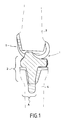
- Fig. 1 is a cut-elevation taken substantially along the sagittal plane of the prosthesis considered in a state of implantation, between the femur and the tibia of a subject in position of extension of the knee.
- Fig. 2 is a section, on a larger scale, in the sagittal plane, showing a constructive feature of an exemplary embodiment of the femoral prosthetic element.
- Fig. 3 is an elevation of the femoral component of a left prosthesis taken along line III-III of FIG. 2.
- Fig. 4 is a section in the sagittal plane, similar to FIG. 2, but concerning the insert of the tibial prosthetic element complementary to the femoral element of FIG. 3 .
- Fig. 5 is a cross section taken along the line VV of FIG. 4.
- Fig. 6 is a section similar to FIG. 2 , showing the base of the tibial prosthetic element.
- Fig. 7 is an elevation along line VII-VII of FIG. 6.
- Fig. 8 is a section similar to FIG. 2, with transverse straight sections showing a constructive characteristic of a trochlean groove.
- Fig. 1 shows the prosthesis according to the invention, consisting of a femoral prosthetic element 1 and a tibial prosthetic element 2 , intended to be adapted, respectively, after bone resection, on the lower femoral epiphysis 3 and on the upper tibial epiphysis 4 .
- the femoral element 1 which may be made of any suitable material known to those skilled in the art, has, according to a sagittal plane and as shown in FIG. 2 , a substantially "U" shape comprising a part or branch 5 , said front or front, a portion or branch 6 , said rear or rear, generally of shorter length than the branch 5 , and a core 7 connecting these branches.
- the internal surface delimited by the femoral element defines, as it were, a polygonal housing 8 intended to fit the epiphysis 3 previously subjected to a complementary resection.
- the femoral element is shaped to present, by the outer surface of its large branch 5 , a patellar surface 13 , as illustrated in FIG. 3 , delimiting, in known manner, a trochlea capable of cooperating with the natural protuberance or with an artificial button presented or carried by the patella, not shown.
- the femoral element 1 forms, by its outer surface corresponding to the core 7 and the branch 6 , two condyles 14 which define a distal portion and a posterior portion.
- the inner 14i and outer 14e condyles have an anatomical shape and are therefore asymmetrical.
- the inner condyle 14i is small and round, while the outer condyle 14e is longer and has a more square shape. Finally, the inner condyles 14i and outer 14e diverge rearwardly.
- the condyles 14 are intended to cooperate, by their distal and posterior parts, with the tibial prosthetic element 2 whose constituent elements are shown in more detail in FIGS. 4 to 6.
- the tibial element 2 comprises a base 16, shown in FIG. 6, whose lower face is provided with at least one shank 17, possibly reinforced by gussets 18 .
- the tail 17 is intended to be implanted in the tibial epiphysis 4 , with or without the presence of a connecting cement.
- the attachment of the base 16 may also involve the presence of screws, not shown.
- the tibial base 16 provides a support plate 19 , preferably plane, for an insert 20 , preferably made of a suitable plastic material, such as polyethylene.
- the insert 20 is shaped to provide, on its top, two glens 21 intended to cooperate with the outer surfaces of the condyles 14 and a spine 23 formed in the sagittal portion from the anterior edge 24 and between the glens 21 .
- the insert 20 is mounted on the base 16 , so as to be rotatable relative thereto.
- the insert 20 has a planar lower face 25 of support on the plate 19.
- the insert has, in addition, from this plane face 25, a finger 26 intended to engage in a bore complementary 27 , arranged in the base 16, so as to define a pivot connection axis ⁇ substantially contained in the sagittal plane S.
- the finger 26 has, from the plane 25 , a base 28 of frustoconical shape, extending by an end 29 of cylindrical shape.
- the bore 27 has a substantially similar shape. This conformation of the bore 27 and the finger 26 allows, very advantageously, a very good transmission of the forces experienced by the insert 20 to the base 16 .
- another conformation with a geometry of revolution, such as cylindrical only, could also be adopted for the finger 26 and the bore 27 .
- the axis ⁇ perpendicular to the plate 19 of the finger 26 and the bore 27, is in the front half A of the femoral prosthetic element 2 .
- the femoral prosthetic element 1 is made to include, in its inter-condylar part, a groove 30 which is shaped so that its outer surface, in consideration of the housing 8 , is set back from that 14.
- This recessed surface is arranged to form, in the connection portion with the branch 5, a lug 31 which defines a kind of cell 32, following which develops a range 33 leading to the rear end portion branch 6 .
- the span 33 has, in cross section along the sagittal plane S , a convex shape, while in cross section, taken perpendicular to the sagittal plane S , the span 33 has a concave shape which appears more particularly in FIG. 3. It should be noted that the convex shape of the span 33 in section along the sagittal plane is made so as to ensure a transition, smooth and without edge, with the condyles 14e and 14i .
- the transverse concavity of the bearing surface 33 is arranged so as to have a radius of curvature R 33 , preferably but not necessarily, of between 15 mm and 30 mm and, more particularly preferably, between 17 mm and 27 mm.
- the span 33 of the femoral element is arranged so as to have a radius of curvature, in the sagittal plane, different in three distinct regions of the scope, namely a region anterior to A 33 , a medial region M 33 and a posterior region P 33 .
- the radius of curvature of the bearing surface 33 in the anterior region is chosen to be between 5 mm and 20 mm and, more preferably, between 8 mm and 14 mm.
- the radius of curvature in the median region of the span 33 is chosen to be preferably between 10 mm and 25 mm and, more preferably, between 12 mm and 20 mm.
- the radius of curvature of the span 33 will be chosen to be preferably between 5 mm and 20 mm and, more preferably, between 10 mm and 18 mm.
- the values of the radii of curvature in the anterior, medial and posterior regions of the span 33 will then be chosen according to the size of the prosthesis and the nature of the desired rollback motion.
- the insert 20 of the tibial element comprises, along the spine 23, a projection 40 , of shape complementary to the cell 32, formed recessed from the front edge 24 and connected to a ramp 41 which develops on the sagittal axis towards the posterior edge 42 of the insert 20 .
- the ramp 41 called sliding, affects, in the sagittal plane, a concave general shape.
- the ramp 41 is shaped so as to present, in cross-section along the sagittal plane and in its front part A 41 , a substantially circular shape, having a radius of curvature R 41 , chosen to be comprised, preferably, between 10 mm and 30 mm and, more preferably, between 13 mm and 25 mm.
- the ramp 41 is extended, in its rear portion P 41 , by a portion that could be considered, seen in the sagittal plane, as being rectilinear.
- the ramp of the tibial insert has, in cross section along the sagittal plane and all points of this section, a radius of curvature greater than the radius of curvature R 41 which could be described as minimum radius of curvature of the insert in the sagittal plane S.
- the ramp 41 has, in cross section in the sagittal plane, as shown in FIG. 5, a convex, smooth and boneless shape, which will be chosen so as to have, preferably but not strictly necessary, a radius of curvature at the vertex R 41bis of between 10 mm and 30 mm and, more particularly preferably, between 14 mm and 24 mm.
- the span 33 and the ramp 41 define between them and from the cell 32, an interval I whose section increases from this cell towards the part or posterior branch 6 .
- the concavity of the span 33 makes it possible to minimize the risk of interference with the patella, natural or prosthetic, of the paired knee.
- This advantageous feature of the invention is completed by the implementation of a trochlear groove 45 for guiding the patella, natural or prosthetic.
- the axis ⁇ 'of the trochlear groove 45 forms an angle ⁇ with respect to the sagittal plane S.
- the trochlear groove is made to have an increasing depth from its end to the cell 32 , as is more particularly the sections BB, CC, DD and EE.
- This depth P measured between the plane P 1 tangential to the vertices of the trochlea adjacent to the groove 45 and the plane P 2 parallel to P 1 passing through the bottom of the groove 45, is then preferably between 0.5 mm and 6 mm.
- the depth P at the beginning of groove 45 (section BB) is between 0.5 mm and 2.5 mm
- the depth P, measured at the end of furrow 45 in the vicinity of cell 32 (section EE ) is between 3.5 mm and 5.7 mm.
- the insert 20 is shaped so as to present, in projection on the plane of the plate 19 , a surface smaller than that of said plate, so that, during a relative rotation of the insert relative to the base , the anterior portion of the insert does not protrude from the plate 19 or the base, thus reducing the risk of interference of the insert with the tissues or ligaments of the paired joint.
- the insert has, in its front part and at the level of the eminence 23 , the front of the stabilizing projection 40 , a bowl 50 for the passage of tissues of the paired knee and, more particularly, the patella and tendon.
Landscapes
- Health & Medical Sciences (AREA)
- Orthopedic Medicine & Surgery (AREA)
- Physical Education & Sports Medicine (AREA)
- Cardiology (AREA)
- Oral & Maxillofacial Surgery (AREA)
- Transplantation (AREA)
- Engineering & Computer Science (AREA)
- Biomedical Technology (AREA)
- Heart & Thoracic Surgery (AREA)
- Vascular Medicine (AREA)
- Life Sciences & Earth Sciences (AREA)
- Animal Behavior & Ethology (AREA)
- General Health & Medical Sciences (AREA)
- Public Health (AREA)
- Veterinary Medicine (AREA)
- Prostheses (AREA)
Applications Claiming Priority (2)
| Application Number | Priority Date | Filing Date | Title |
|---|---|---|---|
| FR0314672A FR2863481B1 (fr) | 2003-12-15 | 2003-12-15 | Prothese de genou antero-postero-stabilisee a plateau tibial pivotant |
| FR0314672 | 2003-12-15 |
Publications (2)
| Publication Number | Publication Date |
|---|---|
| EP1543802A2 true EP1543802A2 (de) | 2005-06-22 |
| EP1543802A3 EP1543802A3 (de) | 2007-09-26 |
Family
ID=34508666
Family Applications (1)
| Application Number | Title | Priority Date | Filing Date |
|---|---|---|---|
| EP04356189A Withdrawn EP1543802A3 (de) | 2003-12-15 | 2004-12-03 | Stabilisierte Knieprothese mit drehbarem Tibialager |
Country Status (2)
| Country | Link |
|---|---|
| EP (1) | EP1543802A3 (de) |
| FR (1) | FR2863481B1 (de) |
Cited By (3)
| Publication number | Priority date | Publication date | Assignee | Title |
|---|---|---|---|---|
| EP1862150A1 (de) * | 2006-05-30 | 2007-12-05 | Dedienne Sante | Vollprothese des Kniegelenks |
| FR2959410A1 (fr) * | 2010-04-30 | 2011-11-04 | Transysteme | Prothese de genou posterostabilisee. |
| US10376370B2 (en) | 2010-09-07 | 2019-08-13 | John Joseph O'Connor | Unicondylar meniscal bearing knee replacement |
Family Cites Families (8)
| Publication number | Priority date | Publication date | Assignee | Title |
|---|---|---|---|---|
| US5011496A (en) | 1988-02-02 | 1991-04-30 | Joint Medical Products Corporation | Prosthetic joint |
| US5370699A (en) * | 1993-01-21 | 1994-12-06 | Orthomet, Inc. | Modular knee joint prosthesis |
| FR2702651B1 (fr) * | 1993-03-16 | 1995-04-28 | Erato | Prothèse du genou. |
| FR2791553B1 (fr) * | 1999-04-01 | 2001-07-06 | Merck Biomaterial France | Prothese de genou antero-postero-stabilisee |
| US6319283B1 (en) * | 1999-07-02 | 2001-11-20 | Bristol-Myers Squibb Company | Tibial knee component with a mobile bearing |
| FR2805456B1 (fr) * | 2000-02-28 | 2002-12-06 | Groupe Lepine | Prothese totale de genou, du type dit "postero-stabilisee" |
| US20030009230A1 (en) * | 2001-06-30 | 2003-01-09 | Gundlapalli Rama Rao V. | Surface sterilizable joint replacement prosthesis component with insert |
| FR2833479B1 (fr) * | 2001-12-13 | 2004-10-01 | Guy Bellier | Prothese de genou |
-
2003
- 2003-12-15 FR FR0314672A patent/FR2863481B1/fr not_active Expired - Fee Related
-
2004
- 2004-12-03 EP EP04356189A patent/EP1543802A3/de not_active Withdrawn
Cited By (4)
| Publication number | Priority date | Publication date | Assignee | Title |
|---|---|---|---|---|
| EP1862150A1 (de) * | 2006-05-30 | 2007-12-05 | Dedienne Sante | Vollprothese des Kniegelenks |
| FR2901689A1 (fr) * | 2006-05-30 | 2007-12-07 | Dedienne Sante Sa | Prothese totale d'articulation du genou |
| FR2959410A1 (fr) * | 2010-04-30 | 2011-11-04 | Transysteme | Prothese de genou posterostabilisee. |
| US10376370B2 (en) | 2010-09-07 | 2019-08-13 | John Joseph O'Connor | Unicondylar meniscal bearing knee replacement |
Also Published As
| Publication number | Publication date |
|---|---|
| FR2863481B1 (fr) | 2006-11-10 |
| FR2863481A1 (fr) | 2005-06-17 |
| EP1543802A3 (de) | 2007-09-26 |
Similar Documents
| Publication | Publication Date | Title |
|---|---|---|
| CA2726034C (fr) | Prothese totale de genou | |
| EP2547291B1 (de) | Knieprothese mit gemischter meniskusscheibe | |
| EP1528902B1 (de) | Knieprothese | |
| EP1765227B1 (de) | Komplette knieprothese | |
| CH630520A5 (fr) | Prothese d'articulation du genou. | |
| EP3449876A1 (de) | Verbesserte knöchelprothese | |
| EP1040796A1 (de) | In der anteroposterioren Richtung stabilisierte Knieprothese | |
| EP0567705B1 (de) | Totale von hinten stabilisierte Knieprothese | |
| FR2926719A1 (fr) | Ensemble compose d'une embase tibiale et d'un insert tibial et prothese comprenant un tel ensemble | |
| EP1862150A1 (de) | Vollprothese des Kniegelenks | |
| EP0709074A1 (de) | Schienbeinprothesenteil für Knieprothese | |
| FR2852819A1 (fr) | Prothese totale postero-stabilisee du genou | |
| FR2976176A1 (fr) | Prothese totale du genou, et gamme d'elements modulaires permettant l'obtention de cette prothese | |
| EP1893135B1 (de) | Unikondyläre anatomische knieprothese | |
| EP3854355B1 (de) | Implantierbare komponente mit verbesserter verankerung für knöchelprothese und eine solche komponente umfassende knöchelprothese | |
| EP1543802A2 (de) | Stabilisierte Knieprothese mit drehbarem Tibialager | |
| FR2630640A1 (fr) | Dispositif de prothese partielle du genou | |
| FR2913591A1 (fr) | Prothese totale du genou, du type dit "postero-stabilisee" | |
| FR2630639A1 (fr) | Dispositif de prothese partielle du genou | |
| FR2758715A1 (fr) | Prothese de condyle femoral | |
| FR2725618A1 (fr) | Prothese femorale d'articulation du genou | |
| FR2959410A1 (fr) | Prothese de genou posterostabilisee. | |
| FR3008606A1 (fr) | Prothese totale de genou | |
| EP2617394B1 (de) | Tibialimplantat für monokondyläre Kniegelenprothese | |
| FR2742651A1 (fr) | Prothese du genou unicompartimentale |
Legal Events
| Date | Code | Title | Description |
|---|---|---|---|
| PUAI | Public reference made under article 153(3) epc to a published international application that has entered the european phase |
Free format text: ORIGINAL CODE: 0009012 |
|
| AK | Designated contracting states |
Kind code of ref document: A2 Designated state(s): AT BE BG CH CY CZ DE DK EE ES FI FR GB GR HU IE IS IT LI LT LU MC NL PL PT RO SE SI SK TR |
|
| AX | Request for extension of the european patent |
Extension state: AL BA HR LV MK YU |
|
| RIN1 | Information on inventor provided before grant (corrected) |
Inventor name: DE WITTE, GERARD Inventor name: VERNIZEAU, MICHEL Inventor name: ARNOULD, HERVE Inventor name: FABRE, THIERRY Inventor name: PUCH, JEAN-MARC Inventor name: OVADIA, HERVE Inventor name: DESCAMP, LOYS Inventor name: MAESTRO, MICHEL Inventor name: RELAVE, MARC Inventor name: PEYROT, JACQUES Inventor name: PASSOT, JEAN-PAUL Inventor name: MILLON, JOSEPH Inventor name: MELERE, GILLES Inventor name: LECUIRE, FRANEOIS Inventor name: HULIN, PAUL-HENRI Inventor name: FAYARD, JEAN-PHILIPPE Inventor name: EYRAUD, GUY Inventor name: DUPRE LA TOUR, LAURENT Inventor name: DEBIESSE, JEAN-LOUIS Inventor name: CHARRET, PHILIPPE Inventor name: BASSO, MAURICE Inventor name: AUGOYARD, MARC |
|
| PUAL | Search report despatched |
Free format text: ORIGINAL CODE: 0009013 |
|
| AK | Designated contracting states |
Kind code of ref document: A3 Designated state(s): AT BE BG CH CY CZ DE DK EE ES FI FR GB GR HU IE IS IT LI LT LU MC NL PL PT RO SE SI SK TR |
|
| AX | Request for extension of the european patent |
Extension state: AL BA HR LV MK YU |
|
| AKX | Designation fees paid | ||
| REG | Reference to a national code |
Ref country code: DE Ref legal event code: 8566 |
|
| STAA | Information on the status of an ep patent application or granted ep patent |
Free format text: STATUS: THE APPLICATION IS DEEMED TO BE WITHDRAWN |
|
| 18D | Application deemed to be withdrawn |
Effective date: 20080327 |