EP3687005B1 - Verriegelungsvorrichtung für ein lan-kabel - Google Patents
Verriegelungsvorrichtung für ein lan-kabel Download PDFInfo
- Publication number
- EP3687005B1 EP3687005B1 EP19179390.0A EP19179390A EP3687005B1 EP 3687005 B1 EP3687005 B1 EP 3687005B1 EP 19179390 A EP19179390 A EP 19179390A EP 3687005 B1 EP3687005 B1 EP 3687005B1
- Authority
- EP
- European Patent Office
- Prior art keywords
- connector
- locking
- lan port
- locking member
- lan
- Prior art date
- Legal status (The legal status is an assumption and is not a legal conclusion. Google has not performed a legal analysis and makes no representation as to the accuracy of the status listed.)
- Active
Links
Images


Classifications
-
- H—ELECTRICITY
- H01—ELECTRIC ELEMENTS
- H01R—ELECTRICALLY-CONDUCTIVE CONNECTIONS; STRUCTURAL ASSOCIATIONS OF A PLURALITY OF MUTUALLY-INSULATED ELECTRICAL CONNECTING ELEMENTS; COUPLING DEVICES; CURRENT COLLECTORS
- H01R13/00—Details of coupling devices of the kinds covered by groups H01R12/70 or H01R24/00 - H01R33/00
- H01R13/62—Means for facilitating engagement or disengagement of coupling parts or for holding them in engagement
- H01R13/627—Snap or like fastening
-
- H—ELECTRICITY
- H01—ELECTRIC ELEMENTS
- H01R—ELECTRICALLY-CONDUCTIVE CONNECTIONS; STRUCTURAL ASSOCIATIONS OF A PLURALITY OF MUTUALLY-INSULATED ELECTRICAL CONNECTING ELEMENTS; COUPLING DEVICES; CURRENT COLLECTORS
- H01R13/00—Details of coupling devices of the kinds covered by groups H01R12/70 or H01R24/00 - H01R33/00
- H01R13/40—Securing contact members in or to a base or case; Insulating of contact members
- H01R13/42—Securing in a demountable manner
-
- H—ELECTRICITY
- H01—ELECTRIC ELEMENTS
- H01R—ELECTRICALLY-CONDUCTIVE CONNECTIONS; STRUCTURAL ASSOCIATIONS OF A PLURALITY OF MUTUALLY-INSULATED ELECTRICAL CONNECTING ELEMENTS; COUPLING DEVICES; CURRENT COLLECTORS
- H01R13/00—Details of coupling devices of the kinds covered by groups H01R12/70 or H01R24/00 - H01R33/00
- H01R13/62—Means for facilitating engagement or disengagement of coupling parts or for holding them in engagement
- H01R13/627—Snap or like fastening
- H01R13/6271—Latching means integral with the housing
- H01R13/6272—Latching means integral with the housing comprising a single latching arm
-
- H—ELECTRICITY
- H01—ELECTRIC ELEMENTS
- H01R—ELECTRICALLY-CONDUCTIVE CONNECTIONS; STRUCTURAL ASSOCIATIONS OF A PLURALITY OF MUTUALLY-INSULATED ELECTRICAL CONNECTING ELEMENTS; COUPLING DEVICES; CURRENT COLLECTORS
- H01R13/00—Details of coupling devices of the kinds covered by groups H01R12/70 or H01R24/00 - H01R33/00
- H01R13/62—Means for facilitating engagement or disengagement of coupling parts or for holding them in engagement
- H01R13/639—Additional means for holding or locking coupling parts together, after engagement, e.g. separate keylock, retainer strap
- H01R13/6397—Additional means for holding or locking coupling parts together, after engagement, e.g. separate keylock, retainer strap with means for preventing unauthorised use
-
- H—ELECTRICITY
- H01—ELECTRIC ELEMENTS
- H01R—ELECTRICALLY-CONDUCTIVE CONNECTIONS; STRUCTURAL ASSOCIATIONS OF A PLURALITY OF MUTUALLY-INSULATED ELECTRICAL CONNECTING ELEMENTS; COUPLING DEVICES; CURRENT COLLECTORS
- H01R24/00—Two-part coupling devices, or either of their cooperating parts, characterised by their overall structure
- H01R24/60—Contacts spaced along planar side wall transverse to longitudinal axis of engagement
- H01R24/62—Sliding engagements with one side only, e.g. modular jack coupling devices
- H01R24/64—Sliding engagements with one side only, e.g. modular jack coupling devices for high frequency, e.g. RJ 45
-
- H—ELECTRICITY
- H01—ELECTRIC ELEMENTS
- H01R—ELECTRICALLY-CONDUCTIVE CONNECTIONS; STRUCTURAL ASSOCIATIONS OF A PLURALITY OF MUTUALLY-INSULATED ELECTRICAL CONNECTING ELEMENTS; COUPLING DEVICES; CURRENT COLLECTORS
- H01R2107/00—Four or more poles
-
- H—ELECTRICITY
- H01—ELECTRIC ELEMENTS
- H01R—ELECTRICALLY-CONDUCTIVE CONNECTIONS; STRUCTURAL ASSOCIATIONS OF A PLURALITY OF MUTUALLY-INSULATED ELECTRICAL CONNECTING ELEMENTS; COUPLING DEVICES; CURRENT COLLECTORS
- H01R2201/00—Connectors or connections adapted for particular applications
- H01R2201/04—Connectors or connections adapted for particular applications for network, e.g. LAN connectors
Definitions
- the present invention relates generally to a locking apparatus for a LAN cable and, more particularly, to a locking apparatus for a LAN cable which can easily and securely lock a LAN port connector connected to the LAN cable when connecting the LAN port connector to a LAN port.
- the present applicant has filed a number of applications for locking apparatuses for USB ports, the locking apparatuses being able to prevent unauthorized memory from being connected to the USB port when a USB memory is connected to the USB port.
- LAN port for connecting to a wired network such as the Internet and a telephone line.
- the LAN port to which a LAN connector connected to a LAN cable is connected can be also connected to an external electronic device or memory. Accordingly, there has been a demand for a device that can securely maintain a locked state even when a LAN port is provided.
- the US 2012/270429 A1 discloses a lock structure of plug of cable including a main body and a key.
- the main body has a locking area, an elastic area with an elastic element, and a lower room for receiving a plug of cable.
- the elastic element tends to stay at a first position.
- the elastic element is at the first position, and a latch of the plug of the cable is unable to be compressed due to the fixation by the elastic element.
- the elastic element is pushed to a second position, and the latch is able to be compressed.
- the KR 101 925 837 B1 discloses a LAN port locking device which cannot separate a LAN connector coupled to a LAN port, according to the preamble of independent claim 1.
- the LAN port locking device comprises: first and second bodies surrounding the LAN connector; a coupling means separably coupling the first and second bodies; at least one elastic latching portion inwardly protruding from the first and second bodies; and a wedge unit having a wedge portion inserted into a lower portion of a push lever of the LAN connector and a latching projection latching a front end of the elastic latching portion.
- the US 2010/136809 A1 discloses a security device for a plug with at least one locking clip, said security device comprising a lockable closure piece which prevent the manual operation of the locking clip.
- the closure piece comprises a closure lower piece which may be fixed to the plug on which a separate closure upper piece is placed.
- the KR 101 621 454 B1 discloses a LAN locking unit and a locking device including the same for inseparably locking a LAN connector connected to a LAN port.
- the LAN locking unit comprises: a connector combining unit which includes a housing having a connector combining hole into which a LAN connector is inserted, at least one elastic locking part protruding to the inside of the housing and the upper cut part through which a push lever of the LAN connector passes; and a wedge unit blocking the descent of the push lever, and having at least one locking sill which is inserted into the lower part of the push lever of the LAN connector and is locked to the elastic locking part of the connector combining unit.
- the US 2017/077641 A1 discloses methods and device for connecting and disconnecting cable connectors to and from communication ports.
- the connector assembly has a ganging member, a plunger member, and a key.
- the ganging member can retain a plurality of cable connectors and be used to simultaneously connect/disconnect groups of cable connectors.
- the plunger member has a plurality of elongated plungers usable to simultaneously unlock or lock the cable connectors.
- the US 2009/007609 A1 discloses a system of a plug locking assembly and a key.
- the plug locking assembly comprises a cover for receiving and holding a plug comprising a latch and a latch support surface positionable under the latch.
- a rotatable cam comprising a stop surface and a slot carrying the latch support surface and interacting with a cam latch comprising an arm.
- the arm is alternately positionable to abut the stop surface and to lie within the slot.
- the key comprises a shaft, a key tab and a limit tab. The key mates with a key receiving member associated with the cover.
- the limit tab is positioned on a top surface of the shaft and helps prevent over-rotation of the latch support member.
- Patent Document 1 Korean Patent No. 10-1391975 .
- the present invention has been made keeping in mind the above problems occurring in the related art, and the present invention is intended to propose a locking apparatus for a LAN cable, which can easily lock or unlock a LAN port connector of the LAN cable connected to a LAN port of an electronic device.
- the problem of the present invention is solved by an assembly of a locking apparatus for a LAN cable and a LAN port connector according to the independent claim 1.
- the dependent claim refers to a further advantageous development of the present invention.
- the locking apparatus for the LAN cable which includes: a connector receiving member receiving a LAN port connector to be coupled thereto, the LAN port connector having a connector body, an elastic hook provided in an upper part of the connector body, and a stopping step provided in a lower part of the connector body; a locking apparatus body coupled to the connector receiving member; and a locking member disturbing operation of the elastic hook of the LAN port connector in the locking apparatus body, and movably installed to reciprocate between a locking position in which disconnecting operation of the connector receiving member and the LAN port connector is unattainable, and a unlocking position in which release operation of the elastic hook is enabled and the disconnecting operation of the connector receiving member is enabled, wherein the locking member is provided with a key way into which an unlocking key is inserted.
- the LAN cable connected to the LAN port is prevented from being disconnected from the LAN port so that security of the LAN port of electronic device may be improved.
- the locking member includes: a locking member body retracting into and coming out of the locking apparatus body, and having a movement-preventive protrusion filling a gap between the LAN port connector and the connector receiving member at the locking position; and a hook blocking part extending from the locking member body, and positioned between the elastic hook and the connector body of the LAN port connector at the locking position to block deformation of the elastic hook.
- operation of the locking member prevents and controls the release operation of the elastic hook of the LAN port connector and the disconnecting operation of the connector receiving member of the LAN port connector at the same time.
- the connector receiving member includes: a receiving part for surrounding and receiving an outside of the connector body of the LAN port connector; and a body coupling part extending from the receiving part and coupled to the locking apparatus body.
- the receiving part includes: opposite side walls facing each other; a pair of upper walls symmetrically connected to each other while facing each other at upper parts of the opposite side walls, and having an open part in which the elastic hook is positioned; and a pair of lower walls symmetrically connected to each other while facing each other, and spaced apart from each other to define a channel through which a cable connected to the LAN port connector passes.
- the locking apparatus of the present invention may be easily coupled to the LAN port connector connected to the LAN port without disconnection of the LAN port connector from the LAN port.
- the receiving part may further include: a stopper protruding from each of the lower walls toward an associated upper wall and stopped by the stopping step of the LAN port connector.
- the receiving part may not be arbitrarily disconnected from the LAN port connector.
- the locking apparatus body includes: an upper wall, a lower wall, opposite side walls, and an elastic locking member protruding to extend from the lower wall to the upper wall, locking the locking member by being inserted into the key way of the locking member, and unlocking the locking member by being removed from the key way by the unlocking key inserted into the key way.
- a first coupling part to which the connector receiving member is coupled and a second coupling part to which the locking member is movably coupled to reciprocate may be provided.
- the LAN port connector can be connected to or disconnected from the LAN port in a state in which the LAN port connector is connected to the LAN port.
- the locked state can be efficiently maintained such that it is impossible to perform disconnecting operation of the LAN port connector without using an authorized unlocking means (the unlocking key).
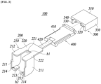
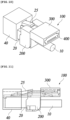
- the locking apparatus for the LAN cable 100 is used to lock the LAN port connector 20 not to be disconnected from the LAN port 40 before using an authorized unlocking means.
- the LAN port connector 20 has a standardized structure to be inserted into and connected to the LAN port 40 standardized generally. That is, as shown in FIGS. 1 and 2 , the LAN port connector 20 includes a connector body 21 to which the LAN cable 10 is inserted in a side and is connected, a connection terminal 23 that is exposed through a surface of the connector body 21, and an elastic hook 25 connected to the connector body 21 to be elastically deformable and recoverable.
- a surface (a lower surface) of the connector body 21 opposite to a surface in which the elastic hook 25 is provided has a stopping step 21a formed into a stepped form.
- the elastic hook 25 is configured such that a first end is connected to the connector body 21, and a free end 25a of a second end is recovered to an original position thereof due to elasticity when a user pushes and releases the elastic hook 25 toward the connector body 21.
- a hook part 26 is formed into the stepped form at opposite edges of the elastic hook 25 and is hooked on a locking step (not shown) provided in an inside surface of the LAN port 40.
- the elastic hook 25 is elastically deformed by contacting with the inside surface of the LAN port 40, and after fully inserted, the elastic hook 25 is elastically recovered again and the hook part 26 is hooked on the locking step inside the LAN port 40 in a so-called one-touch manner, whereby the LAN port connector 20 is connected to the LAN port 40 not to be removed from the LAN port 40.
- the LAN port connector 20 may be removed by being pulled out of and the LAN port 40.
- the hook part 26 of the elastic hook 25 is placed on a position in which the hook part 26 is not hooked on the locking step in the LAN port 40, so that the LAN port connector 20 may be removed from the LAN port 40.
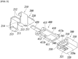
- the locking apparatus for the LAN cable 100 includes a connector receiving member 200, a locking apparatus body 300 coupled to the connector receiving member 200, and a locking member 400 movably installed in the locking apparatus body 300 to reciprocate.
- the connector receiving member 200 includes a receiving part 210 that surrounds the connector body 21 of the LAN port connector 20 and a body coupling part 220 that is connected to the receiving part 210 and coupled to the locking apparatus body 300.
- the receiving part 210 has opposite side walls 211 respectively corresponding to opposite side surfaces of the connector body 21, an upper wall 212 bent and extending from an upper part of each of the opposite side walls 211, and a lower wall 213 bent and extending from a lower part of the opposite side walls 211.
- the upper wall 212 is configured such that a pair of upper walls 212 are symmetrically connected from each of the opposite side walls 211 to each other.
- An open part h1 is provided between the pair of upper walls 212 and in which the elastic hook 25 of the LAN port connector 20 is positioned.
- a pair of lower walls 213 extends symmetrically from each of the opposite side walls 211 to face the upper walls 212, and defines a channel h2 at the center.
- the LAN cable 10 may pass through the channel h2. That is, the channel h2 is provided with a size through which only the LAN cable 10 may pass, and the channel h2 is narrow so that the connector body 21 may not pass through. Accordingly, even when the LAN port connector 20 is connected to the LAN port 40 of the electronic device, the connector body 21 is accommodated in the connector receiving member 200, so the LAN port connector 20 can be easily connected to or disconnected from the LAN port 40.
- the stopper 214 is provided on each lower wall 213 and is stopped by the stopping step 21a provided on a lower surface of the connector body 21.
- the stopper 214 protrudes from a head-end of the lower wall 213 toward the upper wall 212 of the receiving part 210.
- the body coupling part 220 protrudes to extend backward from each of the upper walls 212.
- the body coupling part 220 is formed into a plate shape and has a stopping step 221 exposed toward the open part h1. As shown in FIGS. 8 and 13 , the body coupling part 220 is inserted into and coupled to a first coupling part 340 of the locking apparatus body 300.
- the stopping step 221 is stopped by a stopper 341 provided on a head-end of the first coupling part 340 and prevents the body coupling part 220 coupled to the locking apparatus body 300 from being removed from the first coupling part 340.
- the body coupling part 220 is preferably provided integrally with the receiving part 210.
- the connector receiving member 200 having the above-described configuration is preferably formed of a metal material so as not to be easily deformed by an external force.
- the locking apparatus body 300 includes an upper wall 310, a lower wall 320, and opposite side walls 330.
- the first coupling part 340 and a second coupling part 350 are provided between the upper wall 310 and the lower wall 320.
- the first coupling part 340 is provided with a predetermined depth from a front surface of the locking apparatus body 300, so the body coupling part 220 slides therein and is coupled thereto.
- the above-described stopper 341 protrudes inward.
- the second coupling part 350 penetrates the locking apparatus body 300 from the front to the rear.
- the locking member 400 is movably coupled to reciprocate between a locking position and an unlocking position.
- an elastic locking member 321 is connected to the lower wall 320 to optionally restrict movement of the locking member 400.
- a first end of the elastic locking member 321 is connected to the lower wall 320, and a second end thereof extends to be positioned in the second coupling part 350.
- the locking member 400 includes a locking member body 410 that is coupled to the second coupling part 350 to be slidable and reciprocable, and a hook blocking part 420 protruding forward from the locking member body 410.
- the key way 411 is provided by being recessed into a lower surface of the locking member body 410.
- the key way 411 communicates with a key insertion opening 411a provided on a rear side wall 413 of the locking member body 410.
- a locking member receiving recess 412 is recessed on the lower surface of the locking member body 410 with the same depth as the key way 411, and connected to the key way 411.
- the stopping step 411b is provided between the locking member receiving recess 412 and the key way 411, thus preventing the elastic locking member 321 located inside the key way 411 from being moved freely from the key way 411 to the locking member receiving recess 412.
- the rear side wall 413 is formed in a shape of protruding respectively toward the upper and opposite sides of the locking member body 410, thus being coupled to and shutting an inlet of the second coupling part 350.
- a stopping step 351 is provided in the inside of the inlet of the second coupling part 350 to stop protrusions 413a protruding toward the opposite sides of the rear side wall 413.
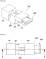
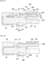
- a movement-preventive protrusion 415 protrudes downward from a front end of the locking member body 410. As shown in FIG. 13 , when the state of moving the locking member 400 to the locking position, as the movement-preventive protrusion 415 is in close contact with an outside of the connector body 21 placed therein, the movement-preventive protrusion 415 performs a function of preventing occurrence of a gap in which the connector body 21 may be moved up and down. Accordingly, since the connector body 21 cannot be moved in the locked state, the connector body 21 and the locking apparatus for the LAN cable 100 of the present invention cannot be disconnected from each other.
- the movement-preventive protrusion 415 is positioned in a protrusion receiving part 323 provided in a front lower part of the locking apparatus body 300.
- the protrusion receiving part 323 corresponds to a space that is opened to the outside by being partially removed from the lower wall 320 of the locking apparatus body 300. Therefore, the locking member 400 moved to the unlocking position has a movement distance to the unlocking position, as the movement-preventive protrusion 415 is inserted into the protrusion receiving part 323 and stopped by a head-end 320a of the lower wall 320.
- the hook blocking part 420 protrudes to extend from the center of a head-end of the locking member body 410 by a predetermined length.
- the hook blocking part 420 has a sufficient length to protrude outward from the front of the connector receiving member 200.
- the LAN port connector 20 of the LAN cable 10 is inserted into the LAN port 40 of the electronic device.
- the locking apparatus for the LAN cable 100 of the present invention may be sequentially coupled to the LAN port connector 20.
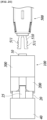
- the connector body 21 is inserted into the inside of the connector receiving member 200 by tilting a position of the connector receiving member 200.
- the stopper 214 passes over the stopping step 21a of the connector body 21, as shown in FIG. 17 .
- the stopper 214 is stopped by the stopping step 21a as shown in FIG. 8 , so that the connector receiving member 200 and the LAN port connector 20 are coupled to each other not to be disconnected from each other.
- coupling the connector receiving member 200 to the LAN port connector 20 proceeds after moving the locking member 400 from the locking apparatus body 300 to the unlocking position.
- the channel h2 is provided in the lower part of the connector receiving member 200 so that the LAN cable 10 can pass through, the LAN port connector 20 and the connector receiving member 200 can be easily coupled to each other without disconnection of the LAN port connector 20 from the LAN port 40.
- the locking member 400 is pushed into the inside of the locking apparatus body 300 as shown in FIGS. 10 to 15 . Then, the elastic locking member 321 is inserted into the key way 411 and is stopped by the stopping step 411b thereby locking the locking member 400 so that the locking member 400 is not removed.
- the hook blocking part 420 is inserted between the upper surface of the connector body 21 and the elastic hook 25. When the hook blocking part 420 is positioned between the upper surface of the connector body 21 and the elastic hook 25, by preventing the elastic hook 25 from being deformed by being pushed toward the connector body 21, the LAN port connector 20 can be removed from the LAN port 40.
- the movement-preventive protrusion 415 is in close contact with the upper surface of the connector body 21, and an upper surface of the locking member 400 remains in a contacted state with the upper wall of the connector receiving member 200.
- the connector body 21 cannot be moved or position thereof cannot be deformed, so a firmly coupled state of the connector body 21 can be maintained.
- the LAN port connector 20 connected to the LAN port 40 is coupled and locked using the locking apparatus for the LAN cable 100 of the present invention, the LAN cable cannot be removed from the electronic device.
- connection of unauthorized connectors to the LAN port 40 can be effectively blocked, and security of the electronic device can be improved.
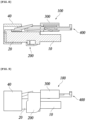
- the locking member 400 should be moved to the unlocking position.
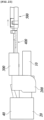
- an unlocking key member 500 inserted into the key way 411 is prepared, and the unlocking key 510 of the unlocking key member 500 is inserted into the key way 411 via the key insertion opening 411a as shown in FIGS. 19 and 21 .
- the unlocking key 510 inserted in the key way 411 interferes with the elastic locking member 321 so that the elastic locking member 321 is released from the stopping step 411b of the key way 411.
- the LAN port connector 20 can be disconnected from the LAN port 40.
- the unlocking key member 500 has the pair of unlocking keys 510 protruding from an unlocking key member body 520 as a head-end.
- the pair of unlocking keys 510 may be opened or closed by manipulating a disconnecting operation knob provided in the unlocking key member body 520.
- the key pattern 511 is formed into a predetermined pattern, and the key pattern 511 has a form corresponding to the pattern groove 411c formed on the inner wall of the key way 411 of the locking member 400.
- the key pattern 511 may be formed into various forms.
- the specific configuration of the above-described unlocking key member 500 is not limited to the description of the present invention, and detailed description thereof will be omitted. That is, the unlocking key member 500 can apply various known unlocking key members.
Landscapes
- Engineering & Computer Science (AREA)
- Computer Security & Cryptography (AREA)
- Details Of Connecting Devices For Male And Female Coupling (AREA)
Claims (2)
- Anordnung einer Verriegelungsvorrichtung für ein LAN-Kabel (100) und einen LAN-Anschlussstecker (20), wobei die Verriegelungsvorrichtung aufweist:ein Steckeraufnahmeelement (200), das den damit zu koppelnden LAN-Anschlussstecker (20) aufnimmt, wobei der LAN-Anschlussstecker (20) einen Steckergehäuse (21), einen in einem oberen Teil des Steckergehäuses (21) vorgesehenen elastischen Haken (25) und eine in einem unteren Teil des Steckergehäuses (21) vorgesehene Stoppstufe (21a) aufweist;einen Verriegelungsvorrichtungskörper (300), der mit dem Steckeraufnahmeelement (200) gekoppelt ist; undein Verriegelungselement (400), das ausgestaltet ist, um eine Betätigung des elastischen Hakens (25) des LAN-Anschlusssteckers (20) in dem Verriegelungsvorrichtungskörper (300) zu verhindern, und das beweglich angebracht ist, um sich zwischen einer Verriegelungsposition, in der eine Trennungsbetätigung des Steckeraufnahmeelements (200) und des LAN-Anschlusssteckers (20) unerreichbar ist, und einer Entriegelungsposition hin- und herzubewegen, in der eine Freigabebetätigung des elastischen Hakens (25) ermöglicht ist und die Trennungsbetätigung des LAN-Anschlusssteckers (200) ermöglicht ist;wobei das Verriegelungselement (400) mit einem Schlüsselweg (411) versehen ist, der für ein Einführen eines Entriegelungsschlüssels (510) ausgestaltet ist, dadurch gekennzeichnet, dass das Verriegelungselement (400) aufweist:einen Verriegelungselementkörper (410), der sich in den Verriegelungsvorrichtungskörper (300) zurückzieht und aus diesem herauskommt und der einen bewegungsverhindemden Vorsprung (415) aufweist, der einen Spalt zwischen dem LAN-Anschlussstecker (20) und dem Steckeraufnahmeelement (200) in der Verriegelungsposition füllt; ein Hakensperrteil (420), das sich von dem Verriegelungselementkörper (410) erstreckt und das zwischen dem elastischen Haken (25) und dem Steckergehäuse (21) des LAN-Anschlusssteckers (20) in der Verriegelungsposition angeordnet ist, um eine Verformung des elastischen Hakens (25) zu blockieren; undwobei die Anordnung dadurch gekennzeichnet ist, dass das Steckeraufnahmeelement (200) aufweist:ein Aufnahmeteil (210) zum Umgeben und Aufnehmen einer Außenseite des Steckergehäuses (21) des LAN-Anschlusssteckers (20); undein Körperkopplungsteil, das sich von dem Aufnahmeteil (210) erstreckt und mit dem Verriegelungsvorrichtungskörper (300) gekoppelt ist;wobei das Aufnahmeteil (210) aufweist:gegenüberliegende Seitenwände (211), die einander zugewandt sind;ein Paar an oberen Wänden (212), die symmetrisch miteinander verbunden sind, während sie an oberen Teilen der gegenüberliegenden Seitenwände (330211) einander zugewandt sind, und die einen offenen Teil (1h) aufweisen, in dem der elastische Haken (25) angeordnet ist; undein Paar an unteren Wänden (213), die symmetrisch miteinander verbunden sind, während sie einander zugewandt sind, und die voneinander beabstandet sind, um einen Kanal (h2) zu bestimmen, durch den ein mit dem LAN-Anschlussstecker (20) verbundenes Kabel verläuft,wobei, wenn das Verriegelungselement (400) in die Verriegelungsposition bewegt wird, der bewegungsverhindemde Vorsprung (415) in engem Kontakt mit der oberen Oberfläche des Steckergehäuses (21) ist, und eine obere Oberfläche des Verriegelungselements (400) in einem kontaktierten Zustand mit der oberen Wand des Steckeraufnahmeelementes (200) bleibt,wobei der Verriegelungsvorrichtungskörper (300) eine obere Wand (310), eine untere Wand (320), gegenüberliegende Seitenwände (330) und ein elastisches Verriegelungselement (321) aufweist, das vorsteht, um sich von der unteren Wand (320) zu der oberen Wand (310) zu erstrecken, und das Verriegelungselement (400) verriegelt, indem es in den Schlüsselweg (411) des Verriegelungselements eingeführt und durch eine an dem Schlüsselweg (411) vorgesehene Verriegelungsanschlagstufe (411b) angehalten wird, und das Verriegelungselement (400) entriegelt, indem es durch den in den Schlüsselweg (411) eingeführten Entriegelungsschlüssel (510) aus dem Schlüsselweg (411) entfernt wird,wobei zwischen der oberen Wand (310) und der unteren Wand (320) ein erstes Kupplungsteil (340), mit dem das Steckeraufnahmeelement (200) gekoppelt ist, und ein zweites Kupplungsteil (350), mit dem das Verriegelungselement (400) beweglich gekoppelt ist, um sich hin und her zu bewegen, vorgesehen sind.
- Anordnung nach Anspruch 1, wobei das Aufnahmeteil (210) des Steckeraufnahmeelementes (200) ferner aufweist:
einen Stopper (221), der von jeder der unteren Wände (213) in Richtung auf eine zugehörige obere Wand vorsteht und durch die Stoppstufe (221) des LAN-Anschlusssteckers (20) angehalten wird.
Applications Claiming Priority (1)
| Application Number | Priority Date | Filing Date | Title |
|---|---|---|---|
| KR1020190010441A KR102067747B1 (ko) | 2019-01-28 | 2019-01-28 | 랜 케이블 락장치 |
Publications (3)
| Publication Number | Publication Date |
|---|---|
| EP3687005A1 EP3687005A1 (de) | 2020-07-29 |
| EP3687005B1 true EP3687005B1 (de) | 2024-10-30 |
| EP3687005C0 EP3687005C0 (de) | 2024-10-30 |
Family
ID=69369892
Family Applications (1)
| Application Number | Title | Priority Date | Filing Date |
|---|---|---|---|
| EP19179390.0A Active EP3687005B1 (de) | 2019-01-28 | 2019-06-11 | Verriegelungsvorrichtung für ein lan-kabel |
Country Status (3)
| Country | Link |
|---|---|
| US (1) | US10637189B1 (de) |
| EP (1) | EP3687005B1 (de) |
| KR (1) | KR102067747B1 (de) |
Families Citing this family (6)
| Publication number | Priority date | Publication date | Assignee | Title |
|---|---|---|---|---|
| KR102351174B1 (ko) * | 2020-05-11 | 2022-01-14 | (주)아이테오솔루션즈 | 랜 포트의 혼동을 방지하는 어댑터 및 이를 포함하는 랜 포트 보안 장치 |
| TWI749863B (zh) * | 2020-11-11 | 2021-12-11 | 四零四科技股份有限公司 | 用於連接埠之保護蓋以及相關的連接埠裝置 |
| CN113518268B (zh) * | 2021-04-20 | 2024-02-27 | 深圳市四海众联网络科技有限公司 | 一种局域网接口装置 |
| KR102711386B1 (ko) * | 2022-06-03 | 2024-09-27 | (주)컴엑스아이 | 접속케이블 라킹장치 |
| EP4287417B1 (de) | 2022-06-03 | 2025-12-03 | Comxi Co., Ltd. | Verbindungskabelverriegelungsvorrichtung |
| EP4340138A1 (de) * | 2022-09-19 | 2024-03-20 | Aptiv Technologies Limited | Gesicherte hochleistungsverbinderanordnung und montageverfahren |
Family Cites Families (30)
| Publication number | Priority date | Publication date | Assignee | Title |
|---|---|---|---|---|
| US5340324A (en) * | 1993-03-23 | 1994-08-23 | Fields James H | Phone jack lock |
| US5429522A (en) * | 1994-01-21 | 1995-07-04 | Burndy Corporation | Protected communications socket |
| US6918782B2 (en) * | 2003-10-08 | 2005-07-19 | The Siemon Company | Modular plug with locking member |
| EP2284963A1 (de) * | 2004-10-22 | 2011-02-16 | Panduit Corp. | Gegentakt-Stecker und Werkzeuge |
| JP4782199B2 (ja) | 2005-08-08 | 2011-09-28 | ライヒル ウント デ−マッサリ アーゲー | プラグ用の安全装置(パッチガード) |
| JP4439449B2 (ja) * | 2005-08-25 | 2010-03-24 | タキゲン製造株式会社 | プラグ抜き取り防止ユニット及び送受信用コード |
| US7354291B2 (en) * | 2006-03-01 | 2008-04-08 | Panduit Corp. | Plug locking assembly |
| US7806706B2 (en) * | 2007-07-03 | 2010-10-05 | Panduit Corp. | Plug locking assembly and system |
| US7695303B2 (en) * | 2007-11-02 | 2010-04-13 | The Siemon Company | Apparatus for plug-in and plug-out protection |
| CH700064A1 (de) * | 2008-12-01 | 2010-06-15 | Reichle & De Massari Fa | Duplex-adapter und sicherungsvorrichtung für eine optische steckverbindung. |
| GB2468188B (en) * | 2009-02-26 | 2011-05-11 | Advanced Fiber Products Ltd | Fibre optic connector assembly |
| US9331426B2 (en) * | 2009-02-26 | 2016-05-03 | Optical Fiber Packaging Corporation | Socket panel for receiving connector plugs with latch guards comprising a security cover plate |
| US7892012B1 (en) * | 2009-08-24 | 2011-02-22 | Archtech Electronics Corporation | Connector locking device |
| US8025514B1 (en) * | 2010-04-23 | 2011-09-27 | Leviton Manufacturing Co., Inc. | Shroud to prevent manipulation of a release mechanism of a plug |
| US8038456B1 (en) * | 2010-04-23 | 2011-10-18 | Leviton Manufacturing Co., Inc | Tamper prevention system having a shroud to partially cover a release mechanism |
| US8632352B2 (en) * | 2010-10-07 | 2014-01-21 | Sentinel Connector Systems, Inc. | Method and apparatus for locking a network cable in a jack |
| TWM413736U (en) | 2011-04-21 | 2011-10-11 | Farng Yiing Entpr Co Ltd | Safety lock assembly of communication wiring |
| JP5760841B2 (ja) * | 2011-08-18 | 2015-08-12 | 富士通株式会社 | ロック解除アダプタ及び通信ケーブルユニット |
| US8348686B1 (en) * | 2011-10-11 | 2013-01-08 | Li-Ping Huang | Plug security structure for electrical connector |
| US8529284B1 (en) * | 2012-04-25 | 2013-09-10 | Quality Computer Accessories Inc. | Connector locking assembly |
| KR101391975B1 (ko) | 2013-02-01 | 2014-05-27 | 안창훈 | Usb 포트 잠금장치 |
| WO2015134683A1 (en) | 2014-03-04 | 2015-09-11 | Netig, Llc | Tool fixing ganged rj45 connectors together and helping for connecting and disconnecting them |
| TWM500381U (zh) * | 2014-07-09 | 2015-05-01 | Yu-He Liang | 網路接頭結構 |
| KR101475861B1 (ko) * | 2014-07-09 | 2014-12-23 | 안창훈 | 랜 포트락장치 |
| KR101621454B1 (ko) * | 2015-07-08 | 2016-05-16 | (주)아이테오솔루션즈 | 랜잠금유닛과 이를 포함하는 잠금장치 |
| TWM524868U (zh) * | 2016-01-08 | 2016-07-01 | You Hung Internat Co Ltd | 網路資訊安全鎖(一) |
| US10120138B2 (en) * | 2016-06-13 | 2018-11-06 | Corning Research & Development Corporation | Connector with trigger locking feature, and cable assemblies and methods including the same |
| US9735507B1 (en) * | 2016-11-23 | 2017-08-15 | Yu-Ho Liang | Locking structure of telecommunication connector |
| TWM549979U (zh) * | 2017-07-07 | 2017-10-01 | Jin-Xing Wen | 網路線插頭防脫落結構 |
| KR101925837B1 (ko) | 2017-10-19 | 2018-12-06 | (주)아이테오솔루션즈 | 설치가 편리한 랜포트 잠금장치 |
-
2019
- 2019-01-28 KR KR1020190010441A patent/KR102067747B1/ko active Active
- 2019-05-16 US US16/414,214 patent/US10637189B1/en active Active
- 2019-06-11 EP EP19179390.0A patent/EP3687005B1/de active Active
Also Published As
| Publication number | Publication date |
|---|---|
| EP3687005C0 (de) | 2024-10-30 |
| KR102067747B1 (ko) | 2020-01-17 |
| EP3687005A1 (de) | 2020-07-29 |
| US10637189B1 (en) | 2020-04-28 |
Similar Documents
| Publication | Publication Date | Title |
|---|---|---|
| EP3687005B1 (de) | Verriegelungsvorrichtung für ein lan-kabel | |
| US9391403B2 (en) | USB port locking device | |
| US8025514B1 (en) | Shroud to prevent manipulation of a release mechanism of a plug | |
| CA2797239C (en) | Cable tamper prevention | |
| KR101961922B1 (ko) | 네트웍 포트 커버모듈 및 이를 포함하는 네트웍 포트 락 장치 | |
| CN105900107B (zh) | 局域网络接口锁定装置 | |
| US9639718B2 (en) | USB link lock device | |
| EP3506146B1 (de) | Vorrichtung zum verriegeln eines usb-anschlusses | |
| EP2747214B1 (de) | Lösemechanismus zur Demontage eines Datensteckers und einer Datensteckdose | |
| KR101925837B1 (ko) | 설치가 편리한 랜포트 잠금장치 | |
| KR102016580B1 (ko) | Qsfp 포트 락장치 | |
| KR102008867B1 (ko) | Usb 케이블 잠금장치 | |
| KR102627959B1 (ko) | 전자기기의 포트 차단모듈 및 이를 포함하는 포트 차단장치 | |
| KR102322076B1 (ko) | Bnc 단자 락 장치 | |
| US12300924B2 (en) | Port blocking module for electronic device and port locking apparatus comprising same | |
| US20180301846A1 (en) | Plug connector | |
| KR102292313B1 (ko) | 랜 포트 잠금 장치 | |
| US7503500B2 (en) | Card connector with anti-mismating device | |
| EP4287417B1 (de) | Verbindungskabelverriegelungsvorrichtung | |
| JP7057409B1 (ja) | 中継コネクタ | |
| KR20260025599A (ko) | Usb 포트 잠금장치 | |
| KR20170102455A (ko) | 유에스비 포트 잠금장치의 키유닛 | |
| GB2234401A (en) | Electrical connectors |
Legal Events
| Date | Code | Title | Description |
|---|---|---|---|
| PUAI | Public reference made under article 153(3) epc to a published international application that has entered the european phase |
Free format text: ORIGINAL CODE: 0009012 |
|
| STAA | Information on the status of an ep patent application or granted ep patent |
Free format text: STATUS: REQUEST FOR EXAMINATION WAS MADE |
|
| 17P | Request for examination filed |
Effective date: 20190611 |
|
| AK | Designated contracting states |
Kind code of ref document: A1 Designated state(s): AL AT BE BG CH CY CZ DE DK EE ES FI FR GB GR HR HU IE IS IT LI LT LU LV MC MK MT NL NO PL PT RO RS SE SI SK SM TR |
|
| AX | Request for extension of the european patent |
Extension state: BA ME |
|
| STAA | Information on the status of an ep patent application or granted ep patent |
Free format text: STATUS: EXAMINATION IS IN PROGRESS |
|
| 17Q | First examination report despatched |
Effective date: 20211213 |
|
| REG | Reference to a national code |
Ref country code: DE Ref legal event code: R079 Free format text: PREVIOUS MAIN CLASS: H01R0013639000 Ipc: H01R0013627000 Ref country code: DE Ref legal event code: R079 Ref document number: 602019061029 Country of ref document: DE Free format text: PREVIOUS MAIN CLASS: H01R0013639000 Ipc: H01R0013627000 |
|
| GRAP | Despatch of communication of intention to grant a patent |
Free format text: ORIGINAL CODE: EPIDOSNIGR1 |
|
| STAA | Information on the status of an ep patent application or granted ep patent |
Free format text: STATUS: GRANT OF PATENT IS INTENDED |
|
| RIC1 | Information provided on ipc code assigned before grant |
Ipc: H01R 24/64 20110101ALI20240604BHEP Ipc: H01R 13/639 20060101ALI20240604BHEP Ipc: H01R 107/00 20060101ALI20240604BHEP Ipc: H01R 13/627 20060101AFI20240604BHEP |
|
| INTG | Intention to grant announced |
Effective date: 20240703 |
|
| GRAS | Grant fee paid |
Free format text: ORIGINAL CODE: EPIDOSNIGR3 |
|
| GRAA | (expected) grant |
Free format text: ORIGINAL CODE: 0009210 |
|
| STAA | Information on the status of an ep patent application or granted ep patent |
Free format text: STATUS: THE PATENT HAS BEEN GRANTED |
|
| AK | Designated contracting states |
Kind code of ref document: B1 Designated state(s): AL AT BE BG CH CY CZ DE DK EE ES FI FR GB GR HR HU IE IS IT LI LT LU LV MC MK MT NL NO PL PT RO RS SE SI SK SM TR |
|
| REG | Reference to a national code |
Ref country code: GB Ref legal event code: FG4D |
|
| REG | Reference to a national code |
Ref country code: CH Ref legal event code: EP |
|
| REG | Reference to a national code |
Ref country code: DE Ref legal event code: R096 Ref document number: 602019061029 Country of ref document: DE |
|
| REG | Reference to a national code |
Ref country code: IE Ref legal event code: FG4D |
|
| U01 | Request for unitary effect filed |
Effective date: 20241128 |
|
| U07 | Unitary effect registered |
Designated state(s): AT BE BG DE DK EE FI FR IT LT LU LV MT NL PT RO SE SI Effective date: 20241209 |
|
| PG25 | Lapsed in a contracting state [announced via postgrant information from national office to epo] |
Ref country code: HR Free format text: LAPSE BECAUSE OF FAILURE TO SUBMIT A TRANSLATION OF THE DESCRIPTION OR TO PAY THE FEE WITHIN THE PRESCRIBED TIME-LIMIT Effective date: 20241030 Ref country code: IS Free format text: LAPSE BECAUSE OF FAILURE TO SUBMIT A TRANSLATION OF THE DESCRIPTION OR TO PAY THE FEE WITHIN THE PRESCRIBED TIME-LIMIT Effective date: 20250228 |
|
| PG25 | Lapsed in a contracting state [announced via postgrant information from national office to epo] |
Ref country code: ES Free format text: LAPSE BECAUSE OF FAILURE TO SUBMIT A TRANSLATION OF THE DESCRIPTION OR TO PAY THE FEE WITHIN THE PRESCRIBED TIME-LIMIT Effective date: 20241030 |
|
| PG25 | Lapsed in a contracting state [announced via postgrant information from national office to epo] |
Ref country code: NO Free format text: LAPSE BECAUSE OF FAILURE TO SUBMIT A TRANSLATION OF THE DESCRIPTION OR TO PAY THE FEE WITHIN THE PRESCRIBED TIME-LIMIT Effective date: 20250130 |
|
| PG25 | Lapsed in a contracting state [announced via postgrant information from national office to epo] |
Ref country code: GR Free format text: LAPSE BECAUSE OF FAILURE TO SUBMIT A TRANSLATION OF THE DESCRIPTION OR TO PAY THE FEE WITHIN THE PRESCRIBED TIME-LIMIT Effective date: 20250131 |
|
| PG25 | Lapsed in a contracting state [announced via postgrant information from national office to epo] |
Ref country code: PL Free format text: LAPSE BECAUSE OF FAILURE TO SUBMIT A TRANSLATION OF THE DESCRIPTION OR TO PAY THE FEE WITHIN THE PRESCRIBED TIME-LIMIT Effective date: 20241030 |
|
| PG25 | Lapsed in a contracting state [announced via postgrant information from national office to epo] |
Ref country code: RS Free format text: LAPSE BECAUSE OF FAILURE TO SUBMIT A TRANSLATION OF THE DESCRIPTION OR TO PAY THE FEE WITHIN THE PRESCRIBED TIME-LIMIT Effective date: 20250130 |
|
| PG25 | Lapsed in a contracting state [announced via postgrant information from national office to epo] |
Ref country code: SM Free format text: LAPSE BECAUSE OF FAILURE TO SUBMIT A TRANSLATION OF THE DESCRIPTION OR TO PAY THE FEE WITHIN THE PRESCRIBED TIME-LIMIT Effective date: 20241030 |
|
| PGFP | Annual fee paid to national office [announced via postgrant information from national office to epo] |
Ref country code: GB Payment date: 20250625 Year of fee payment: 7 |
|
| PG25 | Lapsed in a contracting state [announced via postgrant information from national office to epo] |
Ref country code: SK Free format text: LAPSE BECAUSE OF FAILURE TO SUBMIT A TRANSLATION OF THE DESCRIPTION OR TO PAY THE FEE WITHIN THE PRESCRIBED TIME-LIMIT Effective date: 20241030 |
|
| PG25 | Lapsed in a contracting state [announced via postgrant information from national office to epo] |
Ref country code: CZ Free format text: LAPSE BECAUSE OF FAILURE TO SUBMIT A TRANSLATION OF THE DESCRIPTION OR TO PAY THE FEE WITHIN THE PRESCRIBED TIME-LIMIT Effective date: 20241030 |
|
| U20 | Renewal fee for the european patent with unitary effect paid |
Year of fee payment: 7 Effective date: 20250627 |
|
| PLBE | No opposition filed within time limit |
Free format text: ORIGINAL CODE: 0009261 |
|
| STAA | Information on the status of an ep patent application or granted ep patent |
Free format text: STATUS: NO OPPOSITION FILED WITHIN TIME LIMIT |
|
| 26N | No opposition filed |
Effective date: 20250731 |
|
| REG | Reference to a national code |
Ref country code: CH Ref legal event code: H13 Free format text: ST27 STATUS EVENT CODE: U-0-0-H10-H13 (AS PROVIDED BY THE NATIONAL OFFICE) Effective date: 20260127 |
|
| PG25 | Lapsed in a contracting state [announced via postgrant information from national office to epo] |
Ref country code: MC Free format text: LAPSE BECAUSE OF FAILURE TO SUBMIT A TRANSLATION OF THE DESCRIPTION OR TO PAY THE FEE WITHIN THE PRESCRIBED TIME-LIMIT Effective date: 20241030 |