EP3686361A1 - Wc körbchen und verfahren zu dessen herstellung - Google Patents
Wc körbchen und verfahren zu dessen herstellung Download PDFInfo
- Publication number
- EP3686361A1 EP3686361A1 EP19218397.8A EP19218397A EP3686361A1 EP 3686361 A1 EP3686361 A1 EP 3686361A1 EP 19218397 A EP19218397 A EP 19218397A EP 3686361 A1 EP3686361 A1 EP 3686361A1
- Authority
- EP
- European Patent Office
- Prior art keywords
- hanger
- housing
- toilet
- spiral spring
- basket
- Prior art date
- Legal status (The legal status is an assumption and is not a legal conclusion. Google has not performed a legal analysis and makes no representation as to the accuracy of the status listed.)
- Granted
Links
Images

Classifications
-
- E—FIXED CONSTRUCTIONS
- E03—WATER SUPPLY; SEWERAGE
- E03D—WATER-CLOSETS OR URINALS WITH FLUSHING DEVICES; FLUSHING VALVES THEREFOR
- E03D9/00—Sanitary or other accessories for lavatories ; Devices for cleaning or disinfecting the toilet room or the toilet bowl; Devices for eliminating smells
- E03D9/02—Devices adding a disinfecting, deodorising, or cleaning agent to the water while flushing
- E03D9/03—Devices adding a disinfecting, deodorising, or cleaning agent to the water while flushing consisting of a separate container with an outlet through which the agent is introduced into the flushing water, e.g. by suction ; Devices for agents in direct contact with flushing water
- E03D9/032—Devices connected to or dispensing into the bowl
-
- E—FIXED CONSTRUCTIONS
- E03—WATER SUPPLY; SEWERAGE
- E03D—WATER-CLOSETS OR URINALS WITH FLUSHING DEVICES; FLUSHING VALVES THEREFOR
- E03D9/00—Sanitary or other accessories for lavatories ; Devices for cleaning or disinfecting the toilet room or the toilet bowl; Devices for eliminating smells
- E03D9/02—Devices adding a disinfecting, deodorising, or cleaning agent to the water while flushing
- E03D2009/024—Devices adding a disinfecting, deodorising, or cleaning agent to the water while flushing using a solid substance
-
- E—FIXED CONSTRUCTIONS
- E03—WATER SUPPLY; SEWERAGE
- E03D—WATER-CLOSETS OR URINALS WITH FLUSHING DEVICES; FLUSHING VALVES THEREFOR
- E03D9/00—Sanitary or other accessories for lavatories ; Devices for cleaning or disinfecting the toilet room or the toilet bowl; Devices for eliminating smells
- E03D9/02—Devices adding a disinfecting, deodorising, or cleaning agent to the water while flushing
- E03D2009/026—Devices adding a disinfecting, deodorising, or cleaning agent to the water while flushing using a gel-form substance
Definitions
- the present invention relates to a toilet basket with a housing for receiving a hygiene product and a hanger for fastening the toilet basket to an edge of a toilet bowl.
- the invention further relates to a method for producing such a toilet basket.
- Generic toilet baskets are known and are used to hold a hygiene product, for example a solid, powder or gel product, which is used for disinfection, cleaning and / or scenting.
- a hygiene product for example a solid, powder or gel product, which is used for disinfection, cleaning and / or scenting.
- the filled toilet basket is hung using the hanger over the edge of a toilet bowl in such a way that the housing lies on the inside of the toilet bowl immediately below the rim of the sink.
- water runs along the edge of the flush into the toilet bowl and also flushes through the housing of the toilet basket with suitable openings.
- a certain amount of the hygiene product stored in the housing is dissolved in each rinsing process and mixed with the rinsing water.
- Known toilet baskets generally have a one-piece hanger with a straight shaft, on the end facing away from the housing a hook is formed, which can be placed over the edge of the toilet bowl for attachment.
- the disadvantage here is that the length of the shaft is unchangeable and therefore no adaptation to different toilet geometries, in particular to different edge heights, can be carried out. If the rim is very low, the housing hangs far below the rim of the sink, which means that the toilet basket does not hang stable overall. Conversely, if the edge is particularly high, the housing may not be able to be arranged below the rinsing edge, but rather hangs in the area of the edge where it is not adequately washed by water. In addition, the toilet basket also does not hang stable in this case and could, for example, come loose when the toilet seat is opened and fall into the toilet.
- hangers for toilet baskets have already been proposed, which are formed in two parts.
- the two parts of such a hanger can be connected to one another via a locking mechanism, which offers different setting options and thus enables a certain length adjustment to different toilet edges.
- Such two-part hangers are significantly more complex to manufacture and therefore more expensive.
- a user has to adapt the two-part hanger to the dimensions of his toilet. For this the user may have to reach into the toilet bowl several times and position the hanger until the correct length setting is found. This is perceived as unsanitary and therefore disadvantageous.
- the toilet basket according to the invention comprises a housing for receiving a hygiene product and a hanger of length L adjoining the housing for attachment to an edge of a toilet bowl, the hanger having an end facing the housing and an end facing away from the housing and wherein the hanger is wound from its end facing away from the housing to a coil spring.
- the spiral spring is preferably in the form of a spiral, particularly preferably an Archimedean spiral, or for example a logarithmic spiral or a hyperbolic spiral, or variations thereof.
- the winding of the hanger into a spiral spring allows the toilet basket to be easily adapted to different toilet geometries, in particular to different edge heights, for example by placing the hanger with the wound spiral spring over the toilet rim and then the housing against the restoring force of the spiral spring inside the toilet bowl is pulled down until it comes to rest below the flush rim or the housing in the toilet is placed below the flush rim and the wound hanger is pulled over the toilet rim.
- the coil spring is at least partially unrolled and finally tightens the housing securely in the position below the flushing rim due to the restoring spring force.
- the remaining, unrolled part of the spiral spring acts as a hook with which the hanger is fixed to the upper edge of the toilet bowl.
- the spiral spring can be unrolled to any length between a minimum and a maximum value.
- the resilient spring force of the coil spring always acts, by means of which the housing is clamped below the flushing rim. To this way, an optimal fit and hold of the toilet basket below the flush rim can be achieved for numerous toilet geometries and rim heights.
- the adaptation to the edge of the toilet can be done in a single step, which means that a user only has to reach into the area of the toilet bowl once to place the housing or to position it by unrolling and thus pretensioning the spiral spring directly below the flushing rim.
- the hanger in the area of the spiral spring in an outer area of the upper edge of the toilet bowl with one hand and pulls the housing down with the other hand on the inside of the toilet bowl until it comes to rest below the flushing rim and there locked, or he places and holds the housing below the flushing rim in the desired position with one hand and with the other hand pulls the hanger on the spiral spring beyond the toilet rim around the top of the toilet bowl, so that the remaining hanger in one latched outside of the upper edge of the toilet bowl.
- the spiral spring unrolls by a certain length, depending on the height of the toilet rim. The remaining, unrolled part of the spiral spring presses against the edge of the toilet bowl from the outside. Repeated reaching into the toilet bowl for optimal adjustment is not necessary.
- the winding axis of the coil spring i.e. the axis around which the spiral spring is wound is essentially perpendicular to the longitudinal extent of the hanger.
- the hanger is wound at least over half its length L as a spiral spring when not in use.
- the hanger is wound in the unused state at least over three-quarters of its length L as a spiral spring.
- the invention provides that the hanger is designed as a spiral spring over a large part of its length.
- a straight shaft section can adjoin the length section of the hanger wound as a spiral spring in the region of the end of the hanger facing the housing.
- the hanger is made in one piece. This is advantageous in terms of production technology and thus lowers the production costs.
- the housing and the hanger can also be formed in one piece, ie the hanger is produced together with the housing and molded onto it in a common manufacturing step.
- the housing and the hanger can be manufactured as two separate parts, ie the hanger is manufactured separately from the housing and then connected to the housing.
- the invention also relates to a method for producing a toilet basket according to the invention.
- the hanger can be produced by lamination of a stretched and an unstretched film. To do this, the two different foils are first brought together. The desired shape of the hanger is then punched out of this film composite. Subsequent activation by means of heat pulls the stretched film together, which forms the spiral spring in combination with the unstretched film. The hanger manufactured in this way is finally connected to a housing.
- the hanger can also be manufactured using an injection molding process.
- the coil spring can be injection molded directly using a suitable mold. It is also conceivable that a plastic band forming the spring is first produced by the injection molding process in the unrolled state - that is to say largely flat. Through a special process control it can be achieved that the strip then rolls up to a spiral spring after removal from the mold. For this purpose, for example, different cooling conditions produced by suitable temperature control can be used to influence the shrinkage in such a way that a kind of bimetal effect is achieved in the plastic.
- an initially flat plastic strip can be formed into a spiral spring by kinking and rolling up, as is known from rolled-up sheet metal measuring tapes.
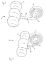
- a toilet basket according to the invention designated as a whole by 1, is shown. It comprises a housing 2, which is used to hold a hygiene product. This can be, for example, a solid or powdery or gel-like product.
- the housing 2 can be opened to fill the housing 2 with the hygiene product. Through openings or breakthroughs in the wall of the housing 2, not shown in the figures, water can enter the housing 2 and hygiene product dissolved in the water can exit the housing 2 again.
- a hanger 3 is molded onto the housing 2 and is used to fasten the toilet basket 1 to an edge of a toilet bowl.
- the hanger 3 has an end 3a facing the housing 2 and an end 3b facing away from the housing 2. Starting from its end 3b facing away from the housing 2, the hanger 3 is wound into a spiral spring 4. In the completely unrolled state, the hanger 3 has a length L between the end 3a and the end 3b.
- the length L can be approximately 20 cm, for example.
- the hanger 3 is more than three quarters of its length L in Figure 1 wound as a spiral spring. Only in the area adjacent to the end 3a remains a straight shaft section 3c, along which the hanger 3 is not rolled up.
- FIG Figure 2 shows a further exemplary embodiment of the toilet basket 1 according to the invention. It essentially corresponds to that in FIG Figure 1 illustrated embodiment, with the only difference that the straight shaft portion 3c is shorter. The consequence of this is that the part of the hanger 3 wound up to form a spiral spring 4 almost reaches the housing 2. The hanger 3 is thus wound over almost its entire length L to the coil spring 4.
- a longer straight shaft section 3c, as in FIG Figure 1 shown, can have advantages in terms of packaging, among other things, since in a blister pack several toilet baskets 1 can be nested in one another such that the housing 2 of one toilet basket 1 comes to rest in the region of the straight shaft section 3c of the second toilet basket 1. A tight packing is possible in this way.
- the length of the straight shaft section 3c can be based on the dimensions of the housing 2.
- the hanger 3 is wound up to the spiral spring 4 that the spiral spring 4 in the in Figures 1 and 2 shown rest position, ie in the unused state, has about 3 complete turns.
- the hanger 3 and the housing 2 formed in one piece and manufactured in an injection molding process from a suitable plastic.
- the injection mold already has a spiral shape.
- FIGs 3 and 4 show an inventive toilet basket 1 attached to the edge 5 of a toilet bowl 6.
- the Figure 4 shows a section of a toilet bowl 6 with an edge 5 of a height H2.
- the height H1 is greater than the height H2.
- the part of the hanger 3 wound up to the spiral spring 4 is shown in the illustrations of FIG Figures 3 and 4 held in an outside region 7 of the rim 5, while the housing 2 on the inside of the toilet bowl 6 is pulled down against the restoring force of the spiral spring 4 along the rim 5 until it comes to rest below a flush rim 8 of the toilet bowl 6.
- the part of the hanger 3 wound up to the spiral spring 4 unrolls, whereby the higher the edge 5 of the toilet bowl 6 is, the more it unrolls.
- a comparison of the Figures 3 and 4 shows that a longer section of the spiral spring 4 of the hanger 3 is unrolled at an edge 5 with a high height H1 than with an edge 5 with a lower height H2.
- a longer section of the hanger 3 remains wound up to the spiral spring 4 at an edge 5 with a lower height H2 than with an edge 5 with a larger height H1.
- the winding of the hanger 3 into a spiral spring 4 thus allows flexible and continuous adaptation to different edge heights of toilet bowls 6.
- the restoring force of the spiral spring 4 in the position of the toilet basket 1 ensures a firm and stable fit of the toilet basket 1.
Landscapes
- Health & Medical Sciences (AREA)
- Public Health (AREA)
- Epidemiology (AREA)
- Life Sciences & Earth Sciences (AREA)
- Engineering & Computer Science (AREA)
- Hydrology & Water Resources (AREA)
- Water Supply & Treatment (AREA)
- Non-Flushing Toilets (AREA)
Abstract
Description
- Die vorliegende Erfindung betrifft ein WC-Körbchen mit einem Gehäuse für die Aufnahme eines Hygieneprodukts sowie einem Hänger für die Befestigung des WC-Körbchens an einem Rand einer Toilettenschüssel. Die Erfindung betrifft weiterhin ein Verfahren zur Herstellung eines solchen WC-Körbchens.
- Gattungsgemäße WC-Körbchen sind bekannt und dienen der Aufnahme eines Hygieneprodukts, beispielsweise eines festen, pulverförmigen oder gelförmigen Produkts, welches der Desinfektion, Reinigung und/oder Beduftung dient. Das befüllte WC-Körbchen wird dabei mithilfe des Hängers derart über den Rand einer Toilettenschüssel gehängt, dass das Gehäuse auf der Innenseite der Toilettenschüssel unmittelbar unterhalb des Spülrandes zu liegen kommt. Bei Betätigung der Toilettenspülung läuft Wasser entlang des Spülrandes in die Toilettenschüssel und durchspült dabei auch das mit geeigneten Öffnungen versehene Gehäuse des WC-Körbchens. Hierdurch wird bei jedem Spülvorgang eine gewisse Menge des in dem Gehäuse bevorrateten Hygieneprodukts gelöst und dem Spülwasser beigemischt.
- Bekannte WC-Körbchen weisen dabei in der Regel einen einteiligen Hänger mit einem geraden Schaft auf, an dessen dem Gehäuse abgewandten Ende ein Haken angeformt ist, welcher sich zur Befestigung über den Rand der Toilettenschüssel legen lässt. Nachteilig ist dabei, dass die Länge des Schafts unveränderlich ist und daher keine Anpassung an unterschiedliche Toilettengeometrien, insbesondere an unterschiedliche Randhöhen, vorgenommen werden kann. Bei einem sehr niedrigen Rand hängt das Gehäuse weit unterhalb des Spülrandes, wodurch das WC-Körbchen insgesamt nicht stabil hängt. Ist der Rand umgekehrt besonders hoch, so lässt sich das Gehäuse unter Umständen nicht unterhalb des Spülrandes anordnen sondern hängt im Bereich des Randes, wo es nicht ausreichend von Wasser umspült wird. Zudem hängt das WC-Körbchen auch in diesem Falle nicht stabil und könnte sich beispielsweise beim Öffnen der Toilettenbrille lösen und in das WC fallen.
- Um diesen Nachteilen zu begegnen wurden bereits Hänger für WC-Körbchen vorgeschlagen, die zweiteilig ausgebildet sind. Die beiden Teile eines solchen Hängers können über einen Rastmechanismus miteinander verbunden sein, der verschiedene Einstellmöglichkeiten bietet und so eine gewisse Längenanpassung an unterschiedliche Toilettenränder ermöglicht. Derartige zweiteilige Hänger sind jedoch deutlich aufwendiger in der Herstellung und daher kostenintensiver. Zudem muss ein Nutzer den zweiteiligen Hänger an die Maße seiner Toilette anpassen. Hierzu muss der Nutzer unter Umständen mehrmals in die Toilettenschüssel hineingreifen und den Hänger positionieren, bis die richtige Längeneinstellung gefunden ist. Dies wird als unhygienisch und daher als nachteilig empfunden.
- Die Aufgabe der vorliegenden Erfindung liegt daher in der Bereitstellung eines WC-Körbchens, welches eine Anpassung an unterschiedliche Toilettengeometrien erlaubt und gleichzeitig günstig in der Herstellung und einfach im Gebrauch ist. Eine weitere Aufgabe der Erfindung liegt in der Bereitstellung eines Verfahrens zur Herstellung eines solchen WC-Körbchens.
- Diese Aufgaben werden gelöst durch ein WC-Körbchen mit den Merkmalen des Patentanspruchs 1 sowie durch ein Verfahren zur Herstellung eines solchen WC-Körbchens gemäß Patentanspruch 6.
- Spezielle Ausgestaltungen und Weiterbildungen der Erfindung sind Gegenstand der abhängigen Patentansprüche.
- Gemäß Patentanspruch 1 umfasst das erfindungsgemäße WC-Körbchen ein Gehäuse für die Aufnahme eines Hygieneprodukts sowie einen an das Gehäuse angrenzenden Hänger einer Länge L zur Befestigung an einem Rand einer Toilettenschüssel, wobei der Hänger ein dem Gehäuse zugewandtes Ende und ein dem Gehäuse abgewandtes Ende aufweist und wobei der Hänger ausgehend von seinem dem Gehäuse abgewandten Ende zu einer Spiralfeder aufgewickelt ist.
- Vorzugsweise hat die Spiralfeder die Form einer Spirale, besonders bevorzugt einer archimedischen Spirale, oder beispielsweise einer logarithmischen Spirale oder einer hyperbolischen Spirale, oder von Variationen davon.
- Die Aufwicklung des Hängers zu einer Spiralfeder erlaubt eine einfache Anpassung des WC-Körbchens an unterschiedliche Toilettengeometrien, insbesondere an unterschiedliche Randhöhen, wobei hierzu beispielsweise der Hänger mit der aufgewickelten Spiralfeder über den Toilettenrand gelegt wird und anschließend das Gehäuse gegen die Rückstellkraft der Spiralfeder innerhalb der Toilettenschüssel so weit nach unten gezogen wird, bis es unterhalb des Spülrandes zu liegen kommt, oder das Gehäuse in der Toilette, unterhalb des Spülrandes platziert wird und der aufgewickelte Hänger über den Toilettenrand gezogen wird. Die Spiralfeder wird dabei zumindest teilweise entrollt und spannt das Gehäuse schließlich aufgrund der rückstellenden Federkraft sicher in der Position unterhalb des Spülrandes fest. Der verbleibende, nicht entrollte Teil der Spiralfeder wirkt als Haken, mit dem der Hänger am oberen Rand der Toilettenschüssel fixiert wird. Von besonderem Vorteil ist dabei die Möglichkeit der kontinuierlichen Längenanpassung, da die Spiralfeder zwischen einem Minimal- und einem Maximalwert auf eine beliebige Länge entrollt werden kann. Unabhängig von der Längeneinstellung wirkt dabei stets die rückstellende Federkraft der Spiralfeder, durch die das Gehäuse unterhalb des Spülrandes festgespannt wird. Auf diese Weise kann für zahlreiche Toilettengeometrien und Randhöhen ein optimaler Sitz und Halt des WC-Körbchens unterhalb des Spülrandes erreicht werden.
- Zudem kann die Anpassung an den Toilettenrand in einem einzigen Schritt erfolgen, das heißt, ein Nutzer muss lediglich einmal in den Bereich der Toilettenschüssel hineingreifen, um das Gehäuse zu platzieren, bzw. durch Entrollen und damit Vorspannen der Spiralfeder unmittelbar unterhalb des Spülrandes zu positionieren. Er hält hierzu beispielsweise mit einer Hand den Hänger im Bereich der Spiralfeder in einem außenseitigen Bereich des oberen Randes der Toilettenschüssel fest und zieht das Gehäuse mit der anderen Hand auf der Innenseite der Toilettenschüssel nach unten, bis es unterhalb des Spülrandes zu liegen kommt und sich dort verrastet, oder er platziert und hält mit einer Hand das Gehäuse unterhalb des Spülrandes auf der gewünschten Position fest und zieht mit der anderen Hand den Hänger an der Spiralfeder über den Toilettenrand hinaus um den oberen Rand der Toilettenschüssel hinaus, so dass der verbleibende Hänger in einem außenseitigen Bereich des oberen Randes der Toilettenschüssel verrastet. Die Spiralfeder entrollt sich dabei um eine gewisse, von der Höhe des Toilettenrandes abhängige Länge. Der verbleibende, nicht entrollte Teil der Spiralfeder drückt von außen gegen den Rand der Toilettenschüssel. Ein mehrfaches Hineingreifen in die Toilettenschüssel zwecks optimaler Justierung entfällt.
- Die Wickelachse der Spiralfeder, d.h. diejenige Achse, um welche die Spiralfeder aufgewickelt ist, liegt im Wesentlichen senkrecht zur Längserstreckung des Hängers.
- Gemäß einem Vorschlag der Erfindung ist der Hänger im nicht eingesetzten Zustand mindestens über die Hälfte seiner Länge L als Spiralfeder aufgewickelt. Gemäß einer weiteren Ausbildung ist der Hänger im nicht eingesetzten Zustand mindestens über Dreiviertel seiner Länge L als Spiralfeder auf gewickelt. Mit anderen Worten sieht die Erfindung vor, dass der Hänger über einen Großteil seiner Länge als Spiralfeder ausgebildet ist. An den als Spiralfeder aufgewickelten Längenabschnitt des Hängers kann sich im Bereich des dem Gehäuse zugewandten Endes des Hängers ein gerader Schaftabschnitt anschließen.
- Gemäß einer Ausgestaltung der Erfindung ist der Hänger einteilig ausgebildet. Dies ist fertigungstechnisch von Vorteil und senkt somit die Herstellungskosten.
- Es können auch das Gehäuse und der Hänger einteilig ausgebildet sein, d.h. der Hänger wird zusammen mit dem Gehäuse und an dieses fest angeformt in einem gemeinsamen Fertigungsschritt hergestellt. Alternativ können Gehäuse und Hänger als zwei einzelne Teile hergestellt werden, d.h. der Hänger wird separat von dem Gehäuse gefertigt und anschließend mit dem Gehäuse verbunden.
- Die Erfindung betrifft auch ein Verfahren zur Herstellung eines erfindungsgemäßen WC-Körbchens.
- Gemäß Anspruch 6 kann der Hänger durch Lamination einer gereckten und einer ungereckten Folie hergestellt werden. Dazu werden zunächst die beiden unterschiedlichen Folien aufeinander gebracht. Die gewünschte Form des Hängers wird sodann aus diesem Folienverbund ausgestanzt. Durch anschließende Aktivierung mittels Wärme zieht sich die gereckte Folie zusammen, wodurch sich im Verbund mit der ungereckten Folie die Spiralfeder ausbildet. Der solchermaßen gefertigte Hänger wird schließlich mit einem Gehäuse verbunden.
- Unabhängig von diesem Verfahren kann der Hänger auch in einem Spritzgussverfahren hergestellt werden. Dabei kann die Spiralfeder unter Verwendung einer geeigneten Form unmittelbar spritzgegossen werden. Es ist auch denkbar, dass ein die Feder bildendes Kunststoffband zunächst im Spritzgussverfahren im nicht aufgerollten Zustand - also größtenteils flach - hergestellt wird. Durch eine spezielle Prozessführung kann dabei erreicht werden, dass sich das Band nach der Entformung anschließend zu einer Spiralfeder aufrollt. Hierzu können beispielsweise durch geeignete Temperaturführung hergeführte, unterschiedliche Abkühlverhältnisse ausgenutzt werden, um die Schwindung so zu beeinflussen, dass eine Art Bimetalleffekt im Kunststoff erzielt wird.
- Alternativ kann auch ein zunächst flach ausgebildetes Kunststoffband durch Knickung und Aufrollen zu einer Spiralfeder umgeformt werden, so wie es von aufgerollten Blechmaßbändern bekannt ist.
- Im Folgenden wird die Erfindung anhand von Ausführungsbeispielen und unter Bezugnahme auf die beigefügten Zeichnungen näher erläutert. Es zeigen:
- Figur 1:
- schematische Darstellung einer ersten Ausführungsform eines erfindungsgemäßen WC-Körbchens in perspektivischer Ansicht;
- Figur 2:
- schematische Darstellung einer zweiten Ausführungsform eines erfindungsgemäßen WC-Körbchens in perspektivischer Ansicht;
- Figur 3:
- ein erfindungsgemäßes WC-Körbchen in Einsatzlage am Rand einer Toilettenschüssel in schematischer Schnittdarstellung;
- Figur 4:
- das WC-Körbchen aus
Figur 3 in Einsatzlage an einem weniger hohen Rand einer anderen Toilettenschüssel in schematischer Schnittdarstellung. - In
Figur 1 ist ein im Ganzen mit 1 bezeichnetes erfindungsgemäßes WC-Körbchen dargestellt. Es umfasst ein Gehäuse 2, welches der Aufnahme eines Hygieneprodukts dient. Hierbei kann es sich beispielsweise um ein festes oder pulverförmiges oder gelförmiges Produkt handeln. Zur Befüllung des Gehäuses 2 mit dem Hygieneprodukt kann das Gehäuse 2 geöffnet werden. Über in den Figuren nicht dargestellte Öffnungen bzw. Durchbrüche in der Wand des Gehäuses 2 kann Wasser in das Gehäuse 2 eintreten und in dem Wasser gelöstes Hygieneprodukt kann wieder aus dem Gehäuse 2 austreten. - An dem Gehäuse 2 ist ein Hänger 3 angeformt, der der Befestigung des WC-Körbchens 1 an einem Rand einer Toilettenschüssel dient. Der Hänger 3 weist ein dem Gehäuse 2 zugewandtes Ende 3a und ein dem Gehäuse 2 abgewandtes Ende 3b auf. Ausgehend von seinem dem Gehäuse 2 abgewandten Ende 3b ist der Hänger 3 zu einer Spiralfeder 4 aufgewickelt. Im vollkommen entrollten Zustand weist der Hänger 3 zwischen dem Ende 3a und dem Ende 3b eine Länge L auf. Die Länge L kann beispielsweise etwa 20 cm betragen. Über mehr als Dreiviertel seiner Länge L ist der Hänger 3 in der
Figur 1 als Spiralfeder aufgewickelt. Lediglich in dem an das Ende 3a angrenzenden Bereich verbleibt ein gerader Schaftabschnitt 3c, längs dessen der Hänger 3 nicht aufgerollt ist. -
Figur 2 zeigt ein weiteres Ausführungsbeispiel des erfindungsgemäßen WC-Körbchens 1. Es entspricht im Wesentlichen dem inFigur 1 dargestellten Ausführungsbeispiel, mit dem einzigen Unterschied, dass der gerade Schaftabschnitt 3c kürzer ausgebildet ist. Dies hat zur Folge, dass der zu einer Spiralfeder 4 aufgewickelte Teil des Hängers 3 nahezu bis an das Gehäuse 2 heranreicht. Der Hänger 3 ist damit nahezu über seine gesamte Länge L zur Spiralfeder 4 aufgewickelt. Ein länger ausgebildeter gerader Schaftabschnitt 3c, wie inFigur 1 gezeigt, kann unter anderem verpackungstechnische Vorteile haben, da in einer Blisterpackung mehrere WC-Körbchen 1 derart ineinander geschachtelt werden können, dass das Gehäuse 2 des einen WC-Körbchens 1 im Bereich des geraden Schaftabschnitts 3c des zweiten WC-Körbchens 1 zu liegen kommt. Auf diese Weise ist eine dichte Packung möglich. Die Länge des geraden Schaftabschnitts 3c kann sich dabei an den Abmessungen des Gehäuses 2 orientieren. - Der Hänger 3 ist derart zur Spiralfeder 4 aufgewickelt, dass die Spiralfeder 4 in der in den
Figuren 1 und 2 gezeigten Ruhelage, d.h. im nicht eingesetzten Zustand, etwa 3 vollständige Windungen aufweist. - Bei dem WC-Körbchen 1 gemäß den
Figuren 1 und 2 sind der Hänger 3 und das Gehäuse 2 einteilig ausgebildet und in einem Spritzgussverfahren aus einem geeigneten Kunststoff hergestellt. Dazu weist die Spritzgussform bereits eine Spiralform auf. - Die
Figuren 3 und 4 zeigen ein erfindungsgemäßes WC-Körbchen 1 in Einsatzlage befestigt am Rand 5 einer Toilettenschüssel 6. Dabei ist inFigur 3 ein Ausschnitt einer Toilettenschüssel 6 mit einem Rand 5 einer Höhe H1 dargestellt, während dieFigur 4 einen Ausschnitt aus einer Toilettenschüssel 6 mit einem Rand 5 einer Höhe H2 zeigt. Die Höhe H1 ist größer als die Höhe H2. - Zur Befestigung des WC-Körbchens 1 an dem Rand 5 der Toilettenschüssel 6 wird der zur Spiralfeder 4 aufgewickelte Teil des Hängers 3 gemäß den Darstellungen der
Figuren 3 und 4 in einem außenseitigen Bereich 7 des Randes 5 festgehalten, während das Gehäuse 2 auf der Innenseite der Toilettenschüssel 6 gegen die rückstellende Kraft der Spiralfeder 4 entlang des Randes 5 nach unten gezogen wird, bis es unterhalb eines Spülrandes 8 der Toilettenschüssel 6 zur Anlage kommt. Der zu der Spiralfeder 4 aufgewickelte Teil des Hängers 3 entrollt sich dabei, wobei er sich umso mehr entrollt, je höher der Rand 5 der Toilettenschüssel 6 ist. - Ein Vergleich der
Figuren 3 und 4 zeigt, dass bei einem Rand 5 mit großer Höhe H1 ein längerer Abschnitt der Spiralfeder 4 des Hängers 3 entrollt wird als bei einem Rand 5 mit geringerer Höhe H2. Entsprechend verbleibt bei einem Rand 5 mit geringerer Höhe H2 ein längerer Abschnitt des Hängers 3 zur Spiralfeder 4 aufgewickelt als bei einem Rand 5 mit größerer Höhe H1. Die Aufwicklung des Hängers 3 zu einer Spiralfeder 4 erlaubt somit eine flexible und kontinuierliche Anpassung an unterschiedliche Randhöhen von Toilettenschüsseln 6. Durch die rückstellende Kraft der Spiralfeder 4 in Einsatzlage des WC-Körbchens 1 ist ein fester und stabiler Sitz des WC-Körbchens 1 sichergestellt. -
- 1
- WC-Körbchen
- 2
- Gehäuse
- 3
- Hänger
- 3a
- Ende
- 3b
- Ende
- 3c
- gerader Schaftabschnitt
- 4
- Spiralfeder
- 5
- Rand
- 6
- Toilettenschüssel
- 7
- Bereich
- 8
- Spülrand
Claims (6)
- WC-Körbchen (1), umfassend ein Gehäuse (2) für die Aufnahme eines Hygieneprodukts sowie einen an das Gehäuse (2) angrenzenden Hänger (3) einer Länge L zur Befestigung an einem Rand (5) einer Toilettenschüssel (6), wobei der Hänger (3) ein dem Gehäuse (2) zugewandtes Ende (3a) und ein dem Gehäuse (2) abgewandtes Ende (3b) aufweist, dadurch gekennzeichnet, dass der Hänger (3) ausgehend von seinem dem Gehäuse (2) abgewandten Ende (3b) zu einer Spiralfeder (4) aufgewickelt ist.
- WC-Körbchen (1) nach Anspruch 1, dadurch gekennzeichnet, dass der Hänger (3) im nicht eingesetzten Zustand mindestens über die Hälfte seiner Länge L als Spiralfeder (4) aufgewickelt ist.
- WC-Körbchen (1) nach Anspruch 1 oder 2, dadurch gekennzeichnet, dass der Hänger (3) im nicht eingesetzten Zustand mindestens über Dreiviertel seiner Länge L als Spiralfeder (4) aufgewickelt ist.
- WC-Körbchen (1) nach einem der Ansprüche 1 bis 3, dadurch gekennzeichnet, dass der Hänger (3) einteilig ausgebildet ist.
- WC-Körbchen (1) nach einem der Ansprüche 1 bis 4, dadurch gekennzeichnet, dass das Gehäuse (2) und der Hänger (3) einteilig ausgebildet sind.
- Verfahren zur Herstellung eines WC-Körbchens (1) nach einem der Ansprüche 1 bis 5,
dadurch gekennzeichnet, dass der Hänger (3) durch Lamination einer gereckten und einer ungereckten Folie hergestellt wird, wobei das Verfahren die folgenden Schritte umfasst:- Aufeinanderbringen einer gereckten und einer ungereckten Folie;- Ausstanzen der gewünschten Form des Hängers (3) aus dem Folienverbund;- Aktivierung mittels Wärme, vorzugsweise durch bei der Lamination eingebrachte Wärme, wodurch sich die gereckte Folie zusammenzieht und im Verbund mit der ungereckten Folie die Spiralfeder (4) ausbildet;- Verbinden des Hängers (3) mit einem Gehäuse (2).
Applications Claiming Priority (1)
| Application Number | Priority Date | Filing Date | Title |
|---|---|---|---|
| DE102019200739.2A DE102019200739A1 (de) | 2019-01-22 | 2019-01-22 | WC Körbchen und Verfahren zu dessen Herstellung |
Publications (2)
| Publication Number | Publication Date |
|---|---|
| EP3686361A1 true EP3686361A1 (de) | 2020-07-29 |
| EP3686361B1 EP3686361B1 (de) | 2022-07-06 |
Family
ID=69411048
Family Applications (1)
| Application Number | Title | Priority Date | Filing Date |
|---|---|---|---|
| EP19218397.8A Active EP3686361B1 (de) | 2019-01-22 | 2019-12-20 | Verfahren zur herstellung eines wc-körbchens |
Country Status (2)
| Country | Link |
|---|---|
| EP (1) | EP3686361B1 (de) |
| DE (1) | DE102019200739A1 (de) |
Citations (3)
| Publication number | Priority date | Publication date | Assignee | Title |
|---|---|---|---|---|
| GB1235144A (en) * | 1968-07-18 | 1971-06-09 | Secto Co Ltd | Solid lavatory disinfectants and the like |
| GB2339212A (en) * | 1998-07-06 | 2000-01-19 | Reckitt & Colman France | Container for toilet bowl with improved hook |
| GB2426981A (en) * | 2005-06-09 | 2006-12-13 | Brian Parry Slade | Dispensing device |
Family Cites Families (1)
| Publication number | Priority date | Publication date | Assignee | Title |
|---|---|---|---|---|
| US10344462B2 (en) * | 2014-09-08 | 2019-07-09 | S. C. Johnson & Son, Inc. | Toilet rimblock and method of making such rimblock |
-
2019
- 2019-01-22 DE DE102019200739.2A patent/DE102019200739A1/de not_active Withdrawn
- 2019-12-20 EP EP19218397.8A patent/EP3686361B1/de active Active
Patent Citations (3)
| Publication number | Priority date | Publication date | Assignee | Title |
|---|---|---|---|---|
| GB1235144A (en) * | 1968-07-18 | 1971-06-09 | Secto Co Ltd | Solid lavatory disinfectants and the like |
| GB2339212A (en) * | 1998-07-06 | 2000-01-19 | Reckitt & Colman France | Container for toilet bowl with improved hook |
| GB2426981A (en) * | 2005-06-09 | 2006-12-13 | Brian Parry Slade | Dispensing device |
Also Published As
| Publication number | Publication date |
|---|---|
| EP3686361B1 (de) | 2022-07-06 |
| DE102019200739A1 (de) | 2020-07-23 |
Similar Documents
| Publication | Publication Date | Title |
|---|---|---|
| EP1379198B1 (de) | Entfernbare, im wesentlichen zylindrische implantate | |
| EP2145585B1 (de) | Punktionsverschluss zum Verschließen eines eine Punktionsöffnung aufweisenden Hohlorgans, insbesondere eines Blutgefäßes | |
| DE102010036695B4 (de) | Isolierbehälter | |
| DE8605949U1 (de) | Gerät zum Putzen bzw. Zubereiten von für den Verzehr bestimmten Früchten mit einem innenliegenden Kern und einer Außenschale | |
| DE3542944A1 (de) | Vorrichtung zum zusatz von desinfektionsmitteln oder dergleichen in das spuelwasser eines wc | |
| EP3686361B1 (de) | Verfahren zur herstellung eines wc-körbchens | |
| EP1709935A1 (de) | Kofferdamm und/oder Lippen- und Wangenexpander | |
| EP1795664B1 (de) | In einer Umhüllungsfolie aufgenommener Schaumstoffstreifen | |
| WO2014125051A1 (de) | VERFAHREN ZUM HERSTELLEN EINER KARTUSCHE ZUM AUFNEHMEN UND DOSIERBAREN ABGEBEN EINES FLIEßFÄHIGEN DENTALMATERIALS UND EINE SOLCHE KARTUSCHE | |
| EP1449969A2 (de) | Haltevorrichtung für einen Spender eines WC-Deodorants | |
| DE102014008139A1 (de) | Rahmenteil für einen Gurtaufroller sowie Verfahren zur Herstellung | |
| DE10144523A1 (de) | Rollo bzw. Abdeckung zum Auf- und Abwickeln einer Tuch-, Folien- oder Netzbahn mit Befestigungsvorrichtung und Griff | |
| DE102022002341A1 (de) | Trägersystem zum Lagern von Naturdarm mit Ausrutschhindernis | |
| DE102013004077A1 (de) | Verfahren zum Herstellen einer Kartusche zum Aufnehmen und dosierbaren Abgeben eines fließfähigen Dentalmaterials und eine solche Kartusche | |
| DE202005016524U1 (de) | Anputzleiste und aufgerollte Anputzleiste | |
| DE3025707C2 (de) | Armierter Schlauch, insbes. Sanitärschlauch | |
| DE10220548B4 (de) | Befestigung eines biegsamen Aufzugs auf einem Zylinder einer Rotationsdruckmaschine | |
| WO2021094063A1 (de) | Wc-körbchen | |
| DE102024110137A1 (de) | WC-Körbchen | |
| EP2317862B1 (de) | Hülle, gestell zu ihrer aufnahme und verfahren zur herstellung von dönerartigen formkörpern | |
| DE3310033A1 (de) | Sanitaerschlauch | |
| DE1909545B2 (de) | Zahnprothesendose | |
| DE9014745U1 (de) | Dosierspeicher für Waschmaschinen o.dgl. | |
| EP4472424A2 (de) | Träger zum lagern von naturdarm mit rückhaltemitteln | |
| DE202016006726U1 (de) | Form zur Herstellung von Nahrungsmittelprodukten, die mit einem Trägerelement ausgestattet ist |
Legal Events
| Date | Code | Title | Description |
|---|---|---|---|
| PUAI | Public reference made under article 153(3) epc to a published international application that has entered the european phase |
Free format text: ORIGINAL CODE: 0009012 |
|
| STAA | Information on the status of an ep patent application or granted ep patent |
Free format text: STATUS: REQUEST FOR EXAMINATION WAS MADE |
|
| 17P | Request for examination filed |
Effective date: 20191220 |
|
| AK | Designated contracting states |
Kind code of ref document: A1 Designated state(s): AL AT BE BG CH CY CZ DE DK EE ES FI FR GB GR HR HU IE IS IT LI LT LU LV MC MK MT NL NO PL PT RO RS SE SI SK SM TR |
|
| AX | Request for extension of the european patent |
Extension state: BA ME |
|
| GRAP | Despatch of communication of intention to grant a patent |
Free format text: ORIGINAL CODE: EPIDOSNIGR1 |
|
| STAA | Information on the status of an ep patent application or granted ep patent |
Free format text: STATUS: GRANT OF PATENT IS INTENDED |
|
| RIC1 | Information provided on ipc code assigned before grant |
Ipc: E03D 9/03 20060101AFI20220128BHEP |
|
| INTG | Intention to grant announced |
Effective date: 20220216 |
|
| GRAS | Grant fee paid |
Free format text: ORIGINAL CODE: EPIDOSNIGR3 |
|
| GRAA | (expected) grant |
Free format text: ORIGINAL CODE: 0009210 |
|
| STAA | Information on the status of an ep patent application or granted ep patent |
Free format text: STATUS: THE PATENT HAS BEEN GRANTED |
|
| AK | Designated contracting states |
Kind code of ref document: B1 Designated state(s): AL AT BE BG CH CY CZ DE DK EE ES FI FR GB GR HR HU IE IS IT LI LT LU LV MC MK MT NL NO PL PT RO RS SE SI SK SM TR |
|
| REG | Reference to a national code |
Ref country code: AT Ref legal event code: REF Ref document number: 1502977 Country of ref document: AT Kind code of ref document: T Effective date: 20220715 Ref country code: CH Ref legal event code: EP |
|
| REG | Reference to a national code |
Ref country code: DE Ref legal event code: R096 Ref document number: 502019004869 Country of ref document: DE |
|
| REG | Reference to a national code |
Ref country code: IE Ref legal event code: FG4D Free format text: LANGUAGE OF EP DOCUMENT: GERMAN |
|
| REG | Reference to a national code |
Ref country code: LT Ref legal event code: MG9D |
|
| REG | Reference to a national code |
Ref country code: NL Ref legal event code: MP Effective date: 20220706 |
|
| PG25 | Lapsed in a contracting state [announced via postgrant information from national office to epo] |
Ref country code: SE Free format text: LAPSE BECAUSE OF FAILURE TO SUBMIT A TRANSLATION OF THE DESCRIPTION OR TO PAY THE FEE WITHIN THE PRESCRIBED TIME-LIMIT Effective date: 20220706 Ref country code: RS Free format text: LAPSE BECAUSE OF FAILURE TO SUBMIT A TRANSLATION OF THE DESCRIPTION OR TO PAY THE FEE WITHIN THE PRESCRIBED TIME-LIMIT Effective date: 20220706 Ref country code: PT Free format text: LAPSE BECAUSE OF FAILURE TO SUBMIT A TRANSLATION OF THE DESCRIPTION OR TO PAY THE FEE WITHIN THE PRESCRIBED TIME-LIMIT Effective date: 20221107 Ref country code: NO Free format text: LAPSE BECAUSE OF FAILURE TO SUBMIT A TRANSLATION OF THE DESCRIPTION OR TO PAY THE FEE WITHIN THE PRESCRIBED TIME-LIMIT Effective date: 20221006 Ref country code: NL Free format text: LAPSE BECAUSE OF FAILURE TO SUBMIT A TRANSLATION OF THE DESCRIPTION OR TO PAY THE FEE WITHIN THE PRESCRIBED TIME-LIMIT Effective date: 20220706 Ref country code: LV Free format text: LAPSE BECAUSE OF FAILURE TO SUBMIT A TRANSLATION OF THE DESCRIPTION OR TO PAY THE FEE WITHIN THE PRESCRIBED TIME-LIMIT Effective date: 20220706 Ref country code: LT Free format text: LAPSE BECAUSE OF FAILURE TO SUBMIT A TRANSLATION OF THE DESCRIPTION OR TO PAY THE FEE WITHIN THE PRESCRIBED TIME-LIMIT Effective date: 20220706 Ref country code: FI Free format text: LAPSE BECAUSE OF FAILURE TO SUBMIT A TRANSLATION OF THE DESCRIPTION OR TO PAY THE FEE WITHIN THE PRESCRIBED TIME-LIMIT Effective date: 20220706 Ref country code: ES Free format text: LAPSE BECAUSE OF FAILURE TO SUBMIT A TRANSLATION OF THE DESCRIPTION OR TO PAY THE FEE WITHIN THE PRESCRIBED TIME-LIMIT Effective date: 20220706 |
|
| PG25 | Lapsed in a contracting state [announced via postgrant information from national office to epo] |
Ref country code: PL Free format text: LAPSE BECAUSE OF FAILURE TO SUBMIT A TRANSLATION OF THE DESCRIPTION OR TO PAY THE FEE WITHIN THE PRESCRIBED TIME-LIMIT Effective date: 20220706 Ref country code: IS Free format text: LAPSE BECAUSE OF FAILURE TO SUBMIT A TRANSLATION OF THE DESCRIPTION OR TO PAY THE FEE WITHIN THE PRESCRIBED TIME-LIMIT Effective date: 20221106 Ref country code: HR Free format text: LAPSE BECAUSE OF FAILURE TO SUBMIT A TRANSLATION OF THE DESCRIPTION OR TO PAY THE FEE WITHIN THE PRESCRIBED TIME-LIMIT Effective date: 20220706 Ref country code: GR Free format text: LAPSE BECAUSE OF FAILURE TO SUBMIT A TRANSLATION OF THE DESCRIPTION OR TO PAY THE FEE WITHIN THE PRESCRIBED TIME-LIMIT Effective date: 20221007 |
|
| REG | Reference to a national code |
Ref country code: DE Ref legal event code: R097 Ref document number: 502019004869 Country of ref document: DE |
|
| PG25 | Lapsed in a contracting state [announced via postgrant information from national office to epo] |
Ref country code: SM Free format text: LAPSE BECAUSE OF FAILURE TO SUBMIT A TRANSLATION OF THE DESCRIPTION OR TO PAY THE FEE WITHIN THE PRESCRIBED TIME-LIMIT Effective date: 20220706 Ref country code: RO Free format text: LAPSE BECAUSE OF FAILURE TO SUBMIT A TRANSLATION OF THE DESCRIPTION OR TO PAY THE FEE WITHIN THE PRESCRIBED TIME-LIMIT Effective date: 20220706 Ref country code: DK Free format text: LAPSE BECAUSE OF FAILURE TO SUBMIT A TRANSLATION OF THE DESCRIPTION OR TO PAY THE FEE WITHIN THE PRESCRIBED TIME-LIMIT Effective date: 20220706 Ref country code: CZ Free format text: LAPSE BECAUSE OF FAILURE TO SUBMIT A TRANSLATION OF THE DESCRIPTION OR TO PAY THE FEE WITHIN THE PRESCRIBED TIME-LIMIT Effective date: 20220706 |
|
| PLBE | No opposition filed within time limit |
Free format text: ORIGINAL CODE: 0009261 |
|
| STAA | Information on the status of an ep patent application or granted ep patent |
Free format text: STATUS: NO OPPOSITION FILED WITHIN TIME LIMIT |
|
| PG25 | Lapsed in a contracting state [announced via postgrant information from national office to epo] |
Ref country code: SK Free format text: LAPSE BECAUSE OF FAILURE TO SUBMIT A TRANSLATION OF THE DESCRIPTION OR TO PAY THE FEE WITHIN THE PRESCRIBED TIME-LIMIT Effective date: 20220706 Ref country code: EE Free format text: LAPSE BECAUSE OF FAILURE TO SUBMIT A TRANSLATION OF THE DESCRIPTION OR TO PAY THE FEE WITHIN THE PRESCRIBED TIME-LIMIT Effective date: 20220706 |
|
| 26N | No opposition filed |
Effective date: 20230411 |
|
| PG25 | Lapsed in a contracting state [announced via postgrant information from national office to epo] |
Ref country code: AL Free format text: LAPSE BECAUSE OF FAILURE TO SUBMIT A TRANSLATION OF THE DESCRIPTION OR TO PAY THE FEE WITHIN THE PRESCRIBED TIME-LIMIT Effective date: 20220706 |
|
| P01 | Opt-out of the competence of the unified patent court (upc) registered |
Effective date: 20230530 |
|
| REG | Reference to a national code |
Ref country code: CH Ref legal event code: PL |
|
| REG | Reference to a national code |
Ref country code: BE Ref legal event code: MM Effective date: 20221231 |
|
| PG25 | Lapsed in a contracting state [announced via postgrant information from national office to epo] |
Ref country code: SI Free format text: LAPSE BECAUSE OF FAILURE TO SUBMIT A TRANSLATION OF THE DESCRIPTION OR TO PAY THE FEE WITHIN THE PRESCRIBED TIME-LIMIT Effective date: 20220706 Ref country code: LU Free format text: LAPSE BECAUSE OF NON-PAYMENT OF DUE FEES Effective date: 20221220 |
|
| PG25 | Lapsed in a contracting state [announced via postgrant information from national office to epo] |
Ref country code: LI Free format text: LAPSE BECAUSE OF NON-PAYMENT OF DUE FEES Effective date: 20221231 Ref country code: IE Free format text: LAPSE BECAUSE OF NON-PAYMENT OF DUE FEES Effective date: 20221220 Ref country code: CH Free format text: LAPSE BECAUSE OF NON-PAYMENT OF DUE FEES Effective date: 20221231 |
|
| PG25 | Lapsed in a contracting state [announced via postgrant information from national office to epo] |
Ref country code: BE Free format text: LAPSE BECAUSE OF NON-PAYMENT OF DUE FEES Effective date: 20221231 |
|
| PG25 | Lapsed in a contracting state [announced via postgrant information from national office to epo] |
Ref country code: IT Free format text: LAPSE BECAUSE OF FAILURE TO SUBMIT A TRANSLATION OF THE DESCRIPTION OR TO PAY THE FEE WITHIN THE PRESCRIBED TIME-LIMIT Effective date: 20220706 |
|
| PG25 | Lapsed in a contracting state [announced via postgrant information from national office to epo] |
Ref country code: HU Free format text: LAPSE BECAUSE OF FAILURE TO SUBMIT A TRANSLATION OF THE DESCRIPTION OR TO PAY THE FEE WITHIN THE PRESCRIBED TIME-LIMIT; INVALID AB INITIO Effective date: 20191220 |
|
| PG25 | Lapsed in a contracting state [announced via postgrant information from national office to epo] |
Ref country code: CY Free format text: LAPSE BECAUSE OF FAILURE TO SUBMIT A TRANSLATION OF THE DESCRIPTION OR TO PAY THE FEE WITHIN THE PRESCRIBED TIME-LIMIT Effective date: 20220706 |
|
| PG25 | Lapsed in a contracting state [announced via postgrant information from national office to epo] |
Ref country code: MK Free format text: LAPSE BECAUSE OF FAILURE TO SUBMIT A TRANSLATION OF THE DESCRIPTION OR TO PAY THE FEE WITHIN THE PRESCRIBED TIME-LIMIT Effective date: 20220706 |
|
| PG25 | Lapsed in a contracting state [announced via postgrant information from national office to epo] |
Ref country code: MC Free format text: LAPSE BECAUSE OF FAILURE TO SUBMIT A TRANSLATION OF THE DESCRIPTION OR TO PAY THE FEE WITHIN THE PRESCRIBED TIME-LIMIT Effective date: 20220706 |
|
| PG25 | Lapsed in a contracting state [announced via postgrant information from national office to epo] |
Ref country code: TR Free format text: LAPSE BECAUSE OF FAILURE TO SUBMIT A TRANSLATION OF THE DESCRIPTION OR TO PAY THE FEE WITHIN THE PRESCRIBED TIME-LIMIT Effective date: 20220706 Ref country code: MC Free format text: LAPSE BECAUSE OF FAILURE TO SUBMIT A TRANSLATION OF THE DESCRIPTION OR TO PAY THE FEE WITHIN THE PRESCRIBED TIME-LIMIT Effective date: 20220706 |
|
| PG25 | Lapsed in a contracting state [announced via postgrant information from national office to epo] |
Ref country code: BG Free format text: LAPSE BECAUSE OF FAILURE TO SUBMIT A TRANSLATION OF THE DESCRIPTION OR TO PAY THE FEE WITHIN THE PRESCRIBED TIME-LIMIT Effective date: 20220706 |
|
| PG25 | Lapsed in a contracting state [announced via postgrant information from national office to epo] |
Ref country code: MT Free format text: LAPSE BECAUSE OF FAILURE TO SUBMIT A TRANSLATION OF THE DESCRIPTION OR TO PAY THE FEE WITHIN THE PRESCRIBED TIME-LIMIT Effective date: 20220706 |
|
| PGFP | Annual fee paid to national office [announced via postgrant information from national office to epo] |
Ref country code: DE Payment date: 20251211 Year of fee payment: 7 |
|
| PGFP | Annual fee paid to national office [announced via postgrant information from national office to epo] |
Ref country code: GB Payment date: 20251219 Year of fee payment: 7 |
|
| PGFP | Annual fee paid to national office [announced via postgrant information from national office to epo] |
Ref country code: FR Payment date: 20251229 Year of fee payment: 7 |
|
| REG | Reference to a national code |
Ref country code: AT Ref legal event code: MM01 Ref document number: 1502977 Country of ref document: AT Kind code of ref document: T Effective date: 20241220 |
|
| PG25 | Lapsed in a contracting state [announced via postgrant information from national office to epo] |
Ref country code: AT Free format text: LAPSE BECAUSE OF NON-PAYMENT OF DUE FEES Effective date: 20241220 |
|
| PGFP | Annual fee paid to national office [announced via postgrant information from national office to epo] |
Ref country code: AT Payment date: 20260410 Year of fee payment: 5 |