EP3685113B1 - Method for cooling water monitoring and control - Google Patents
Method for cooling water monitoring and control Download PDFInfo
- Publication number
- EP3685113B1 EP3685113B1 EP18779935.8A EP18779935A EP3685113B1 EP 3685113 B1 EP3685113 B1 EP 3685113B1 EP 18779935 A EP18779935 A EP 18779935A EP 3685113 B1 EP3685113 B1 EP 3685113B1
- Authority
- EP
- European Patent Office
- Prior art keywords
- cooling water
- heat exchanger
- transfer efficiency
- heat transfer
- heat
- Prior art date
- Legal status (The legal status is an assumption and is not a legal conclusion. Google has not performed a legal analysis and makes no representation as to the accuracy of the status listed.)
- Active
Links
Images


Classifications
-
- F—MECHANICAL ENGINEERING; LIGHTING; HEATING; WEAPONS; BLASTING
- F28—HEAT EXCHANGE IN GENERAL
- F28F—DETAILS OF HEAT-EXCHANGE AND HEAT-TRANSFER APPARATUS, OF GENERAL APPLICATION
- F28F27/00—Control arrangements or safety devices specially adapted for heat-exchange or heat-transfer apparatus
- F28F27/003—Control arrangements or safety devices specially adapted for heat-exchange or heat-transfer apparatus specially adapted for cooling towers
-
- C—CHEMISTRY; METALLURGY
- C02—TREATMENT OF WATER, WASTE WATER, SEWAGE, OR SLUDGE
- C02F—TREATMENT OF WATER, WASTE WATER, SEWAGE, OR SLUDGE
- C02F1/00—Treatment of water, waste water, or sewage
- C02F1/008—Control or steering systems not provided for elsewhere in subclass C02F
-
- C—CHEMISTRY; METALLURGY
- C02—TREATMENT OF WATER, WASTE WATER, SEWAGE, OR SLUDGE
- C02F—TREATMENT OF WATER, WASTE WATER, SEWAGE, OR SLUDGE
- C02F1/00—Treatment of water, waste water, or sewage
- C02F1/50—Treatment of water, waste water, or sewage by addition or application of a germicide or by oligodynamic treatment
-
- C—CHEMISTRY; METALLURGY
- C02—TREATMENT OF WATER, WASTE WATER, SEWAGE, OR SLUDGE
- C02F—TREATMENT OF WATER, WASTE WATER, SEWAGE, OR SLUDGE
- C02F1/00—Treatment of water, waste water, or sewage
- C02F1/66—Treatment of water, waste water, or sewage by neutralisation; pH adjustment
-
- F—MECHANICAL ENGINEERING; LIGHTING; HEATING; WEAPONS; BLASTING
- F28—HEAT EXCHANGE IN GENERAL
- F28G—CLEANING OF INTERNAL OR EXTERNAL SURFACES OF HEAT-EXCHANGE OR HEAT-TRANSFER CONDUITS, e.g. WATER TUBES OR BOILERS
- F28G15/00—Details
- F28G15/003—Control arrangements
-
- G—PHYSICS
- G01—MEASURING; TESTING
- G01N—INVESTIGATING OR ANALYSING MATERIALS BY DETERMINING THEIR CHEMICAL OR PHYSICAL PROPERTIES
- G01N17/00—Investigating resistance of materials to the weather, to corrosion, or to light
- G01N17/008—Monitoring fouling
-
- C—CHEMISTRY; METALLURGY
- C02—TREATMENT OF WATER, WASTE WATER, SEWAGE, OR SLUDGE
- C02F—TREATMENT OF WATER, WASTE WATER, SEWAGE, OR SLUDGE
- C02F2103/00—Nature of the water, waste water, sewage or sludge to be treated
- C02F2103/02—Non-contaminated water, e.g. for industrial water supply
- C02F2103/023—Water in cooling circuits
-
- C—CHEMISTRY; METALLURGY
- C02—TREATMENT OF WATER, WASTE WATER, SEWAGE, OR SLUDGE
- C02F—TREATMENT OF WATER, WASTE WATER, SEWAGE, OR SLUDGE
- C02F2209/00—Controlling or monitoring parameters in water treatment
- C02F2209/02—Temperature
-
- C—CHEMISTRY; METALLURGY
- C02—TREATMENT OF WATER, WASTE WATER, SEWAGE, OR SLUDGE
- C02F—TREATMENT OF WATER, WASTE WATER, SEWAGE, OR SLUDGE
- C02F2209/00—Controlling or monitoring parameters in water treatment
- C02F2209/40—Liquid flow rate
-
- C—CHEMISTRY; METALLURGY
- C02—TREATMENT OF WATER, WASTE WATER, SEWAGE, OR SLUDGE
- C02F—TREATMENT OF WATER, WASTE WATER, SEWAGE, OR SLUDGE
- C02F2303/00—Specific treatment goals
- C02F2303/08—Corrosion inhibition
-
- C—CHEMISTRY; METALLURGY
- C02—TREATMENT OF WATER, WASTE WATER, SEWAGE, OR SLUDGE
- C02F—TREATMENT OF WATER, WASTE WATER, SEWAGE, OR SLUDGE
- C02F2303/00—Specific treatment goals
- C02F2303/20—Prevention of biofouling
-
- C—CHEMISTRY; METALLURGY
- C02—TREATMENT OF WATER, WASTE WATER, SEWAGE, OR SLUDGE
- C02F—TREATMENT OF WATER, WASTE WATER, SEWAGE, OR SLUDGE
- C02F2303/00—Specific treatment goals
- C02F2303/22—Eliminating or preventing deposits, scale removal, scale prevention
-
- F—MECHANICAL ENGINEERING; LIGHTING; HEATING; WEAPONS; BLASTING
- F28—HEAT EXCHANGE IN GENERAL
- F28F—DETAILS OF HEAT-EXCHANGE AND HEAT-TRANSFER APPARATUS, OF GENERAL APPLICATION
- F28F2200/00—Prediction; Simulation; Testing
Definitions
- This invention relates to cooling water systems and, more particularly, to cooling water control systems.
- Water cooling towers are used in large capacity heat exchange systems, such as those found in oil refineries and chemical production plants. Cooling towers are used to remove absorbed heat from a circulating water coolant by evaporating a portion of the coolant in the cooling tower. The remaining coolant can be extracted from a reservoir or sump at the base of the tower by a pump, and supplied through the heat load on a continuous basis. Because a large quantity of water evaporates in such a system, scale, sludge, or other water contaminants may build up in the recirculating water over time.
- various chemicals may be added to the cooling water.
- the chemicals may inhibit the precipitation of minerals out of the water, which otherwise can form scaling on the surfaces contacted by the water. Additionally or alternatively, the chemicals may inhibit biofouling sources and/or the deposition of corrosion products on the surfaces contacted by the water.
- a technician may take samples of cooling water from the cooling water system and perform chemical analysis on the samples.
- the technician may adjust the type of chemical added to the cooling water based on the analysis.
- the technician may only be onsite at the facility to perform cooling water analysis on a limited basis, such as once a month or once a quarter.
- changes in facility process conditions may not be detected until some time after the process conditions have altered.
- cooling water chemistry is changed to account for changed process conditions, such charges are generally reactionary rather than predictive changes to prevent undesirable cooling water conditions.
- this invention is directed to techniques and systems for monitoring and controlling cooling water.
- the conditions of the cooling water in the cooling water circuit are monitored and/or controlled indirectly by evaluating the thermal performance of one or more downstream heat transfer units through which the cooling water is conveyed.
- a heat exchange network may include one or more cooling towers that are fluidly connected to and supply cooling water to multiple heat exchanges. The cooling water may pass through one side of each heat exchanger while a process fluid to-be-cooled passed through an opposite side of the heat exchanger, either in a co-current or counter-current direction.
- the thermal performance of one or more of the heat exchangers in the heat exchange network are monitored by monitoring the inlet and outlet temperatures of both the process stream and cooling water stream passing through the heat exchanger.
- Other process parameters such as the flow rate of the cooling water stream and/or process stream, may also be monitored.
- a parameter corresponding to the heat transfer efficiency of the heat exchanger may be determined based, at least in part, on the temperature data.
- a trend of the heat transfer efficiency of the heat exchanger may be established to provide a reference from which future deviations from the trend can be determined.
- the heat transfer efficiency of the heat exchanger can be subsequently monitored and changes in the heat transfer efficiency detected.
- Chemical additives introduced into the cooling water stream can be controlled based on changes detected in the heat transfer efficiency trend for the heat exchanger.
- the heat transfer efficiency of the heat exchanger may vary based on a variety of factors that impact the efficiency with which thermal energy can transfer from the comparatively hot process stream to the comparatively cool cooling water stream. For example, fouling deposited on the surfaces of the heat exchanger contacted by the process steam can reduce thermal transfer to the cooling water stream. Likewise, fouling deposited on the surfaces of the heat exchanger contacted by the cooling water stream can also reduce the thermal transfer to the cooling water stream.
- fouling build-up on the process stream side of the heat exchanger may be significantly greater than on the cooling water stream side of the heat exchanger.
- fouling build-up on the process side of the heat exchanger may cause 75% or more of thermal efficiency performance degradation of the heat exchanger compared to when the heat exchanger is clean (e.g., free of fouling on the process side and/or cooling water side).
- fouling build-up on the process side of the heat exchanger may cause 95% or more of thermal efficiency performance degradation of the heat exchanger.
- heat exchanger thermal efficiency can still provide actionable insights into cooling water-side fouling conditions. For example, changes in heat exchanger thermal efficiency trends (e.g., when there have not been significant changes in the composition, temperature, and/or flow rates of the process stream passing through the heat exchanger) can be attributable fouling conditions on the cooling water side of the heat exchanger. Chemical additive introduced into the cooling water upstream of the heat exchanger can be controlled based on a change in heat exchanger thermal efficiency detected downstream. In some applications, real-time monitoring and control are provided to facilitate rapid response to unexpectedly deteriorating heat exchanger thermal efficiency conditions. This rapid intervention may extend the service life of the heat exchanger until the next physical cleaning in a way that is not achievable if heat exchanger becomes fully fouled before detecting the fouled conditions.
- a method of controlling cooling water treatment includes receiving data from a plurality of sensors indicative of at least a temperature of a cooling water stream entering a heat exchanger, a temperature of the cooling water stream exiting the heat exchanger, a temperature of a process stream entering the heat exchanger, and a temperature of the process stream exiting the heat exchanger.
- the method also involves determining a heat transfer efficiency for the heat exchanger based on the received data from the plurality of sensors and establishing a heat transfer efficiency trend for the heat exchanger over a period of time.
- the method further involves detecting a change in the heat transfer efficiency trend and controlling addition of a chemical additive into the cooling water stream in response to the change detected in the heat transfer efficiency trend for the heat exchanger.
- a system in another example not within the scope of the invention, includes a cooling tower, a heat exchanger, a plurality of sensors, a pump, and a controller.
- the cooling tower reduces a temperature of a cooling water stream through evaporative cooling.
- the heat exchanger has a cooling water inlet, a cooling water outlet, a process stream inlet, and a process stream outlet.
- the plurality of sensors are positioned to measure a temperature of a cooling water stream entering the heat exchanger through the cooling water inlet, a temperature of the cooling water stream exiting the heat exchanger through the cooling water outlet, a temperature of a process stream entering the heat exchanger through the process stream inlet, and a temperature of the process stream exiting the heat exchanger through the process stream outlet.
- the pump is positioned upstream of the heat exchanger and configured to inject a chemical additive into the cooling water stream.
- the controller is communicatively coupled to the plurality of sensors and the pump and configured to: receive data from the plurality of sensors, determine a heat transfer efficiency for the heat exchanger based on the received data from the plurality of sensors, establish a heat transfer efficiency trend for the heat exchanger over a period of time, detect a change in the heat transfer efficiency trend, and control the pump in response to the change detected in the heat transfer efficiency trend for the heat exchanger.
- This invention is generally directed to cooling water monitoring and control systems, including systems and techniques for controlling the addition of one or more chemical agents to a cooling water source used for thermal exchange with one or more comparatively hot streams.
- the one or more chemical agents added to the cooling water may prevent or minimize the extent to which fouling deposits on heat exchange surfaces in fluid contact with the cooling water. This can improve the efficiency of the facility in which the heat exchange network with controlled cooling water chemical addition is implemented.
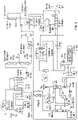
- FIG. 1 is a conceptual diagram of an example cooling water monitoring and control system 100.
- System 100 includes a cooling tower 102, one or more heat exchanges 104, and a pump 106 that can introduce one or more chemical agents into a cooling water stream being recirculated through the heat exchange network.
- a comparatively hot process stream and a comparatively cold cooling water stream can be passed through heat exchanger 104.
- the fluids may be separated by a solid wall surface within the heat exchanger to prevent mixing of the fluids.
- Thermal energy can transfer from the comparatively hot process stream to the comparatively cold cooling water stream, resulting in a reduction in the temperature of the process stream and an increase in the temperature of the cooling water stream. While the example system of FIG.
- a heat exchange network utilizing the concepts of the present disclosure may include multiple heat exchangers (e.g., each configured as heat exchanger 104 is described) that a cooling water stream flows through in series or in parallel.
- Heat exchanger 104 in the example of FIG. 1 includes a cooling water inlet 108 and a cooling water outlet 110.
- the heat exchanger also includes a process stream inlet 112 and process stream outlet 114.
- a cooling water stream 116 can enter heat exchanger 104 through the cooling water inlet 108, flow through one or more divided pathways inside of the heat exchanger, and exit the heat exchanger through the cooling water outlet 110.
- a process stream 118 can enter heat exchanger 104 through the process stream inlet 112, flow through one or more divided pathways inside of the heat exchanger that are separated from the cooling water stream, and exit the heat exchanger through process stream outlet 114.
- the cooling water stream and the process stream flow in a co-current directions through the heat exchanger.
- heat exchanger 104 can be implemented using any desired type of heat exchanger design, such as a shell and tube heat exchanger, a plate heat exchanger, or other type of thermal transfer device.
- cooling water stream 116 is delivered to heat exchanger 104 from an upstream cooling tower 102 and recycled back to the cooling tower after passing through the heat exchanger.
- cooling water stream 116 may pass through one or more heat exchangers before entering heat exchanger 104 and/or through one or more heat exchangers after passing through heat exchanger 104 before returning to cooling tower 102.
- thermal energy transferred to the cooling water stream flowing through the heat transfer circuit can be removed and discharged to atmosphere.
- cooling tower 102 may bring the cooling water stream in direct contact with air, resulting in a reduction in the temperature the cooling water stream through evaporative cooling.
- the cooling water may be delivered to a sump or reservoir before being drawn out and passed through the heat exchange network.
- cooling water may be periodically removed from the heat exchange system.
- a discharge line 120 can be used to "bleed-off a portion of the sump or reservoir water while the system is operating, or a “blow down” can be performed, which is typically a complete draining of the sump.
- a "make-up" water line 122 can supply fresh water to the cooling system to make for water losses through evaporation or deliberate dumping.
- heat exchanger 104 may impact the thermal performance of heat exchanger 104 from the cooling water side of the heat exchanger. For example, if the cooling water contains a high level of solids (e.g., silt, debris) the solids may partially or fully plug the cooling water fluid pathway through heat exchanger 104. As an example, the cooling water may cause deposits to form on the internal surfaces of heat exchanger 104 contacted by the cooling water.
- solids e.g., silt, debris
- the evaporation of cooling water can lead to the concentration of salts (e.g., calcium, sodium, magnesium) in the cooling water stream recycled through the system. These salts can form scaling deposits on surfaces of heat exchanger 104 contacted by the cooling water.
- salts e.g., calcium, sodium, magnesium
- biofilms can deposit on surfaces of heat exchanger 104 contacted by the cooling water.
- corrosion products can develop within the cooling water stream, e.g., due to the oxidation of metal component (e.g., iron, aluminum, and/or zinc). These corrosion products can also deposit on surfaces of heat exchanger 104 contacted by the cooling water. Independent of the mechanism or cause of the fouling, a build-up of a barrier layer on the surfaces of heat exchanger 104 contacted by the cooling water can reduce the efficacy of thermal transfer through the heat exchanger.
- system 100 includes a pump 106 fluidly connected to a chemical additive reservoir 124.
- Pump 106 can operate to add one or more chemicals to the cooling water that are selected to inhibit the formation and/or deposition of foulants on surfaces contacted by the cooling water.
- Example chemical additives that may be injected into the cooling water include, but are not limited to, a polymer (scale inhibitor), an organophosphorus compound such as zinc polyphosphate, zinc orthophosphate, and/or zinc organo-phosphorous compound (scale and corrosion inhibitors), and a biocide.
- one or more chemical additives may be injected into the cooling water to adjust the pH of the cooling water.
- pH adjusting compounds include mineral acids, organic acids, and inorganic bases.
- pump 106 is illustrated as adding chemical additive to the cooling water between cooling tower 102 and heat exchanger 104.
- the chemical additive may be introduced to the cooling water stream at any suitable location, such as a sump associated with the cooling tower.
- system 100 in FIG. 1 illustrates a single pump 106 fluidly coupled to a single chemical additive reservoir 124
- pump 106 may be in selective fluid communication with multiple reservoirs containing different chemicals and/or system 100 may include multiple pumps each configured to introduce a different chemical into the cooling water.
- the type of chemical introduced into the cooling water can be changed based on changing conditions of the cooling water.
- the thermal performance of heat exchanger 104 may be monitored.
- the thermal performances of heat exchanger 104 may be monitored to evaluate the efficiency with which thermal energy is transferring from the comparatively hot process stream to the comparatively cold cooling water stream.
- the heat transfer efficiency of heat exchanger 104 may greatest when the heat exchanger is initially cleaned.
- heat exchanger 104 may be periodically cleaned using chemical and/or mechanical cleaning implements to remove fouling on the process and/or cooling side of the exchanger, providing heat exchange surfaces of the heat exchanger are clean and substantially or entirely unfouled. Over time in service, fouling deposits may build up on the process stream side and/or cooling water stream side of the heat exchanger heat transfer surfaces. As a result, the heat transfer efficiency of heat exchanger 104 may deteriorate during the course of service from one cleaning to the next cleaning.
- system 100 includes a temperature sensor 126 that measures a temperature of cooling water stream 116 and 3 heat exchanger 104 and a temperature sensor 128 measuring a temperature of the cooling water stream exiting the heat exchanger.
- the system also includes a temperature sensor 130 measuring the temperature of the process stream 118 entering heat exchanger 104, and a temperature sensor 132 measuring the temperature the process stream exiting the heat exchanger.
- temperature sensors are illustrated schematically as being positioned immediately adjacent heat exchanger 104, the temperature sensors may be positioned at an upstream or downstream location from the heat exchanger, provided the temperature sensors provide a suitably accurate measure of the temperature of the respective stream entering or exiting the heat exchanger.
- System 100 may include additional and/or different sensors to measure different operational parameters of heat exchanger 104.
- the system may include one or more flow sensors to measure the flow rate of cooling water stream 116 and/or process stream 118.
- system 100 shows a flow sensor 134 positioned to measure a flow rate of the cooling water stream exiting heat exchanger 104.
- the flow rates of the cooling water stream 116 and/or process stream 118 may be determined based on pump speeds or other information within the operating environment indicating the amount of fluid conveyed through the heat exchanger.
- sensors that may be usefully employed in system 100 include pressure sensors (e.g., to measure a differential pressure of the cooling water stream and/or process stream across the heat exchanger), an oxidation-reduction potential (ORP) sensor to measure the ORP of the cooling water, a pH sensor to measure the pH of the cooling water, and/or a conductive sensor to measure the conductivity of the cooling water.
- pressure sensors e.g., to measure a differential pressure of the cooling water stream and/or process stream across the heat exchanger
- ORP oxidation-reduction potential
- pH sensor to measure the pH of the cooling water
- a conductive sensor to measure the conductivity of the cooling water.
- System 100 in the example of FIG. 1 also includes controller 136.
- Controller 136 can be communicatively connected to the sensor components and controllable components of system 100 to manage the overall operation of the system.
- controller 136 can be communicatively connected to pump 106, cooling water inlet temperature sensor 126, cooling water outlet temperature sensor 128, process stream inlet temperature sensor 130, process stream outlet temperature sensor 132, and flow sensor 134.
- Controller 136 includes processor 138 and memory 140. Controller 136 communicates with communicatively connected components via a wired or wireless connection, which in the example of FIG. 1 is illustrated as a wired connection. Controls signals sent from controller 136 and received by the controller can travel over the connection.
- Memory 140 stores software for running controller 136 and may also store data generated or received by processor 138, e.g., from temperature sensors 126, 128, 130, 132, and flow sensor 134. Processor 138 runs software stored in memory 140 to manage the operation of system 100.
- Controller 136 may be implemented using one or more controllers, which may be located at the facility site containing heat exchanger 104. Controller 136 may communicate with one or more remote computing devices 142 via a network 144. For example, controller 136 may communicate with a geographically distributed cloud computing network, which may perform any or all of the functions attributed to controller 136 in this invention.
- Network 144 can be configured to couple one computing device to another computing device to enable the devices to communicate together.
- Network 144 may be enabled to employ any form of computer readable media for communicating information from one electronic device to another.
- network 144 may include a wireless interface, and/or a wired interface, such as the Internet, in addition to local area networks (LANs), wide area networks (WANs), direct connections, such as through a universal serial bus (USB) port, other forms of computer-readable media, or any combination thereof.
- LANs local area networks
- WANs wide area networks
- USB universal serial bus
- a router may act as a link between LANs, enabling messages to be sent from one to another.
- Communication links within LANs may include twisted wire pair or coaxial cable, while communication links between networks may utilize analog telephone lines, full or fractional dedicated digital lines, Integrated Services Digital Networks (ISDNs), Digital Subscriber Lines (DSLs), wireless links including cellular and satellite links, or other communications links.
- ISDNs Integrated Services Digital Networks
- DSLs Digital Subscriber Lines
- wireless links including cellular and satellite links, or other communications links.
- remote computers and other related electronic devices may be remotely connected to either LANs or WANs via a modem and temporary telephone link.
- temperature sensors 126, 128, 130, and 132 can generate data indicative of a temperature of a respective fluid stream entering or exiting heat exchanger 104.
- flow sensor 134 can generate data indicative of a flow rate of cooling water exiting heat exchanger 104.
- Controller 136 can receive data from the sensors deployed throughout system 100 and use data generated by the sensors to determine a heat transfer efficiency of heat exchanger 104. With reference to information stored in memory relating received temperature information and/or flow rate information to heat transfer efficiency values, controller 136 can determine heat transfer efficiency values for the heat exchanger.
- controller 136 can determine the heat transfer efficiency of heat exchanger 104 using Equation (1) below: U ⁇ Value : m ⁇ C p ⁇ T water ⁇ T LMTD ⁇ Heat Tr . Area ⁇ F t
- Equation (1) above U-Value is the heat transfer efficiency
- m is the mass of the cooling water stream per unit time
- C p is the specific heat of the cooling water stream
- ⁇ T water is a difference between the temperature of the cooling water stream exiting the heat exchanger and the temperature of the cooling water stream entering a heat exchanger
- Heat Tr. Area is an amount of surface area of the heat exchanger over which thermal energy is transferred between the process stream and the cooling water stream
- F t is a correction factor corresponding to a geometry of the heat exchange
- ⁇ T LMTD is a log-mean temperature difference.
- Parameters such as the specific heat of the cooling water stream, the heat transfer area of heat exchanger 104, and a correction factor, may be stored in a memory and/or calculable based on information stored in memory.
- a user may use a user input device to store information in memory 140 of controller 136 corresponding to the specific heat of the cooling water stream (e.g., the specific heat of water), and characteristics corresponding to the geometry of heat exchanger 104.
- Equation (1) above may be calculated using Equation (2) or (3) below.
- Equation (2) may be used in circumstances where the cooling water stream and the process stream flow in a counter-current direction.
- Equation (3) may be used in circumstances where the cooling water stream and the process stream flow in a co-current direction.
- T Process,in is the temperature of the process water stream entering the heat exchanger as measured by temperature sensor 130
- T Process, out is the temperature of the process stream exiting the heat exchanger as measured by temperature sensor 132
- t water in is the temperature of the cooling water stream entering the heat exchanger as measured by temperature sensor 126
- t water, out is the temperature of the cooling water stream exiting the heat exchanger, as measured by temperature sensor 128.
- Controller 136 may receive data from the sensors in system 100 and determine the heat transfer efficiency of heat exchanger 104 continuously or on a periodic basis. For example, controller 136 may determine the heat transfer efficiency of heat exchanger 104 at least once per day, such as at least once per hour, at least once per minute, or at least once per second. The frequency with which controller 136 calculates the heat transfer efficiency of heat exchanger 104 may vary depending on the sampling rate of the sensors in system 100, the processing capacity of controller 136, and/or an operator input selecting the frequency with which the heat transfer efficiency should be calculated.
- heat exchanger 104 exhibits a high heat transfer efficiency that remains high (e.g., substantially constant) during the service interval of the heat exchanger.
- the heat transfer efficiency of heat exchanger 104 may decrease over time as fouling builds up on the process stream side of the heat exchanger and/or on the cooling water side of the heat exchanger.
- interventional action may be taken on the cooling water side by controlling pump 106 to control the addition of one or more chemical additives to the cooling water stream in response to detecting changes in thermal efficiency.
- controller 136 establishes a heat transfer efficiency trend for heat exchanger 104 over a period of time.
- the period of time over which the heat transfer efficiency trend is established may begin when the heat exchanger is first placed in service (e.g., is new or following cleaning). This is when heat exchanger 104 is least likely to be fouled.
- the period of time over which the heat transfer efficiency trend is established may begin after the heat exchanger has been placed in service for a period of time.
- the heat transfer efficiency trend may be begin when changes are made to the cooling water stream (e.g., following blow down) and/or changes are made to the process stream (e.g., change in temperature, pressure, composition) flowing through heat exchanger 104.
- controller 136 may measure the heat transfer efficiency for a period of time effective to provide a statistically reasonable trend of the heat transfer efficiency behavior. For example, controller 136 may measure the heat transfer efficiency of heat exchanger 104 for at least 5 days, such as at least 10 days, at least 20 days, or at least 30 days. In some examples, controller 136 measures the heat transfer efficiency of heat exchanger 104 for a period of time ranging from 5 days to 100 days, such as from 10 days to 45 days. In some examples, controller 136 measures the heat transfer efficiency as a rolling average over a certain number of preceding days, such as a proceeding period ranging from 5 days to 50 days.
- Controller 136 can generate heat transfer efficiency values based on sensor information received during the period of measurement. Controller 136 can further perform statistical trend analysis on the heat transfer efficiency values determined during the period of measurement to identify a trend for the heat transfer efficiency of heat exchanger 104.
- controller 136 may fit a curve to heat transfer efficiency values plotted on a y-axis of a graph with corresponding measurement time plotted on the x-axis of the graph.
- the slope of the curve "m" can be stored in a memory associated with controller 136 as a trend corresponding to heat transfer efficiency of heat exchanger 104. In other examples, a higher order polynomial curve may be fit to the data.
- controller 136 processes the temperature data received from sensors 126, 128, 130, and 132 and/or flow data received from sensor 134 prior to calculating the heat transfer efficiency. For example, controller 136 may smooth the data using a statistical smoothing algorithm to remove noise and outliers from the data. Controller 136 may then determine the heat transfer efficiency using smoothed temperature values. Alternatively, controller 136 may calculate heat transfer efficiency values for the raw data and apply the smoothing algorithm to the calculated heat transfer efficiency values. Subsequent trend analysis and change detection may be performed using the smoothed data.
- Controller 136 can continue receiving measurements from the sensors in system 100 and generating heat transfer efficiency values based on the received sensor data after establishing a heat transfer efficiency trend. Controller 136 can compare heat transfer efficiency information for heat exchanger 104 to the heat transfer efficiency trend determined for the heat exchanger and detect if there is a change in the heat transfer efficiency trend. For example, controller 136 may determine a heat transfer efficiency trend for a measurement period and compare that trend to the earlier-established trend. The measurement period can be comparatively short (e.g., a day or less) or longer (e.g., a day or more, such as a week or more).
- controller 136 may determine a slope of the heat transfer efficiency during the measurement period. Controller 136 may compare the slope of the heat transfer efficiency trend of heat exchanger 104 during the measurement period to slope of the earlier-established heat transfer efficiency trend.
- Controller 136 may determine if the heat transfer efficiency trend during the measurement period differs from the earlier-established heat transfer efficiency trend by more than a threshold amount.
- the threshold amount may be greater than or equal to 1% of the earlier-established heat transfer efficiency value (e.g., slope), such as greater than or equal to 5% of the earlier-established heat transfer efficiency value, greater than or equal to 10% of the earlier-established heat transfer efficiency value, greater than or equal to 25% of the earlier-established heat transfer efficiency value, or greater than or equal to 50% of the earlier-established heat transfer efficiency value.
- the threshold amount may range from 1 percent to 25 percent of the earlier-established heat transfer efficiency value, such as from 5 percent to 20 percent.
- the heat transfer efficiency trend is deviating from the earlier-established heat transfer efficiency trend, it may be indicative that the heat exchanger is fouling faster during the measurement period than during earlier operation. If left untreated, the more rapid fouling may reduce the operating efficiency of heat exchanger 104, potentially necessitating costly and unplanned shutdown to clean the exchanger before the next scheduled cleaning.
- controller 136 can control pump 106 to control the addition of chemical additive to the cooling water in response to the detected change in heat transfer efficiency trend.
- Processor 138 of controller 136 may compare the change in heat transfer efficiency trend to one or more thresholds stored in memory 140 relating different efficiency trend changes to different additive control schemes.
- controller 136 starts and/or stops pump 106 or increases and/or decreases the rate of pump 106 to adjust the concentration of a chemical additive in the cooling water. Starting pump 106 or increasing the operating rate of pump 106 can increase the concentration of the chemical additive in the cooling water. This may be useful if the detected change indicates that the heat transfer efficiency trend has deviated negative, meaning heat exchanger 104 is fouling faster than earlier detected.
- Stopping pump 106 or decreasing the operating rate of pump 106 may decrease the concentration of chemical additive in the cooling water. This may be useful if the detected change indicates that the heat transfer efficiency trend has deviated positive, meaning heat exchanger 104 is fouling slower than earlier detected such that less additive can be used.
- controller 136 may select one or more of the different chemical additives to be introduced into the cooling water based on the detected change in heat transfer efficiency trend. Controller 136 may select one or more different chemical additives by controlling valve(s) and/or pump(s) fluidly coupling the one or more different chemical additives to the cooling water stream. For example, controller 136 may vary the type of chemical additive introduced into the cooling water and/or the rate at which the chemical additive is introduced into the cooling water based on the detected change in heat transfer efficiency trend and, optionally, also based on other sensor data, such as ORP, pH, and/or conductivity of the cooling water.
- controller 136 starts pump 106 or increasing the operating rate of pump 106 in response to detecting a change indicating that the heat transfer efficiency trend for heat exchanger 104 has decreased by more than a threshold amount compared to the earlier-established heat transfer efficiency trend. Controller 136 can continue receiving data from the sensors in system 100 and calculating a heat transfer efficiency for heat exchanger 104 after adjusting the chemical additive introduced into the cooling water. Controller 136 may monitor the heat transfer efficiency trend for heat exchanger 104 following changes made to the chemical additive (e.g., type and/or rate) in response to detecting a change to the heat transfer efficiency trend.
- the chemical additive e.g., type and/or rate
- Controller 136 may determine if the heat transfer efficiency trend stabilizes (e.g., remains substantially constant), returns toward the previously-established trend, or deviates further from the previously-established trend. Controller 136 may control system 100 to further modify the type and/or rate of chemical additive introduced into the cooling water based on the continue monitoring of the heat transfer efficiency. For example, controller 136 may increase the amount of chemical additive in the cooling water (e.g., by starting or increasing the rate of pump 106), at least until the heat transfer efficiency trend for heat exchanger 104 exhibits an inflection point. The inflection point may correspond to a change from a downward trend for the heat transfer efficiency (e.g., indicating that the rate of fouling is increasing) to an upward trend (e.g., indicating that rate of fouling is decreasing).
- Controller 136 may take a variety of different control actions within system 100 in addition to or in lieu of controlling pump 106 to change a type or concentration of chemical additive in the cooling water. As one example, controller 136 may increase the rate at which cooling water flows through heat exchanger 104 in response to detecting a change in the heat transfer efficiency trend for the heat exchanger. For example, if controller 136 detects a sudden change in the absolute magnitude of the heat transfer efficiency of heat exchanger 104 and/or a significant decrease in the heat transfer efficiency trend (e.g., indicating rapid fouling), that may be indicative of heat exchanger plugging due to silt, debris, or other large particulate matter.
- controller 136 may increase the rate at which cooling water flows through heat exchanger 104 in response to detecting a change in the heat transfer efficiency trend for the heat exchanger. For example, if controller 136 detects a sudden change in the absolute magnitude of the heat transfer efficiency of heat exchanger 104 and/or a significant decrease in the heat transfer efficiency trend (e.g., indicating rapid
- Controller 136 may control a pump (not illustrated) supplying cooling water from a sump associated with cooling tower 102 to heat exchanger 104 to control the flow rate of cooling water supply to the heat exchanger.
- a cooling water monitoring and control system can be implemented in any process where a thermal exchange fluid is used to transfer thermal energy with one or more process streams through a heat exchanger.
- Example process streams that may flow through the hot side of heat exchanger 104 include, but are not limited to, crude oil, derivatives of crude oil (e.g., refined or partially refined crude oil products), and intermediary or final products in an ammonia production process.
- the process streams flowing through the hot side of heat exchanger 104 may generally be liquid phase, although may be vapor phase, and/or a liquid-vapor multi-phase stream.
- FIG. 1 illustrates an example monitoring and control system containing only a single heat exchanger
- example applications may include multiple heat exchangers in series and/or in parallel.
- FIG. 2 is a flow diagram illustrating an example heat exchanger network containing multiple heat exchangers in which a cooling water monitoring and control system according to the invention may be implemented.
- multiple heat exchangers 104A-104D are fluidly connected to a cooling water stream supplied by cooling tower 102. Cooling water flows in parallel through heat exchangers 104A and 104B followed, in series, through heat exchangers 104C-104E before returning to the cooling tower.
- one or multiple of the heat exchangers may include sensors as described in connection with heat exchanger 104 in FIG. 1 .
- Controller 136 can receive data from the sensors and determine a heat transfer efficiency trend for each of the connected heat exchangers. Controller 136 can detect a change in the heat transfer efficiency trend of at least one, and optionally multiple, of the heat exchangers being monitored and control addition of the chemical additive to the cooling water stream based on the detected trend.
- controller 136 may control pump 106 to change the type and/or amount of chemical additive introduced into the cooling water stream upon detecting a change in the heat transfer efficiency trend (e.g., exceeding a threshold amount) of a single heat exchanger.
- controller 136 may control pump 106 to change the type and/or amount of chemical additive introduced into the cooling water stream upon detecting a change in the heat transfer efficiency trend (e.g., exceeding a threshold amount) of multiple of the heat exchangers.
- the detection of changed heat transfer efficiency trends for multiple heat exchangers may indicate the fouling conditions are actually changing as opposed to receiving errant sensor data from one particular heat exchanger.
- FIG. 3 is a flow diagram illustrating an example ammonia production process.
- the example process includes multiple cooling heat exchangers through which cooling water may be conveyed.
- One or more (e.g., all) of these example heat exchangers may be monitored using the techniques and systems described herein, and chemical additive to the cooling water stream controlled based on the heat exchanger efficiency trends.
- processors including one or more microprocessors, digital signal processors (DSPs), application specific integrated circuits (ASICs), field programmable gate arrays (FPGAs), or any other equivalent integrated or discrete logic circuitry, as well as any combinations of such components.
- DSPs digital signal processors
- ASICs application specific integrated circuits
- FPGAs field programmable gate arrays
- processors may generally refer to any of the foregoing logic circuitry, alone or in combination with other logic circuitry, or any other equivalent circuitry.
- a control unit comprising hardware may also perform one or more of the techniques of this invention.
- Such hardware, software, and firmware may be implemented within the same device or within separate devices to support the various operations and functions described in this invention.
- any of the described units, modules or components may be implemented together or separately as discrete but interoperable logic devices. Depiction of different features as modules or units is intended to highlight different functional aspects and does not necessarily imply that such modules or units must be realized by separate hardware or software components. Rather, functionality associated with one or more modules or units may be performed by separate hardware or software components, or integrated within common or separate hardware or software components.
- the techniques described in this invention may also be embodied or encoded in a computer-readable medium, such as a non-transitory computer-readable storage medium, containing instructions. Instructions embedded or encoded in a computer-readable storage medium may cause a programmable processor, or other processor, to perform the method, e.g., when the instructions are executed.
- Non-transitory computer readable storage media may include volatile and/or non-volatile memory forms including, e.g., random access memory (RAM), read only memory (ROM), programmable read only memory (PROM), erasable programmable read only memory (EPROM), electronically erasable programmable read only memory (EEPROM), flash memory, a hard disk, a CD-ROM, a floppy disk, a cassette, magnetic media, optical media, or other computer readable media.
- RAM random access memory
- ROM read only memory
- PROM programmable read only memory
- EPROM erasable programmable read only memory
- EEPROM electronically erasable programmable read only memory
- flash memory e.g., a hard disk, a CD-ROM, a floppy disk, a cassette, magnetic media, optical media, or other computer readable media.
- the temperature in degrees Fahrenheit can be converted to a temperature in Kelvin (K) by adding a value of 459.67 to the given value and multiplying the result by 5/9.
- Temperature sensors were installed on a heat exchanger in an ammonia plant to measure the inlet and outlet temperatures of the flow streams to the heat exchanger as well as the flow rate of cooling water through the inlet of the heat exchanger.
- the heat exchanger was a syngas cooler that passed syngas through the hot or process side of the heat exchanger while cooling water flowed through the cold side of the heat exchanger.
- the heat exchanger was a counter-current shell-and-tube exchanger. The syngas was supplied to the shell side of the heat exchanger at a target flow rate of approximately 99,000 lb/hr, while the cooling water was supplied at a target flow rate of approximately 1,000,000 lb/hr.
- the cooling water was supplied from a cooling tower that had a recirculation rate of approximately 80,000 gallons/minute.
- the cooling tower had a capacity of approximately 500,000 gallons and exhibited a temperature differential of 12 degrees Fahrenheit.
- the cooling water exhibited a FRC of 0.5 ppm as Cl 2 .
- the cooling water was initially controlled with a combination of three chemical additives: a corrosion inhibitor (Nalco ® 3DT129) provided at a concentration of 35 ppm, a scale inhibitor (Nalco ® 3DT191) provided at a concentration of 75 ppm, and a yellow metal inhibitor (Nalco ® 3DT199) provided at a concentration of 10 ppm.
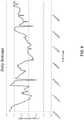
- FIG. 4 is a graph of the cooling water inlet temperature (degrees Fahrenheit) versus time showing the raw measurement data 200 along with smoothed data 202 overlaid.
- FIG. 5 is a graph of the cooling water outlet temperature (degrees Fahrenheit) versus time showing the raw measurement data 204 along with smoothed data 206 overlaid.
- FIG. 6 is a graph of the process stream inlet temperature (degrees Fahrenheit) versus time showing the raw measurement data 208 along with smoothed data 210 overlaid.
- FIG. 7 is a graph of the process stream outlet temperature (degrees Fahrenheit) versus time showing the raw measurement data 212 along with smoothed data 214 overlaid.
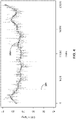
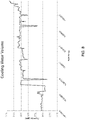
- FIG. 8 is a graph showing cooling water flow rates (gallons per minute) for an example period of time.
- FIG. 9 is a graph showing heat transfer coefficients calculated using the smoothed temperature data over the example period of time. The sharp valleys in these data correspond to when water flowrate was decreased.
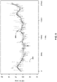
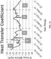
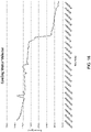
- FIG. 10 shows heat transfer coefficients calculated for the heat exchanger based on received temperature and flow rate data over an example range of dates.
- FIG. 11 shows the oxidation-reduction potential (ORP) for the cooling water stream over the same example range of dates, which is indicative of the concentration of chemical additive in the cooling water.
- ORP oxidation-reduction potential
- the cooling water was evaluated and microbial biofoulants suggested as the cause of the fouling.
- biocide dosage was increased to the cooling water, resulting in an increase in the heat transfer coefficient. To understand if this heat transfer improvement was in response to biocide dosage increase initiated upon detecting the changing trend in the heat transfer coefficient or some other factor, the biocide dosage was decreased in phase 5. The data show that the heat transfer coefficient again decreased.
- Temperature sensors were installed on a heat exchanger in a vinyl plant to measure the inlet and outlet temperatures of the flow streams to the heat exchanger as well as the flow rate of cooling water through the inlet of the heat exchanger.
- the heat exchanger had a propylene stream passing through the hot or process side of the heat exchanger while cooling water flowed through the cold side of the heat exchanger.
- the heat exchanger was a counter-current shell-and-tube exchanger. The propylene was supplied to the shell side of the heat exchanger at a target flow rate of approximately 270,000 lb/hr, while the cooling water was supplied at a target flow rate of approximately 4,600,000 lb/hr.
- the cooling water was supplied from a cooling tower that had a recirculation rate of approximately 85,000 gallons/minute.
- the cooling tower had a capacity of approximately 1,000,000 gallons and exhibited a temperature differential of 10 degrees Fahrenheit.
- the cooling water exhibited a FRC of 0.5 ppm as Cl 2 .
- the cooling water was initially controlled with a combination of three chemical additives: a corrosion inhibitor (Nalco ® 3DT177) provided at a concentration of 37 ppm, a scale inhibitor (Nalco ® 3DT390) provided at a concentration of 28 ppm, and a yellow metal inhibitor (Nalco ® 3DT197) provided at a concentration of 10 ppm.
- FIG. 12 is a graph of the cooling water inlet temperature (degrees Fahrenheit) versus time showing the raw measurement data 220 along with smoothed data 222 overlaid.
- FIG. 13 is a graph of the cooling water outlet temperature (degrees Fahrenheit) versus time showing the raw measurement data 224 along with smoothed data 226 overlaid.
- FIG. 14 is a graph of the process stream inlet temperature (degrees Fahrenheit) versus time showing the raw measurement data 228 along with smoothed data 230 overlaid.
- FIG. 12 is a graph of the cooling water inlet temperature (degrees Fahrenheit) versus time showing the raw measurement data 220 along with smoothed data 222 overlaid.
- FIG. 13 is a graph of the cooling water outlet temperature (degrees Fahrenheit) versus time showing the raw measurement data 224 along with smoothed data 226 overlaid.
- FIG. 14 is a graph of the process stream inlet temperature (degrees Fahrenheit) versus time showing the raw measurement data 228
- FIG. 15 is a graph of the process stream outlet temperature (degrees Fahrenheit) versus time showing the raw measurement data 232 along with smoothed data 234 overlaid.
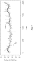
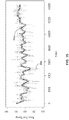
- FIG. 16 is a graph showing cooling water flow rates (gallons per minute) for an example period of time. The step change in water flow rate was caused by an intentional decrease in the water flow.
- FIG. 17 is a graph showing heat transfer coefficients calculated using the smoothed temperature data over the example period of time.
- the heat transfer coefficient trend during the period of measurement was substantially flat.
- cooling water flow rates were observed to progressively decrease during the period of monitoring.
- This combination of behavior suggested debris/silting in the heat exchanger which would not be effectively addressed through chemistry addition alone. Rather, flushing of the heat exchanger and/or exchanger clean out may be needed to remove the accumulated debris/silting. This conclusion from the data was confirmed during a plant outage when the heat exchanger was opened and visually inspected.
Landscapes
- Engineering & Computer Science (AREA)
- Life Sciences & Earth Sciences (AREA)
- Chemical & Material Sciences (AREA)
- Environmental & Geological Engineering (AREA)
- Hydrology & Water Resources (AREA)
- Water Supply & Treatment (AREA)
- Organic Chemistry (AREA)
- Mechanical Engineering (AREA)
- General Engineering & Computer Science (AREA)
- Physics & Mathematics (AREA)
- Thermal Sciences (AREA)
- Environmental Sciences (AREA)
- General Physics & Mathematics (AREA)
- Biodiversity & Conservation Biology (AREA)
- Health & Medical Sciences (AREA)
- Analytical Chemistry (AREA)
- Biochemistry (AREA)
- General Health & Medical Sciences (AREA)
- Ecology (AREA)
- Immunology (AREA)
- Pathology (AREA)
- Combustion & Propulsion (AREA)
- Heat-Exchange Devices With Radiators And Conduit Assemblies (AREA)
- Air Conditioning Control Device (AREA)
- Testing And Monitoring For Control Systems (AREA)
- Sorption Type Refrigeration Machines (AREA)
Applications Claiming Priority (2)
| Application Number | Priority Date | Filing Date | Title |
|---|---|---|---|
| US201762560595P | 2017-09-19 | 2017-09-19 | |
| PCT/US2018/050841 WO2019060203A1 (en) | 2017-09-19 | 2018-09-13 | SYSTEM FOR MONITORING AND CONTROLLING COOLING WATER |
Publications (2)
| Publication Number | Publication Date |
|---|---|
| EP3685113A1 EP3685113A1 (en) | 2020-07-29 |
| EP3685113B1 true EP3685113B1 (en) | 2022-06-08 |
Family
ID=63714101
Family Applications (1)
| Application Number | Title | Priority Date | Filing Date |
|---|---|---|---|
| EP18779935.8A Active EP3685113B1 (en) | 2017-09-19 | 2018-09-13 | Method for cooling water monitoring and control |
Country Status (13)
| Country | Link |
|---|---|
| US (1) | US11891309B2 (es) |
| EP (1) | EP3685113B1 (es) |
| JP (1) | JP7354113B2 (es) |
| KR (1) | KR102628369B1 (es) |
| CN (1) | CN111279145B (es) |
| AU (1) | AU2018337629B2 (es) |
| BR (1) | BR112020005034B1 (es) |
| CL (1) | CL2020000696A1 (es) |
| CO (1) | CO2020003108A2 (es) |
| ES (1) | ES2928141T3 (es) |
| MX (1) | MX2020003005A (es) |
| PL (1) | PL3685113T4 (es) |
| WO (1) | WO2019060203A1 (es) |
Families Citing this family (7)
| Publication number | Priority date | Publication date | Assignee | Title |
|---|---|---|---|---|
| ES2933502T3 (es) | 2017-11-10 | 2023-02-09 | Ecolab Usa Inc | Método de control y monitoreo del agua de enfriamiento |
| CN113109390B (zh) * | 2021-05-17 | 2023-09-12 | 西安热工研究院有限公司 | 一种汽轮发电机定子冷却水化学清洗效果评价方法 |
| CN114111437B (zh) * | 2021-10-26 | 2024-07-26 | 湖南永杉锂业有限公司 | 一种换热器结垢处理系统及其控制方法 |
| JP2023067227A (ja) * | 2021-10-29 | 2023-05-16 | 荏原冷熱システム株式会社 | 水冷式冷凍機システム |
| CN114034498B (zh) * | 2021-11-05 | 2024-11-01 | 中国特种设备检测研究院 | 一种热交换器性能测试与能效评价系统 |
| TWI859572B (zh) * | 2022-08-30 | 2024-10-21 | 廣達電腦股份有限公司 | 測試裝置 |
| CN118009797B (zh) * | 2024-04-08 | 2024-06-07 | 山东光大机械制造有限公司 | 一种热交换器及其控制装置和控制方法 |
Family Cites Families (87)
| Publication number | Priority date | Publication date | Assignee | Title |
|---|---|---|---|---|
| GB770242A (en) | 1954-04-08 | 1957-03-20 | Svenska Rotor Maskiner Ab | Improvements in or relating to heat exchangers |
| SE399765B (sv) | 1974-11-15 | 1978-02-27 | Stal Laval Apparat Ab | Metapparat for metning av forsmutsningsgrad i vermevexlare och andra rorledningar |
| US4339945A (en) | 1980-10-30 | 1982-07-20 | Drew Chemical Corporation | Process and apparatus for testing fluids for fouling |
| US4383438A (en) | 1981-06-02 | 1983-05-17 | Petrolite Corporation | Fouling test apparatus |
| JPS5915800A (ja) | 1982-07-19 | 1984-01-26 | Kurita Water Ind Ltd | フアウリング防止装置 |
| KR890001890B1 (ko) | 1984-03-23 | 1989-05-30 | 더 뱁콕 앤드 윌콕스 컴퍼니 | 열교환기 성능 감지기 |
| DE353489T1 (de) | 1988-07-25 | 1990-06-13 | Nalco Chemical Co., Naperville, Ill. | Automatisiertes lagerhaltungs- und verteilsystem fuer chemikalien. |
| JP2764046B2 (ja) | 1988-12-13 | 1998-06-11 | 株式会社日阪製作所 | プレート式熱交換器 |
| US5085831A (en) | 1989-10-17 | 1992-02-04 | Nalco Chemical Company | Apparatus for continually and automatically measuring the level of a water treatment product in boiler feedwater |
| JP2675684B2 (ja) | 1990-05-10 | 1997-11-12 | 株式会社東芝 | 熱交換器の異常監視装置 |
| US5171450A (en) * | 1991-03-20 | 1992-12-15 | Nalco Chemical Company | Monitoring and dosage control of tagged polymers in cooling water systems |
| JPH0820144B2 (ja) * | 1991-05-23 | 1996-03-04 | 株式会社荏原製作所 | 冷凍機用凝縮器の運転方法 |
| US5278074A (en) | 1992-04-22 | 1994-01-11 | Nalco Chemical Company | Method of monitoring and controlling corrosion inhibitor dosage in aqueous systems |
| US5273687A (en) | 1992-12-09 | 1993-12-28 | Baltimore Aircoil Company | Microbiological control of recirculating water in evaporative cooling systems at idle conditions |
| JPH06330747A (ja) | 1993-05-26 | 1994-11-29 | Kubota Corp | インライン形熱交換器の診断方法 |
| US5429178A (en) | 1993-12-10 | 1995-07-04 | Electric Power Research Institute, Inc. | Dual tube fouling monitor and method |
| US5603840A (en) | 1995-05-15 | 1997-02-18 | Nalco Chemical Company | Method of achieving microbiological control in open recirculating cooling water |
| US5855791A (en) | 1996-02-29 | 1999-01-05 | Ashland Chemical Company | Performance-based control system |
| US5734098A (en) | 1996-03-25 | 1998-03-31 | Nalco/Exxon Energy Chemicals, L.P. | Method to monitor and control chemical treatment of petroleum, petrochemical and processes with on-line quartz crystal microbalance sensors |
| JP2000028557A (ja) | 1998-07-15 | 2000-01-28 | Tlv Co Ltd | 熱交換器の汚れ検出装置 |
| US6419817B1 (en) | 2000-06-22 | 2002-07-16 | United States Filter Corporation | Dynamic optimization of chemical additives in a water treatment system |
| US6454995B1 (en) | 2000-08-14 | 2002-09-24 | Ondeo Nalco Energy Services, L.P. | Phosphine coke inhibitors for EDC-VCM furnaces |
| US6556027B2 (en) | 2001-01-12 | 2003-04-29 | Ondeo Nalco Company | Low cost, on-line corrosion monitor and smart corrosion probe |
| US6739290B2 (en) | 2001-03-06 | 2004-05-25 | Calsonic Kansei Corporation | Cooling system for water-cooled internal combustion engine and control method applicable to cooling system therefor |
| US6581409B2 (en) | 2001-05-04 | 2003-06-24 | Bechtel Bwxt Idaho, Llc | Apparatus for the liquefaction of natural gas and methods related to same |
| US6740231B1 (en) | 2001-07-11 | 2004-05-25 | Nalco Company | Self-contained cooling system feed and bleed system |
| US20040254682A1 (en) | 2001-12-27 | 2004-12-16 | Tim Kast | Apparatus, system and method for non-chemical treatment and management of cooling water |
| US7146231B2 (en) | 2002-10-22 | 2006-12-05 | Fisher-Rosemount Systems, Inc.. | Smart process modules and objects in process plants |
| CA2437264C (en) | 2003-08-12 | 2013-12-03 | Brian Wilson Varney | Heat exchanger optimization process and apparatus |
| US7455099B2 (en) * | 2003-12-19 | 2008-11-25 | General Electric Company | Heat exchanger performance monitoring and analysis method and system |
| JP2005300404A (ja) | 2004-04-14 | 2005-10-27 | Japan Science & Technology Agency | 電気泳動用ゲル作製器具 |
| DE102004021423A1 (de) | 2004-04-30 | 2005-12-01 | Siemens Ag | Verfahren und Einrichtung zur Ermittlung der Leistungsfähigkeit eines Wärmetauschers |
| US7866211B2 (en) | 2004-07-16 | 2011-01-11 | Rosemount Inc. | Fouling and corrosion detector for process control industries |
| US7110906B2 (en) | 2004-07-22 | 2006-09-19 | Abb Inc. | System and method for monitoring the performance of a heat exchanger |
| WO2006105369A1 (en) | 2005-03-31 | 2006-10-05 | Ashland Licensing And Intellectual Property Llc | Process for inhibiting biofilm formation on and/or removing biofilm from an enhanced tube |
| JP2006300404A (ja) * | 2005-04-20 | 2006-11-02 | Mitsubishi Heavy Ind Ltd | スケールの除去方法 |
| CN1731068B (zh) | 2005-08-01 | 2010-05-12 | 东北电力学院 | 管侧对流换热强化技术动态模拟综合评价方法及装置 |
| KR100652249B1 (ko) | 2005-12-26 | 2006-12-01 | 주식회사 성지공조기술 | 냉각탑 제어시스템 |
| BRPI0601967B1 (pt) | 2006-06-01 | 2021-03-23 | Embraco Indústria De Compressores E Soluções Em Refrigeração Ltda. | Sistema e método de controle de operação de um sistema de refrigeração |
| CN100487352C (zh) | 2006-06-30 | 2009-05-13 | 王正方 | 一种无沉积水垢的板式换热器的换热方式 |
| CN101535909B (zh) | 2006-09-28 | 2012-08-29 | 费舍-柔斯芒特系统股份有限公司 | 热交换器中的异常情况预防 |
| US7428055B2 (en) | 2006-10-05 | 2008-09-23 | General Electric Company | Interferometer-based real time early fouling detection system and method |
| GB0623608D0 (en) | 2006-11-27 | 2007-01-03 | Ashe Morris Ltd | Improved monitoring system |
| FR2910546B1 (fr) | 2006-12-22 | 2009-01-23 | Renault Sas | Procede et dispositif de controle moteur selon l'encrassement du systeme de recirculation des gaz d'echappement d'un moteur diesel de vehicule automobile. |
| US7827006B2 (en) * | 2007-01-31 | 2010-11-02 | Fisher-Rosemount Systems, Inc. | Heat exchanger fouling detection |
| EP2070608B1 (en) | 2007-07-19 | 2012-09-05 | Nippon Steel Corporation | Method of cooling control, cooling control unit and cooling water quantity computing unit |
| US8489240B2 (en) | 2007-08-03 | 2013-07-16 | General Electric Company | Control system for industrial water system and method for its use |
| US8349267B2 (en) | 2007-10-05 | 2013-01-08 | Exxonmobil Research And Engineering Company | Crude oil pre-heat train with improved heat transfer |
| US20090188645A1 (en) | 2008-01-28 | 2009-07-30 | Intec, Inc | Tube fouling monitor |
| US20090277841A1 (en) | 2008-05-07 | 2009-11-12 | Johnson Donald A | Method for minimizing corrosion, scale, and water consumption in cooling tower systems |
| EP2128551A1 (de) | 2008-05-29 | 2009-12-02 | Siemens Aktiengesellschaft | Überwachung von Wärmetauschern in Prozessleitsystemen |
| US20100028202A1 (en) | 2008-07-30 | 2010-02-04 | Zhaoyang Wan | Proactive control system for an industrial water system |
| US20100163469A1 (en) | 2008-12-26 | 2010-07-01 | Zhaoyang Wan | Control system for monitoring localized corrosion in an industrial water system |
| CN101655477B (zh) | 2009-06-12 | 2012-12-05 | 东北电力大学 | 基于电导滴定的污垢特性参数检测方法及实验系统 |
| CA2710899A1 (en) * | 2009-07-23 | 2011-01-23 | H2Tronics, Inc. | Cooling tower system with chemical feed responsive to actual load |
| US8235128B2 (en) | 2009-08-18 | 2012-08-07 | Halliburton Energy Services, Inc. | Flow path control based on fluid characteristics to thereby variably resist flow in a subterranean well |
| WO2011106712A2 (en) * | 2010-02-26 | 2011-09-01 | Dominion Engineering, Inc. | Method and apparatus for evaluating repair and remediation alternatives for heat exchangers |
| WO2011144704A1 (en) | 2010-05-19 | 2011-11-24 | Voltea B.V. | Evaporative recirculation cooling water system, method of operating an evaporative recirculation cooling water system. |
| US20120018907A1 (en) * | 2010-07-23 | 2012-01-26 | Dumler Stephen E | Cooling Tower System With Chemical Feed Responsive to Actual Load |
| JP2013015259A (ja) | 2011-07-04 | 2013-01-24 | Miura Co Ltd | 水処理システム |
| PH12014502193B1 (en) * | 2012-03-28 | 2023-08-02 | Amsa Inc | Multiple uses of amine salts for industrial water treatment |
| US9689790B2 (en) | 2012-07-05 | 2017-06-27 | Honeywell International Inc. | Environmental control systems and techniques for monitoring heat exchanger fouling |
| US9521389B2 (en) | 2013-03-06 | 2016-12-13 | Qualcomm Incorporated | Derived disparity vector in 3D video coding |
| US9389000B2 (en) | 2013-03-13 | 2016-07-12 | Rheem Manufacturing Company | Apparatus and methods for pre-heating water with air conditioning unit or heat pump |
| US20160169825A1 (en) | 2013-05-17 | 2016-06-16 | Rocsole Ltd | Arrangement and method for monitoring scaling in heat exchanger |
| EP3017289B1 (en) | 2013-07-01 | 2019-11-06 | Knew Value LLC | A process for monitoring a heat exchanger |
| JP2015080780A (ja) | 2013-10-24 | 2015-04-27 | 栗田工業株式会社 | 水処理状況監視装置、水処理装置、水処理状況の監視方法、及び水処理方法 |
| CN104165529B (zh) | 2013-12-09 | 2015-08-12 | 山东大学 | 管束菱形排列的水泥回转窑余热利用换热器 |
| CN105445319B (zh) | 2014-08-29 | 2018-03-09 | 宝山钢铁股份有限公司 | 一种测定钢板表面水冷换热系数的方法及装置 |
| CN104267072A (zh) | 2014-09-04 | 2015-01-07 | 卢岳 | 一种管路水垢检测方法 |
| CN104483448B (zh) | 2014-12-02 | 2017-01-18 | 国家海洋局天津海水淡化与综合利用研究所 | 一体化移动式海水循环冷却水处理药剂评价装置和方法 |
| CN104502532B (zh) | 2014-12-02 | 2016-10-26 | 国家海洋局天津海水淡化与综合利用研究所 | 化工系统海水循环冷却水处理药剂性能评价装置和方法 |
| US10288548B2 (en) | 2015-04-17 | 2019-05-14 | Hamilton Sundstrand Corporation | Wavelet-based analysis for fouling diagnosis of an aircraft heat exchanger |
| CN104819993B (zh) | 2015-05-18 | 2018-04-03 | 河海大学 | 一种冷却水管管壁热交换系数测试装置及测试方法 |
| WO2017002081A1 (en) | 2015-07-01 | 2017-01-05 | King Abdullah University Of Science And Technology | In-situ non-invasive device for early detection of fouling in aquatic systems |
| CN105158293B (zh) | 2015-10-10 | 2017-10-31 | 中国石油化工股份有限公司 | 用于炼油装置封油水冷器传热与阻垢性能可视化测试系统 |
| CN205538771U (zh) | 2016-01-04 | 2016-08-31 | 华能南京金陵发电有限公司 | 电站锅炉水冷壁管传热特性的监测系统 |
| CN105758879B (zh) | 2016-03-02 | 2019-04-23 | 陕西省石油化工研究设计院 | 一种油田管道设备内腐蚀结垢物的分析方法 |
| CN205748090U (zh) * | 2016-05-12 | 2016-11-30 | 山东鲁亮压力容器制造有限公司 | 一种换热器自动除垢系统 |
| CN106017965B (zh) | 2016-07-12 | 2018-11-20 | 扬州大学 | 一种u型地埋管换热器热湿传递性能模拟测试装置及测试方法 |
| CN106288940A (zh) * | 2016-09-08 | 2017-01-04 | 深圳达实智能股份有限公司 | 一种制冷机冷凝器在线清洗控制方法及系统 |
| CN106932214B (zh) | 2016-12-22 | 2023-10-20 | 江苏省特种设备安全监督检验研究院 | 一种换热器性能及能效测试平台 |
| CN106872514A (zh) * | 2017-02-21 | 2017-06-20 | 沈阳艾柏瑞环境科技有限公司 | 稳态换热过程传热系数及污垢热阻值在线监测系统和方法 |
| CN206648815U (zh) | 2017-04-19 | 2017-11-17 | 山东大学 | 一种用于研究尾部烟气换热管积灰的仿真测试试验台 |
| CN106989908A (zh) | 2017-04-19 | 2017-07-28 | 山东大学 | 一种用于研究尾部烟气换热管积灰的仿真测试试验台 |
| CN107091590A (zh) * | 2017-06-17 | 2017-08-25 | 深圳市纽乐节能设备工程有限公司 | 冷凝器胶球自动在线清洗系统及方法 |
| ES2933502T3 (es) | 2017-11-10 | 2023-02-09 | Ecolab Usa Inc | Método de control y monitoreo del agua de enfriamiento |
-
2018
- 2018-09-13 MX MX2020003005A patent/MX2020003005A/es unknown
- 2018-09-13 ES ES18779935T patent/ES2928141T3/es active Active
- 2018-09-13 EP EP18779935.8A patent/EP3685113B1/en active Active
- 2018-09-13 KR KR1020207007679A patent/KR102628369B1/ko active Active
- 2018-09-13 WO PCT/US2018/050841 patent/WO2019060203A1/en not_active Ceased
- 2018-09-13 BR BR112020005034-2A patent/BR112020005034B1/pt active IP Right Grant
- 2018-09-13 PL PL18779935.8T patent/PL3685113T4/pl unknown
- 2018-09-13 US US16/130,237 patent/US11891309B2/en active Active
- 2018-09-13 JP JP2020536916A patent/JP7354113B2/ja active Active
- 2018-09-13 CN CN201880058879.1A patent/CN111279145B/zh active Active
- 2018-09-13 AU AU2018337629A patent/AU2018337629B2/en active Active
-
2020
- 2020-03-16 CO CONC2020/0003108A patent/CO2020003108A2/es unknown
- 2020-03-17 CL CL2020000696A patent/CL2020000696A1/es unknown
Also Published As
| Publication number | Publication date |
|---|---|
| JP2020534505A (ja) | 2020-11-26 |
| AU2018337629B2 (en) | 2024-02-01 |
| CN111279145A (zh) | 2020-06-12 |
| PL3685113T3 (pl) | 2022-10-03 |
| ES2928141T3 (es) | 2022-11-15 |
| MX2020003005A (es) | 2020-08-03 |
| US11891309B2 (en) | 2024-02-06 |
| PL3685113T4 (pl) | 2023-02-27 |
| CN111279145B (zh) | 2022-05-27 |
| AU2018337629A1 (en) | 2020-04-02 |
| KR102628369B1 (ko) | 2024-01-23 |
| BR112020005034A2 (pt) | 2020-09-15 |
| CO2020003108A2 (es) | 2020-04-13 |
| KR20200054975A (ko) | 2020-05-20 |
| WO2019060203A1 (en) | 2019-03-28 |
| CL2020000696A1 (es) | 2020-08-14 |
| BR112020005034B1 (pt) | 2023-10-10 |
| EP3685113A1 (en) | 2020-07-29 |
| JP7354113B2 (ja) | 2023-10-02 |
| US20190084841A1 (en) | 2019-03-21 |
Similar Documents
| Publication | Publication Date | Title |
|---|---|---|
| EP3685113B1 (en) | Method for cooling water monitoring and control | |
| US20230288153A1 (en) | Cooling water monitoring and control system | |
| EP4074393B1 (en) | Distillation tower management system and distillation tower management method | |
| Mohanty et al. | Use of C-factor for monitoring of fouling in a shell and tube heat exchanger | |
| Hawthorn et al. | Calcium phosphate scale formation in power station condensers fed by cooling towers: a case of when not to use scaling indices | |
| Al-Saleh et al. | Evaluation of Belgard EV 2000 as antiscalant control additive in MSF plants | |
| RU2817359C1 (ru) | Система управления перегонной колонной и способ управления перегонной колонной | |
| WO2013036131A1 (en) | Device for monitoring scale in a well installation | |
| Hawthorn | Heat transfer: Solving scaling problems at the design stage | |
| Ferguson et al. | Sidestream Evaluation of Fouling Factors in a Utility Surface Condenser | |
| Xu et al. | Fouling in Circulating Cooling Water System | |
| CN119847042A (zh) | 一种用于火电机组的烟气脱硫控制系统 | |
| Chichirova et al. | Analysis and design of technical water supply operation with cooling towers at the Naberezhnochelninsky power station | |
| Ghiazza et al. | The Scaling of Tubes in MSF Evaporators: A Critical Review across 20 Years of Operational Experience | |
| Wongrat et al. | Modeling Fouling Mitigation Options for Cellulosic Ethanol Distillation | |
| ITME950022A1 (it) | Procedimento ed additivi per la riduzione dello sporcamento da sali inorganici |
Legal Events
| Date | Code | Title | Description |
|---|---|---|---|
| STAA | Information on the status of an ep patent application or granted ep patent |
Free format text: STATUS: UNKNOWN |
|
| STAA | Information on the status of an ep patent application or granted ep patent |
Free format text: STATUS: THE INTERNATIONAL PUBLICATION HAS BEEN MADE |
|
| PUAI | Public reference made under article 153(3) epc to a published international application that has entered the european phase |
Free format text: ORIGINAL CODE: 0009012 |
|
| STAA | Information on the status of an ep patent application or granted ep patent |
Free format text: STATUS: REQUEST FOR EXAMINATION WAS MADE |
|
| 17P | Request for examination filed |
Effective date: 20200323 |
|
| AK | Designated contracting states |
Kind code of ref document: A1 Designated state(s): AL AT BE BG CH CY CZ DE DK EE ES FI FR GB GR HR HU IE IS IT LI LT LU LV MC MK MT NL NO PL PT RO RS SE SI SK SM TR |
|
| AX | Request for extension of the european patent |
Extension state: BA ME |
|
| DAV | Request for validation of the european patent (deleted) | ||
| DAX | Request for extension of the european patent (deleted) | ||
| GRAP | Despatch of communication of intention to grant a patent |
Free format text: ORIGINAL CODE: EPIDOSNIGR1 |
|
| STAA | Information on the status of an ep patent application or granted ep patent |
Free format text: STATUS: GRANT OF PATENT IS INTENDED |
|
| INTG | Intention to grant announced |
Effective date: 20211221 |
|
| GRAS | Grant fee paid |
Free format text: ORIGINAL CODE: EPIDOSNIGR3 |
|
| GRAA | (expected) grant |
Free format text: ORIGINAL CODE: 0009210 |
|
| STAA | Information on the status of an ep patent application or granted ep patent |
Free format text: STATUS: THE PATENT HAS BEEN GRANTED |
|
| AK | Designated contracting states |
Kind code of ref document: B1 Designated state(s): AL AT BE BG CH CY CZ DE DK EE ES FI FR GB GR HR HU IE IS IT LI LT LU LV MC MK MT NL NO PL PT RO RS SE SI SK SM TR |
|
| REG | Reference to a national code |
Ref country code: AT Ref legal event code: REF Ref document number: 1497210 Country of ref document: AT Kind code of ref document: T Effective date: 20220615 Ref country code: CH Ref legal event code: EP |
|
| REG | Reference to a national code |
Ref country code: DE Ref legal event code: R096 Ref document number: 602018036549 Country of ref document: DE |
|
| REG | Reference to a national code |
Ref country code: IE Ref legal event code: FG4D |
|
| REG | Reference to a national code |
Ref country code: LT Ref legal event code: MG9D |
|
| REG | Reference to a national code |
Ref country code: NL Ref legal event code: MP Effective date: 20220608 |
|
| PG25 | Lapsed in a contracting state [announced via postgrant information from national office to epo] |
Ref country code: SE Free format text: LAPSE BECAUSE OF FAILURE TO SUBMIT A TRANSLATION OF THE DESCRIPTION OR TO PAY THE FEE WITHIN THE PRESCRIBED TIME-LIMIT Effective date: 20220608 Ref country code: NO Free format text: LAPSE BECAUSE OF FAILURE TO SUBMIT A TRANSLATION OF THE DESCRIPTION OR TO PAY THE FEE WITHIN THE PRESCRIBED TIME-LIMIT Effective date: 20220908 Ref country code: LT Free format text: LAPSE BECAUSE OF FAILURE TO SUBMIT A TRANSLATION OF THE DESCRIPTION OR TO PAY THE FEE WITHIN THE PRESCRIBED TIME-LIMIT Effective date: 20220608 Ref country code: HR Free format text: LAPSE BECAUSE OF FAILURE TO SUBMIT A TRANSLATION OF THE DESCRIPTION OR TO PAY THE FEE WITHIN THE PRESCRIBED TIME-LIMIT Effective date: 20220608 Ref country code: GR Free format text: LAPSE BECAUSE OF FAILURE TO SUBMIT A TRANSLATION OF THE DESCRIPTION OR TO PAY THE FEE WITHIN THE PRESCRIBED TIME-LIMIT Effective date: 20220909 Ref country code: FI Free format text: LAPSE BECAUSE OF FAILURE TO SUBMIT A TRANSLATION OF THE DESCRIPTION OR TO PAY THE FEE WITHIN THE PRESCRIBED TIME-LIMIT Effective date: 20220608 Ref country code: BG Free format text: LAPSE BECAUSE OF FAILURE TO SUBMIT A TRANSLATION OF THE DESCRIPTION OR TO PAY THE FEE WITHIN THE PRESCRIBED TIME-LIMIT Effective date: 20220908 |
|
| REG | Reference to a national code |
Ref country code: AT Ref legal event code: MK05 Ref document number: 1497210 Country of ref document: AT Kind code of ref document: T Effective date: 20220608 Ref country code: ES Ref legal event code: FG2A Ref document number: 2928141 Country of ref document: ES Kind code of ref document: T3 Effective date: 20221115 |
|
| PG25 | Lapsed in a contracting state [announced via postgrant information from national office to epo] |
Ref country code: RS Free format text: LAPSE BECAUSE OF FAILURE TO SUBMIT A TRANSLATION OF THE DESCRIPTION OR TO PAY THE FEE WITHIN THE PRESCRIBED TIME-LIMIT Effective date: 20220608 Ref country code: LV Free format text: LAPSE BECAUSE OF FAILURE TO SUBMIT A TRANSLATION OF THE DESCRIPTION OR TO PAY THE FEE WITHIN THE PRESCRIBED TIME-LIMIT Effective date: 20220608 |
|
| PG25 | Lapsed in a contracting state [announced via postgrant information from national office to epo] |
Ref country code: NL Free format text: LAPSE BECAUSE OF FAILURE TO SUBMIT A TRANSLATION OF THE DESCRIPTION OR TO PAY THE FEE WITHIN THE PRESCRIBED TIME-LIMIT Effective date: 20220608 |
|
| PG25 | Lapsed in a contracting state [announced via postgrant information from national office to epo] |
Ref country code: SM Free format text: LAPSE BECAUSE OF FAILURE TO SUBMIT A TRANSLATION OF THE DESCRIPTION OR TO PAY THE FEE WITHIN THE PRESCRIBED TIME-LIMIT Effective date: 20220608 Ref country code: SK Free format text: LAPSE BECAUSE OF FAILURE TO SUBMIT A TRANSLATION OF THE DESCRIPTION OR TO PAY THE FEE WITHIN THE PRESCRIBED TIME-LIMIT Effective date: 20220608 Ref country code: RO Free format text: LAPSE BECAUSE OF FAILURE TO SUBMIT A TRANSLATION OF THE DESCRIPTION OR TO PAY THE FEE WITHIN THE PRESCRIBED TIME-LIMIT Effective date: 20220608 Ref country code: PT Free format text: LAPSE BECAUSE OF FAILURE TO SUBMIT A TRANSLATION OF THE DESCRIPTION OR TO PAY THE FEE WITHIN THE PRESCRIBED TIME-LIMIT Effective date: 20221010 Ref country code: EE Free format text: LAPSE BECAUSE OF FAILURE TO SUBMIT A TRANSLATION OF THE DESCRIPTION OR TO PAY THE FEE WITHIN THE PRESCRIBED TIME-LIMIT Effective date: 20220608 Ref country code: CZ Free format text: LAPSE BECAUSE OF FAILURE TO SUBMIT A TRANSLATION OF THE DESCRIPTION OR TO PAY THE FEE WITHIN THE PRESCRIBED TIME-LIMIT Effective date: 20220608 Ref country code: AT Free format text: LAPSE BECAUSE OF FAILURE TO SUBMIT A TRANSLATION OF THE DESCRIPTION OR TO PAY THE FEE WITHIN THE PRESCRIBED TIME-LIMIT Effective date: 20220608 |
|
| PG25 | Lapsed in a contracting state [announced via postgrant information from national office to epo] |
Ref country code: IS Free format text: LAPSE BECAUSE OF FAILURE TO SUBMIT A TRANSLATION OF THE DESCRIPTION OR TO PAY THE FEE WITHIN THE PRESCRIBED TIME-LIMIT Effective date: 20221008 |
|
| REG | Reference to a national code |
Ref country code: DE Ref legal event code: R097 Ref document number: 602018036549 Country of ref document: DE |
|
| PG25 | Lapsed in a contracting state [announced via postgrant information from national office to epo] |
Ref country code: AL Free format text: LAPSE BECAUSE OF FAILURE TO SUBMIT A TRANSLATION OF THE DESCRIPTION OR TO PAY THE FEE WITHIN THE PRESCRIBED TIME-LIMIT Effective date: 20220608 |
|
| PLBE | No opposition filed within time limit |
Free format text: ORIGINAL CODE: 0009261 |
|
| STAA | Information on the status of an ep patent application or granted ep patent |
Free format text: STATUS: NO OPPOSITION FILED WITHIN TIME LIMIT |
|
| PG25 | Lapsed in a contracting state [announced via postgrant information from national office to epo] |
Ref country code: MC Free format text: LAPSE BECAUSE OF FAILURE TO SUBMIT A TRANSLATION OF THE DESCRIPTION OR TO PAY THE FEE WITHIN THE PRESCRIBED TIME-LIMIT Effective date: 20220608 Ref country code: DK Free format text: LAPSE BECAUSE OF FAILURE TO SUBMIT A TRANSLATION OF THE DESCRIPTION OR TO PAY THE FEE WITHIN THE PRESCRIBED TIME-LIMIT Effective date: 20220608 |
|
| REG | Reference to a national code |
Ref country code: CH Ref legal event code: PL |
|
| 26N | No opposition filed |
Effective date: 20230310 |
|
| REG | Reference to a national code |
Ref country code: BE Ref legal event code: MM Effective date: 20220930 |
|
| PG25 | Lapsed in a contracting state [announced via postgrant information from national office to epo] |
Ref country code: SI Free format text: LAPSE BECAUSE OF FAILURE TO SUBMIT A TRANSLATION OF THE DESCRIPTION OR TO PAY THE FEE WITHIN THE PRESCRIBED TIME-LIMIT Effective date: 20220608 |
|
| PG25 | Lapsed in a contracting state [announced via postgrant information from national office to epo] |
Ref country code: LU Free format text: LAPSE BECAUSE OF NON-PAYMENT OF DUE FEES Effective date: 20220913 |
|
| PG25 | Lapsed in a contracting state [announced via postgrant information from national office to epo] |
Ref country code: LI Free format text: LAPSE BECAUSE OF NON-PAYMENT OF DUE FEES Effective date: 20220930 Ref country code: IE Free format text: LAPSE BECAUSE OF NON-PAYMENT OF DUE FEES Effective date: 20220913 Ref country code: CH Free format text: LAPSE BECAUSE OF NON-PAYMENT OF DUE FEES Effective date: 20220930 |
|
| PG25 | Lapsed in a contracting state [announced via postgrant information from national office to epo] |
Ref country code: BE Free format text: LAPSE BECAUSE OF NON-PAYMENT OF DUE FEES Effective date: 20220930 |
|
| PG25 | Lapsed in a contracting state [announced via postgrant information from national office to epo] |
Ref country code: CY Free format text: LAPSE BECAUSE OF FAILURE TO SUBMIT A TRANSLATION OF THE DESCRIPTION OR TO PAY THE FEE WITHIN THE PRESCRIBED TIME-LIMIT Effective date: 20220608 |
|
| PG25 | Lapsed in a contracting state [announced via postgrant information from national office to epo] |
Ref country code: MK Free format text: LAPSE BECAUSE OF FAILURE TO SUBMIT A TRANSLATION OF THE DESCRIPTION OR TO PAY THE FEE WITHIN THE PRESCRIBED TIME-LIMIT Effective date: 20220608 Ref country code: HU Free format text: LAPSE BECAUSE OF FAILURE TO SUBMIT A TRANSLATION OF THE DESCRIPTION OR TO PAY THE FEE WITHIN THE PRESCRIBED TIME-LIMIT; INVALID AB INITIO Effective date: 20180913 |
|
| PG25 | Lapsed in a contracting state [announced via postgrant information from national office to epo] |
Ref country code: MT Free format text: LAPSE BECAUSE OF FAILURE TO SUBMIT A TRANSLATION OF THE DESCRIPTION OR TO PAY THE FEE WITHIN THE PRESCRIBED TIME-LIMIT Effective date: 20220608 |
|
| PG25 | Lapsed in a contracting state [announced via postgrant information from national office to epo] |
Ref country code: BG Free format text: LAPSE BECAUSE OF FAILURE TO SUBMIT A TRANSLATION OF THE DESCRIPTION OR TO PAY THE FEE WITHIN THE PRESCRIBED TIME-LIMIT Effective date: 20220608 |
|
| PG25 | Lapsed in a contracting state [announced via postgrant information from national office to epo] |
Ref country code: BG Free format text: LAPSE BECAUSE OF FAILURE TO SUBMIT A TRANSLATION OF THE DESCRIPTION OR TO PAY THE FEE WITHIN THE PRESCRIBED TIME-LIMIT Effective date: 20220608 |
|
| PGFP | Annual fee paid to national office [announced via postgrant information from national office to epo] |
Ref country code: ES Payment date: 20241007 Year of fee payment: 7 |
|
| PGFP | Annual fee paid to national office [announced via postgrant information from national office to epo] |
Ref country code: DE Payment date: 20250702 Year of fee payment: 8 |
|
| PGFP | Annual fee paid to national office [announced via postgrant information from national office to epo] |
Ref country code: PL Payment date: 20250704 Year of fee payment: 8 Ref country code: IT Payment date: 20250825 Year of fee payment: 8 |
|
| PGFP | Annual fee paid to national office [announced via postgrant information from national office to epo] |
Ref country code: GB Payment date: 20250703 Year of fee payment: 8 |
|
| PGFP | Annual fee paid to national office [announced via postgrant information from national office to epo] |
Ref country code: FR Payment date: 20250703 Year of fee payment: 8 |